

Page 1
HONEYWELL EXCEL 5000 OPEN SYSTEM
GENERAL INFORMATION
LonWorks
service LED
LonWorks
service
button
WALL MOD.
left DIP switch
(USED = wall
module connected)
right DIP switch
(USED = terminal
11 enabled)
ONUNUSED
UNUSED
0345
DI2
USED
USED
GND9LED10FAN11DI2
8
+ -
RS1A
23D25
LON
12
3214 5 6 23
7
DI1
5
T7460 / T7560
digital output for low-voltage
PWM control of solid-state relay
131415 181716
SET
GND
SENS
L
3
42 1
230 V
N
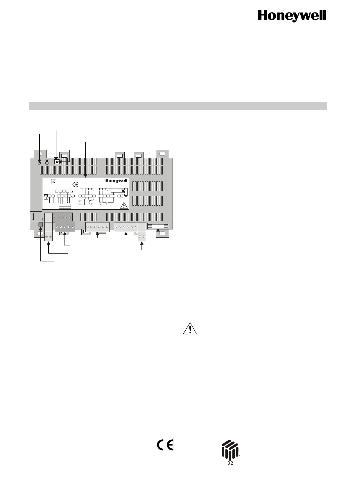
terminals for hardwiring
to wall module and/or sensor(s)
removable LonWorks
terminal plug
terminal assign-
ment label
W7754Kxxxx
230 Vac, 50/60 Hz
max. 5 VA unloaded
2 A10A
III II I
fan
relays
D-71101 Schönaich
Made in Germany
1920
2122
open
close
close
OUT1 OUT2
230 Vac
triac
0.5 A
2526
24
2A/M
LN
com
com
open
230 V
triacs
removable power
supply terminal plug
fuse
Fig. 1. Top view of Excel 10 W7754 FCU Controller
(optional terminal cover removed)
All three models of the Excel 10 W7754 Fan Coil Unit (FCU)
Controller are equipped with a minimum of
• three relays,
• one LED digital output,
• two digital inputs, and
• two analog inputs.
Further, depending on the hardware requirements of your
specific application, you can choose from among models
equipped with the following additional features:
W7754K1001
W7754P1000
W7754Q1008
See also Table 1 on page 3 for a complete overview of
terminals and their functions.
BEFORE INSTALLATION
IMPORTANT
Excel 10
W7754K,P,Q FAN COIL UNIT
CONTROLLERS
INSTALLATION INSTRUCTIONS
• 230 Vac power supply
• one triac output
• one digital output, for the low-voltage Pulse-Width
Modulated (PWM) control of a solid-state relay
employed in high-current electrical reheat applications
• three relays
• 230 Vac power supply
• four triac outputs
• four relays
• 24 Vac power supply
• four triac outputs
• four relays
It is recommended that the controller be kept at room
temperature for at least 24 hours before applying
power; this is to allow the evaporation of any
condensation resulting from low shipping / storage
temperatures.
US requirement, only: This device must be installed
in a UL-listed enclosure offering adequate space to
maintain the segregation of line voltage field wiring
and Class 2 field wiring.
CAUTION
To avoid electrical shock or equipment damage, you
must switch OFF the power supply before attaching /
removing connections to/from any terminals.
® U.S. Registered Trademark
Copyright © 2006 Honeywell Inc. EN1B-0304GE51 R0506C
All Rights Reserved
Page 2
EXCEL 10 W7754K,P,Q FAN COIL UNIT CONTROLLERS
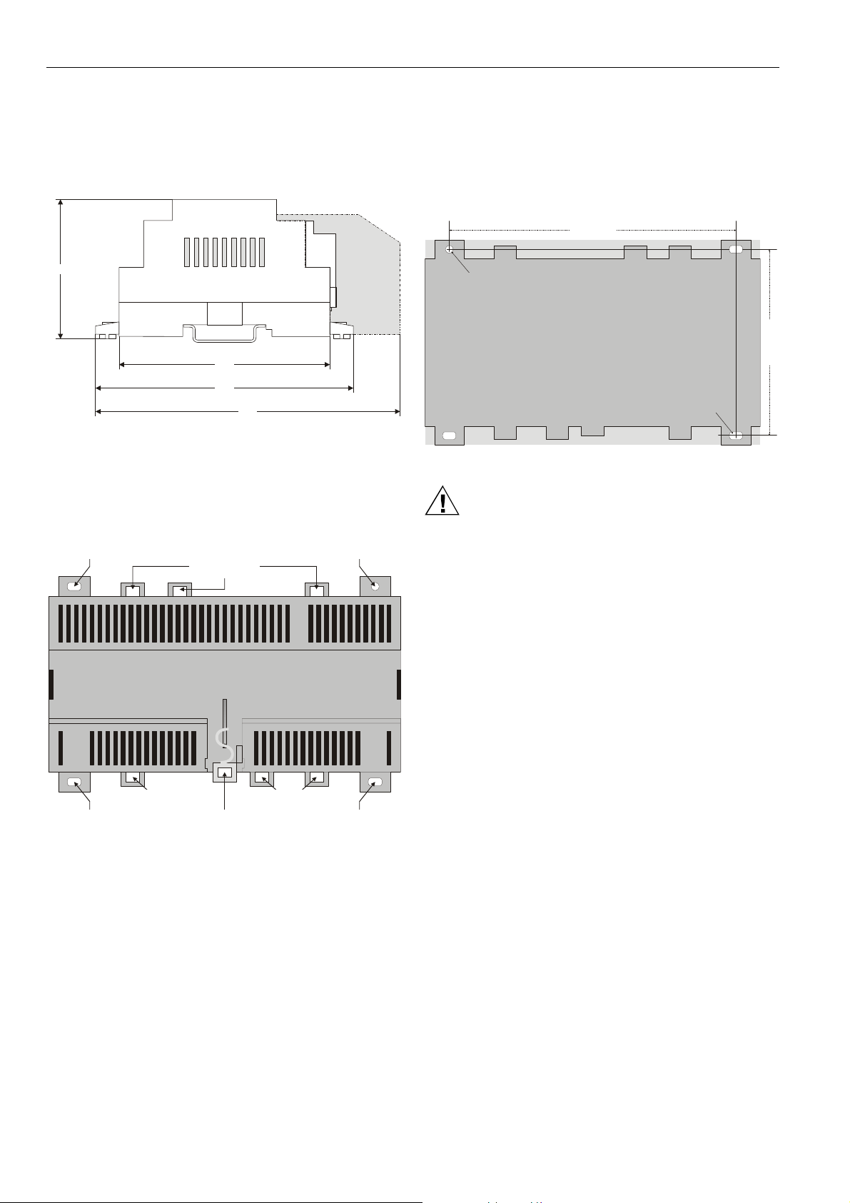
MOUNTING
All models have the same dimensions (W x L x H =
110 x 180 x 60 mm) (see Fig. 2) conforming to IP20 (without
optional terminal protection cover) or IP30 (with optional
terminal protection cover; width is then 130 mm).
59.5
cover (optional)
terminal protection
90
110
130
Fig. 2. Excel 10 W7754 dimensions (in mm)
The Excel 10 W7754 FCU Controller is suitable for mounting
on a standard rail (DIN EN 50022-35 x 7,5), on walls/ceilings,
as well as for installation in wiring cabinets or fuse boxes.
DIN Rail Mounting/Dismounting
screwing nose
(oval hole)
screwing nose
(oval hole)
eyelet for
cable binder
eyelets for
cable binders
stirrup; pull to
dismount from rail
cable binders
eyelets for
Fig. 3. Housing base (view from below)
The Excel 10 W7754 FCU Controller can be mounted onto
the DIN rail simply by snapping it into place. It is dismounted
by gently pulling the stirrup located in the base of the housing
(see Fig. 3). When mounted on a DIN rail, the unit must be
secured in place with a stopper to prevent sliding.
screwing nose
(round hole)
screwing nose
(oval hole)
Wall/Ceiling Mounting/Dismounting
The Excel 10 W7754 FCU Controller can be mounted on
walls or ceilings in any desired orientation. In the case of
ceiling mounting, however, it should not be operated at
ambient temperatures exceeding 50 °C. The unit is mounted
by inserting 3.5-mm dowel screws through the corresponding
screwing noses.
154 mm
round hole
(diameter: 4 mm)
oval hole
(4x7 mm)
Fig. 4. Drilling template (view from above)
CAUTION
In order to conform with IP30, when installed on walls
or ceilings, the Excel 10 W7754 FCU Controller must
be equipped with the optional terminal protection
cover (see section "Terminal Protection Cover" on
page 7).
After mounting the Excel 10 W7754 FCU Controller onto the
wall or ceiling, provide for cable access by snipping out the
terminal protection cover's cut-out tabs and snap it (by hand)
into place on the housing. To remove the cover, place a
screwdriver in the leverage slot and pry it loose.
Terminal Assignment
The Excel 10 W7754 FCU Controller features two rows of
terminal blocks located on one side for the connection of
cables to the relays, inputs, and outputs as well as for
connecting the removable power supply terminal plug and
removable L
NOTE: All high-voltage terminal blocks are orange-colored.
Depending on the given hardware model, the controllers have
different power supplies and are equipped with different
numbers of triac outputs, relay outputs, etc. See Table 1 on
page 3.
Every Excel 10 W7754 FCU Controller is therefore equipped
with a terminal assignment label on the top of the housing
(see Fig. 1 on page 1). This label is an adhesive sticker
displaying the maximum complement of I/O's. Terminals not
present in a given model are indicated by dotted lines.
NOTE: According to VDE guidelines, it is not allowed to mix
See also Table 3 on page 6.
ONWORKS terminal plug.
low-voltage and high-voltage signals on the relays.
100 mm
EN1B-0304GE51 R0506C
2
Page 3

EXCEL 10 W7754K,P,Q FAN COIL UNIT CONTROLLERS
Table 1. W7754 Controller: Overview of terminals and functions (by model)
ter-
minal #
function
K P Q
1+2 receiving/sending data on the LONWORKS network; removable plug X X X
a digital input, configurable (using the LNS plug-in) to read input e.g. from a
3
hardwired window contact, occupancy sensor, etc.; suitable for dry contacts, only;
X X X
max. voltage at open contact = 5 Vdc
an analog input, permanently configured to read input from a hardwired wall
4
module's temperature setpoint adjustment knob; can be enabled/disabled using
the left DIP switch
(3)
X X X
an analog input, permanently configured to read input from a hardwired wall
5
module's room temperature sensor (use NTC20k sensor, only; accuracy [w/o
sensor] = 0.5 °C at 25 °C); can be enabled/disabled using the left DIP switch
(3)
X X X
6 GND serving terminals 4, 5, 9, 10, and 11 X X X
7 not used -- -- -8 GND serving terminal 3 X X X
a digital output, permanently configured to write output switching the LED of a
9
hardwired wall module ON/OFF; can be enabled/disabled using the left DIP
(3)
switch
; max. voltage = 5 Vdc; max. current = 5 mA
X X X
an analog input, permanently configured to read input on whether a hardwired wall
10
11
module's 3-speed fan control knob has been set to AUTO, OFF, LOW, MEDIUM,
or HIGH and whether its "occupancy override" button has been pressed; can be
enabled/disabled using the left DIP switch
a digital input, permanently configured to read input on whether a window contact
is "open" or "closed"; can be enabled/disabled using the right DIP switch
(3)
(3)
;
X X X
X X X
suitable for dry contacts, only; max. voltage at open contact = 5 Vdc
12 not used -- -- --
relay 4, permanently configured to write output to a hardwired electrical reheat coil,
13+14
switching it ON/OFF; switching voltage = 24...230 Vac; switching current =
-- X --
0.05...10 A
15 a common terminal for terminals 16, 17, and 18 X X X
(1)
16
(1)
17
(1)
18
(2)
19
(2)
20
(2)
21
(2)
22
(2)
23
(2)
24
25+26
(1)
If all three relays (terminals 15 [common], 16, 17, and 18) are switched OFF, the three-speed fan will likewise be switched
relay 3, permanently configured to write output to a hardwired three-speed fan,
setting it to HIGH
relay 2, permanently configured to write output to a hardwired three-speed fan,
setting it to MEDIUM
relay 1, permanently configured to write output to a hardwired three-speed fan,
setting it to LOW
X X X
X X X
X X X
a triac output, permanently configured to write output to OUT1, closing it -- X X
a triac output, permanently configured to write output to OUT1, opening it -- X X
a triac output, permanently configured to write output to OUT2, closing it -- X X
a triac output, permanently configured to write output to OUT2, opening it X X X
a common terminal for terminals 19 and 20 X X X
a common terminal for terminals 21 and 22 X X X
the "N" (25) and "L" (26) terminals of power supply; 24 Vac (±20%), 50/60 Hz or
230 Vac (-15%/+10%), 50/60 Hz, depending upon model; removable plug
230 Vac 230 Vac 24 Vac
OFF. Switching voltage = 24...230 Vac; switching current = 0.05...3 A (max. 3 A for all three relays together).
(2)
Switching voltage = 230 Vac (230-V models) or 24 Vac (24-V models), max. switching current = 0.5 A; max. peak (10 sec)
current = 1 A
(3)
Please use an appropriate tool (e.g. ball-point pen) to operate the DIP switch.
Additionally, the W7754K1001 features an extra socket (2-pin connector located to the left of the terminal blocks; see Fig. 1 on
page 1) containing a digital output suitable for attachment to a solid-state relay (use only Carlo Gavazzi RS1A23D25-P64; max.
voltage = 12 Vdc; max. current = 12 mA at 10 Vdc) employed for low-voltage PWM control in high-current electrical reheat
applications.
Using Honeywell's LNS plug-in, you can configure the controller's triac outputs and relay outputs for a variety of different
functions. E.g. the triac outputs can be configured for connection to either a floating drive or to a thermal actuator. Once the
outputs have been configured, the corresponding devices can be directly connected to them.
model
3
EN1B-0304GE51 R0506C
Page 4

EXCEL 10 W7754K,P,Q FAN COIL UNIT CONTROLLERS
(
)
Power Supply
General Information
NOTE: All wiring must comply with applicable electrical
codes and ordinances. Refer to job or manufacturers’ drawings for details. Local wiring guidelines (e.g. IEC 364-6-61 or VDE 0100) may take
precedence over recommendations provided in
these installation instructions.
NOTE: To comply with CE requirements, devices having a
voltage of 50...1000 Vac or 75...1500 Vdc but
lacking a supply cord, plug, or other means for
disconnecting from the power supply must have the
means of disconnection incorporated in the fixed
wiring. This means of disconnection must have a
contact separation of at least 3 mm at all poles.
Use a minimum of 18 AWG (1.0 mm
14 AWG (2.5 mm
2
) for all power wiring.
Power is supplied via a removable terminal plug (attached to
terminals 25 and 26) permitting individual Excel 10 W7754
FCU Controllers to be disconnected from the power supply
without disturbing the operation of other devices powered by
the same source. See Fig. 5.
Excel 10
W7754K,P
230
230
Vac
Vac
26
230
230
Vac
Vac
252526
230
230
Vac
Vac
25 26
NL
230 Vac (15% / +10%)
50 / 60 Hz
Fig. 5. Connection to power supply
NOTE: Do not reverse the polarity of the power connection
cables, and avoid ground loops (i.e. avoid connecting one field device to several controllers) as this
may result in short circuits damaging your device.
Models with 230 Vac Power Supply (W7754K,P)
Models with 230 Vac power supply are equipped with a builtin 24 Vac transformer.
• Power supply: 230 Vac [-15% / +10%], 50/60 Hz).
• Power consumption: < 6 VA (device unloaded)
Model with 24 Vac Power Supply (W7754Q)
• Power supply: 24 Vac [±20%], 50 or 60 Hz, connected.
• Power consumption: < 3 VA (device unloaded)
2
) and a maximum of
Excel 10
W7754Q
24
24
Vac
Vac
26
24
24
Vac
Vac
252526
24 Vac
+/-20%
NL
230 Vac (15% / +10%)
50 / 60 Hz
Wall Modules
The T7460 and T7560 Wall Modules can be used in conjunction with Excel 10 W7754 FCU Controllers to perform
room temperature sensing, set-point adjustment, fan speed
manual override, and occupancy override. When hardwired to
the controller (via terminals 4, 5, 6, 9, and 10), the wall
module's LED/LCD can be configured to provide information
about
• any override of the controller by e.g. manual operation of
the wall module or the receipt by the controller of a
network command (see section "Configuration of the LED
to Display Info on Overrides" below);
• the controller's effective occupancy mode (see sections
"Configuration of the LED to Display Info on Occupancy
Mode" and "Configuration of the LCD to Display Info on
Occupancy Mode" below).
NOTE: The left DIP switch located on the top of the con-
troller (see Fig. 1 on page 1) is used to indicate that
a wall module can be hardwired to the controller.
Setting the left DIP switch to USED means that a
wall module can be hardwired; setting it to UNUSED
means that no wall module can be hardwired.
NOTE: The intended use of the wall module's buttons must
be configured using Honeywell's LNS plug-in.
Table 2. Supported wall module functions
T7560
button
override
T7460C •
T7460D •
T7460E • •
T7460F •
left •
T7560A
middle •
right •
left •
T7560B
middle •
right •
Example:
The T7560A has a left button which can be configured to act
as a fan speed button, a middle button which can be configured to act as a unit ON/OFF button, and a right button for
override. See T7460 Wall Modules Installation Instructions
(form number 95-7610) and T7560 Digital Wall Module
Installation Instructions (form number 95-7620) for details.
Configuration of the Wall Module's LED / LCD
When either a T7460 or a T7560 Wall Module has been
hardwired to the Excel 10 W7754 FCU Controller, the
module's LED can be configured (using Honeywell's LNS
plug-in) to provide information about e.g. overrides or
effective occupancy modes. Further, in the case of a T7560
Wall Module, its LCD can likewise be configured to display
such information.
Configuration of the LED to Display Info on Overrides
The wall module's LED can be configured to indicate if an
override has been activated by either the wall module's override button being pushed or because the controller has received a network command. Specifically:
unit
ON/OFF
fan speed
EN1B-0304GE51 R0506C
4
Page 5

EXCEL 10 W7754K,P,Q FAN COIL UNIT CONTROLLERS
• If the wall module's LED is OFF, then no override (from
the wall module or the L
ONWORKS network) is currently in
effect.
• If the wall module's LED is ON continuously, the override
button or a network command has placed the controller
into the "occupied" or "override" mode (however, if the
override button is again pushed or if a cancellation network command is received or if the override time expires,
the controller will return to its scheduled occupancy
mode).
• If the wall module's LED flashes once per second, the
override button or a network command has placed the
controller into the "unoccupied" mode (however, if the
override button is again pushed or if a cancellation network command is received, the controller will return to its
scheduled occupancy mode).
• If the wall module's LED flashes twice per second, a
network command has placed the controller into either
the "standby" or the "occupied" mode.
• If the wall module's LED flashes four times per second,
the controller is responding to a network management
"wink" command.
Configuration of the LED to Display Info on Occupancy Mode
The wall module's LED can also be configured to indicate the
Excel 10 W7754 FCU Controller's effective occupancy mode.
Specifically:
• If the wall module's LED is OFF, the controller is in the
"unoccupied" mode.
• If the wall module's LED is ON, the controller is in the
"occupied" mode.
• If the wall module's LED flashes once per second, the
controller is in the "standby" mode.
• If the wall module's LED flashes four times per second,
the controller is responding to a network management
"wink" command.
Configuration of the LCD to Display Info on Occupancy Mode
The T7560 Wall Module's LCD can be configured to display
various symbols to indicate the Excel 10 W7754 FCU
Controller's effective occupancy mode. Specifically:
• If
is displayed continuously, the controller is in the
"occupied" or "override" mode; if it flashes, the given
mode has been overridden.
• If
is displayed continuously, the controller is in the
"standby" mode; if it flashes, the "standby" mode has
been overridden.
• If
is displayed continuously, the controller is in the
"unoccupied" mode; if it flashes, the "unoccupied" mode
has been overridden.
NOTE: If all three of these symbols are flashing simul-
taneously, the controller is responding to a network
management "wink" command.
•
•
means that the controller is OFF.
and mean that the controller is OFF, but that "frost
protection" has been enabled.
LonWorks Communications
General Information
The Excel 10 W7754 FCU Controller is equipped with a freetopology transceiver for communication on L
networks. The L
ONWORKS network is insensitive to polarity,
eliminating the possibility of installation errors due to
miswiring.
ONWORKS®
Different network configurations (daisy-chain, loop, and star
configurations, or any combination thereof) are possible (see
also Excel 50/500 L
ONWORKS Mechanisms Interface
Description, EN0B-0270GE51).
Connecting to the LONWORKS Network
IMPORTANT
Do not bundle wires carrying field device signals or
L
ONWORKS communications together with high-
voltage power supply or relay cables. Specifically,
maintain a min. separation of 3 inches (76 mm)
between such cables. Local wiring codes may take
precedence over this recommendation.
IMPORTANT
Try to avoid installing in areas of high electromagnetic noise (EMI).
The unit must be wired to the L
ONWORKS network using level
IV 22 AWG (Belden part number 9D220150) or plenum-rated
level IV 22 AWG (Belden part number 9H2201504) nonshielded, twisted-pair, solid-conductor wire. When possible,
use Honeywell AK3781, AK3782, AK3791, or AK3792 cable
(US part numbers). See Excel 50/5000 L
ONWORKS
Mechanisms, EN0B-0270GE51, for details, including
maximum lengths.
Use wire with a minimum size of 20 AWG (0.5 mm
maximum size of 14 AWG (2.5 mm
2
).
2
) and a
D-71101 Schönaich
W7754K,P, or Q
1 2 1 2
Made in Germany
W7754K,P, or Q
D-71101 Schönaich
Made in Germany
termination
module
Fig. 6. Connection to LonWorks network and termination
module (here: daisy-chain network configuration)
The Excel 10 W7754 FCU Controller is connected to the
L
ONWORKS network via a removable terminal plug (attached
to terminals 1 and 2) permitting individual Excel 10 W7754
controllers to be connected / disconnected from the
L
ONWORKS network without disturbing the operation of other
devices.
Depending upon the chosen network configuration, one or two
terminations (see section "L
ONWORKS Termination" on page
7) may be required.
Inputs/Outputs
Wiring the Inputs/Outputs
Use a minimum size of 20 AWG (0.5 mm2) and a maximum of
14 AWG (2.5 mm
maximum length of all input/output cables is 400 m.
Two wires with a total thickness of 14 AWG can be twisted
together and connected using a wire nut (include a pigtail with
this wire group and attach the pigtail to the individual terminal
block). Deviations from this rule can result in improper
electrical contact. Local wiring codes may take precedence
over this recommendation.
2
) for all input/output connections. The
5
EN1B-0304GE51 R0506C
Page 6

EXCEL 10 W7754K,P,Q FAN COIL UNIT CONTROLLERS
Digital Inputs
The Excel 10 W7754 FCU Controller's digital inputs are
suitable for connection with dry contacts, only.
Digital Outputs
The triac outputs or relay outputs can be configured (using
Honeywell's LNS plug-in) for different functions.
You can configure the four triac outputs for connection to
either a floating drive or to a thermal actuator. Once the outputs have been configured, the corresponding devices can be
directly connected to them.
Table 3. Output assignments for various actuator types
output type stage
floating -- close open close open
1-stage
2-stage
3-stage
PWM -- -- PWM -- PWM
thermal -- -- ON/OFF -- ON/OFF
0 -- OFF -- OFF
1 -- ON -- ON
0 OFF OFF OFF OFF
1 OFF ON OFF ON
2 ON OFF ON OFF
0 OFF OFF OFF OFF
1 OFF ON OFF ON
2 ON OFF ON OFF
3 ON ON ON ON
OUT1 OUT2
19 20 21 22
Relay Outputs
The W7754K1001 is equipped with three relays; the
W7754P1000 and W7754Q1008 have four relays.
Hardware Limits
• A min. current of 50 mA is required to ensure a reliable
contact.
• The normally-open contacts are designed for a max.
continuous current of 3 A (for relays 1, 2, and 3 together)
and 10 A (relay 4), respectively.
NOTE: If inductive components are to be connected to the
relays and if these relays switch more often than
once every two minutes, these components must be
prevented from causing harmful interference to radio
or television reception (conformance with
EN 45014).
Triac Outputs
The Excel 10 W7754 FCU Controller is equipped (depending
upon the model) with one to four triac outputs.
Hardware Limits for Excel 10 W7754K,P (230 Vac Power Supply)
• Low signal: 0 V; high signal: 230 Vac
• Maximum allowable continuous current for each
individual triac output: 500 mA
• Maximum allowable peak current (for 10 seconds) for
each individual triac output: 1 A
• Maximum allowable continuous current for all of the
triac outputs together: 1 A.
• cos ϕ > 0.8
Hardware Limits for Excel 10 W7754Q1008 (24 Vac Power Supply)
• Low signal: 0 V; high signal: 24 Vac
• Maximum allowable continuous current for each
individual triac output: 500 mA
• Maximum allowable peak current (for 10 seconds) for
each individual triac output: 1 A
• Maximum allowable continuous current for all of the
triac outputs together: 1 A.
• cos ϕ > 0.8
Analog Inputs
The Excel 10 W7754 FCU Controller is equipped with two
analog inputs (for connection to a room sensor and to a wall
module with temperature setpoint adjustment, respectively).
Table 4. Analog input usage
analog input wall module
AI1 room sensor
AI2 setpoint adjustment
1) If the sensor measures a temperature outside of the range
of 0...70 °C, this is interpreted as a sensor break / short
circuit.
1)
Replacing the Fuse
NOTE: Before replacing the fuse (see also Fig. 1 on page
1), disconnect the controller from the power source
by detaching the removable terminal plug attached
to terminals 25 and 26.
CAUTION
Depending upon actual wiring, even after you have
switched OFF the power supply, the relays may still be
under high voltage.
When replacing the controller's fuse, please replace with the
same type listed on the terminal assignment label (e.g.:
F2.5H250V).
Troubleshooting
All Excel 10 W7754 FCU Controllers feature a LONWORKS
service LED and corresponding L
(see Fig. 1) for commissioning and troubleshooting.
When the service button is pressed, the service pin message
is broadcast.
See Table 5 on page 7 for a description of the meaning of the
various different possible behaviors of the L
LED. For more information on standard service LED behavior,
refer to Motorola L
Manual, page AL-190.
ONWORKS Technology Device Data
Possible Problems and Recommended Actions
Check if the LONWORKS service LED's behavior is changed if
you switch the power OFF/ON. Please contact Honeywell if
this does not solve the problem.
ONWORKS service button
ONWORKS service
EN1B-0304GE51 R0506C
6
Page 7

EXCEL 10 W7754K,P,Q FAN COIL UNIT CONTROLLERS
Accessories
Terminal Protection Cover
Required for wall/ceiling mounting. Set of eight covers.
• order no.: XAL_COV_L
LONWORKS Termination
One or two LONWORKS terminations are required, depending
on the given LonWorks bus layout. See section "Connecting
to the L
ONWORKS Network" on page 5.
Two different L
• L
ONWORKS termination module, order no.: 209541B
• L
ONWORKS connection / termination module (mountable
on DIN rails and in fuse boxes), order no.: XAL-Term
removable screw-type
3-pole terminal block
Fig. 7. L
ONWORKS termination modules are available:
l
l
e
w
y
e
n
o
H
m
r
e
T
-
L
A
X
4
3
L
L
O
O
N
N
ONWORKS connection and termination module
plug-in
jumper
3
4
LON
Termi nat ion
FTT/LPT Bus
FTT/LPT Free
Park Position
5
1
shield shield
06
Table 5. LONWORKS Service LED Behaviors and Meanings
1
2
3
4
5
6a
6b
6c
6d
7
8
LED blinking pattern meaning
Defective device hard-
LED remains OFF after power-up.
LED is lit continuously after first
power-up.
LED flashes at power-up, goes OFF,
then is lit continuously.
LED flashes briefly periodically.
LED repeatedly blinks ON for 1 s
and OFF for 1 s.
OFF duration ≈ 10 s. Afterwards, the
service LED turns ON and remains
ON, indicating completion of the
blanking process.
OFF duration ≈ 1 s. Afterwards, the
service LED is lit continuously.
OFF duration is 1...15 s, depending
on application size and system
clock. Afterwards, service LED repeatedly blinks ON for 1 s and OFF
for 1 s.
OFF duration is indefinite (1...15 s to
load internal EEPROM; remains
OFF).
LED remains OFF after a short ON
duration.
LED flashes ON. Controller has received
ware. Suspect power
supply problems, clock
problems, or defective
Neuron Chip.
Defective hardware.
Controller lacks
application.
Controller is probably ex-
periencing continuous
watchdog resets, or external memory or
EEPROM is corrupt.
Controller is unconfigured
but has an application.
Using EEBLANK on a
Neuron 3150 Chip-based
custom node.
First power-up with a new
PROM on a Neuron 3150
Chip-based customized
node. Application-less
firmware state exported.
Controller is configured
and running normally.
WINK command from
network. Other physical
outputs are unaffected.
7
EN1B-0304GE51 R0506C
Page 8

EXCEL 10 W7754K,P,Q FAN COIL UNIT CONTROLLERS
Manufactured for and on behalf of the Environmental and Combustion Controls Division of Honeywell Technologies Sàrl, Ecublens, Route du Bois 37, Switzerland by its Authorized Representative:
Automation and Control Solutions
Honeywell GmbH
Böblinger Straβe 17
D-71101 Schönaich
Phone: (49) 7031 63701
Fax: (49) 7031 637493
http://europe.hbc.honeywell.com
Subject to change without notice. Printed in Germany Manufacturing location certified to
EN1B-0304GE51 R0506C
 Loading...