

Page 1
BEFORE INSTALLATION
The Excel 10 Fan Coil Unit (FCU) Controller is available in
the following five models:
1. W7752D2007
—230 Vac power with electric reheat relay.
2. W7752E2004
—230 Vac power without electric reheat relay.
3. W7752F2002
—115 Vac power with electric reheat relay.
4. W7752G2000
—115 Vac power without electric reheat relay.
5. W7752J2003
—100 Vac power without electric reheat relay.
Excel 10
W7752D,E,F,G,J FAN COIL UNIT
CONTROLLERS
INSTALLATION INSTRUCTIONS
panel with screws or by snapping onto standard EN 50 022
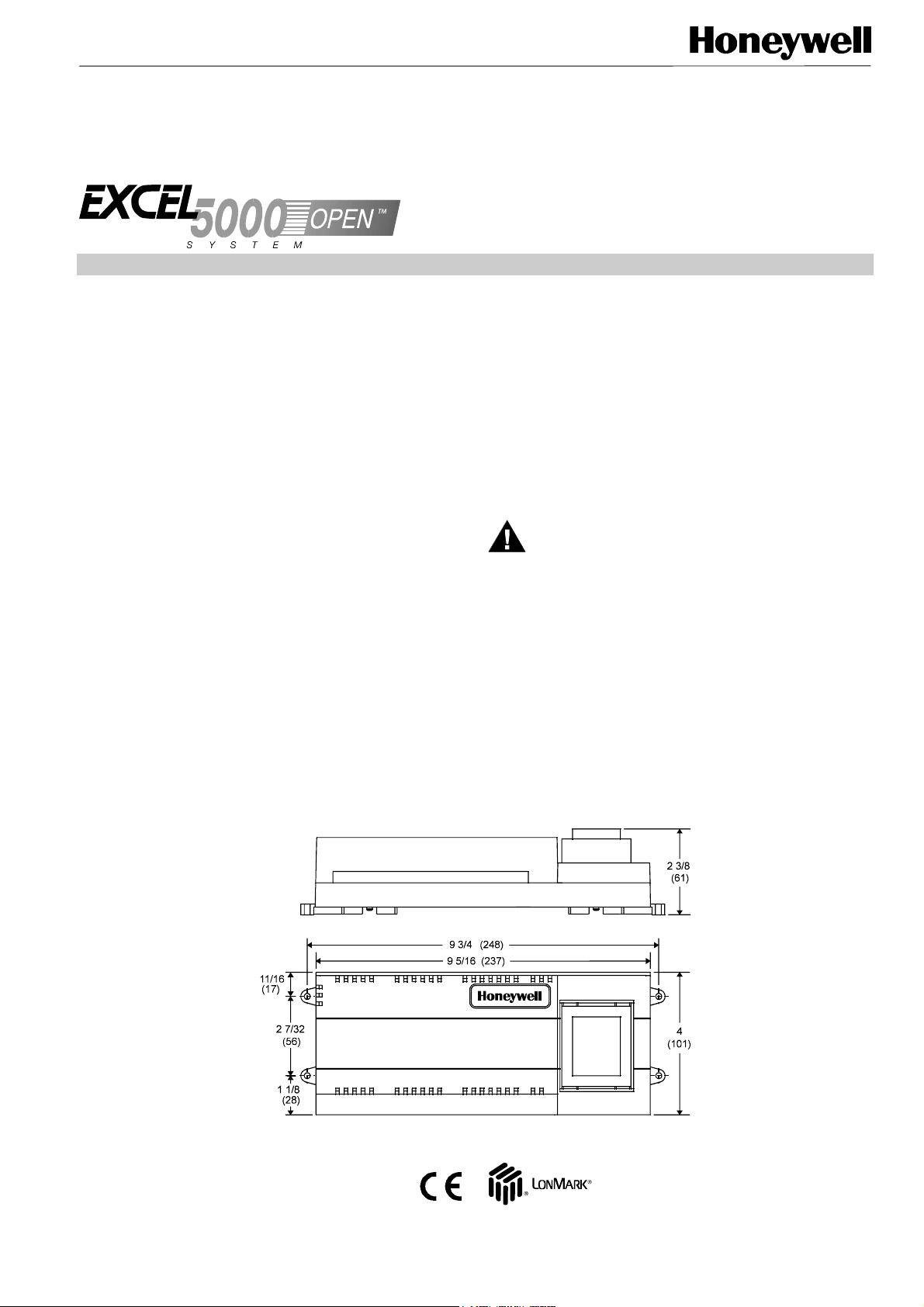
DIN rail, 1-3/8 by 9/32 in. (35 mm by 7.5 mm). See Fig. 1 for
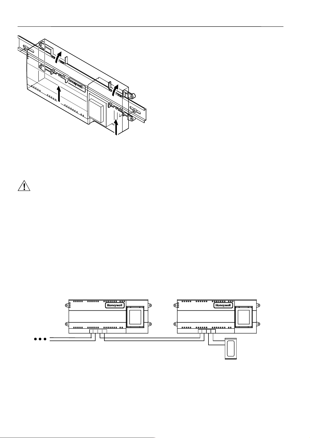
mounting dimensions. See Fig. 2 for DIN rail mounting. The
type and length of screw required for screw mounting
depends upon the panel material used to mount the controller.
The controller can be mounted either vertically or horizontally. However, if thermal actuators are connected to the
controller outputs, it is recommended that the controller be
mounted so that the transformer is not located beneath the
electronics.
The models all have identical housings and mounting
procedures.
IMPORTANT
It is recommended that devices be kept at room
temperature for at least 24 hours before applying
power to allow any condensation resulting from low
shipping/storage temperatures to evaporate.
This device must be installed in a UL-listed
enclosure offering adequate space to maintain the
segregation of line voltage field wiring and Class 2
field wiring (US requirement only).
INSTALLATION
Mount the Fan Coil Unit controllers in locations that allow
clearance for wiring. The controllers can be mounted on a
WARNING
ELECTRICAL SHOCK HAZARD.
Source power at terminal block can cause personal
injury or death. W7752 FCU Controllers must be
mounted inside their respective fan coil unit boxes to
prevent access by unauthorized personnel.
To reduce the risk of fire or electric shock, install in a
controlled environment relatively free of
contaminants.
Wiring
All wiring must comply with applicable electrical codes and
ordinances. Refer to job or manufacturers’ drawings for
details.
Fig. 1. Excel 10 Fan Coil Unit Controller outside and mounting dimensions in in. (mm).
® U.S. Registered Trademark
Copyright © 2003 Honeywell Inc. EN1B-0250GE51 R0703
All Rights Reserved 7157 234
Page 2
W7752D,E,F,G,J FAN COIL UNIT CONTROLLERS
N
Fig. 2. DIN rail mounting.
Power
Input power provided must be 230 Vac (+10%, -15%), 50 or
60 Hz for W7752D and E; 115 Vac (+10%, -15%), 50 or
60 Hz for W7752F and G, and 100 Vac (±6%), 50 or 60 Hz
for W7752J.
CAUTION
Turn off power prior to connecting to or removing
connections from any terminals to avoid electrical
shock or equipment damage.
Use the heaviest gauge wire available, up to 14 AWG (2.5
2)
with a minimum of 18 AWG (1.0 mm2) for all power
mm
wiring. Strain relief/support must be provided for power wiring
within 2-3/8 in. (60 mm) of controller connection.
IMPORTANT
To comply with CE requirements, with devices
having a voltage range of 50 to 1000 Vac or 75 and
1500 Vdc which are not provided with a supply cord
and a plug or with other means for disconnection
from the supply having a contact separation of at
least 3 mm in all poles, the means for disconnection
must be incorporated in the fixed wiring.
Communications
Wire the controller communications E-Bus using level IV 22
AWG (Belden part number 9D220150) or plenum-rated level
IV 22 AWG (Belden part number 9H2201504) nonshielded,
twisted pair, solid conductor wire. When possible, use
Honeywell AK3781, AK3782, AK3791, or AK3792 cable (US
part numbers).
Pull the cable to each controller on the E-Bus and connect to
terminals 9 and 10.
The W7752 FCU Controller utilizes a free topology
transceiver (FTT10A) E-Bus which allows daisy-chain, loop,
and star network configurations or any combination thereof.
Depending upon the E-Bus configuration used, one or two
termination modules, part number 209541B, may be
required. Different connections to the termination module are
necessary depending upon whether it is used in a singly- or
doubly-terminated network configuration. See Excel 10
FTT/LPT 209541B Termination Module Installation
Instructions, form 95-7554.
NOTES:
— The E-Bus is insensitive to polarity, eliminating
installation errors due to miswiring.
— Do not bundle output wires with sensor, digital input or
communications bus wires. Maintain a minimum 3 in.
(76 mm) separation between E-Bus and Triac output
wiring.
— For installations, try to avoid areas of high electro-
magnetic noise (EMI).
— Some T7770 Wall Modules used for 2000-series FCU
controllers have a daisy-chain connection for the E-Bus
to provide network access via built-in jack.
— For more information see E-Bus Wiring Guidelines, form
number 74-2865.
Wall Modules
A variety of Excel 10 wall modules can be used with W7752
FCU Controllers. See T7460 Wall Modules Installation
Instructions (form number 95-7610) and T7560 Digital Wall
Module Installation Instructions (form number 95-7620) for
installation details.
W7752 FAN COIL UNIT CONTROLLER
12
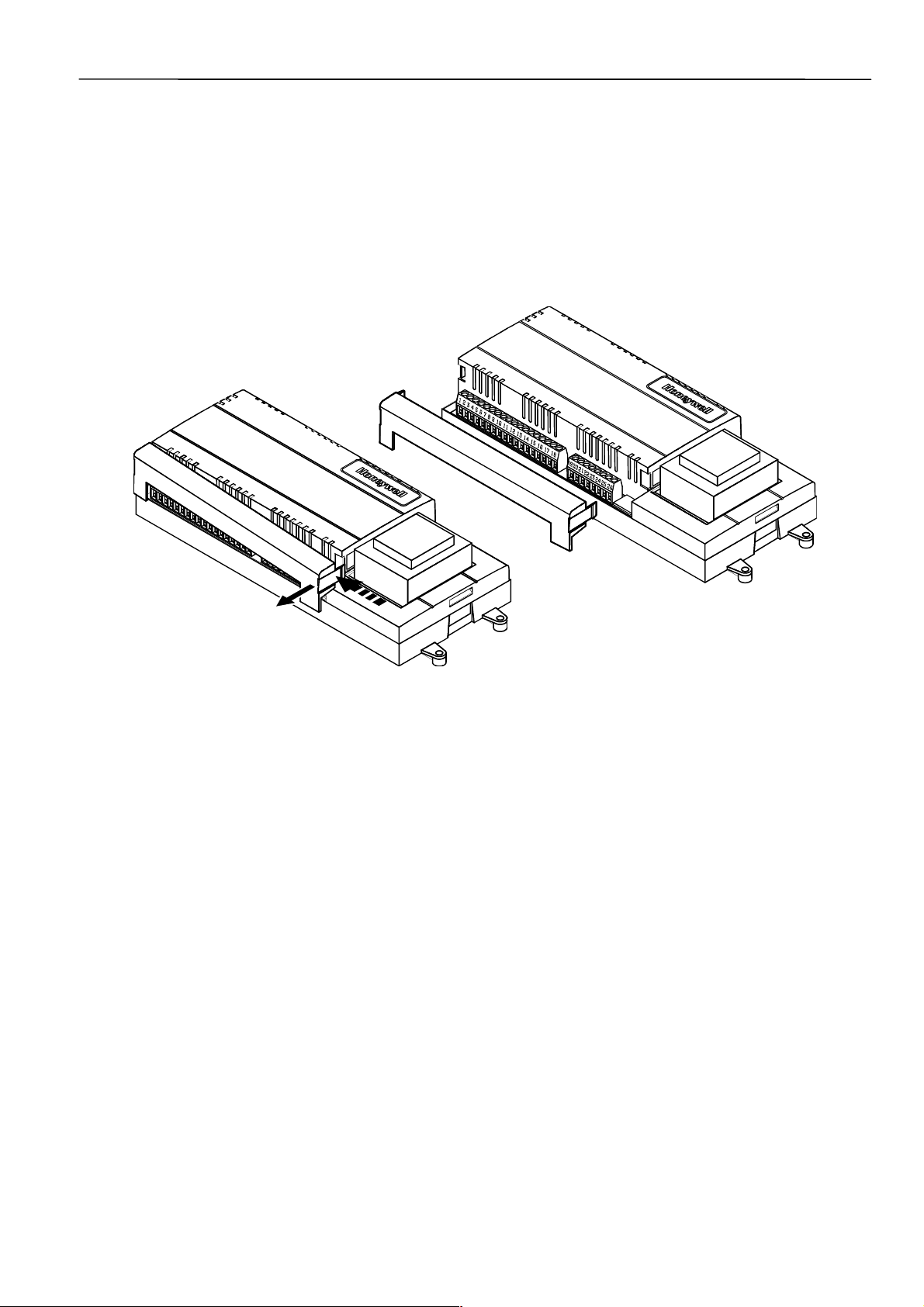
Fig. 3. Termination module connection (daisy-chain network configuration).
EN1B-0250GE51 R0703 2
W7752 FAN COIL UNIT CONTROLLER
991010111112
TERMINATIO
MODULE
Page 3
W7752D,E,F,G,J FAN COIL UNIT CONTROLLERS
Wiring Details
Connections to the FCU controllers are made at two terminal
blocks protected by a plastic cover. W7752D and F models
have two additional terminals on terminal block 2 for electric
reheat connections. Fig. 4 shows removal of the terminal
block cover.
2
Use a minimum wire size of 20 AWG (0.5 mm
input/output connections. Use a minimum of 16 AWG
(1.5 mm
2
) for electric reheat output connections. The
maximum length of all input/output cables and wall module
) for all
interface cables is 65 ft (20 m). The maximum length for fan
power switching cables is 3 1/2 ft (1 m).
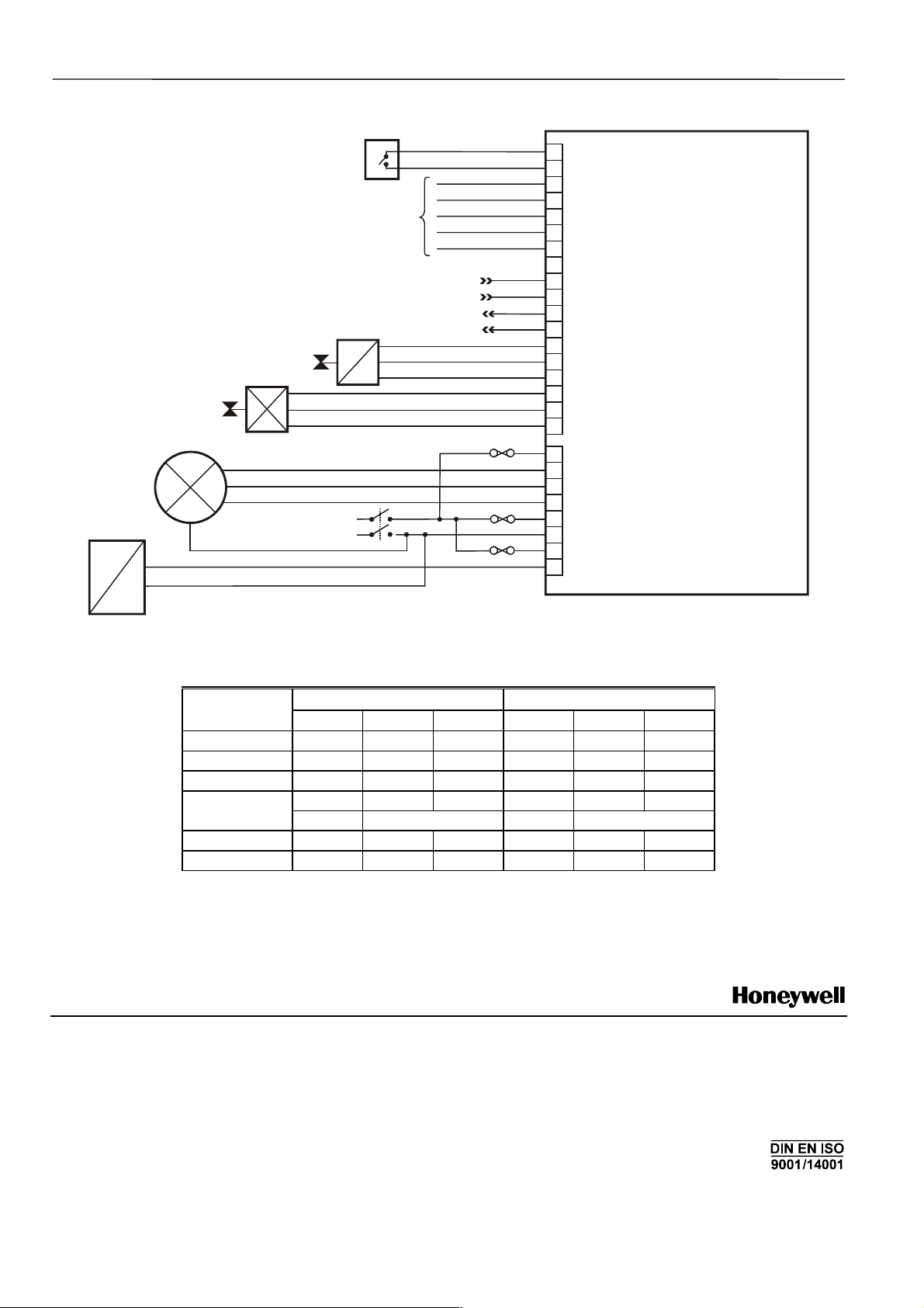
Fig. 6 illustrates the terminal assignments of the controllers.
Table 1 lists Triac output assignments for various actuator
types. Refer to job drawings for specific wiring diagrams.
IMPORTANT
Screw type terminal blocks are designed to accept
no more than one 14 AWG (2.5 mm
Multiple wires that are 14 AWG (2.5 mm
2
) conductor.
2
) can be
connected using a wire nut. Include a pigtail with
this wire group and attach the pigtail to the
individual terminal block.
Fig. 4. Terminal cover removal.
Wire to the terminal blocks as follows:
1. Strip 1/2 in. (13 mm) insulation from the conductor.
2. Insert the wire in the required terminal location and
tighten the screw to complete the termination.
3. If two or more wires are being inserted into one
terminal location, twist the wires together before
inserting them.
IMPORTANT
When two or more wires are to be attached to the
same terminal, be sure to twist them together.
Deviations from this rule can result in improper
electrical contact. See Fig. 5. Local wiring codes
may take precedence over this recommendation.
3 EN1B-0250GE51 R0703
Page 4
W7752D,E,F,G,J FAN COIL UNIT CONTROLLERS
OCCUPANCY SENSOR
CHANGEOVER CONTACT
AIRFLOW CONTACT
WINDOW CONTACT
MOTION SENSOR
WALL MODULE
CONNECTIONS
LONW
ORKS
L
ONWORKS
COM
+
OPEN
CLOSE
L
N
REHEAT
+
COOL
FAN
RETURN
-
LO
MED
HI
POWER MAINS
HEAT
COM
OPEN
CLOSE
NETWORK IN
NETWORK OUT
4A
0.5A
16A
W7752 FAN COIL UNIT CONTROLLER
D
G
N
D
1
T
A
D
G
I
I
L
N
I
P
U
2
3
LED
SETPOINT
4
FAN / BYPASS
5
TEMP SENSOR
6
AGND
7
8
9
E-BUS IN
E-BUS IN
10
E-BUS OUT
11
12
E-BUS OUT
OUT 1 COM
13
OUT 1 OPEN
14
15
OUT 1 CLOSE
16
OUT 2 COM
17
OUT 2 OPEN
OUT 2 CLOSE
18
19
RELAY COM
20
RELAY 1
21
RELAY 2
22
RELAY 3
23
SUPPLY VOLT
24
SUPPLY VOLT
PWR RELAY IN (D,F MODELS ONLY)
25
26
PWR RELAY OUT (D,F MODELS ONLY)
T
Output type Out 1 Terminal Out 2 Terminal
Floating 24 Vac open close 24 Vac open close
1-stage 24 Vac on/off — 24 Vac on/off —
2-stage 24 Vac stage 1 stage 2 24 Vac stage 1 stage 2
3-stage 24 Vac stage 1 stage 2 24 Vac stage 1 stage 2
PWM 24 Vac PWM — 24 Vac PWM —
Thermal 24 Vac on/off — 24 Vac on/off —
Automation and Control Solutions
Honeywell AG
Böblinger Straβe 17
D-71101 Schönaich / Germany
Phone: (49) 7031 637 - 01
Fax: (49) 7031 637 - 493
http://europe.hbc.honeywell.com
Fig. 6. FCU Controller terminal assignments.
Table 1. Output assignments for various actuator types.
13 14 15 16 17 18
stage 3 stage 3
Subject to change without notice. Printed in Germany Manufacturing location certified to
MU1B-0250GE51 R0703
7157 234
 Loading...