

Page 1
Excel 10
W7751H3007 VAV ACTUATORS
HONEYWELL EXCEL 5000 OPEN SYSTEM
BEFORE INSTALLATION
The W7751H Smart VAV Actuator consists of a factorycombined variable air volume (VAV) box controller and a
direct-coupled damper actuator with de-clutch mechanism.
The actuator/controller assembly is field-mounted to the VAV
box damper shaft similar to the mounting of a standard
actuator, and the controller wiring is terminated to the screw
terminals accessible inside the detachable wiring box. See
Fig. 2.
The W7751H's built-in actuator with de-clutch mechanism
allows the installer to manually open or close its built-in VAV
box damper without power or software tool.
The W7751H contains a Free Topology Transceiver (FTT)
LonMark® compliant controller containing a Microbridge flowthrough pressure sensor and communicates via the 78 kbaud
L
ONWORKS
The W7751H actuator mounts directly onto the VAV box
damper shaft and has up to 6 Nm torque, 95 degree stroke,
and 110 sec. timing at 50 Hz and 90 sec at 60 Hz.
If desired, the SSW2 Auxiliary Switch Kit (see "SSW2
Auxiliary Switch Kit for N05xx, N10xx Non-Spring Return
Direct-Coupled Damper Actuators – Installation Instructions",
Product Literature No.: MU1B-0284GE51) can be attached to
the W7751H. See also section "Optional Accessories" on
page 9.
NOTE: Any hardware driven by the triac outputs must have
® Network.
a min. current draw, when energized, of 25 mA at
24 Vac and a max. current draw of 770 mA.
INSTALLATION INSTRUCTIONS
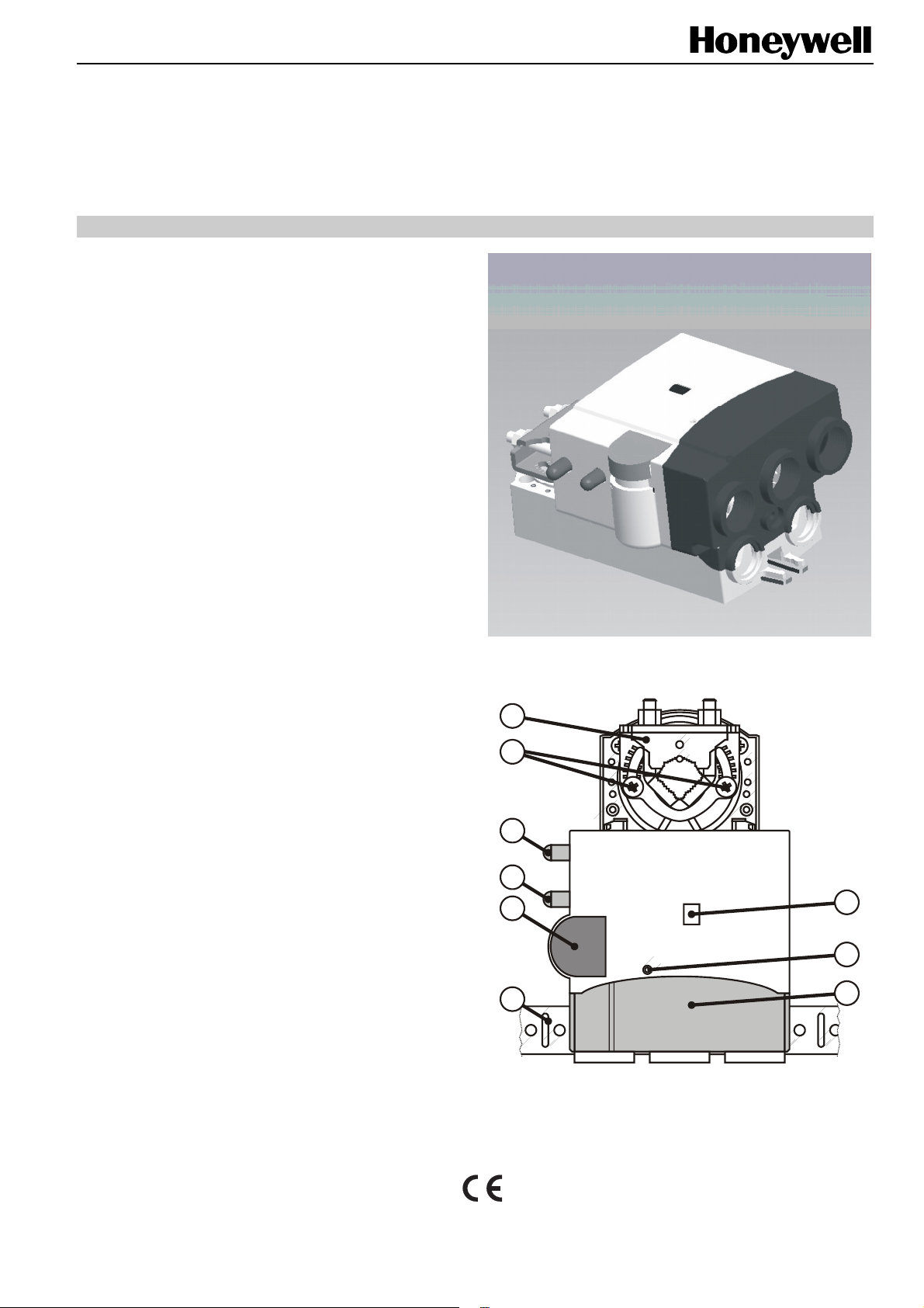
Fig. 1. Excel 10 Smart VAV Actuator
1
2
MAIN FEATURES
Legend for Fig. 2:
1) Universal shaft adapter
2) Mechanical end limits (manually adjustable in increments
of 5.5°)
3) Air flow pick-up connector (-LO)
4) Air flow pick-up connector (-HI)
5) L
ONWORKS
6) Declutch button
7) L
ONWORKS
8) Detachable wiring box
9) Anti-rotation bracket
® U.S. Registered Trademark EN1B-0279GE51 R0707B
Copyright © 2007 Honeywell Inc. • All rights reserved
service LED
service pin
3
4
6
5
7
9
Fig. 2. W7751H main features
8
Page 2
EXCEL 10 W7751H SMART VAV ACTUATOR
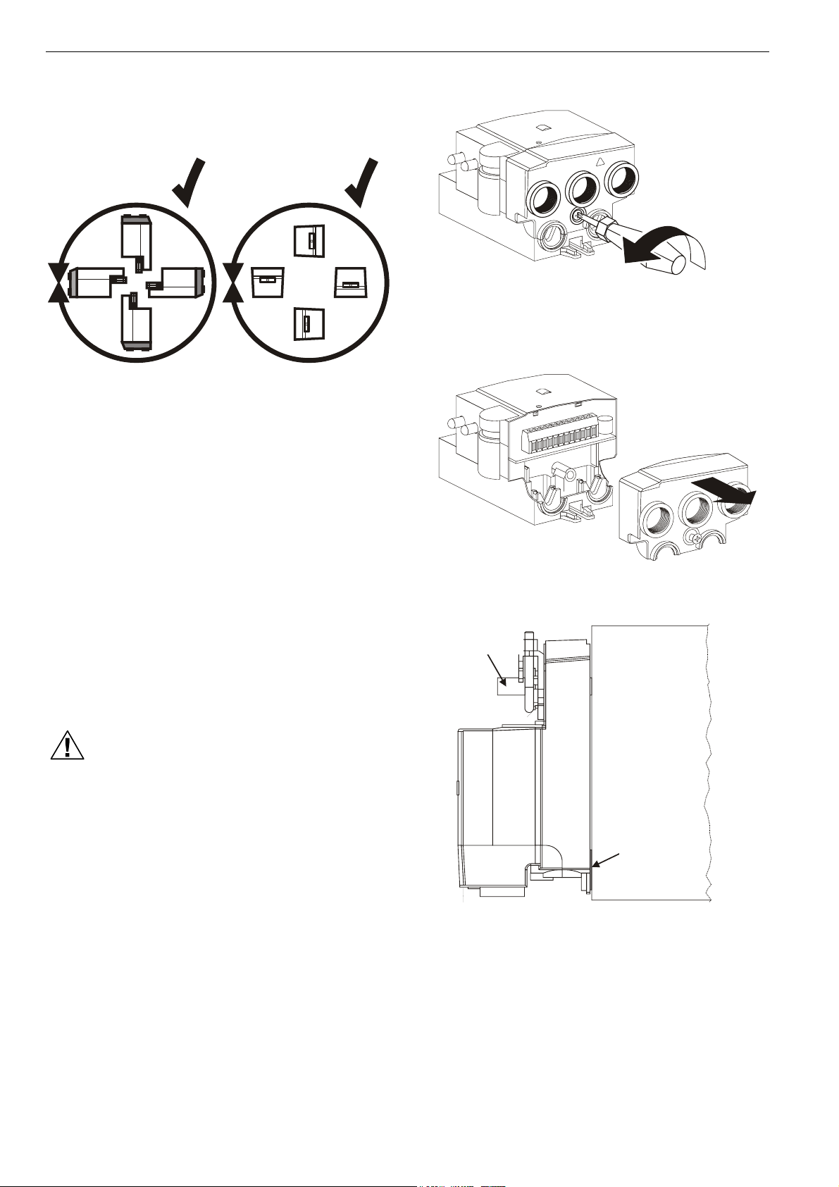
INSTALLATION
The W7751H provides IP40 in all mounting orientations.
IP40 IP40
360° 360°
2
1
1
1
0
1
9
8
7
6
5
4
3
2
1
Fig. 4. Opening wiring box (1)
Fig. 3. Permissible orientations providing IP40
Mount the W7751H on the damper shaft and allow clearance
for wiring, servicing, and module removal. Avoid mounting the
W7751H in areas where acid fumes or other corrosive vapors
can attack the actuator's metal parts, or in areas where
escaping gas or other explosive vapors are present. See Fig.
23 for mounting dimensions.
The W7751H is field-mounted to the VAV box damper shaft.
The W7751H actuator opens or closes a damper by driving
the damper shaft in either the counterclockwise (CCW) or
clockwise (CW) direction. If the W7751H is to be mounted
directly onto a damper shaft, use the mounting bracket and
screw included in the delivery.
The wiring of the W7751H controller is terminated to a screw
terminal block accessible inside the detachable wiring box.
See section "Wiring".
The W7751H actuator is shipped in the fully counterclockwise
(CCW) position (95 degrees). Mount the W7751H so that the
actuator is parallel with the VAV box damper housing.
CAUTION
Equipment damage hazard.
Mounting actuator unevenly with damper housing
can damage actuator.
Mount the actuator flush with the damper housing or
add a spacer between the anti-rotation bracket and
the VAV damper box housing (see Fig. 6).
4
3
2
1
2
1
1
1
0
1
9
8
7
6
5
Fig. 5. Opening wiring box (2)
VAV b ox
damper shaft
VAV b ox
damper housing
spacer or washer
Fig. 6. Mounting W7751H with washer/spacer
Before mounting the W7751H onto the VAV box damper
shaft, do the following:
1. Ensure that the diameter of the damper shaft is within the
allowed limits (round: 8…16 mm, square: 6…13 mm).
EN1B-0279GE51 R0707B
2
Page 3
2. Ensure that the damper shaft has a length of at least
40 mm.
3. Determine the direction (CW or CCW) in which the
damper shaft rotates to open the damper (see Fig. 7).
4. Determine the angle of the damper opening (can be
adjusted in increments of 5.5°).
TYPE A DAMPER
COOLING
AIR FLOW
CW TO OPEN, CCW TO CLOSE
TYPE B DAMPER
COOLING
AIR FLOW
CCW TO OPEN, CW TO CLOSE
Fig. 7. Determining direction of rotation
The W7751H actuator is shipped in the fully counterclockwise
(CCW) position (95 degrees). The installation procedure
varies depending on the damper direction.
NOTE: Be aware that, until the W7751H is powered and the
damper is driven open, starting the fan system with
all the VAV box dampers closed can cause duct
over-pressurization and damage.
If Damper Rotates CW to Open
If the damper rotates clockwise (CW) to open, mount the
W7751H as follows:
1. Manually open the damper.
2. Push down the declutch button of the W7751H, and while
holding it down, manually rotate its shaft adapter fully to
the clockwise position.
3. Mount the W7751H to the VAV damper box and shaft.
4. Set the mechanical end limits of the W7751H (see Fig. 8).
When the W7751H closes, the damper will thus rotate
CCW until the mechanical end limits are reached.
If Damper Rotates CCW to Open
If the damper rotates counterclockwise (CCW) to open, mount
the W7751H as follows:
1. Manually open the damper.
2. Push the declutch button of the W7751H, and while
holding it down, manually rotate its shaft adapter fully to
the counterclockwise position.
3. Mount the W7751H to the VAV damper box and shaft.
4. Set the mechanical end limits of the W7751H (see Fig. 8).
When the W7751H closes, the damper will thus rotate CW
until the mechanical end limits are reached.
EXCEL 10 W7751H SMART VAV ACTUATOR
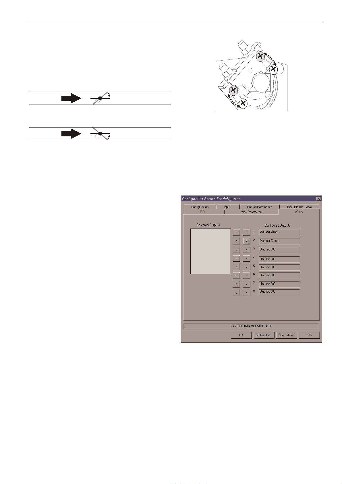
Fig. 8. Setting the mechanical end limits
Reconfiguring to Match Rotation Direction
Using the LNS plug-in, the W7751H can be reconfigured to
match the direction the damper shaft rotates to open the
damper. Reconfigure the damper's direction of rotation to
"open" or "closed," according to your needs.
To change the damper direction from CW to CCW using the
LNS plug-in, proceed as follows.
1. Open the configuration part of the plug-in and select the
"Wiring" tab (see Fig. 9).
Fig. 9. Wiring tab (default configuration)
2. Then deselect the output configuration (see Fig. 10).
3
EN1B-0279GE51 R0707B
Page 4

EXCEL 10 W7751H SMART VAV ACTUATOR
fan startup. Use the de-clutch button to open the
W7751H's box damper only after the W7751H has
been powered down (this is to prevent overpressurization in the ductwork on fan startup). To
use the de-clutch button, press and hold down the
button (this disengages the motor). Turn the damper
shaft until the damper is open and then release the
button. When power is restored to the W7751H, it
synchronizes the damper actuator so that the
damper is in the correct position on startup.
Air Flow Pick-up
Connect the air flow pick-up to the two connectors on the
W7751H. See Fig. 12.
AIRFLOW DELTA-P PICK-UP
AIRFLOW
DIRECTION
Fig. 10. Deselecting the output configuration
3. Now, configure the outputs so that the W7751H operates
counterclockwise (CCW) (see Fig. 11).
Fig. 11. Configuring the W7751H to open CCW
The damper direction has now been reconfigured.
IMPORTANT
It is recommended that the dampers be left in an
"open" position after W7751H installation to avoid
the possibility of over-pressurizing the ductwork on
-LOW
+HIGH
Fig. 12. Air flow pick-up connections
NOTES:
• Use 6-mm outside diameter with 1-mm wall thickness
plenum-rated 1219 FR (94V-2) pneumatic tubing.
• Always use a fresh cut on the end of the tubing that
connects to the air flow pick-ups and the connectors on
the W7751H.
Connect the high pressure or upstream tube to the plastic
restrictor labeled (+ HI) or P1 and the low-pressure or downstream tube to the restrictor labeled (- LO) or P2. See labeling
in Fig. 12.
NOTE: If controllers are mounted in unusually dusty or dirty
environments, a 5-micron disposable air filter is recommended for the high-pressure line (marked as +)
connected to the air flow pick-up.
When twin tubing is used from the pick-up, split the pick-up
tubing a short length to accommodate the connections.
NOTES:
• The tubing from the air flow pick-up to the W7751H should
not exceed 0.914 m in length. Lengths much longer than
this can degrade the flow sensing accuracy.
EN1B-0279GE51 R0707B
4
Page 5
• To avoid damaging the air flow connectors, use caution
when removing tubing from them. Always pull straight
away from the connector; never remove by pulling at an
angle.
Wiring
All wiring must comply with applicable electrical codes and
ordinances, or as specified on installation wiring diagrams.
NOTES:
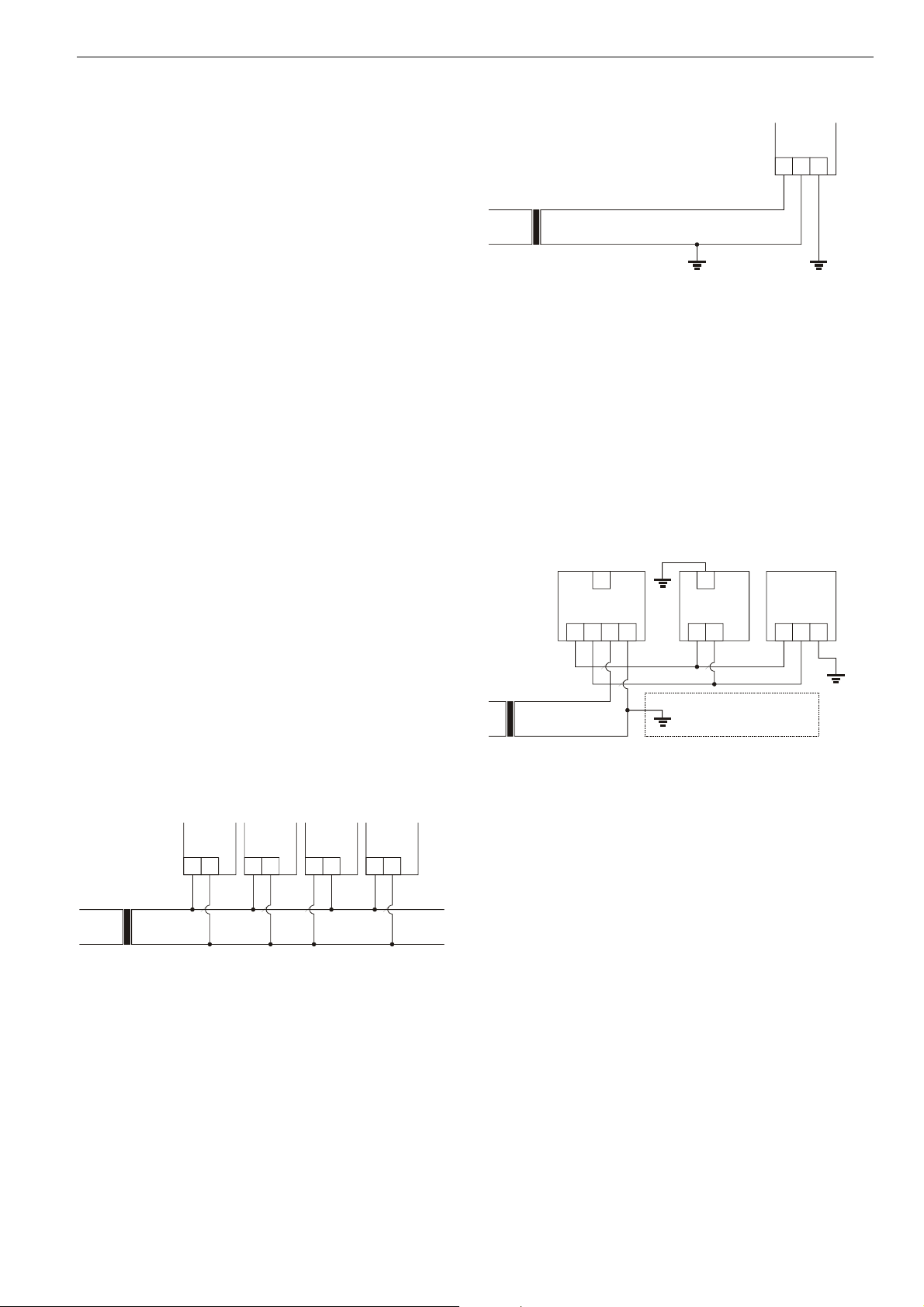
• 24 Vac power connections. Verify that multiple controllers
powered by the same transformer are wired with the
transformer secondary connected to the same input
terminal numbers on each W7751. See Fig. 13. Controller
configurations are not necessarily limited to three devices,
but the total power draw including accessories cannot
exceed 100 VA when powered by the same transformer.
For power wiring recommendations, refer to Excel 10
W7751B,D,F,H,J Variable Air Volume Controller –
Application Guide (Product Literature No.: 74-2949).
• In the case of multiple W7751H units operating from a
single transformer, the same side of the transformer
secondary must be connected to the same input terminal
in each W7751H and the ground terminals (terminal 3 of
the W7751H) must be connected to a verified earth
ground for each controller in the group. See Fig. 14.
Controller configurations are not necessarily limited to
three devices, but the total power draw including
accessories cannot exceed 100 VA when powered by the
same transformer. For power wiring recommendations,
refer to Excel 10 W7751B,D,F,H,J Variable Air Volume
Controller – Application Guide (Product Literature No.: 74-
2949).
• All loads on a W7751H must be powered by the same
transformer that powers the W7751H.
• Keep the earth ground connection (terminal 3) wire run as
short as possible. See Fig. 14.
• Do not connect the analog ground (terminal 5) to the earth
ground. See Fig. 15.
W7751H W7751H W7751H W7751H
21 21 21 21
24 VAC
50/60 Hz
COM
Fig. 13. Wiring multiple W7751 units (with transformer
secondary connected to same input terminal numbers)
X
EXCEL 10 W7751H SMART VAV ACTUATOR
W7751H
231
24 VAC
50/60 Hz
COM
Fig. 14. Earth grounding
Power
The 24 Vac power from an energy-limited Class II Power
Source must be provided to each W7751H. To conform to
Class II restrictions, transformers must not be larger than 100
VA.
IMPORTANT
Power must be OFF prior to connecting to or
disconnecting from output terminals 9 and 10.
Use the heaviest gauge wire available, up to 2.0
mm2 with a minimum of 1.0 mm
2
, for all power and
earth ground wiring. For non-plenum, open areas,
run cables exposed (or in conduit, if required).
2832
W7751D,F
24V 24VCOM COM
234
24 VAC
50/60 Hz
W7751B
W7751H
9110
IF THE W7751H IS USED IN UL 1995
EQUIPMENT AND THE PRIMARY
POWER IS MORE THAN 150 V,
GROUND ONE SIDE OF TRANSFORMER SECONDARY.
231
Fig. 15. Power wiring for multiple controllers
NOTES:
• Unswitched 24 Vac power wiring can be run in the same
conduit as the L
ONWORKS
® network cable.
• Maintain a 76-mm separation between triac outputs and
L
ONWORKS
® network wiring throughout the installation.
Communications
See Chapter "LonWorks System Engineering" of Excel
50/500 LonWorks Mechanisms – Interface Description
(Product Literature No.: EN0B-0270GE51) for a complete
description of L
cable types for L
is Level IV 0.34 mm
twisted pair, solid conductor wire. For non-plenum areas, US
part AK3781 (one pair) or US part AK3782 (two pair) can be
uses. In plenum areas, US part AK3791 (one pair) or US part
AK3792 (two pair) can be used. Communications wiring can
be run in a conduit, if needed, with non-switched 24 Vac or
sensor wiring. Only one router is allowed with each Excel 10
ONWORKS
ONWORKS
® network topology rules. Approved
® network communications wiring
2
plenum or non-plenum rated unshielded,
5
EN1B-0279GE51 R0707B
Page 6

EXCEL 10 W7751H SMART VAV ACTUATOR
V
Zone Manager, and each network segment can have a
maximum of one repeater.
Pull the cable to each device on the L
ONWORKS
® network and
connect to communication terminals 11 and 12 of the
W7751H.
Notes on Communications Wiring:
• All field wiring must conform to local codes and
ordinances (or as specified on the installation drawings).
• Approved cable types for LONW
munications wiring is Level IV 0.34 mm
ORKS
® network com-
2
plenum or nonplenum rated unshielded, twisted pair, solid conductor
wire. For non-plenum areas, US part AK3781 (one pair) or
US part AK3782 (two pair) can be used. In plenum areas,
US part AK3791 (one pair) or US part AK3792 (two pair)
can be used.
• Unswitched 24 Vac power wiring can be run in the same
conduit as the L
ONWORKS
® network cable.
• Do not bundle output wires with sensor, digital input or
LONW
ORKS
® network wires.
• Ensure that neither L
ONWORKS
® bus wire is grounded.
• In noisy (high EMI) environments, avoid wire runs parallel
to noisy power cables, motor control centers, or lines containing lighting dimmer switches, and keep at least 76 mm
of separation between noisy lines and the L
ONWORKS
®
network cable.
• Do not use different wire types or gauges on the same
L
ONWORKS
® bus segment: Step changes in line impedance characteristics cause unpredictable reflections
on the L
• For L
ONWORKS
ONWORKS
® bus.
termination, use an XAL-Term or a
209541B termination module.
Verify Termination Module Placement
The installation wiring diagrams should indicate the locations
for placement of termination module(s). See Chapter
"LonWorks System Engineering" of Excel 50/500 LonWorks
Mechanisms – Interface Description (Product Literature No.:
EN0B-0270GE51). Correct placement of the termination
module(s) is required for proper L
ONWORKS
® network
communications.
Wiring Details
Wire to the terminal blocks as follows:
1. Strip 5 mm insulation from the conductor
2. Insert the wire into the required terminal location and
tighten the screw to complete the termination.
NOTE: Earth ground wire length should be held to a
minimum. Use the heaviest gauge wire available, up
to 14 AWG (2.0 mm2), with a minimum of 18 AWG
(1.0 mm
NOTE: With the exception of 2.0 mm2, if inserting two or
more wires into one terminal location, use end
sleeves. Deviation from this rule can result in
improper electrical connection.
2
).
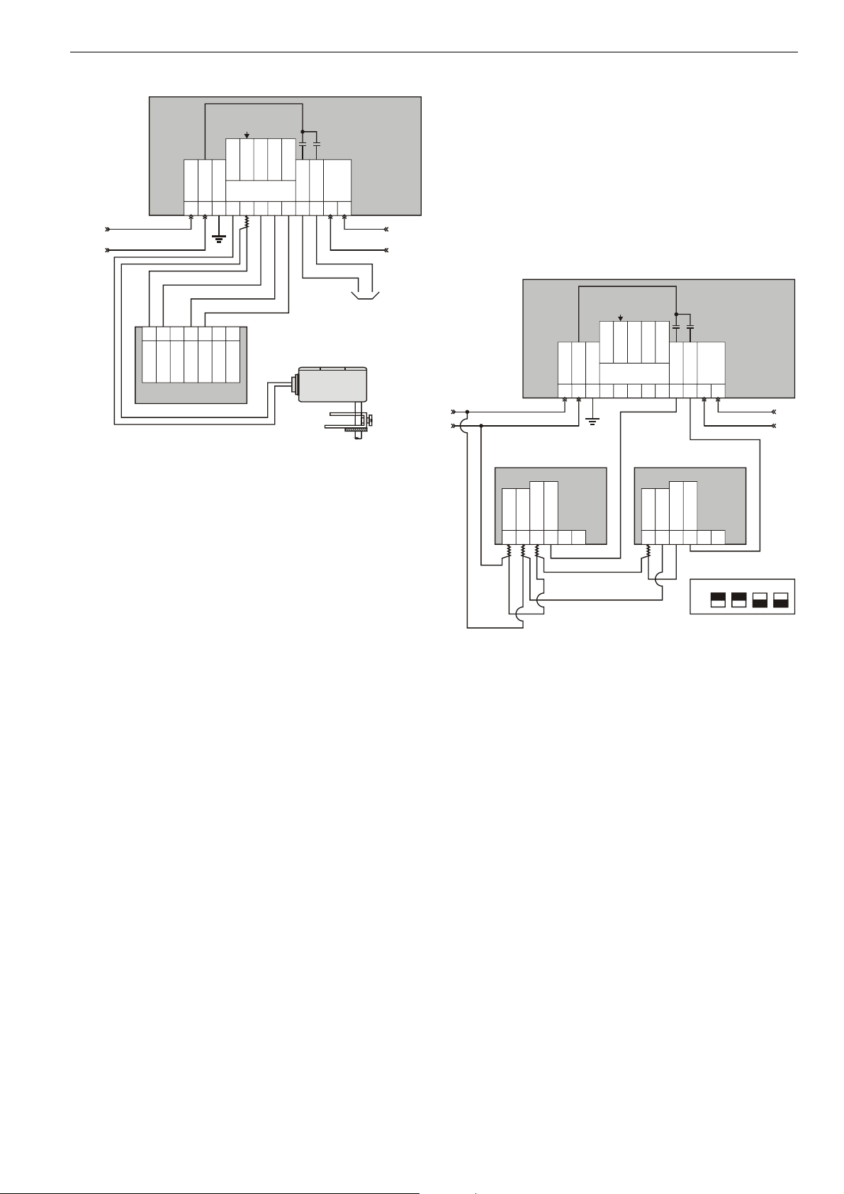
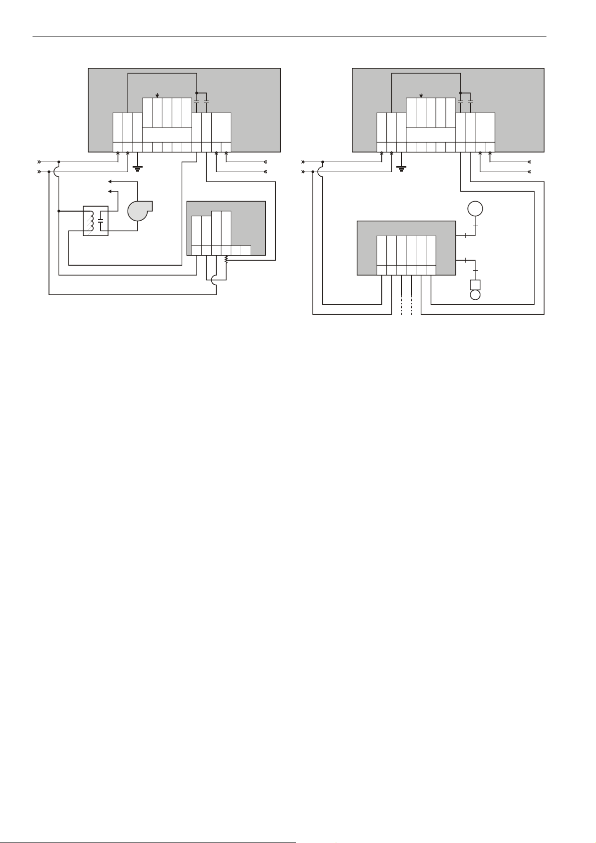
Fig. 16 through Fig. 21 provide detailed wiring diagrams for
the W7751H. See the installation diagrams for specific wiring.
NOTE: Ensure that the wall module's Configuration DIP
Switch is set as shown in Fig. 19. Switches 1 through
3 set the timing of the valve actuator to match the
W7751H outputs (minimum of 0.1 s, with a max. time
of 25.6 s). Switch 4 determines the action of the
actuator (OFF = Direct Acting, ON = Reverse
Acting).
TRIAC
NOT EARTH
GROUND
EQUIVALENT
CIRCUIT
W7751H
LED
GND
BYPASS
SENSOR
SET PT
24VAC
COM
21
MODULE
EARTH
3
4
WALL
765
8
OUT1
9 10
OUT2
1112
LON
24VAC COMM IN
5
1 234
COM
SENSOR
6 7
OPEN SIGNAL
LED
BYP/FAN
LED/RTN
BYP/RTN
SET PT
CLOSED SIGNAL
T7460E
STEM
UP
ALVE ACTUATOR
COM
STEM
DOWN
Fig. 16. W7751H modulating reheat valve wiring diagram
TRIAC
NOT EARTH
GROUND
EQUIVALENT
CIRCUIT
W7751H
LED
GND
BYPASS
SENSOR
SET PT
24VAC
COM
21
EARTH
MODULE
3
4
WALL
765
8
OUT1
9 10
OUT2
1112
LON
24VAC COMM IN
1 234
COM
SENSOR
SET PT
T7460E
STAGE 1
5
6 7
LED
BYP/FAN
LED/RTN
BYP/RTN
LINE POWER
STAGE 2
Fig. 17. W7751H two-stage reheat wiring diagram
EN1B-0279GE51 R0707B
6
Page 7
EXCEL 10 W7751H SMART VAV ACTUATOR
*
TRIAC
NOT EARTH
GROUND
EQUIVALENT
CIRCUIT
W7751H
LED
GND
BYPASS
SENSOR
SET PT
WALL
COM
24VAC
EARTH
MODULE
5
3
21
24VAC COMM IN
1 2 3 456
BYP/FAN
SET PT
LED
BYP/RTN
COM
SENSOR
76
4
8
*
7
TEMPERATURE SENSOR
LED/RTN
OUT1
OUT2
9 10
1112
MODULATING OR
STAGED REHEAT
LF20 DUCT
LON
WIRED FOR
T7460E
TO ASSURE PROPER ELECTRICAL CONTACT, WIRES
MUST BE TWISTED TOGETHER BEFORE INSERTION.
Fig. 18. W7751H discharge air sensing
CHECKOUT
Step 1. Wiring Connections
Inspect all wiring connections at the W7751H and the T7460
terminals, and verify compliance with installation diagrams. If
any wiring changes are required, first be sure to remove
power from the controller before starting work. Pay particular
attention to:
• Controller wiring: Be sure that each W7751H is wired
(terminal 3 on the W7751H) to a verified earth ground
using a wire run as short as possible with the heaviest
gauge wire available, up to 2.0 mm
1.0 mm2 for each controller in the group. See Fig. 15.
• Verify that triac wiring to external devices uses the proper
load power/24 Vac Hot terminal (terminal 1 on the
W7751H).
NOTE: All wiring must comply with applicable electrical
codes and ordinances. See the installation diagrams
for specific wiring.
Step 2. Startup
Broadcasting the Service Message
The Service Message allows a device on the LONW
network to be positively identified. The Service Message contains the device's ID number and, therefore, can be used to
confirm the physical location of a particular W7751H in a
building. There are two methods for broadcasting the Service
Message from the W7751H:
1. Operating the service pin on the W7751H: Insert a thin rod
(e.g. paper clip) into the service pin hole (see Fig. 2) and
push briefly; the Service Message will then be broadcast
on the network.
2
with a minimum of
ORKS
®
2. Using the wall module bypass button: By pressing the wall
module's bypass/override button for more than four
seconds, the W7751H will send the Service Message (this
functionality is supported in firmware version 1.2.15 and
higher). When employing this method, the occupancy
override state of the W7751H changes depending upon
how long the bypass/override button is pressed. For
example, if the button is pressed for six seconds, the
W7751H will send the Service Message and also enter
into the "continuous unoccupied" mode. To clear the
"continuous unoccupied" mode, the button must be
pressed briefly.
TRIAC
EQUIVALENT
CIRCUIT
LED
BYPASS
LON
OUT1
OUT2
765
9 10
8
1112
24VAC
COM
21
NOT EARTH
EARTH
3
4
GROUND
GND
SENSOR
SET PT
WALL
MODULE
24VAC COMM IN
PERIPHERAL HEAT
VALV E AC TUATOR
ML7984B
PWM VALVE ACTUATOR
COM
24 VAC
PWM 24VAC
FROM CNTRL
PWM OUTPUT
T6T5C B W R
TO ASSURE PROPER ELECTRICAL
CONTACT, WIRES MUST BE TWISTED
*
TOGETHER BEFORE INSERTION.
REHEAT
VALVE ACTUATOR
ML7984B
PWM VALVE ACTUATOR
COM
24 VAC
PWM 24VAC
FROM CNTRL
PWM OUTPUT
T6T5C B W R
****
CONFIGURATION DIP SWITCHES
LOCATED ADJACENT TO INPUT
TERMINAL BLOCK ON ML7948B
ON
OFF
Fig. 19. W7751H to PWM Valve Actuator
NOTE: Ensure that all transformer wiring is as shown.
Reversing terminations will result in equipment
malfunction.
W7751H
4321
7
EN1B-0279GE51 R0707B
Page 8
EXCEL 10 W7751H SMART VAV ACTUATOR
*
TRIAC
NOT EARTH
GROUND
EQUIVALENT
CIRCUIT
W7751H
LED
GND
BYPASS
SENSOR
SET PT
24VAC
COM
21
EARTH
MODULE
3
4
WALL
5
76
8
OUT1
9 10
OUT2
1112
LON
24VAC COMM IN
REHEAT
VALV E AC TUATO R
ML7984B
PWM VALVE ACTUATOR
COM
24 VAC
PWM 24VAC
FROM CNTRL
PWM OUTPUT
T6T5C B W R
CONTACTOR
(24 VAC)
SERIES OR
PAR ALLE L FAN
*
TO ASSURE PROPER ELECTRICAL
CONTACT, WIRES MUST BE TWISTED
TOGETHER BEFORE INSERTION.
Fig. 20. W7751H to PWM Valve Actuator and series or
parallel fan
Alarms
CARE is used to perform the ID Assignment task. Once ID
Assignment has been performed and commissioning has
been completed, check the L
determine if there are any alarms. Possible alarm causes can
be determined by viewing the nvoAlarm e.g. in CARE.
LONW
ORKS
Service LED
The LONW
ORKS
Service LED on the front of the W7751H (see
Fig. 2) provides a visual indication of the status of the device.
When the W7751H receives power, the LED appears in one
of the following allowable states:
1. OFF = no power to the processor.
2. Continuous ON = processor is in initialized state.
3. Slow blink = controlling, normal state.
4. Fast blink = the W7751H has an alarm condition.
When the W7751H has an alarm condition, it reports it to the
central node on the L
ONWORKS
10 Zone Manager). Also, the W7751H variables, AlarmLogX,
where X is 1 through 5, that store the last five alarms to occur
in the controller, are available. These points can be viewed
using XBS or the corresponding LNS plug-in. For a
description of Excel 10 Alarms, refer to Table 12 of Excel 10
W7751B,D,F,H,J Variable Air Volume Controller – Application
Guide (Product Literature No.: 74-2949)
NOTE: The node can be reset by switching the node to
MANUAL and then to the normal operating mode.
ONWORKS
service LED to
® network (typically, the Excel
TRIAC
NOT EARTH
GROUND
EQUIVALENT
CIRCUIT
W7751H
LED
GND
BYPASS
SENSOR
SET PT
24VAC
COM
21
EARTH
MODULE
3
4
WALL
765
8
OUT1
9 10
OUT2
1112
LON
24VAC COMM IN
OPTIONAL 24 VAC WIRING
TO NEXT CONTROLLER
*
MMC325 PNEUMATIC
TRANSDUCER
COM
COM
24 VAC
24 VAC
INCREASE
DECREASE
*
M
M
B
USE 1/4 IN. (6 MM)
MIN. TUBING.
BRANCH LINE MUST
BE 6 FT. (1.8 M)
OR LONGER.
PNEUMATIC
VALV E
Fig. 21. W7751H to pneumatic transducer
NOTE: Reverse wires (INCREASE/DECREASE) to reverse
action (DIRECT/REVERSE).
T7460 Wall Module Override LED
The remote override LED, located on either the T7460 Wall
Module, will display the "manual override" mode of the
W7751H. Possible modes are:
1. LED = OFF. No override active.
2. LED = Continuously ON. Bypass mode (timed occupied
override).
3. LED = One flash per second. Continuous unoccupied
override.
4. LED = Two flashes per second. Remote only, continuous
occupied override.
Step 3. I/O Tests
The W7751H controller must be configured using the LNS
plug-in. Once this is done, the W7751H can be commanded
to the "manual" mode, and each output and input can be
exercised/viewed to verify proper wiring connections and
equipment operation.
W7751H Actuator Checkout
To check out the W7751H actuator, determine the direction
the damper shaft moves to open the damper (CW or CCW).
See Fig. 7.
Connect the W7751H with the laptop PC. To do this, the
W7751H must be wired, powered, and connected to the
portable PC via the LonTalk adapter. The LonTalk® Adapter
connects to the W7751H either directly via the L
network or via the T7460-LONJACK (accessory available with
the T7460 and T7560 Wall Modules). Using the L
ONWORKS
ONWORKS
®
EN1B-0279GE51 R0707B
8
Page 9
EXCEL 10 W7751H SMART VAV ACTUATOR
tool, you should then drive the W7751H actuator fully open
and then closed. Observe the actuator's operation; if the
damper is closed, it should begin to open. If the damper is
open, it should begin to close.
If no movement is observed, check to see if 24 Vac is present
at the W7751H. With proper wiring, with 24 Vac present, and
with proper commands from the LNS plug-in, the actuator
should operate properly.
Step 4. Verify Sequences of Operation
For the detailed descriptions of the sequences of operation,
see Excel 10 W7751B,D,F,H,J Variable Air Volume Controller
– Application Guide (Product Literature No.: 74-2949).
Optional Accessories
Spare Parts Kit
Order no.: A7211.2071. Contains:
• 1 anti-rotation bracket + screws
• 2 universal terminal blocks
• 2 strain-relief clamps
• 2 grommets*
• 2 adjustable end stops
*In order to guarantee IP54, only original Honeywell
grommets may be used.
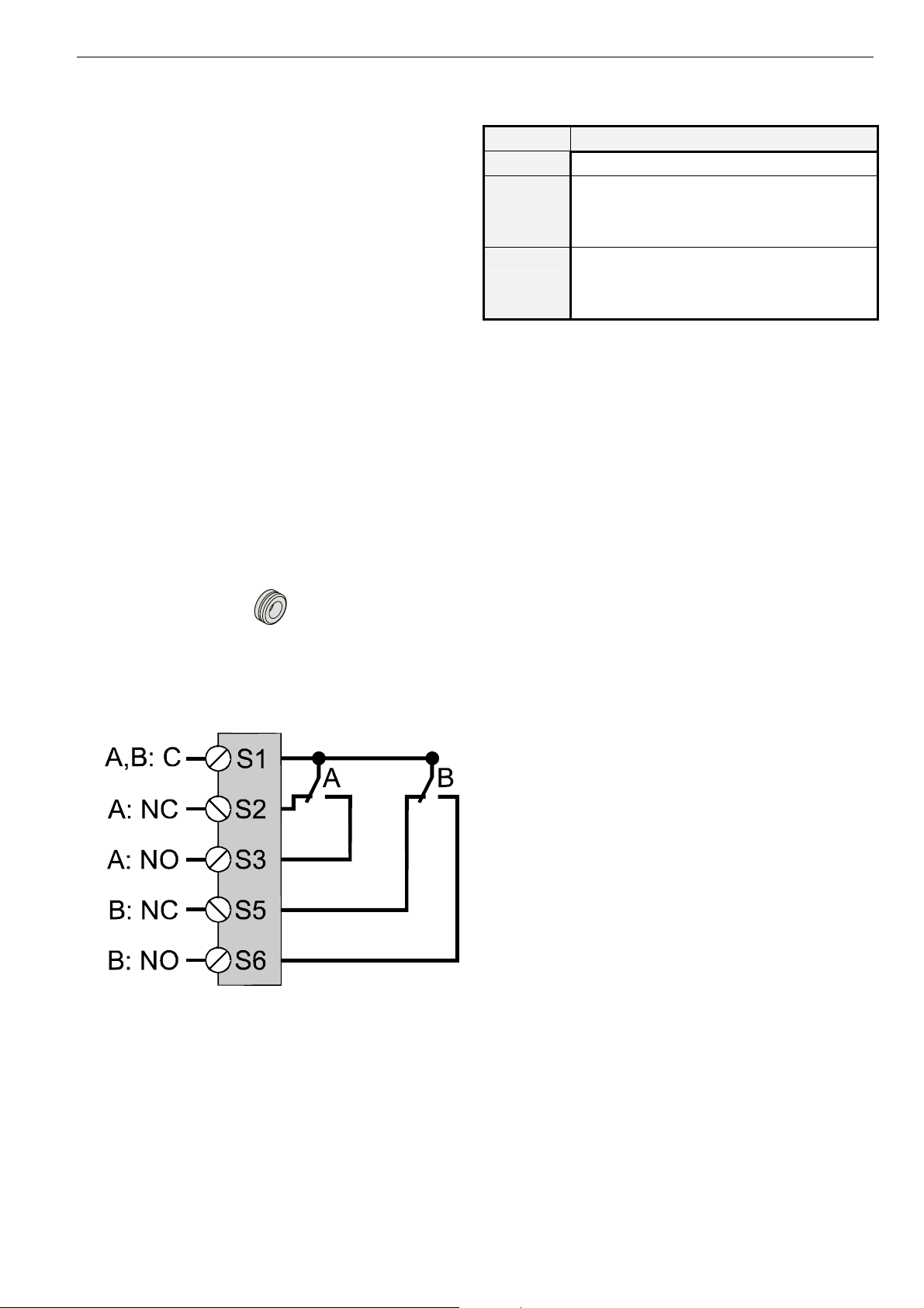
Table 1. Internal end switches of SSW2
terminal type of switch
S1
S2 / S3
S5 / S6
common lead for switches A and B
change-over switch A (S1/S2 opens and S1/S3
closes when shaft adapter moves CW past 5°;
reverts to original state when shaft adapter
moves CCW past 5°).
change-over switch B (S1/S5 opens and S1/S6
closes when shaft adapter moves CW past 85°;
reverts to original state when shaft adapter
moves CCW past 85°).
SSW2 Auxiliary Switch Kit
Fig. 22. Internal end switches of SSW2 (max. 230 V, 5 A)
NOTE: Both internal end switches must be connected to the
same power source.
9
EN1B-0279GE51 R0707B
Page 10
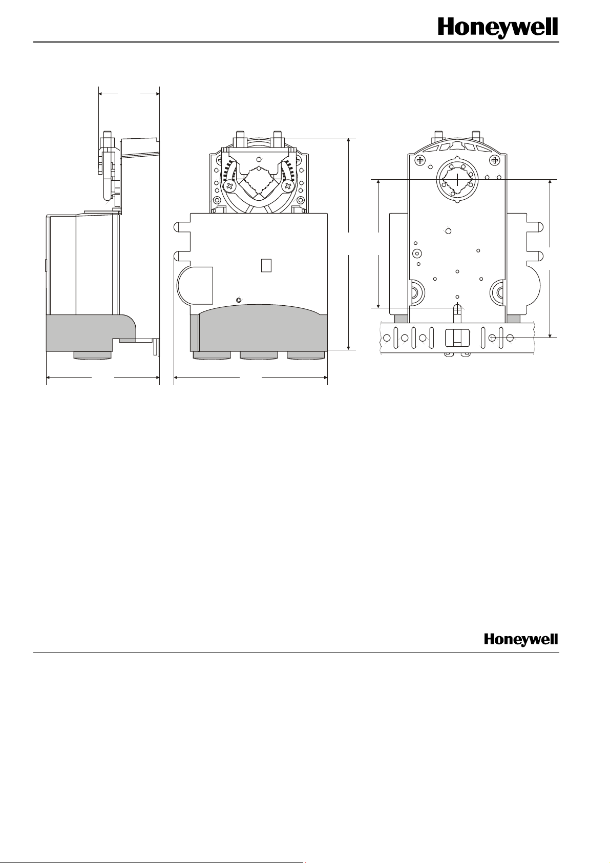
41
85
142
105
76
Manufactured for and on behalf of the Environmental and Combustion Controls Division of Honeywell Technologies Sàrl, Ecublens, Route du Bois 37, Switzerland by its Authorized Representative:
Automation and Control Solutions
Honeywell GmbH
Böblinger Straße 17
71101 Schönaich
Germany
Phone: (49) 7031 63701
Fax: (49) 7031 637493
http://europe.hbc.honeywell.com
Subject to change without notice. Printed in Germany
EN1B-0279GE51 R0707B
103
Fig. 23. Dimensions (in mm)
 Loading...