

Page 1

([FHO
:%')+
9$9,,&RQWUROOHUV
Introduction
............................................................................................................................... 4
Description of Devices........................................................................................... 4
Control Application................................................................................................. 4
Control Provided.................................................................................................... 7
Products Covered.................................................................................................. 9
Organization of Manual.......................................................................................... 9
Applicable Literature.............................................................................................. 10
Product Names...................................................................................................... 10
Agency Listings...................................................................................................... 11
Abbreviations and Definitions ................................................................................ 12
Zone Control Definitions ........................................................................................ 13
Variable Air Volume ATUs ................................................................................ 13
Air Terminal Unit Control................................................................................... 13
Pressure - Dependent And Pressure - Independent Control ............................ 13
Variable Air Volume ATUs (VAV)...................................................................... 13
Single Duct Variable Air Volume (VAV) Systems.............................................. 14
Pressure Dependent Throttling VAV Boxes...................................................... 14
Pressure Independent VAV Boxes.................................................................... 14
Series Fan Powered VAV Boxes....................................................................... 14
Parallel Fan Powered VAV boxes..................................................................... 14
Induction VAV Boxes ........................................................................................ 14
Single-Duct Constant Volume Zone Reheat Air Terminal Units........................ 15
Dual Duct Air Handling Systems....................................................................... 15
Variable Constant Volume (Zero Energy Band) Dual-Duct VAV Boxes............ 15
Dual Duct Constant Volume Systems............................................................... 15
Dual-duct mixing box terminal units.............................................................. 15
Dual-duct constant volume mixing box terminal units.................................. 15
Variable Volume/Variable Temperature (VVT).................................................. 15
Single Zone Rooftop Air Handling Unit Control (CVAHU)................................. 16
Temperature and Ventilation Control ........................................................... 16
Unitary Equipment Control................................................................................ 16
Construction........................................................................................................... 16
Controllers......................................................................................................... 16
Performance Specifications.......................................................................... 19
Communications:.......................................................................................... 19
Environmental .............................................................................................. 20
Inputs/Outputs.............................................................................................. 21
Digital Inputs................................................................................................. 21
Digital Outputs: ............................................................................................. 21
Wall Modules .................................................................................................... 21
Sensor (Duct Mount)......................................................................................... 21
Configurations........................................................................................................ 21
General ............................................................................................................. 21
Type of Box Fan................................................................................................ 21
Dual Duct Flow Mixing: (For setup and Calibration refer to the
Dual Duct Calibration procedure in Appendix B.).................................... 21
Dual Duct No Flow Mixing: (For setup and Calibration refer to the
Dual Duct Calibration procedure in Appendix B.).................................... 21
Dual Duct Flow Mix: (Pressure independent cooling, pressure
dependent heating using one Excel 10.)................................................. 21
Dual Duct Flow Mix: (Alternate Configuration).............................................. 21
®U.S. Registered Trademark
Copyright © 1998 Honeywell Inc. • All ri ghts Reserved
74- 2949- 1
Page 2

EXCEL 10 W7751B,D,F,H VAVII CONTROLLERS
Dual Duct Constant Volume: (For setup and Calibration refer to the
Dual Duct Press Flow Mix: (Pressure dependent cooling and
Dual Duct Press Flow Mix: (Alternate Configuration).................................. 21
Dual Duct Discharge Sensor Constant Volume (pressure
Dual Duct Press Flow Mix (pressure dependent cooling and
Dual Duct Pressure Independent (pressure independent heating
PWM fan. ..................................................................................................... 21
T7780 DDWM Binding for VAVII Controllers................................................ 21
Type of Reheat Coil .......................................................................................... 21
Pneumatic Valve Actuator Control ............................................................... 21
Exhaust Tracking Option................................................................................... 21
Occupancy Sensor............................................................................................ 21
Window Open/Closed Digital Input ................................................................... 21
Heat/Cool change over ..................................................................................... 21
Wall Module Options......................................................................................... 21
Common Temperature Control (Share Wall Module)................................... 21
Sensor Options ................................................................................................. 21
Application Steps
Pneumatic Retrofit Applications........................................................................ 21
............................................................................................................................... 21
Overview................................................................................................................ 21
Step 1. Plan The System....................................................................................... 21
Step 2. Determine Other Bus Devices Required ................................................... 21
Step 3. Lay Out Communications and Power Wiring............................................. 21
E-Bus Layout..................................................................................................... 21
Power Wiring..................................................................................................... 21
Power Budget Calculation Example............................................................. 21
Line Loss...................................................................................................... 21
Step 4. Prepare Wiring Diagrams.......................................................................... 21
General Considerations.................................................................................... 21
W7751B OEM Version...................................................................................... 21
W7751D,F Field-Mount Versions...................................................................... 21
W7751H Version............................................................................................... 21
E-Bus Termination Module................................................................................ 21
Step 5. Order Equipment....................................................................................... 21
Step 6. Configure Controllers ................................................................................ 21
General............................................................................................................. 21
Hardware I/O Assignment................................................................................. 21
Fan Type...................................................................................................... 21
Reheat Definitions........................................................................................ 21
Reheat Type................................................................................................. 21
Flow Type..................................................................................................... 21
Miscellaneous............................................................................................... 21
Personality Information..................................................................................... 21
Commissioning ................................................................................................. 21
Job Commissioning...................................................................................... 21
ID Number......................................................................................................... 21
Bench Top Configuring................................................................................. 21
Configuring in the Field ................................................................................ 21
Configuring the Zone Manager..................................................................... 21
Excel 10 VAV Controller Point Mapping............................................................ 21
Step 7. Troubleshooting......................................................................................... 21
Troubleshooting Excel 10 Controllers and Wall Modules ................................. 21
Temperature Sensor and Setpoint Potentiometer Resistance Ranges ............ 21
Alarms............................................................................................................... 21
Broadcasting the Service Message................................................................... 21
W7751 Controller Status LEDs......................................................................... 21
T7770C or D Wall Module Override LED.......................................................... 21
T7770C,D or T7780 DDWM Bypass Pushbutton Operation............................. 21
T7780 DDWM Bypass Pushbutton ................................................................... 21
Dual Duct Calibration procedure in Appendix B.).................................... 21
heating using one Excel 10.)................................................................... 21
independent discharge using one Excel 10)........................................... 21
heating using one Excel 10).................................................................... 21
and cooling using one Excel 10)............................................................. 21
74-2949–1 2
Page 3

EXCEL 10 W7751B,D,F,H VAVII CONTROLLERS
Appendices
...............................................................................................................................21
Appendix A. Creating a Work Bench for Configuring Excel 10 W7751D,F
VAV Controllers................................................................................................. 21
Appendix B. Using E-Vision to Commission a W7751 Controller.......................... 21
Job Commissioning ............................................................................................... 21
ID Number.............................................................................................................. 21
Bench Top Configuring ..................................................................................... 21
Configuring in the Field..................................................................................... 21
Configuring the Zone Manager ......................................................................... 21
Sensor Calibration............................................................................................. 21
Air Flow Balancing (For Pressure Independent applications only)................... 21
Procedure.......................................................................................................... 21
Resetting Air Flow Calibration to Factory Defaults............................................ 21
VAVII Calibration Sequence.............................................................................. 21
Appendix C. Sequences of Operation................................................................... 21
Common Operations......................................................................................... 21
Room Temperature Sensor (RmTemp)........................................................ 21
Remote Setpoint (RmtStptPot or DischargeAir_Sensor).............................. 21
Setpoint Limits (StptLoLim and StptHiLim)................................................... 21
Bypass Mode (StatusOvrride and StatusLed).............................................. 21
BypassTime.................................................................................................. 21
OverrideType................................................................................................ 21
OverridePriority............................................................................................. 21
Standby Mode.............................................................................................. 21
Window Sensor............................................................................................ 21
CAV Control ................................................................................................. 21
Continuous Unoccupied Mode..................................................................... 21
Share Wall Module....................................................................................... 21
Night Purge .................................................................................................. 21
Morning Warm-Up........................................................................................ 21
Smoke Control.............................................................................................. 21
Demand Limit Control................................................................................... 21
Start-Up........................................................................................................ 21
Air Flow Control Sequences of Operation.................................................... 21
Dual Duct, Pressure Independent, with flow mixing, with cold and
hot duct flow pickups (uses a satellite Excel 10 for hot duct)........................ 21
Dual Duct Flow Mixing: (For setup and Calibration refer to the
Dual Duct Calibration procedure in Appendix B)..................................... 21
Dual Duct, Pressure Independent, without flow mixing, with cold and
hot duct flow pickups (uses a satellite Excel 10 for hot duct)........................ 21
Dual Duct No Flow Mixing: (For setup and Calibration refer to the
Dual Duct Calibration procedure in Appendix B)..................................... 21
Dual Duct, Pressure Independent cooling, Pressure Dependent heating
with flow mixing, with cold duct flow pickup................................................... 21
Dual Duct Press Flow Mix (pressure dependent cooling and heating
using one Excel 10)................................................................................. 21
Dual Duct, Pressure Independent cooling and heating, constant volume
with hot and cold duct flow pickups............................................................... 21
Dual Duct Constant Volume:........................................................................ 21
Dual Duct, Pressure Dependent cooling and heating, with Flow mixing
and no flow pickups....................................................................................... 21
Dual Duct Press Flow Mix (pressure dependent cooling and heating
using one Excel 10)................................................................................. 21
Dual Duct, Pressure Independent cooling and Pressure Dependent
heating, with Constant Volume and Discharge Air Flow pickup.................... 21
Dual Duct Discharge Sensor Constant Volume (pressure dependent
cooling and heating using one Excel 10). ............................................... 21
Appendix D. Complete List of Excel 10 VAVII Controller User Addresses............ 21
Appendix E. Q7750A Excel 10 Zone Manager Point Estimating Guide................. 21
Approximate Memory Size Estimating Procedure............................................. 21
Appendix F. Custom Flow Pickup Tables (not Applicable for
Pressure Dependent Applications).................................................................... 21
Method 1. Pressure Velocity Formula............................................................... 21
Method 2. Pressure Versus Flow Graph........................................................... 21
3 74-2949–1
Page 4

EXCEL 10 W7751B,D,F,H VAVII CONTROLLERS
,1752'8&7,21
'HVFULSWLRQRI'HYLFHV
The W7751B,D,F,H Excel 10 VAV II Box Controllers
provide enhanced control solutions for single duct, dual
duct and constant volume air terminal units. They feature
preprogrammed heating/cooling or reheat control
algorithms for standard VAV Box control applications that
are selected through the E-Vision software configuration
tool. They use Echelon® LonWorks® communication
technology and the new Free Topology Transceiver (FTT)
for greater installation flexibility. In addition, they are the
first VAV Box Controllers in the marketplace from any
manufacturer that use the LonMark® VAV Controller
compliance profile for true openness and interoperability
with third party LonMark® devices. They can be used in
stand-alone applications or be used in combination with
Excel 10 Zone Manager (FTT), other Excel Controllers,
and the Excel Building Supervisor, to provided a complete
and low cost control solution for small to large commercial
buildings.
The W7751B,D,F,H Excel 10 VAV Box Controllers are
configurable direct digital controllers designed for pressure
independent or pressure dependent single duct VAV, dual
duct VAV and constant volume air terminal unit control
solutions. Four models are available including a low cost
circuit board version (W7751B) for internal panel
mounting, two plenum mounted controllers complete with a
wiring subbase for easy field installation (W7751D and F)
and the low cost W7751H Smart VAV Actuator consisting
of the Excel 10 Controller that is factory mounted and
wired to a 90 second ML6161B Actuator. All four of the
Excel 10 VAV Box Controllers contain an integral
microbridge air flow sensor that provides flow
measurement for pressure independent applications. The
controller configuration is selected using a personal
computer and the E-Vision and CARE software
configuration tools. The Excel 10 VAV Box Controllers
offer many features required in todays commercial
buildings including energy saving setpoint reset for
electrical demand limit control, standby setpoints for
setpoint reset in the occupied mode and unoccupied
setpoints for both heating and cooling. The control
solutions are scaleable from stand-alone installations, to a
networked system using a Zone Manager as the network
master or they can be fully integrated into the complete
Excel 5000 system with Excel 80, 100, 500 and 600
controllers and Excel Building Supervisor. In addition, they
provide true open communication with the use of the
LonMark® Controller compliance profile and the FTT for
greater flexibility in network wiring and integration with third
party LonMark® devices.
The T7770 are direct-wired wall modules used in
conjunction with W7751B,D,F,H Controllers. The zone
controlled by the W7751 Controllers will typically use a
T7770 Wall Module with a temperature sensor for space
temperature measurement in a minimum system
configuration. Additional features available in the T7770
model include analog setpoint input, override digital input
pushbutton, override status LED and E-Bus network
access jack.
The T7780 Digital Display Wall Module (DDWM) has all of
the features of the T7770 Wall Modules but communicates
via the E-Bus.
The C7770A Air Temperature Sensor is a direct wired
temperature sensor that is used to sense discharge or
return air in a duct controlled by a W7751 Controller.
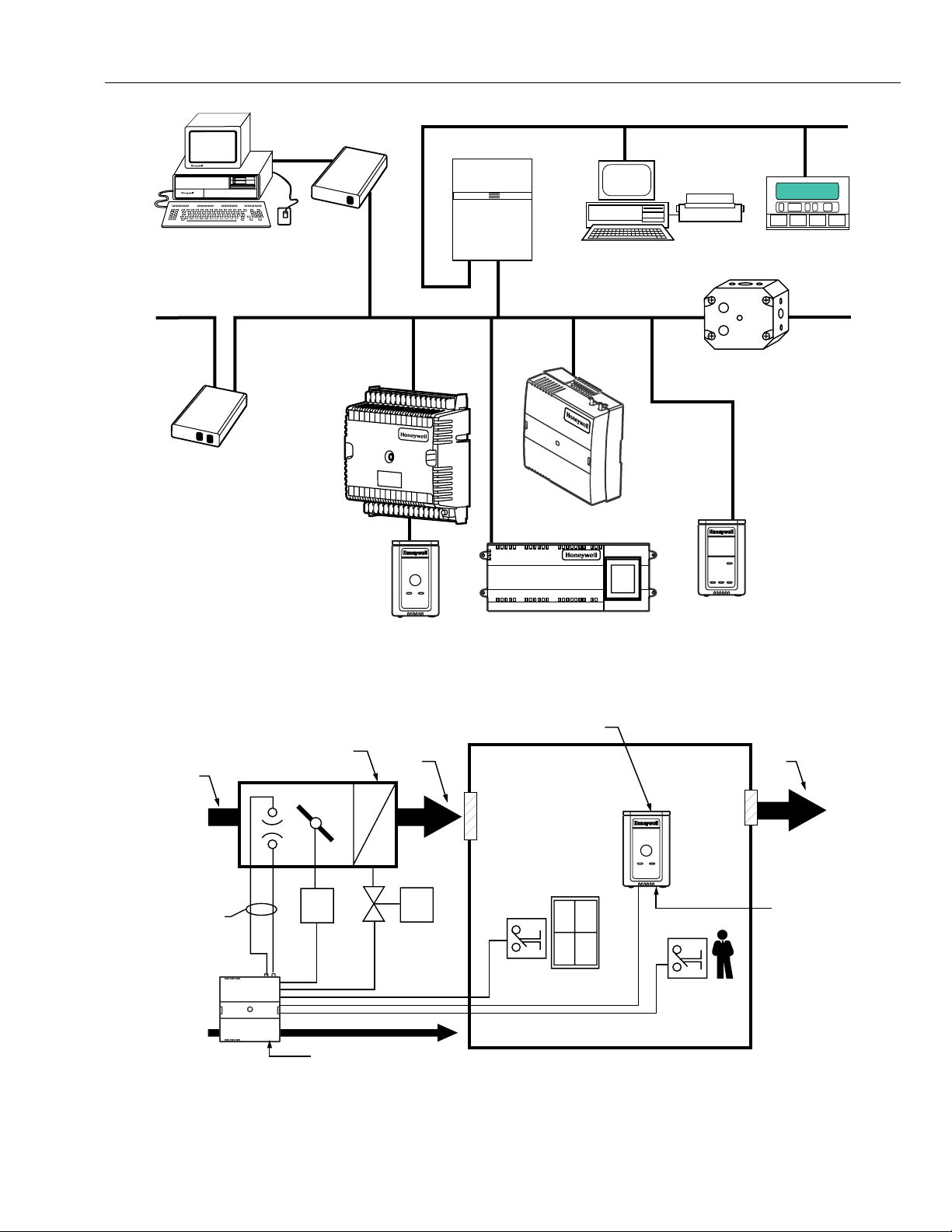
The Q7750A Excel 10 Zone Manager is a communications
interface that allows devices on the E-Bus network to
communicate with devices on the EXCEL 5000® System
C-Bus. Fig. 1 shows an overview of a typical system
layout. The Q7750A also provides some control and
monitoring functions.
&RQWURO$SSOLFDWLRQ
VAV systems in commercial buildings typically incorporate
a central air handler that delivers a modulated volume of
air at a preconditioned temperature to multiple zones.
Each zone is serviced by a VAV terminal box unit. Each
box incorporates an air flow pickup assembly and
motorized damper with optional fan and/or reheat coil. The
controller determines and regulates the air flow of
conditioned air to the space. The zone being fed by the
terminal box will use a T7770 Wall Module or a T7780
DDWM for space temperature determination and access to
the E-Bus network for operators. Fig. 2 shows a typical
VAV box control application for the W7751B,D,F
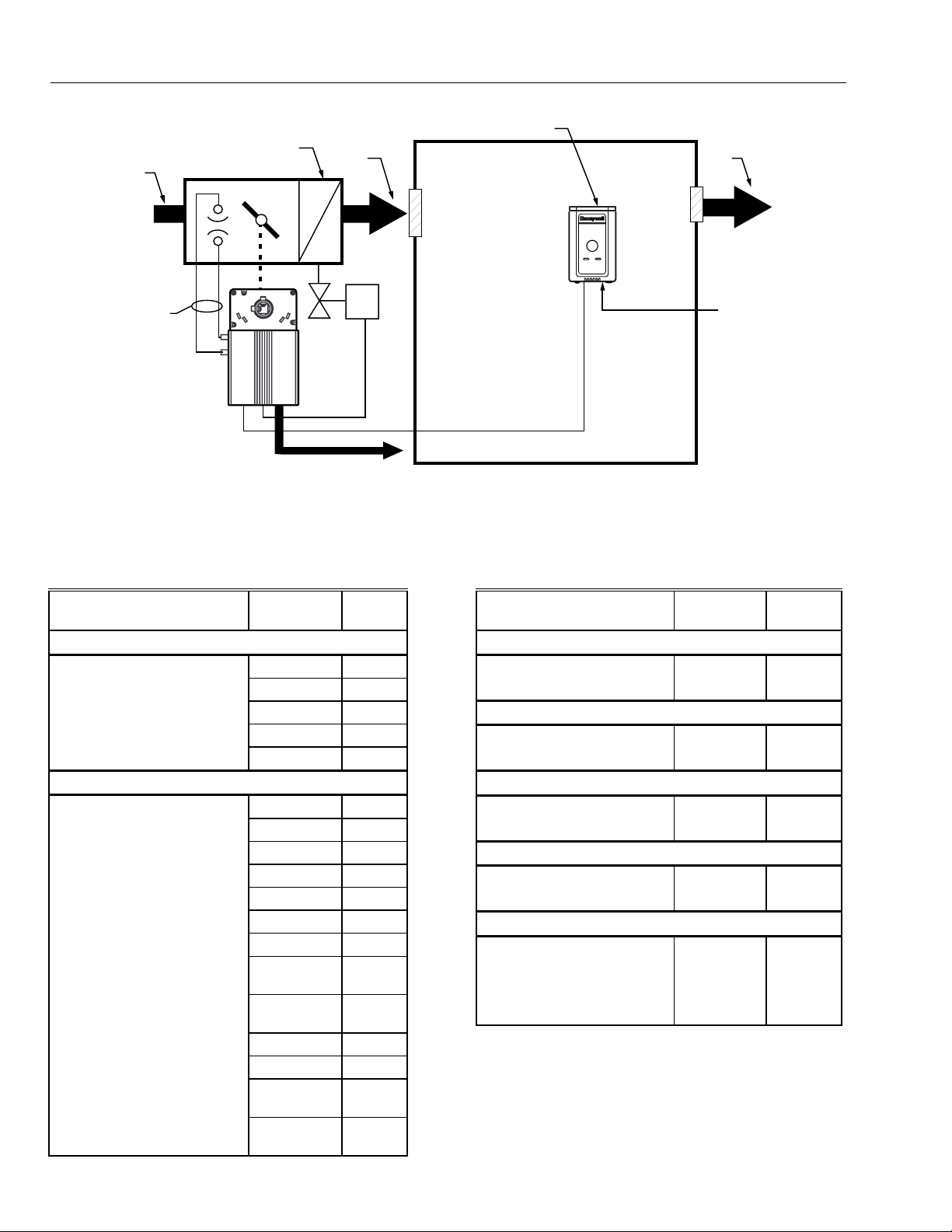
Controllers. Fig. 3 shows a typical VAV box control
application for the W7751H Smart VAV Actuator. Table 1
shows the capabilities of the Excel 10 VAV Box
Controllers.
74-2949–1 4
Page 5
EXCEL 10 W7751B,D,F,H VAVII CONTROLLERS
PERSONAL COMPUTER TOOLS
E-VISION
CARE
FTT E-BUS COMMUNICATIONS NETWORK
EXCEL 10
Q7751A
FTT
E-BUS
ROUTER
W7750B
CVAHU
CONTROLLER
EXCEL 10 T7770
WALL MODULE
Q7752A
FTT E-BUS
SERIAL
ADAPTER
31 30 29 28 27 26 25 24 23 22 21 20 19 18 17 16
1234567 89101112131415J3
C-BUS COMMUNICATION NETWORK
EXCEL 10
Q7750A
FTT ZONE
MANAGER
C-BUS TO E-BUS
INTERFACE DEVICE
FTT E-BUS COMMUNICATIONS NETWORK
EXCEL 10
W7752 FTT
FAN COIL UNIT CONTROLLER
EXCEL BUILDING SUPERVISOR
FTT E-BUS
COMMUNICATIONS
NETWORK
EXCEL 10 W7751F
PANEL PLENUM
MOUNT VERSION
VARIABLE AIR
VOLUME
CONTROLLER
EXCEL 500
Q7740A
2-WAY
REPEATER
EXCEL 10 T7780
DIGITAL DISPLAY
WALL MODULE
PRIMARY
AIR
∆P
PICKUP
TERMINAL HEAT
AIR TERMINAL UNIT
M1
Fig. 1. Typical system overview.
ECHELON BUS
DISCHARGE
AIR
M2
TEMPERATURE SENSOR WITH
REMOTE SETPOINT ADJUSTMENT
AND UNOCCUPIED BYPASS
OVERRIDE BUTTON
WINDOW CONTACT
OCCUPANCY
CONTACT
RETURN
AIR
E-BUS
NETWORK
ACCESS
M11817
EXCEL 10 VAV
CONTROL MODULE W7751
E-BUS NETWORK ACCESS
Fig. 2. Typical W7751B,D,F VAV box control application.
M1 = DAMPER ACTUATOR
M2 = VALVE ACTUATOR
M11818
5 74-2949–1
Page 6
EXCEL 10 W7751B,D,F,H VAVII CONTROLLERS
PRIMARY
AIR
TERMINAL HEAT
AIR TERMINAL UNIT
DISCHARGE
AIR
TEMPERATURE SENSOR
WITH REMOTE SETPOINT
ADJUSTMENT
RETURN
AIR
∆P
PICKUP
EXCEL 10
W7751G
SMART VAV
ACTUATOR
M1-REHEAT
VALVE
ACTUATOR
E-BUS
M1
E-BUS
NETWORK
ACCESS
M11819
Fig. 3. Typical W7751H Smart VAV Actuator box control application (Smart VAV Actuator mounts directly on the
damper shaft as represented by the dotted line). (The W7751H does not include a window contact or occupancy
sensor contact terminals, which are available via the network only.)
Table 1. Excel 10 VAV Box Controller Capability.
Excel 10 VAV Box Controller
Capability W7751B,D,F W7751H
Fan
None X X
Series X X
Parallel - Temp X X
Parallel - Flow X X
Parallel - PWM
XX
Reheat
None X X
One Stage Reheat X X**
Two Stages Reheat X X**
Three Stages Reheat X —
One Stage Periph X X**
Floating Reheat (Two outputs) X X**
Floating Periph (Two outputs) X X**
Floating Reheat then Periph
X—
(Four outputs)
Floating Periph then Reheat
X—
(Four outputs)
Excel 10 VAV Box
Controller Capability W7751B,D,F W7751H
Exhaust Tracking
Disabled X X
Enabled X X
Occupancy Sensor
None X X
Connected X —*
Window Contact
None X X
Connected X —*
Wall Module Configuration
Local X X
Shared X X
Wall Module Type
Sensor Only X X
Sensor and Setpoint X X
Sensor, Setpoint and Bypass X X
Sensor and Bypass X X
PWM Reheat (One output) X X**
PWM Periph (One output) X X**
PWM Reheat then Periph
XX**
(Two outputs)
PWM Periph then Reheat
XX**
(Two outputs)
(continued)
74-2949–1 6
Page 7
EXCEL 10 W7751B,D,F,H VAVII CONTROLLERS
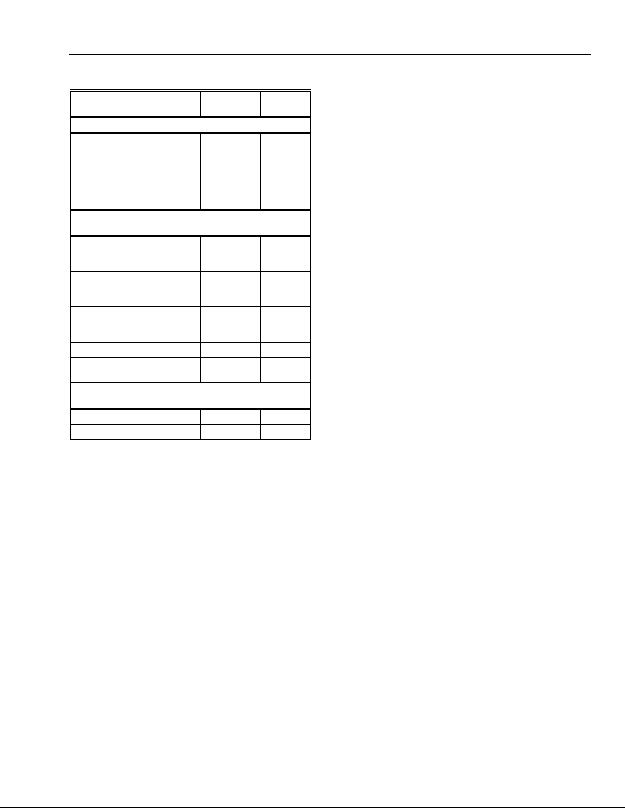
Table 1. Excel 10 VAV Box Controller Capability
Excel 10 VAV Box
Controller Capability W7751B,D,F W7751H
Air Temperature Sensor
20 K ohm air temperature
sensors can be used in
conjunction with wall modules
(Either a wall module or an air
temperature sensor can be
used with the W7751H, but
not both.)
Dual Duct Pressure
Independent
Flow mixing
Cold and hot duct flow
pickups
Without flow mixing
Cold and hot duct flow
pickups
Constant volume
Cold and hot duct flow
pickups
With cold duct pickup only X X
Constant volume with
discharge pickup only
Dual Duct Pressure
Dependent
With flow mixing X X
Without flow mixing X X
* Available only via the network for the W7751H.
** The W7751H Smart VAV Actuator provides damper
control and two configurable outputs available for
two stages of reheat, floating reheat (requires two
outputs), PWM Reheat or Periph (one output
required), PWM Reheat and Periph (two outputs
required) or one stage of reheat or Periph (can be
PWM also) and a serial or parallel fan.
*** These applications require two W7751 Excel 10
controllers per zone.
**** Flow sensor in discharge air. The temperature
control loop controls the cool damper position and
the flow controls adjust the heating damper position.
(Continued).
XX
X*** X***
X*** X***
X*** X***
X**** X****
&RQWURO3URYLGHG
The W7751B,D,F,H Controllers are primarily intended for
pressure independent, single or dual-duct VAV box
control. Pressure independent control specifies that the
individual zone terminal unit has a means for maintaining a
consistent volume of air into the zone regardless of the
input static pressure. The controller modulates the air flow
into the zone to satisfy the Zone Temperature Setpoint.
Minimum Air Flows are maintained except during
emergency strategy periods or during building Unoccupied
periods if using physical position stops, a MIN/MAX air flow
is always maintained (see Table 2).
Pressure dependent control specifies that the damper
position is controlled by space temperature only and not by
a measurement of air flow volume. The amount of air
delivered to the zone at any given damper position is
dependent on the static pressure in the supply air duct
(physical position stops, range stop pins, are used to keep
the damper at a fixed position).
VAV systems generally only provide cool air to the zones;
therefore, the W7751 Controller provides additional
outputs for control of heating systems such as reheat coils
for Heat mode or Morning warm-up mode operation. The
heating equipment can be staged-resistive heating, staged
2-position (solenoid) valve, or modulated steam or hot
water valve.
The possible modes of operation are listed in Table 2.
7 74-2949–1
Page 8

EXCEL 10 W7751B,D,F,H VAVII CONTROLLERS
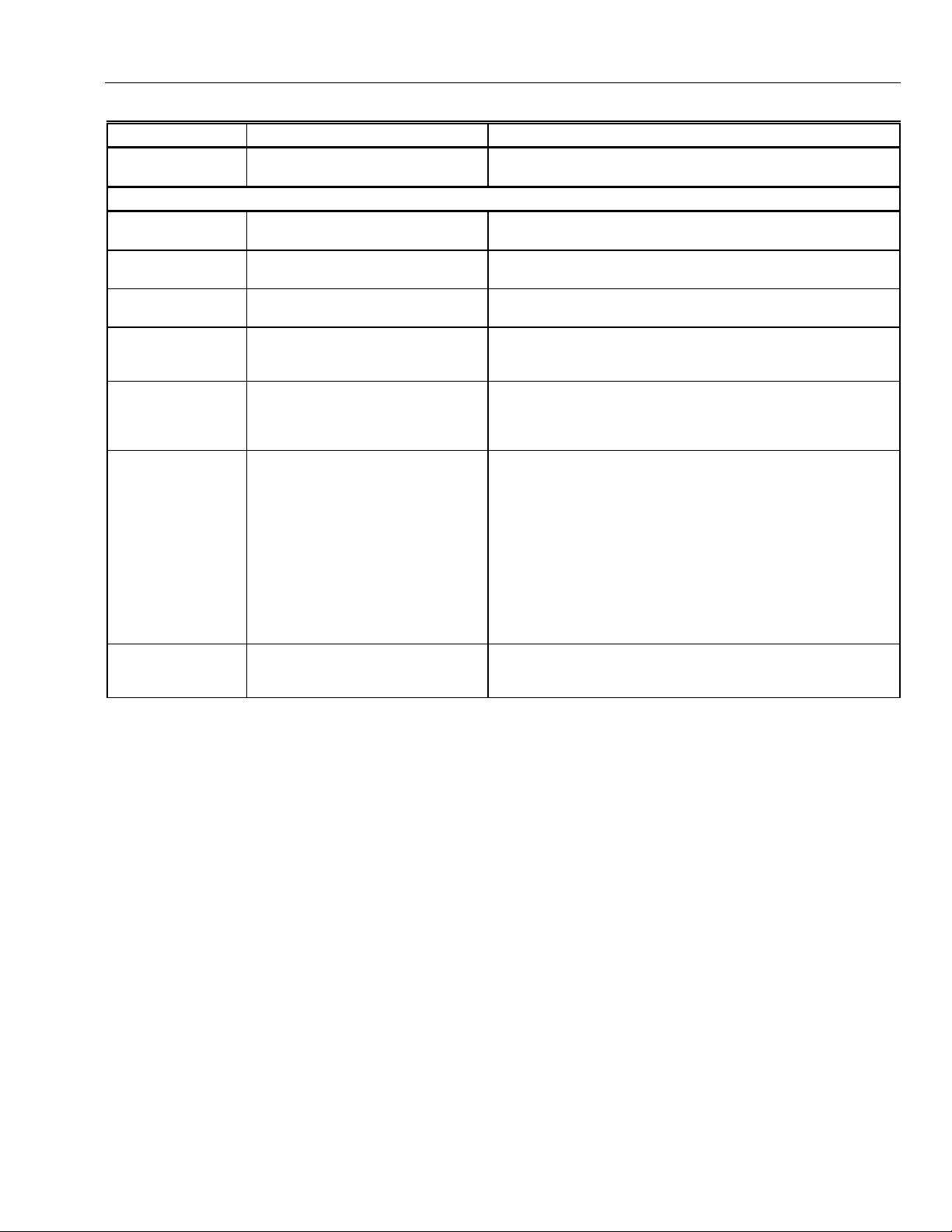
Table 2. Modes Of Operation For Excel 10 VAV Controller.
Mode Description Events Causing a Controller to Switch to This Mode
Effective Occupancy (User Address: StatusOcc)
OCCUPIED* Controller is in Occupied mode. Any of the following: Network input (DestSchedOcc) containing
STANDBY* Controller is in Standby mode. Network input (DestSchedOcc) containing time-of-day schedule
UNOCCUPIED Controller is in Unoccupied mode. Network input (DestSchedOcc) containing time-of-day schedule
Override Modes (User Address: StatusOvrride)
OCCUPIED* Controller is in Occupied mode. Network input (DestSchedOcc) containing time-of-day schedule
UNOCCUPIED Controller is in Unoccupied mode. Network input (DestSchedOcc) containing time-of-day schedule
BYPASS User-initiated Bypass of the
NOT ASSIGNED No Bypass action. No Override input received.
Operational Modes (User Address: StatusMode)
START-UP AND
WAIT (followed by)
FLOAT_OUT_SYNC
COOLING The Excel 10 VAV Controller is
HEATING The Excel 10 VAV Controller is
REHEAT The Excel 10 VAV Controller is
MORNING
WARM-UP
NIGHT PURGE The main AHU is supplying fresh
PRESSURIZE The box damper is set at
DEPRESSURIZE The box damper is set at
FLOW TRACKING Temperature control is turned off.
*Available only via the network for the W7751H.
Unoccupied mode.
Flow Diversity on power-up provides
a staggered start sequence to evenly
apply the load to the supply fan and
electrical system.
controlling the Cooling mode.
controlling the Heating mode.
controlling the Reheating mode.
The main AHU is supplying warm air,
and the box damper is set at
(WarmupDmprPos).
(100 percent outdoor) air, and the
box damper is set at
(PurgeDmprPos).
(PressDmprPos).
(DepressDmprPos).
The box maintains a Flow Setpoint
based on the sum of all of the
controllers supplying the zone (the
SrcBoxFlow controller provides other
controllers with DestFlowTrack input).
time-of-day schedule flag from either the Excel 10 Zone
Manager, a C-Bus controller, an Occupancy Sensor Digital Input,
or from Network input (DestManMode) for manual override to
OCCUPIED mode.
flag from the Excel 10 Zone Manager must be OCCUPIED and
the Occupancy Sensor Digital Input must be UNOCCUPIED.
flag from the Excel 10 Zone Manager, the C-Bus, or the network
input CmdManOcc has a value of UNOCCUPIED.
flag from the Excel 10 Zone Manager, the C-Bus, the Occupancy
Sensor Digital Input or from the Network input (DestManMode)
for manual override to OCCUPIED mode.
flag from the Excel 10 Zone Manager, the C-Bus, or the network
input DestManualOcc has a value of UNOCCUPIED.
Digital input (Bypass pushbutton) has been pressed, and the
Bypass duration timer has not yet expired, or the network input
DestManualOcc has a value of BypassTime.
These modes occur on controller power-up, and after
downloading to the controller from E-Vision or going to auto
mode to manual mode (DestManMode). Temperature and flow
control loops are disabled.
Network input (DestHvacMode) containing AHU operational
mode information from other E-Bus controllers that have the
value of COOL/AUTO.
Network input (DestHvacMode) containing AHU operational
mode information from other E-Bus controllers that have the
value of HEAT/AUTO.
Network input (DestHvacMode) has the value of AUTO, so that
when cool air is supplied to the box and the space temperature is
below the Heating Setpoint, causes the Excel 10 VAV Controller
control algorithm to energize the Reheat coil(s).
Network input (DestHvacMode) containing AHU operational
mode information from E-Bus controllers that have the value of
MORNING WARM-UP.
Network input (DestHvacMode) containing AHU operational
mode information from E-Bus controllers that have the value of
NIGHT PURGE.
Network input (DestHvacMode) containing smoke control signal
from E-Bus controllers that have the value of PRESSURIZE.
Network input (DestHvacMode) containing smoke control signal
from E-Bus controllers that have the value of DEPRESSURIZE.
Configuration parameter is box type (Flow_Tracking).
NOTE: See Fig. 45.
FlowTrackOfst (Flow Offset) determines the differential between
the boxes that are the supply air flow and the exhaust air flow.
(continued
)
74-2949–1 8
Page 9
EXCEL 10 W7751B,D,F,H VAVII CONTROLLERS
Table 2. Modes Of Operation For Excel 10 VAV Controller (Continued).
Mode Description Events Causing a Controller to Switch to This Mode
MANUAL POSITION Box damper is set to (ManDamp). Typically this is done through E-Vision or XBS by setting the
Operational Modes (User Address: StatusMode)
MANUAL FLOW Air Flow Setpoint is set to
MANUAL See comments for FlowManState in
CLOSED* Indicates a window is open; box
SELF TEST Control algorithm is disabled; various
I/O TEST Control algorithm is disabled, various
FLOAT_OUT_SYNC Controller is synchronizing actuators. Control loops are temporarily suspended. NOTE: For controllers
(DestManFlowSpt).
Appendix D,
damper is set to (WinOpnDmprPos).
hardware tests can be performed.
hardware tests can be performed
(see I/O Test Mode, Application Step
7. Troubleshooting).
Table D7. LonMark®.
point DamperPos to Manual mode.
Typically this is done through E-Vision or XBS by setting the
point SupplyFlow to Manual mode.
The (Window) Digital Input contacts are open and the controller
is configured for a window sensor.
The variable (TestMode) was set to TESTING. NOTE: This mode
is available in Excel 10 VAV Controller versions and also include
the W7751H Smart VAV Actuator.
The I/O test pin/pad is shorted (see the I/O Test Mode,
Application Step 7. Troubleshooting).
NOTE: The I/O Test Mode is not available on the W7751H
Smart VAV Actuator.
that enter the Unoccupied mode, its actuators are controlled and
resynchronize during a time frame of 125 percent of the
actuators motor speed; for example, if an actuators motor speed
is 90 seconds, the actuator would resynchronize after 112
seconds once its controller entered the Unoccupied mode.
If a controller remains in continuous Occupied mode, the
actuators that it controls resynchronize approximately once every
24 hours based on the CPU clock of the controller. If a controller
remains in continuous Occupied mode it resynchronizes
randomly during this time period of one hour.
DISABLED Shutoff control algorithm Network input (DestManMode) containing AHU operational mode
*Available only via the network for the W7751H.
3URGXFWV&RYHUHG
This System Engineering Guide describes how to apply
the Excel 10 family of W7751 VAV Controllers and related
accessories to typical applications. The specific devices
covered include:
W7751B,D,F,H Controllers.
•
T7770A through D Wall Modules.
•
T7780 Digital Display Wall Module.
•
Q7750A Excel 10 Zone Manager.
•
Q7751A,B Bus Router.
•
Q7752A Serial Adapter.
•
Q7740A,B FTT Repeaters.
•
209541B FTT Termination Module.
•
information from other E-Bus controllers that have the value of
DISABLED.
2UJDQL]DWLRQRI0DQXDO
This manual is divided into three basic parts: the
Introduction, the Application Steps, and the Appendices
that provide supporting information. The Introduction and
Application Steps 1 through 5 provide the information
needed to make accurate material ordering decisions.
Application Step 6 and the Appendices include
configuration engineering that can be started using Excel
E-Vision PC Software after the devices and accessories
are ordered. Application Step 7 is troubleshooting.
The organization of the manual assumes a project is being
engineered from start to finish. If an operator is adding to,
or is changing an existing system, the Table of Contents
can provide the relevant information.
9 74-2949–1
Page 10

EXCEL 10 W7751B,D,F,H VAVII CONTROLLERS
$SSOLFDEOH/LWHUDWXUH
The following list of documents contains information
related to the Excel 10 family of VAV Box Controllers and
the EXCEL 5000® System in general.
Form No. Title
74-2076C Excel 10 Technical Literature Collation
74-2942 Excel 10 W7751B,D,F Controller
Specification Data
74-2953 Excel 10 W7751H Smart VAV Actuator
Specification Data
74-2697 T7770A through G Wall Module
Specification Data
74-2955 T7780 Digital Display Wall Module
Specification Data
74-2868 Excel 10 C7770A Air Temperature Sensor
Specification Data
74-2950 Excel 10 Q7750A, Zone Manager
Specification Data
74-2952-1 Excel 10 Q7751A,B Router Specification
Data
74-2954-1 Excel 10 Q7752A Serial Interface
Specification Data
74-2858 Excel 10 Q7740A,B FTT Repeaters
Specification Data
74-2951 Excel 10 Q7750A Zone Manager Checkout
and Test Manual
95-7504 Excel 10 W7751B,D,F Controller
Installation Instructions
95-7538 T7770A,B,C,D,E,F,G Wall Module
Installation Instructions
95-7558 T7780 Digital Display Wall Module
Installation Instructions
95-7509 Excel 10 Q7750A Zone Manager
Installation Instructions.
95-7510 Excel 10 Q7751A,B Router Installation
Instructions
95-7511 Excel 10 Q7752A Serial Interface
Installation Instructions
95-7516 Excel 10 SLTA Connector Cable Installation
Instructions
95-7555 Excel 10 Q7740A,B FTT Repeaters
Installation Instructions
95-7554 Excel 10 209541B Termination Module
Installation Instructions
74-2588 Excel E-Vision User’s Guide
74-5587 CARE User’s Manual
74-1392 CARE Excel 10 Zone Manager User’s
Guide
74-5577 CARE Icon Guide
74-2039 XBS User’s Manual
74-5018 XBS Application Guide
3URGXFW1DPHV
The W7751 Controller is available in four models:
W7751B VAV Box Controller for OEM mounting on a
•
VAV box.
W7751D VAV Box Controller mounts on either a
•
standard 4 in. by 4 in. electrical junction box or a
standard 5 in. by 5 in. electrical junction box (wire
passes through junction box to wiring subbase). It can
also be snapped onto standard EN 50 022 DIN rail 35
mm by 7.5 mm (1-3/8 in. by 5/16 in.).
W7751F VAV Box Controller mounts into either a panel
•
with screws or snaps onto standard EN 50 022 DIN rail
35 mm by 7.5 mm (1-3/8 in. by 5/16 in.). Wires are
terminated externally to wiring subbase.
W7751H Smart VAV Actuator is a VAV controller that is
•
factory mounted to an ML6161B1000 Actuator. The
actuator/controller assembly is field mounted to the
VAV box damper shaft similar to the mounting of a
standard actuator, and the controller wiring is
terminated to the screw terminals that are located under
a snap-on cover.
The T7770 Wall Module is available in five models:
T7770A1006 Wall Module with temperature sensor.
•
Use with Excel 5000 or Excel 10 Controllers.
T7770A2004 Wall Module with temperature sensor and
•
E-Bus network connection. Use with Excel 5000 or
Excel 10 Controllers.
T7770B Wall Module with temperature sensor, setpoint,
•
and E-Bus network connection. Use with Excel 5000 or
Excel 10 Controllers.
T7770C Wall Module with temperature sensor, setpoint,
•
Bypass button and LED, and E-Bus network
connection. Use with Excel 5000 or Excel 10
Controllers.
T7770D Wall Module with temperature sensor, Bypass
•
button and LED, and E-Bus network connection. Use
with Excel 5000 or Excel 10 Controllers.
NOTE: The T7770B,C Models are available with a
The T7780 DDWM is available in four models:
•
Other products:
• Q7750A Excel 10 Zone Manager.
• Q7751A,B Bus Router.
• Q7752A Serial Adapter.
• Q7740A,B FTT Repeaters
• 209541B FTT Termination Module
• ML6161 Series 60 Damper Actuator.
• M6410A Series 60 Valve Actuator (use with V5812 or
• ML684A Series 60 Versadrive Valve Actuator (use with
• MMC325-010 Transducer, Series 60 to pneumatic 0 to
• MMC325-020 Transducer, Series 60 to pneumatic 0 to
• ML6464A Direct Coupled Damper Actuator, 66 lb.-in.
• ML6474 Direct Coupled Damper Actuator, 132 lb.-in.
• ML6185A Direct Coupled Damper Actuator, Spring
relative scale plate adjustable in E-Vision °F
(± 5°C).
T7780 DDWM displays and provides space
temperature, setpoint, Occ/Unocc override, Application
Mode, and Fan mode/speed selection for all Excel 10
controllers (except W7751A,C,E,G).
V5813 Valves).
V5011 and V5013 Valves).
10 psi.
20 psi.
torque, Series 60.
torque, Series 60.
Return, Series 60.
74-2949–1 10
Page 11

EXCEL 10 W7751B,D,F,H VAVII CONTROLLERS
• ML7984B Direct Coupled Valve Actuator, PWM (use
with V5011 or V5013F,G Valves).
•
EL7680A1008 Wall Module Infrared Occupancy
Sensor.
•
EL7628A1007 Ceiling Mounted Infrared Occupancy
Sensor.
•
EL7611A1003 Ultrasonic Occupancy Sensor.
•
EL7612A1001 Ultrasonic Occupancy Sensor.
•
AK3781 E-Bus (non-plenum): 22 AWG (0.325 mm
2
)
twisted pair solid conductor, non-shielded wire (one
twisted pair).
•
AK3782 E-Bus (non-plenum): 22 AWG (0.325 mm
2
)
twisted pair solid conductor, non-shielded wire (two
twisted pairs).
$JHQF\/LVWLQJV
Table 3 provides information on agency listings for Excel 10 products.
Table 3. Agency Listings.
Device Agency Comments
W7751B,D,F
Controllers
W7751H Smart VAV
Actuator
UL Tested and listed under UL916 (file number E87741).
CSA Listed (LR95329-3).
FCC Complies with requirements in FCC Part 15 rules for a Class A Computing Device.
Operation in a residential area may cause interference to radio or TV reception and require
the operator to take steps necessary to correct the interference.
FCC Complies with requirements in FCC Part 15 rules for a Class B Computing Device.
Operation in a residential area can cause interference to radio or TV reception and require
the operator to take steps necessary to correct the interference.
UL Tested and listed under UL916 (file number E87741).
cUL Tested and listed under UL916 (file number E87741).
CE General Immunity per European Consortium standards EN50081-1 (CISPR 22 Class B)
and EN 50082-1:1992 (based on Residential, Commercial, and Light Industrial).
EN 61000-4-2 IEC 1000-4-2 (IEC 801-2) Electromagnetic Discharge.
EN 50140, EN 50204 IEC 1000-4-3 (IEC 801-3) Radiated Electromagnetic Field.
EN 61000-4-4 IEC 1000-4-4 (IEC 801-4) Electrical Fast Transient (Burst).
•
AK3791 E-Bus (plenum): 22 AWG (0.325 mm
2
) twisted
pair solid conductor, non-shielded wire (one twisted
pair).
•
AK3792 E-Bus (plenum): 22 AWG (0.325 mm
2
) twisted
pair solid conductor, non-shielded wire (two twisted
pairs).
Refer to Table 10 in Application Step 5. Order Equipment
for a complete listing of all available part numbers.
NOTE: The Q7750A Zone Manager is referred to as
(E-Link) in internal software and CARE.
Radiated Emissions and Conducted Emissions.
EN 55022:1987 Class B.
CISPR-22: 1985.
FCC Complies with requirements in FCC Part 15 rules for a Class B Computing Device.
Operation in a residential area may cause interference to radio or TV reception and require
the operator to take steps necessary to correct the interference.
T7770A through D
UL (Not applicable.)
Wall Modules
CSA (Not applicable.)
FCC (Not applicable.)
T7780 DDWM CE Emissions; EN50081-1, EN55022 (CISPR 22 Class B), Immunity 50082-1
UL &cUL Tested and listed under UL916, S8L9 Energy Management Equipment.
FCC Complies with requirements in FCC Part 15 rules for a Class B Computing Device.
11 74-2949–1
(contifnued)
Page 12
EXCEL 10 W7751B,D,F,H VAVII CONTROLLERS
Table 3. Agency Listings (Continued).
Device Agency Comments
Q7750A Excel 10
Zone Manager
Q7751A,B Router,
Q7752A Serial
Adapter
UL Tested and listed under UL916, file number S4804 (QVAX, PAZY).
CSA Listing pending.
FCC Complies with requirements in FCC Part 15 rules for a Class A Computing Device.
Operation in a residential area can cause interference to radio or TV reception and require
the operator to take steps necessary to correct the interference.
UL UL1784.
CSA Listed.
FCC Complies with requirements in FCC Part 15 rules for a Class B Computing Device.
$EEUHYLDWLRQVDQG'HILQLWLRQV
AHU
- Air Handling Unit; the central fan system that
includes the blower, heating equipment, cooling
equipment, ventilation air equipment, and other
related equipment.
Box
- A VAV terminal unit box.
CAV
- Constant Air Volume; a TUC that maintains a
fixed air flow through the box.
CO
- Carbon Monoxide. Occasionally used as a
measure of indoor air quality.
CO
- Carbon Dioxide. Often used as a measure of
2
CARE
C-Bus
CVAHU
DDWM
E-Bus
E-Bus Segment
Echelon®
Economizer
indoor air quality.
- Computer Aided Regulation Engineering; the PC
based tool used to configure C-Bus and E-Bus
devices.
-Honeywell proprietary Control Bus for
communications between EXCEL 5000® System
controllers and components.
CPU
- Central Processing Unit; an EXCEL 5000®
System controller module.
cUL
- Underwriters Laboratories Canada.
-Constant Volume AHU; refers to a type of air
handler with a single-speed fan that provides a
constant amount of supply air to the space it
serves.
DDF
- Delta Degrees Fahrenheit.
-Digital Display Wall Module.
D/X
- Direct Expansion; refers to a type of mechanical
cooling where refrigerant is (expanded) to its cold
state, within a heat-exchanging coil that is
mounted in the air stream supplied to the
conditioned space.
- Honeywell implementation of Echelon®
LonWorks® network for communication among
Excel 10 Controllers.
than 60 Excel 10s. Two segments can be joined
together using a router.
and the Neuron® chips used to communicate on
the E-Bus.
regulate the quantity of outdoor air that enters the
building. In cool outdoor conditions, fresh air can
be used to supplement the mechanical cooling
equipment. Because this action saves energy, the
dampers are often referred to as
dampers
- An E-Bus section containing no more
- The company that developed the LON® bus
- Refers to the mixed-air dampers that
economizer
.
EMI
- Electromagnetic Interference; electrical noise that
can cause problems with communications
E-Link
EEPROM
EPROM
Excel 10 Zone Manager
NOTE: The Q7750A Zone Manager can be referred to as
Firmware
Floating Control
Level IV
OEM
signals.
- Refers to the Q7750A Zone Manager. This name
is used in internal software and in CARE
software.
EMS
- Energy Management System; refers to the
controllers and algorithms responsible for
calculating optimum operational parameters for
maximum energy savings in the building.
- Electrically Erasable Programmable Read Only
Memory; the variable storage area for saving user
setpoint values and factory calibration
information.
- Erasable Programmable Read Only Memory; the
firmware that contains the control algorithms for
the Excel 10 Controller.
interface between the C-Bus and the E-Bus. The
Excel 10 Zone Manager also has the functionality
of an Excel 100 Controller, but has no physical
I/O points.
E-Link in the internal software, CARE.
- Software stored in a nonvolatile memory
medium such as an EPROM.
of a valve or damper. Floating Control utilizes one
digital output to pulse the actuator open, and
another digital output to pulse it closed.
IAQ
- Indoor Air Quality. Refers to the quality of the air
in the conditioned space, as it relates to occupant
health and comfort.
I/O
- Input/Output; the physical sensors and actuators
connected to a controller.
I x R
- I times R or current times resistance; refers to
Ohm’s Law: V = I x R.
K
- Degrees Kelvin.
- Refers to a classification of digital
communication wire. Formerly known as UL Level
IV, but
there is any question about wire compatibility, use
Honeywell-approved cables (see Step 5 Order
Equipment section).
-Original Equipment Manufacturer; the company that
builds the VAV boxes.
- Refers to Series 60 Modulating Control
not
- A controller that is used to
equivalent to Category IV cable. If
74-2949–1 12
Page 13

NEC
- National Electrical Code; the body of standards
NEMA
Node
PWM
Subnet
W7751
Wall Module
for safe field-wiring practices.
- National Electrical Manufacturers Association; the
standards developed by an organization of
companies for safe field wiring practices.
- A Communications Connection on a network; an
Excel 10 Controller is one node on the E-Bus
network.
NV
- Network Variable; an Excel 10 parameter that can
be viewed or modified over the E-Bus network.
PC
- An IBM compatible Personal Computer with 386
or higher processor and capable of running
Microsoft® Windows™ Version 3.1.
Pot
- Potentiometer. A variable resistance electronic
component located on the T7770B,C Wall
Module; used to allow user-adjusted setpoints to
be input into the Excel 10 Controller.
- Pulse W i dth Modulated output; allows analog
modulating control of equipment using a digital
output on the controller.
RTD
- Resistance Temperature Detector; refers to a
type of temperature sensor whose resistance
output changes according to the temperature
change of the sensing element.
- An E-Bus segment that is separated by a router
from its Q7750A Zone Manager.
TOD
- Time-Of-Day; the scheduling of Occupied and
Unoccupied times of operation.
TCU
- Terminal Control Unit; industry can refer to VAV
box controllers such as the Excel 10 VAV
Controller as TCUs.
TUC
- Terminal Unit Controller; industry can refer to
VAV box controllers such as the Excel 10 VAV
Controller as TUCs.
VA
- Volt Amperes; a measure of electrical power
output or consumption as applies to an ac device.
Vac
- Voltage alternating current; ac voltage rather than
dc voltage.
VAV
- Variable Air Volume; refers to either a type of air
distribution system, or to the W7751 Excel 10
VAV Box Controller that controls a single zone in
a variable air volume delivery system.
VOC
- Volatile Organic Compound; refers to a class of
common pollutants sometimes found in buildings.
Sources include out-gassing of construction
materials, production-line by-products, and
general cleaning solvents. A VOC is occasionally
used as a measure of indoor air quality.
-The model number of the Excel 10 VAV Box
Controllers (also see VAV).
- The Space Temperature Sensor and other
optional controller inputs are contained in the
T7770 or T7780 Wall Modules. See Application
Step 5. Order Equipment for details on the
various models of Wall Modules.
XBS
- Excel Building Supervisor; a PC based tool for
monitoring and changing parameters in C-Bus
devices.
EXCEL 10 W7751B,D,F,H VAVII CONTROLLERS
=RQH&RQWURO'HILQLWLRQV
9DULDEOH$LU9ROXPH$78V
Variable air volume (VAV) ATUs are commonly called VAV
boxes. Each VAV box has a controller that controls the
temperature of a room or zone by modulating a damper in
the VAV box to vary the amount of conditioned air supplied
to the zone rather than changing the temperature of the
conditioned air. They are used in larger buildings that have
many zones along with a central air handling fan that
supplies conditioned air via a pressurized main air duct
system. The central air handling fan has a separate
equipment controller that controls discharge air
temperature, humidity, and supply duct static pressure.
$LU7HUPLQDO8QLW&RQWURO
Air terminal units (ATUs) regulate the amount of
conditioned air delivered to satisfy the temperature
requirements of a room or space. ATUs are classified by
air handling system design and are available in several
configurations. ATUs may be of variable air volume or
constant volume design, and may be used in single-duct or
dual-duct air handling systems. ATU controls can be as
basic as a room thermostat controlling a damper or a more
complex direct digital controller operating a damper, a
terminal fan and enabling a reheat coil. In all cases, each
ATU has a controller that is used to control the
environment of the room or space.
3UHVVXUH'HSHQGHQW$QG3UHVVXUH,QGHSHQGHQW
&RQWURO
Static pressure variations in an air handling system can
affect terminal unit operation. Pressure-dependent terminal
units are affected by changing duct static pressures
because their damper position is determined by space
temperature only. They may have mechanical or electric
minimum and maximum air flow limits. Pressureindependent terminal units can automatically adjust to duct
pressure changes because they contain air flow sensors
and the controllers compensate for pressure changes in
the main air distribution system. The damper position in
pressure independent terminal units is determined by both
space temperature and air flow volume.
9DULDEOH$LU9ROXPH$78V9$9
Variable air volume (VAV) ATUs are commonly called VAV
boxes. Each VAV box has a controller that controls the
temperature of a room or zone by modulating a damper in
the VAV box to vary the amount of conditioned air supplied
to the zone rather than changing the temperature of the
conditioned air. They are used in larger buildings that have
many zones along with a central air handling Unit (AHU)
that supplies conditioned air via a pressurized main air
duct system.
13 74-2949–1
Page 14

EXCEL 10 W7751B,D,F,H VAVII CONTROLLERS
6LQJOH'XFW9DULDEOH$LU9ROXPH9$96\VWHPV
Single duct VAV systems are used in over 80 percent of
the VAV applications and employ one main supply air duct
from the central air handling system. The air handling unit
supplies cool air virtually one hundred percent of the time,
with the only exception being a morning warm-up cycle
that is used in buildings that are not continuously
occupied, that temporarily raises the discharge air
temperature of the central air handling system to quickly
warm the building from its unoccupied zone temperatures
to the occupied zone temperatures. Since the central air
handling system is usually supplying cool air, single or
multiple electric reheat coils or a modulating hot water
(hydronic) reheat coil are often added in the VAV box
discharge air duct to reheat the cool air when the zone
becomes too cold. VAV boxes with reheat coils typically
have a series or parallel fan in the VAV box to ensure air
flow across the coil in the heating mode.
3UHVVXUH'HSHQGHQW7KURWWOLQJ9$9%R[HV
Pressure dependent throttling VAV boxes are the simplest
and least expensive ATU. A controller modulates a damper
actuator according to the temperature in the zone. The
pressure dependent VAV box usually has minimum and/or
maximum damper position setpoint stops in the controller
for limiting air volume. Because the unit is pressure
dependent, the volume of air distributed to the zone at any
given space temperature varies with the supply duct static
pressure at the inlet of the VAV box. Maintaining a stable
duct static pressure is important for proper operation and
proper setting of the minimum damper position setpoint
stop is essential for adequate circulation. When reheat
coils and/or finned tube radiation are used the controller
will set the damper position at a minimum position during
the heating mode to ensure some air flow into the space
and optimize heat transfer from the reheat coil. Pressure
dependent VAV boxes are used in smaller buildings or in
areas of larger buildings where the supply duct static
pressure is low and stable.
3UHVVXUH,QGHSHQGHQW9$9%R[HV
Pressure-independent or variable constant-volume VAV
boxes are essentially air flow control devices that deliver a
constant volume of air to a conditioned space at a given
temperature despite a varying supply duct static pressure.
An air flow sensor in the inlet of the VAV box is used to
measure the volume of air and the
resets the air flow volume setpoint as the thermal load
changes in the space
VAV box controller provides two control sequences; zone
temperature control and terminal unit air flow control. The
controller usually has a minimum air flow setpoint to
maintain air flow at light load conditions and a maximum
air flow setpoint to limit the air flow to meet the design
conditions for the zone. A single zone sensor can be used
to control multiple VAV boxes with differing volume ratings.
When reheat coils and/or finned tube radiation are used
with this unit the controller will lower the air flow setpoint
during the heating mode to ensure air flow into the room
and optimize heat transfer from the reheat coil. Pressure
independent VAV boxes are used in buildings with larger
air handling systems that have constant duct static
pressure fluctuations due to the large number of zones.
. Therefore, a pressure independent
VAV box controller
6HULHV)DQ3RZHUHG9$9%R[HV
Series Fan-powered VAV boxes are similar to pressure
dependent and/or pressure independent VAV boxes,
except they include an integral fan in series with the VAV
box discharge duct that recirculates space air at constant
volume and enhances the air distribution in the zone.
Primary air is modulated by the VAV box damper to meet
space demand for cooling and as primary air modulates
down, more plenum air is drawn in by the fan to maintain a
constant discharge volume to the zone. Typically the
series fan is on continuously during occupied hours, or it
can be programmed to be activated as primary air
decreases to ensure adequate air circulation. In addition to
enhancing air distribution, the units serving the perimeter
area of a building usually include a reheat coil that is
sequenced with the primary air damper to supply heat
when required. When the primary air system is not
operating (nighttime or unoccupied control mode), the
night operating mode of the controller enables the fan and
the reheat coil to maintain the lower unoccupied
temperature setpoint in the space. Series Fan Powered
VAV boxes can be pressure independent or pressure
dependent.
3DUDOOHO)DQ3RZHUHG9$9ER[HV
Parallel Fan Powered VAV boxes or Bypass Fan Induction
Terminal Units are similar to Series Fan-powered VAV
terminal units, except the fan is located in the return
plenum and does not run continuously during occupied
hours. When the zone temperature is low and the need for
primary air decreases, the controller modulates the
primary air damper to a minimum and enables the fan,
which recirculates warm air from the return plenum into the
zone acting as the first stage of reheat. If a reheat coil is
used the fan is cycled on when the reheat coil is enabled.
As the space warms, the reheat valve closes and the fan
cycles off as the primary air damper opens to allow
delivery of conditioned air from the air handling system.
When heating is required in the unoccupied mode, the fan
at the central air handling system remains off , the VAV
box fan and the reheat coil are enabled and the zone is
heated to a reduced night setback temperature using air
from the return air plenum. Parallel Fan Powered VAV
boxes can be pressure independent or pressure
dependent.
,QGXFWLRQ9$9%R[HV
Induction VAV boxes use induced return air as the reheat
medium which means no parallel fan is present in the VAV
box. Induction VAV boxes are usually installed above the
ceiling and draw return air from the plenum created by a
false ceiling. The VAV box controller uses an air flow
sensor for controlling air flow and a room sensor for
controlling room temperature similar to pressure
independent VAV boxes. The volume of air coming
through the primary damper is controlled by positioning
both dampers simultaneously so that as the primary air
damper closes, the return air damper opens. Return air is
thus drawn into the unit and recirculated into the space.
Like pressure independent VAV boxes the controller resets
the air flow setpoint of the controller as the thermal load
changes in the conditioned space. For extremely cold
design conditions, a reheat coil can be added.
74-2949–1 14
Page 15

EXCEL 10 W7751B,D,F,H VAVII CONTROLLERS
The induction VAV ATU maintains satisfactory air motion
at lower loads than a throttling VAV box can, however, the
wide use of Parallel Fan Powered VAV boxes has now
limited the use of Induction VAV boxes.
6LQJOH'XFW&RQVWDQW9ROXPH=RQH5HKHDW$LU
7HUPLQDO8QLWV
Single-Duct Constant Volume Zone Reheat Systems are
used in low static pressure systems and have a heating
coil (hot water, steam, or electric) in the branch supply
duct to each zone. The central air-handling unit supplies
constant temperature air and a manual balancing damper
in each zone is set in a fixed position to determine the
amount of air delivered to that zone. The volume of air
delivered to each zone will change as the static pressure
of the supply duct changes, however, in low static pressure
systems the changes in the supply duct static pressure are
small and do not have a dramatic effect on the amount air
delivered to the zone. The control strategy used in single
zone reheat systems is simple and involves activating
electric heat or positioning a valve in conjunction to the
zone temperature. In most cases this is accomplished
using a simple space thermostat. However, direct digital
controllers can be used in these cases to control multiple
zone valve positions the reheat coil valve (or electric
heating elements) as required to maintain space condition.
'XDO'XFW$LU+DQGOLQJ6\VWHPV
In a dual-duct air handling system, supply air is divided at
the central fan and hot air and cold air flow through
separate ducts to the perimeter zones in the building.
Dual-duct terminal units are essentially mixing boxes with
two supply inlets and one discharge outlet. The air is
allowed to mix in the mixing box section and is discharged
out of a single duct into the zone. Since a source of
heating is available reheat coils are not used in the zone.
Basic dual-duct mixing systems were not economical
because supply air was cooled and heated year round and
modern energy codes prohibited their use in many cities in
the U.S. except in critical applications like hospitals,
nursing homes, etc. However, with direct digital controllers
and networked systems the individual zone data can be
used to reset hot and cold duct temperatures as needed,
allowing dual duct systems to be used more often in
todays applications. Dual duct systems are often used in
conjunction with single duct systems in the same building.
9DULDEOH&RQVWDQW9ROXPH=HUR(QHUJ\%DQG
'XDO'XFW9$9%R[HV
Variable Constant Volume (Zero Energy Band) Dual-Duct
VAV Boxes have inlet dampers (with individual damper
actuators and air flow sensors) on the cooling and heating
supply ducts. The air flow is pressure independent and the
Dual Duct VAV Box controller uses the zone temperature
to determine the required flow of hot and cold air from the
respective ducts into the mixing box and resets the hot
duct and cold duct air flow setpoints in sequence as space
load changes. The Zero Energy Band (ZEB) is an energy
conservation technique that allows temperatures to float
between programmable settings to prevent the
consumption of heating or cooling energy while the
temperature is in this range. As space temperature rises to
approach the controller setpoint, the hot air flow volume
drops to zero. If space temperature continues to rise
through the ZEB, the output signal from the controller
modulates the cold-air damper open. The controller
maintains adjustable minimum flows for ventilation, with no
overlap of damper operations, during the ZEB when
neither heating nor cooling is required. For example, if a
zone had a setpoint of 74 degrees and a zero energy band
of 2 degrees then the zone temperature would be allowed
to float between 73 degrees and 75 degrees before the
controller would use hot air to heat the zone or cool air to
cool the zone. When the ZEB technique is properly used
the comfort of the occupants is not sacrificed in the
process of saving energy.
'XDO'XFW&RQVWDQW9ROXPH6\VWHPV
Dual-duct mixing box terminal units
Dual-duct mixing box terminal units generally apply to lowstatic pressure systems that require large amounts of
ventilation. The warm duct damper and the cool duct
damper are linked to operate in reverse of each other from
a single damper actuator. The controller positions the
mixing dampers through a damper actuator to mix warm
and cool supply air to maintain space condition. Discharge
air quantity depends on the static pressure in each supply
duct at that location.
Dual-duct constant volume mixing box terminal units
Dual-duct constant volume mixing box terminal units
typically used on high-static-pressure systems where the
air flow quantity to each space is critical. The units are the
same as those described in the previous paragraph,
except that they include either an integral mechanical
constant volume regulator or an air flow constant volume
control furnished by the unit manufacturer to change the
damper position to maintain a constant air flow volume
with changes in duct static pressure.
are
9DULDEOH9ROXPH9DULDEOH7HPSHUDWXUH997
VVT systems are also called commercial zoning systems
and use a constant volume air supply (roof top unit, heat
pump, small air handler) with heating, cooling and
economizer functions and vary the flow rates and supplyair temperature into smaller, damper-controlled zones
through a single duct distribution system. Each zone
damper is modulated based on space temperature.
However, damper control is based only on zone
temperature and there is no flow control at the zone level
as there is in a pressure independent variable air volume
(VAV) system. Typically, the zone damper is modulated
using an analog signal, providing excellent zone
temperature control. A method of providing feedback of
zone demand is provided which allows a controller at the
rooftop to provide the minimum required amounts of
heating and cooling (using economizer when acceptable)
based on zone demand.
Because a number of zone dampers can possibly be
closed, there needs to be a way to relieve pressure in the
supply duct. A bypass damper is normally added in a duct
between the supply and return ducts to relieve pressure.
The pressure relief damper is normally controlled by
sensing supply duct pressure and opening to vent supply
air directly to return. This is one difference between a
commercial zoning system and true VAV. A true VAV air
handler actually varies air volume through the blower.
15 74-2949–1
Page 16

EXCEL 10 W7751B,D,F,H VAVII CONTROLLERS
VVT makes it possible to operate a single-zone
heating/cooling unit with multiple-zones and is often used
in smaller buildings. Small buildings are not appropriate for
VAV systems because the heating and cooling loads are
not large enough for a VAV system to operate properly.
VVT systems also cost less than VAV systems due to the
use of constant volume packaged units, lower pressure
ductwork, and they often do not require expensive
perimeter heat. The main difference between VAV and
VVT is the fact that VAV systems vary the amount of air
entering a zone and not the temperature, where a VVT
system varies both the amount of air and the temperature
of the air entering the zone.
6LQJOH=RQH5RRIWRS$LU+DQGOLQJ8QLW&RQWURO
&9$+8
Single-zone systems use a Constant Volume Air-Handling
Unit (CVAHU) which are usually factory-packaged units
mounted on the rooftop of the building, however, single
zone air handling units can also be located in a
mechanical room of buildings. Single zone units are used
in smaller buildings, buildings that have a uniform
heating/cooling load in large open zones, or in zones that
have special comfort requirements that are different from
other areas of the building. The building must also have
the space available for the associated air handling
equipment. Typical installations include; office/warehouse
buildings, large open buildings such as supermarkets,
restaurants, and ballrooms and lobbies of large buildings
and hotels. Since single zone units are associated with
only one zone, many single zone air handling units can be
installed in a building. Fan volume control, as found in
Variable Air Volume systems is not required, because fan
volume and duct static pressure are set by the
manufacturer to meet the design needs of the zone.
Temperature and Ventilation Control
A single space controller or thermostat controls the heating
coil, ventilation dampers, and cooling coil in sequence as
thermal load varies in the conditioned space. On rooftop
mounted units the heating coils are typically electric and
the cooling is by a self contained air-conditioning system
using direct expansion cooling coils. However, single zone
air handling systems that are located in a mechanical room
of a building often employ hot water (hydronic) heating
coils and use chilled water coils for cooling. The ventilation
dampers (Outdoor air, Return air, and Exhaust air) are
controlled to use outdoor air for the first-stage cooling
when the conditions are appropriate. When outdoor air
temperature or heat content (enthalpy) rises to the point
that it can no longer be used for cooling, an outdoor air
limit control overrides the signal to the ventilation dampers
and moves them to the minimum ventilation position, as
determined by the minimum positioning switch or the
minimum position setpoint in the controller. Indoor air
quality control is also accomplished with the Single Zone
controller using sensors and control strategies that
increase the minimum position of the outdoor air damper
to allow more fresh air into the building when the indoor air
quality is poor. A zero energy band often separates the
heating and cooling control ranges, thus saving energy.
8QLWDU\(TXLSPHQW&RQWURO
Unitary equipment includes natural convection units,
radiant panels, unit heaters, unit ventilators, fan coil units,
and heat pumps. Unitary equipment does not require a
central fan. Depending on design, unitary equipment may
perform one or all of the functions of HVAC - ventilation,
filtration, heating, cooling, humidification and distribution.
Unitary equipment frequently requires a distribution system
for steam or hot and/or chilled water.
Control of unitary equipment varies with system design.
Typically, a room thermostat provides a signal to a
controlled device to regulate the unit. The unit may use a
day/night thermostat for operation at lower setpoints during
unoccupied hours. If the unit has a fan, a time clock may
be used to turn the fan off at night, and a night thermostat
may be used to control the temperature within night limits.
When DDC control is used all of the thermostat and time
clock functionality is contained in the controller.
&RQVWUXFWLRQ
&RQWUROOHUV
The Excel 10 VAV Controller is available in four different
models. The W7751B circuit board is ready to be snapped
into a section of standard 3.25 in. (82 mm) by 9 in. (228
mm) snaptrack, part number 207912. The W7751B model
is intended for OEM installation on VAV boxes at the
factory. Connections to the wall module terminals
(19 through 23) and the E-Bus communications terminals
(29 and 30) are made at screw terminal blocks.
Connection for access to the E-Bus is provided by
plugging the connector into the communications jack. All
other connections are made with quarter inch (6.35 mm)
quick connects. See Fig. 4.
The W7751D and W7751F models both use the identical
5 in. by 5 in. circuit board contained in the housing cover.
This cover can plug into either the W7751D or F Subbase.
The W7751D Subbase allows screw terminations to be
made on the inside. This subbase either mounts on a
standard 4 in. by 4 in. or a standard 5 in. by 5 in. electrical
junction box. It can also be snapped onto standard
EN 50 022 DIN rail 35 mm by 7.5 mm (1-3/8 in. by
5/16 in.). For W7751D, see Fig. 5. The W7751F Subbase
provides screw terminations to be made on the outside.
This subbase either mounts on a panel with screws or
snaps onto standard EN 50 022 DIN rail 35 mm by 7.5 mm
(1-3/8 in. by 5/16 in.). DIN rail is available through local
suppliers. Wires are attached to screw terminal blocks on
the top and bottom of the subbase. For W7751F,
see Fig. 6.
The W7751H Smart VAV Actuator is a physically smaller
Excel 10 VAV Controller. The controller enclosure, which
contains the controller circuit board, is constructed of a
sheet metal housing and a plastic snap-on cover. The
sheet metal housing is attached at the factory to the
ML6161B Actuator and has two 1/2 in. (13 mm) knockouts
that are compatible with 1/2 in. (13 mm) or 3/4 in. (19 mm)
conduit, see Fig. 7. The actuator on the Smart VAV
Actuator is field mounted to the VAV box damper shaft and
its controller wiring is terminated to screw terminals
located at the bottom under a snap-on cover.
74-2949–1 16
Page 17
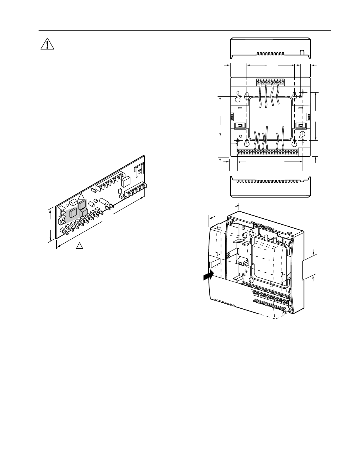
CAUTION
W7751B,D,F Controllers must be mounted
vertically as shown in Fig. 4 through 6. Vertical
mounting assures adequate air flow for proper heat
dissipation in the controller.
The W7751H Smart VAV Actuator is intended for
horizontal shaft mounting only for heat dissipation
needs.
EXCEL 10 W7751B,D,F,H VAVII CONTROLLERS
1-3/32
(28)
4 X 4
MOUNTING
HOLES
3/4
(19)
IMPORTANT
If controller flow sensors are connected to
unusually dusty or dirty environments, a 5-micron
disposable air filter is recommended for use in the
high pressure line (marked as
air flow pickup. This applies to all controller
models. See Table 10 for filter ordering
information.
3
(76)
Fig. 4. W7751B construction in in. (mm).
) connected to the
+
P1
P2
+
∆P
–
1
9 (228)
W7751B
KEEP WIRING ROUTED AWAY FROM THIS HIGH
1
RADIATION AREA TO AVOID INTERFERENCE
PROBLEMS WITH OTHER EQUIPMENT.
M11820
5 X 5
MOUNTING
HOLES
1-1/2
(38)
2-11/32 (60)
1/2
(13)
4-21/32 (118)
3-7/16
(87)
1-3/32
(28)
1-3/8 (35)
DIN RAIL
MOUNTING
SLOT
M11821
Fig. 5. W7751D construction in in. (mm).
17 74-2949–1
Page 18
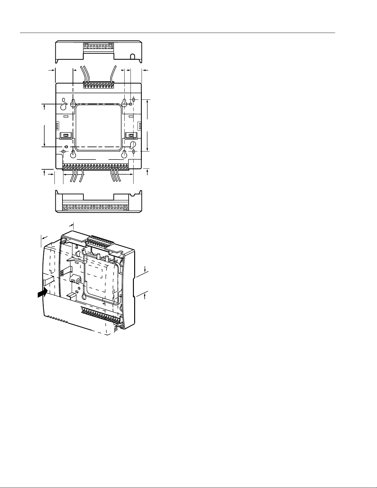
EXCEL 10 W7751B,D,F,H VAVII CONTROLLERS
5 X 5
MOUNTING
HOLES
1-1/2
(38)
2-11/32 (60)
1/2
(13)
1-3/32
(28)
4 X 4
MOUNTING
HOLES
4-21/32 (118)
3/4
(19)
3-7/16
(87)
1-3/32
(28)
1-3/8 (35)
DIN RAIL
MOUNTING
SLOT
M11822
Fig. 6. W7751F construction in in. (mm).
74-2949–1 18
Page 19
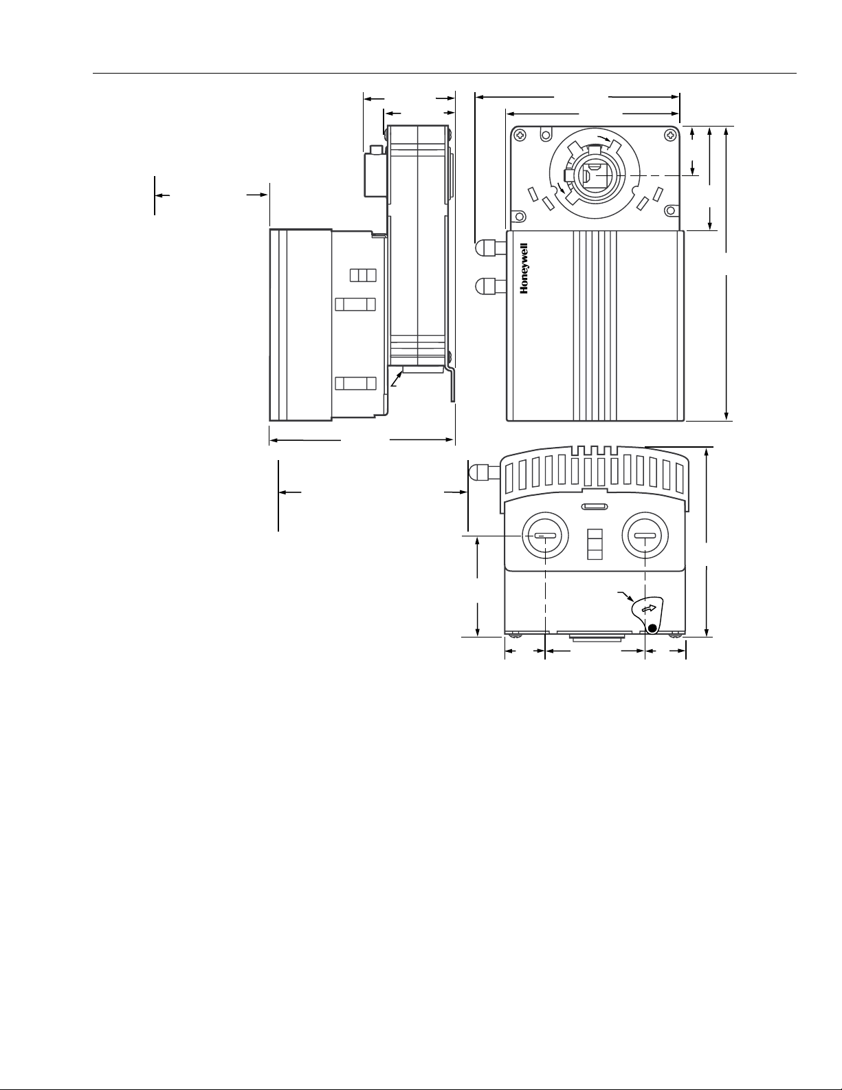
EXCEL 10 W7751B,D,F,H VAVII CONTROLLERS
MAINTAIN A
MINIMUM DISTANCE
OF 3 IN. (76 MM)
FROM OTHER
DEVICES OR PANELS
FOR REMOVING
CONTROLLER COVER
1-13/16 (46)
1-5/16 (33)
DE-CLUTCH
LEVER
3-3/4 (95)
MAINTAIN A MINIMUM DISTANCE
OF 4 IN (100 MM) FROM OTHER
DEVICES OR PANELS FOR
ATTACHING PNEUMATIC AIR
FLOW TUBING
60°
4-1/16 (103)
CCW
CW
45°
3-5/8 (92)
CW
CCW
45°
1
(25)
60°
1-13/16
(46)
5-7/8
(149)
Fig. 7. W7751H construction in in. (mm).
Performance Specifications
Power:
24 Vac with a minimum of 20 Vac and a maximum of 30
Vac at either 50 or 60 Hz.
CPU:
Motorola or Toshiba 3150 Neuron processor, containing
three eight-bit CPU’s. Each Neuron has a unique 48-bit
network identification number.
Memory Capacity:
64K ROM/PROM in W7751B,D,F,H
512 EEPROM
2K RAM
Specified Space Temperature Sensing Range:
45° to 99°F (7° to 37°C) with an allowable control setpoint
range from 50° to 90°F (10° to 32°C) when initiated from
the network and 55° to 85°F (13° to 29°C) when configured
and connected to a T7770 Wall Module or T7780 DDWM.
3-3/4
(95)
2-1/8
(54)
3/4
(19)
DE-CLUTCH
LEVER
1-15/16 (49)
3/4
(19)
M10523
Communications
The W7751B,D,F,H Controller uses a transformer-coupled
communications port with differential Manchester-encoded
data at 78 kilobits per second (kbs). The transformercoupled communications interface offers a much higher
degree of common-mode noise rejection while ensuring dc
isolation.
Approved cable types for E-Bus communications wiring is
Level IV 22 AWG (0.34 mm
2
) plenum or non-plenum rated
unshielded, twisted pair, solid conductor wire. For
nonplenum areas, U.S. part AK3781 (one pair) or U.S. part
AK3782 (two pair) can be used. In plenum areas, U.S. part
AK3791 (one pair) or U.S. part AK3792 (two pair) can be
used (see Tables 9 and 10 for part numbers). Contact
Echelon Corp. Technical Support for the recommended
vendors of Echelon approved cables.
19 74-2949–1
Page 20
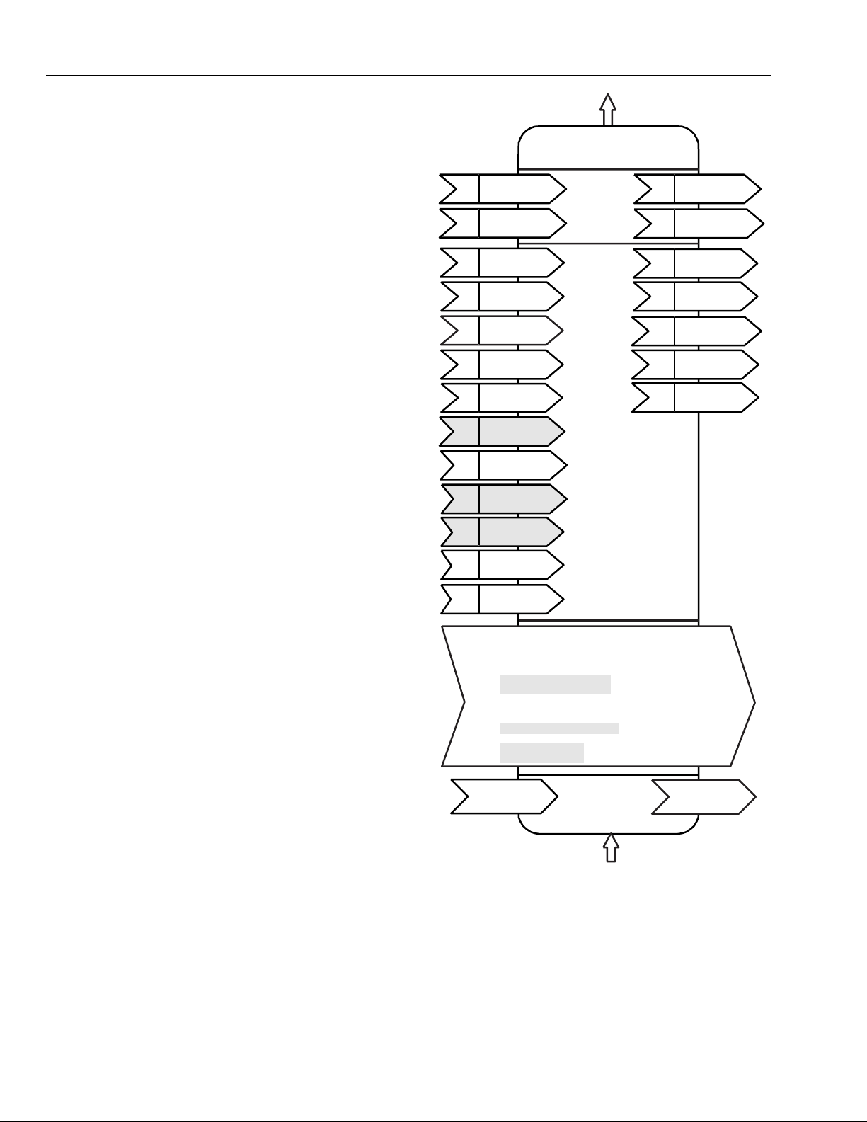
EXCEL 10 W7751B,D,F,H VAVII CONTROLLERS
The FTT supports a polarity insensitive, free topology
wiring scheme that supports star, loop, and/or bus wiring.
The maximum bus length when using a combination of
star, loop, and bus wiring (singly terminated) is 1640 ft
(500m) with the maximum node to node length of 1312 ft
(400m). In the event that the limits on the number of nodes
or total wire length is exceeded, then a 2-way repeater
(Q7740A) can be used to double the node count and the
network length or a 4-way repeater (Q7740B) can
quadruple the node count and the network length. The
maximum number of repeaters per segment is one. A
Q7751A E-Bus Router can also be used to effectively
double the maximum bus length. The advantage of using
the router is that it will segregate traffic to a segment
whereas with the repeater all traffic is repeated on each
segment. On a doubly terminated E-Bus utilizing bus
wiring (continuous daisy-chain with no stubs or taps from
the main backbone) the maximum bus length is 4593 ft
(1400m) with the maximum node to node length of 3773 ft
(1150m).
FTT networks are very flexible and convenient to install
and maintain, but it is imperative, to carefully plan the
network layout, and create and maintain accurate
documentation. Unknown or inaccurate wire run lengths,
node to node distances, node counts, total wire length,
and misplaced or missing terminators can cause poor
network performance. Refer to E-Bus Wiring Guidelines
form, 74-2865 for complete description of network topology
rules.
LonMark Functional Profile
W7751 Controllers support the LonMark Functional
Profile number 8010 VAV Controller, version 1.0
(see Fig. 8).
Environmental
nviSpaceTemp
nv1
SNVT_temp_p
nviSetPoint
nv2
SNVT_temp_p
nviApplicMode
nv5
SNVT_hvac_mode
nviManOverride
nv6
SNVT_hvac_overid
nviSetpointOffset
nv7
SNVT_ temp_p
nviOccCmd
nv8
SNVT_occupancy
nviEnergCmd
nv9
SNVT_hvac_energ
nviBoxFlow
nv10
SNVT_ flow
nviEnergyHoldOff
nv11
SNVT_switch
nviFanSpeed
nv12
SNVT_switch
nviCO2
nv13
SNVT_ppm
nviHeaterOverid
nv14
SNVT_switch
nviDuctIn Temp
nv15
SNVT_temp_p
Hardware
Outputs
VAV Device
Object Type # 8010
Mandatory
Network
Variables
Optional
Network
Variables
nvoSpaceTemp
nv3
SNVT_ temp_p
nvoUnitStatus
nv4
SNVT_hvac_status
nvoEffectSetPt
nv16
SNVT_ temp_p
nvoFlowControlPt
nv17
SNVT_ flow
nvoBoxFlow
nv18
SNVT_ flow
nvoTerminalLoad
nv19
SNVT_lev_percent
nviEnergyHoldOff
nv20
SNVT_switch
Operating Temperature:
-40° to 150°F (-40° to 65.5°C).
Shipping Temperature:
-40° to 150°F (-40° to 65.5°C).
Relative Humidity:
5 percent to 95 percent noncondensing.
Vibration:
Rated V2 level compliant.
Hardware:
The Excel 10 VAV Box Controllers are available in four
models, the W7751B circuit board only, W7751D Plenum
version with internal screw connections an the subbase for
conduit installations, W7751F Plenum version with
external screw connections on the subbase for nonconduit installations, and the W7751H Smart VAV Actuator
which in an Excel 10 VAV Box Controller mounted and
wired to a ML6161B (90 second) actuator.
Configuration Properties
nc49 - Send Heartbeat (mandatory)
nc60 - Occupancy Temperature Setpoints
nc52 - Minimum Send Time
nc17 - Location
nc46 - Duct Area
nc54 - Minimum Flow
nc51 - Maximum Flow (mandatory)
nc55 - Minimum Flow for Heat
nc56 - Minimum Flow Standby
nc57 - Nominal Flow
nc66 - VAV gain
(mandatory)
(optional)nc48 - Maximum Receive Time
(optional)
(optional)
(optional)
(mandatory)
(optional)
(optional)
(optional)
(optional)
Manufacturer
Defined
Section
Hardware
Input
M11823
Fig. 8. Functional profile of LonMark compliant VAV
object details (variables not implemented in Excel 10
VAVII are greyed).
74-2949–1 20
Page 21

EXCEL 10 W7751B,D,F,H VAVII CONTROLLERS
Inputs/Outputs
The W7751B,D,F and H controllers have the following
inputs and outputs:
Analog inputs - 4 total on W7751B,D,F, 3 total on
W7751H.
Space temperature sensor (fixed location) - T7770 A
through D or T7780 DDWM
Duct velocity pressure sensor (fixed location)-
Microbridge 0-2 inch velocity pressure sensor
Configurable analog input options, 2 from the 3 listed
below on W7751B,D,F,
1 from the 3 listed below for
W7751H.
•
Setpoint Potentiometer:
55° to 85°F (13° to 29.5°C) )—(9846 to 1290 ohms).
•
Discharge Air Temperature
Type: RTD (NTC).
Supported Sensors: C7770A1006, C7031C1031,
C7031B1033, C7031J1050.
•
Supply Air Temperature
Type: RTD (NTC).
Supported Sensors: C7770A1006, C7031C1031,
C7031B1033.
NOTE: The C7770 or C7031 Air Temperature Sensors or
Digital Inputs
5 total on W7751B,D,F, 1
the wall module Bypass pushbutton)
are sensed using a 9 milliamp at 4.8 volts detection circuit.
It is very important that the device used contains high
quality, non-corroding contacts with resistivity that does
not degrade; that is, increase over time. Use noble metal
(such as gold or silver), pimpled or sealed contacts to
assure consistent, long-term operation.
•
•
•
the setpoint potentiometer options are selectable
in CARE/E-Vision. (Either one or the other, but
not both are allowed on the W7751H.)
on the W7751H (reserved for
. Dry-contact inputs
Wall Module Bypass Pushbutton—Momentary DI (Fixed
location - See Appendix B—Sequences of Operation for
bypass details.)
Hardware test (Fixed location - not available on the
W7751H).
Three of the following Digital Inputs (DIs) can be
configured when using the W7751B,D,F, (not available
on the W7751H):
Window Monitor—Contact Closed = Window is Closed
Occupancy Switch—Contact Closed = Room is
Occupied; Contact Open = Room is Unoccupied
Heat/Cool change over—Contact Closed = Heat
Monitoring input—Contact Closed = input off or closed
(input reportable on network).
Digital Outputs:
8 total on W7751B,D,F (configurable locations), 4 total on
W7751H (2 fixed position damper outputs and 2
configurable outputs). Configurable digital output options.
Floating damper open (fixed location on W7751H)
Floating damper closed (fixed location on W7751H)
Reheat types
Reheat (floating) valve open
Reheat (floating) valve closed
PWM
Stage 1
Stage 2 or Three stage binary control
Stage 3 (not available on W7751H)
Peripheral Heating types
Peripheral heat (floating) valve open
Peripheral heat (floating) valve closed
PWM
Stage 1
Fan (Series or Parallel)
On/Off
PWM
Auxiliary (On when occupied, Off when unoccupied or
Standby)
Normal (On/Off)
Pulsed (requires two pairs open and closed)
Network (up to 2 outputs commanded from the
network)
Normal (On/Off)
Pulsed (requires two pairs open and closed)
Triac Outputs on the W7751B,D,F Model:
Power ratings: 20 Vac to 30 Vac at 25 mA MIN to 1.0A
MAX current for any voltage.
(For W7751H, a minimum of 25 mA at 20 Vac and a
maximum of 400 mA at 30 Vac.)
CAUTION
When any device is energized by a Triac, the
device must be able to sink a minimum of 25 mA.
NOTE: Triacs sink current to the 24 Vac common
LED:
(For Wall Module LED only) 2.5V at 3 mA.
(terminals 10 on the W7751B model, see Fig. 60,
or terminals 2 and 4 on the W7751D,F models,
see Fig. 66, or terminal 2 on the W7751H model,
see Fig. 72). The controller and all Triac loads
must be wired to the same 24 Vac source.
IMPORTANT:
If non-Honeywell motors, actuators, or
transducers are to be used with Excel 10
Controllers, Triac compatibility must be verified
(see previous NOTE).
:DOO0RGXOHV
The T7770 Wall Module for the Excel 10 Controller is
available in a variety of configurations (see Product Names
section). The models are shown in Fig. 9.
21 74-2949–1
Page 22
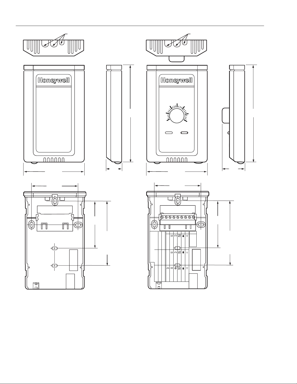
EXCEL 10 W7751B,D,F,H VAVII CONTROLLERS
3-5/32 (80)
KNOCKOUTS FOR EUROPEAN
APPLICATIONS
29/32
(23)
5-1/16
(128)
60
55
65
3-5/32 (80)
70
KNOCKOUTS FOR EUROPEAN
APPLICATIONS
75
80
85
1-1/4
(32)
5-1/16
(128)
2-3/8 (60)
2-3/8 (60)
2-3/8
(60)
STANDARD
UTILITY
CONDUIT
BOX (2 X 4)
MOUNTING
HOLES
9 8 7 6 5 4 3 2 1
W7752
DIP Switch S4 Settings:
XL600-XL20
LED
LED
LED RETURN
SETPT
SENSOR
GND
BYPASS/FAN BYPASS/FAN
SETPT
SENSOR
AL COM
T7770A1006
W7753
BYPASS
LED
FAN
SETPT
SENSOR
1,3,5=on; 2,4=off 2,4=on; 1,3,5=off 1,2,3,4=on; 5=0ff
GND
Fig. 9. T7770A,B,C,D construction in in. (mm) sensor only.
E-BUS
E-BUS
T7770C
2-3/8
(60)
STANDARD
UTILITY
CONDUIT
BOX (2 X 4)
MOUNTING
HOLES
M15119
74-2949–1 22
Page 23
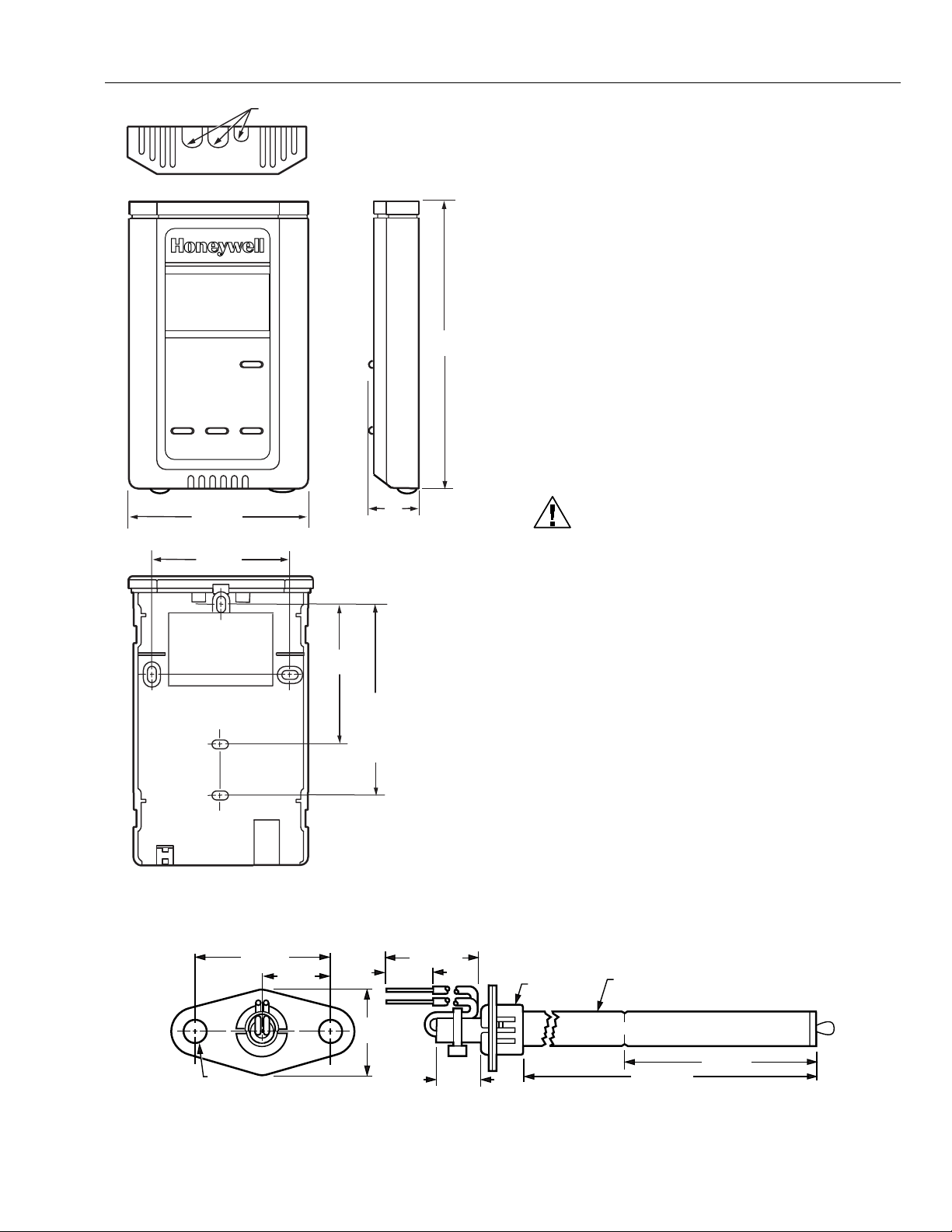
EXCEL 10 W7751B,D,F,H VAVII CONTROLLERS
3-5/32 (80)
2-3/8 (60)
KNOCKOUTS FOR EUROP EAN
APPLICATIONS
2-3/8
(60)
STANDARD
UTILITY
CONDUIT
BOX(2 BY 4)
MOUNTING
HOLES
1
(25)
5-1/16
(128)
6HQVRU'XFW0RXQW
The C7770A Air Temperature Sensor is used for duct
temperature sensing with Excel 10 Controllers (see
Product Names section). The C7770A Air Temperature
Sensor is shown in Fig. 11.
&RQILJXUDWLRQV
*HQHUDO
Table 4 provides an overview of the Excel 10 VAV
Controller configuration options. All VAV boxes are
assumed to have an air flow pickup for connecting to the
Microbridge flow through pressure sensor on the Excel 10
VAV Controller. Also, each box must have a flowregulating damper that is controlled by a Series 60
(floating) type actuator such as the Honeywell ML6161 or a
PWM type actuator. Table 5 lists the general mechanical
equipment options available with the W7751 VAV Box
Controller. See Table 1 for Excel 10 VAV Box Controller
capabilities. See Application Step 6. Configure Controllers
for further information on configurations.
CAUTION
The Excel 10 VAV Controller is designed to work
with Series 60 (floating) Damper Actuators that
have a full stroke damper actuator time between 20
and 600 seconds (0.333 to 10 minutes) or PWM
Damper Actuators that have a minimum time (zero
percent) of 0.1 second and a maximum overall time
of 600 seconds (0.1 second to 10 minutes).
The W7751H Excel 10 VAV Controller is designed
to work only with the Series 60 (floating) Damper
Actuator (ML6161B) that has a full stroke damper
actuator time of 90 seconds.
M11751
Fig. 10. T7780 construction in in. (mm) sensor.
1-1/2 (38)
3/4 (19)
1/4 (6)
DIAMETER (2 HOLES)
7/8
(22)
8-1/2 (216)
1/2 (13)
Fig. 11. C7770A construction - in. (mm).
1/2 (13)
1/2 IN. (13)
DIAMETER
3/8 IN. (10)
DIAMETER
6-5/32 (156)
3-1/2 (89)
M7724
23 74-2949–1
Page 24
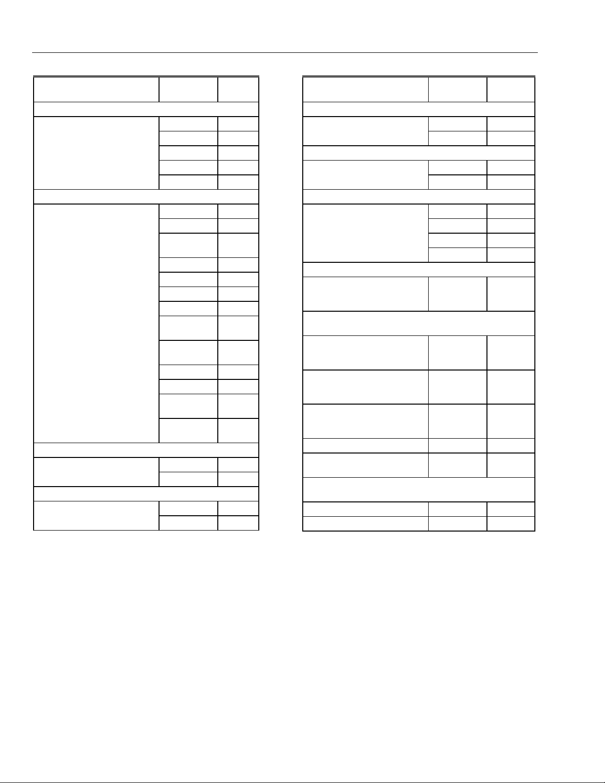
EXCEL 10 W7751B,D,F,H VAVII CONTROLLERS
Table 4. Excel 10 VAV Box Controller Capability.
Excel 10 VAV Box
Controller Capability W7751B,D,F W7751H
Fan
None X X
Series X X
Parallel Temp X X
Parallel Flow X X
Parallel PWM X X
Reheat
None X X
One Stage Reheat X X**
Two Stages or Three Stage
Binary Control Reheat
Three Stages Reheat X —
One Stage Periph X X**
Floating Reheat (Two outputs) X X**
Floating Periph (Two outputs) X X**
Floating Reheat then Periph
(Four outputs)
Floating Periph then Reheat
(Four outputs)
PWM Reheat (One output) X X**
PWM Periph (One output) X X**
PWM Reheat then Periph
(Two outputs)
PWM Periph then Reheat
(Two outputs)
Exhaust Tracking
Disabled X X
Enabled X X
Occupancy Sensor
None X X
Connected X —*
XX**
X—
X—
XX**
XX**
Excel 10 VAV Box
Controller Capability W7751B,D,F W7751H
Window Contact
None X X
Connected X —*
Wall Module Configuration
Local X X
Shared X X
Wall Module Type
Sensor Only X X
Sensor and Setpoint X X
Sensor, Setpoint and Bypass X X
Sensor and Bypass X X
Air Temperature Sensor
20 K ohm air temperature
sensors can be used in
conjunction with wall modules
Dual Duct Pressure
Independent
Flow mixing
Cold and hot duct flow
pickups
Without flow mixing
Cold and hot duct flow
pickups
Constant volume
Cold and hot duct flow
pickups
With cold duct pickup only X X
Constant volume with
discharge pickup only
Dual Duct Pressure
Dependent
With flow mixing X X
Without flow mixing X X
XX
X*** X***
X*** X***
X*** X***
X**** X****
* Available only via the network for the W7751H.
** The W7751H Smart VAV Actuator provides damper control and two configurable outputs available for 2 stages of
reheat, floating reheat (requires two outputs), PWM Reheat or Periph (requires one output), PWM Reheat and Periph
(requires two outputs) or 1 stage of reheat or Periph (an be PWM) and a serial or parallel fan.
*** These applications require two W7751 Excel 10 controllers per zone.
**** Flow sensor in discharge air. The temperature control loop controls the cool damper position and the flow controls
adjust the heating damper position.
74-2949–1 24
Page 25

Option
Fan
Type of
Reheat Coil
Type of
Peripheral
Heat*
Window Open
Option
Monitor switch
Option
Occupancy
Sensor Option
Heat/Cool
change over
switch Option
Wall Module
Option
Wall Module
Type
EXCEL 10 W7751B,D,F,H VAVII CONTROLLERS
Table 5. Configuration Options Summary For W7751 Controllers.
Possible Configurations for the W7751B,D,F
1. None 1. None
2. Parallel Temperature 2. Parallel Temperature
3. Parallel Flow 3. Parallel Flow
4. Parallel PWM 4. Parallel PWM
5. Series 5. Series
1. One stage 1. One stage
2. Two stages or Three Stage Binary 2. Two stages or Three Stage Binary
3. Three stages 3. Series 60 Modulating electric valve, or pneumatic
4. Series 60 Modulating electric valve, or pneumatic
via transducer.
5. Pulse Width Modulating electric valve, or
pneumatic via transducer.
6. None
1. One stage 1. One stage
2. Series 60 Modulating electric valve, or pneumatic
via transducer.
3. Pulse Width Modulating electric valve, or
pneumatic via transducer.
4. None 4. None
1. None 1. None
2. Local Window Open Digital Input - directly wired
to the controller. (Contacts closed means
Window Closed.)
3. Network (DestWndw signal received via the
E-Bus).
1. None 1. None
2. Local Monitor switch (general purpose) Digital
Input -directly wired to the controller. (Contacts
closed means that the switch is closed.)
1. None 1. None
2. Local Occupancy sensor Digital Input - directly
wired to the controller. (Contacts closed means
occupancy sensed.)
3. Network (DestOccSensor signal received via the
E-Bus).
1. None 1. None
2. Local Heat/Cool change over switch Digital Input
directly wired to the controller. (Contacts closed
means select Heat Mode.)
1. Local (direct wired to the box) 1. Local (direct wired to the box)
2. Shared (wired to another box) 2. Shared (wired to another box)
1. Sensor only 1. Sensor only
2. Sensor and Setpoint adjust 2. Sensor and Setpoint adjust
3. Sensor, Setpoint adjust and Bypass 3. Sensor, Setpoint adjust and Bypass
4. Sensor and Bypass 4. Sensor and Bypass
5. None 5. None
Models Possible Configurations for the W7751H Model
via transducer.
4. Pulse Width Modulating electric valve, or
pneumatic via transducer.
5. None
2. Series 60 Modulating electric valve, or pneumatic
via transducer.
3. Pulse Width Modulating electric valve, or
pneumatic via transducer.
2. Network (DestWndw signal received via the
E-Bus).
2. Network (DestOccSensor signal received via the
E-Bus).
(continued)
25 74-2949–1
Page 26
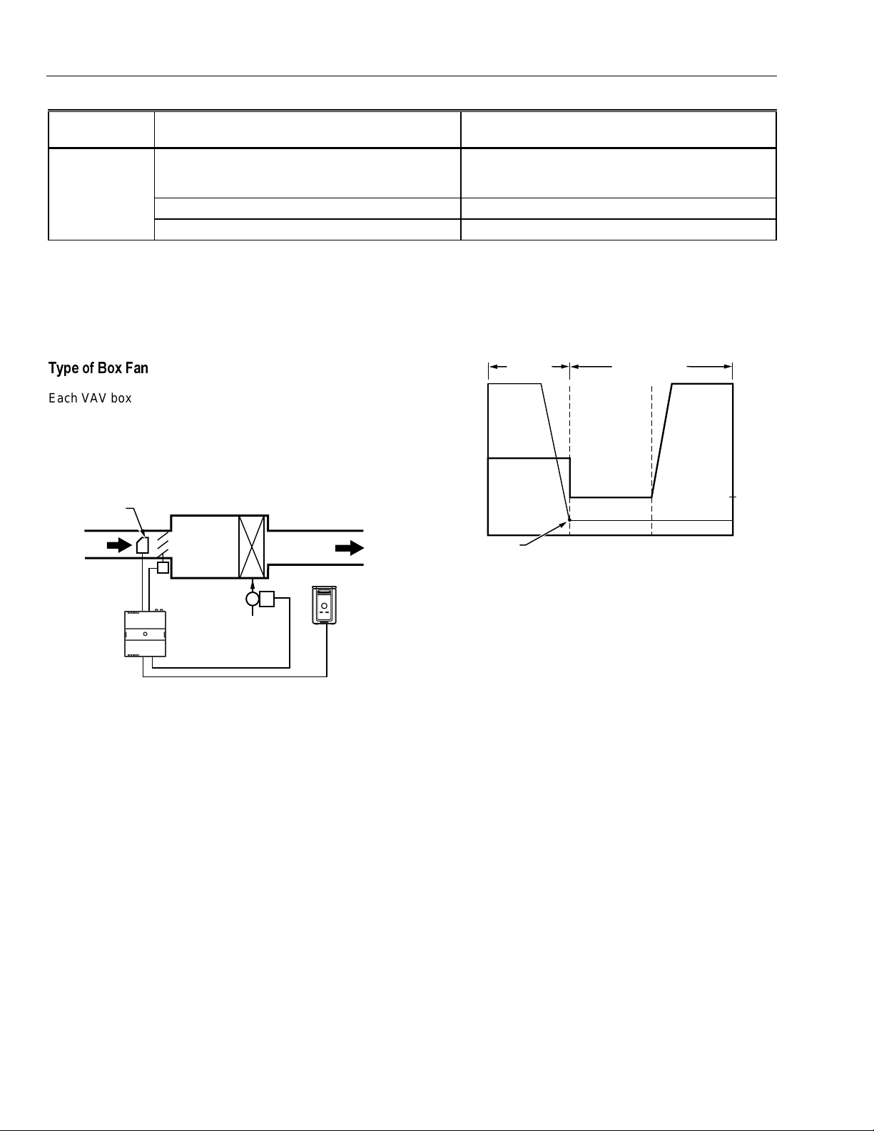
EXCEL 10 W7751B,D,F,H VAVII CONTROLLERS
Table 5. Configuration Options Summary For W7751 Controllers (Continued).
Option
Air
Temperature
Sensor
* If both Reheat and peripheral heat are used in the same application:
Both must be same output type such that both are: staged, floating or PWM
The first and second stage ordering is selectable between stage 1 - reheat, stage 2 peripheral or stage 1- peripheral,
stage 2 reheat.
** Only 1 Analog input is configurable on the W7751H and only if the T7770A or D (no Space temperature setpoint) Wall
modules are used.
Possible Configurations for the W7751B,D,F
Models Possible Configurations for the W7751H Model
1. Discharge Air Temperature 1. Discharge Air Temperature**
2. Supply Air Temperature 2. Supply Air Temperature**
3. None 3. None
7\SH RI %R[ )DQ
Each VAV box that is controlled by a W7751B,D,F,H can
have a series fan (see Fig. 22), a parallel fan (see Fig. 23),
or no fan (see Fig. 12).
The air temperature sensor cannot be used on the
W7751H Smart VAV Actuator with wall modules that have
a setpoint.
AIR FLOW
SENSOR
PRIMARY
AIR
DAMPER
ACTUATOR
W7751
CONTROLLER
Fig. 12. VAV box (without fan).
Figs. 13 through 21 illustrate the W7751B,D,F,H VAV
Controllers that have a box type of (single duct) with
DestHvacMode in (the default of Auto).
Refer to Fig. 13 to see VAV box modes for
Pressure_Independent or (Pressure_Dependent), Reheat
type Float_Reheat/Float_Periph, Non-Proportional.
REHEAT
COIL (OPTIONAL)
DISCHARGE
AIR
VALVE
T7770
M11824
100
PERCENT
OPEN
REHEAT
FLOW
Periph Min Pos
REHEAT
MODE
HeatOccSpt
COOLING MODE
CoolOccSpt
MAX
FLOW
(POS)
MIN
FLOW
(POS)
M11826
Fig. 13. VAV box modes for Reheat Type
Float_Reheat/Float_Periph, Non-Proportional. (suited
for Peripheral heat control because the Peripheral
output closes to a minimum position (Periph Min Pos)
at HeatOccSpt).
Refer to Fig. 14 to see VAV box modes for
Pressure_Independent or (Pressure_Dependent), Reheat
type Float_Reheat/Float_Periph, Proportional.
Pressure Type:
Pressure Independent or (Pressure_Dependent)
Reheat Type:
Float_Reheat or Float_Periph
Proportional Reheat Flow:
Enable
Pressure Type:
Pressure Independent or (Pressure_Dependent)
Reheat Type:
Float_Reheat or Float_Periph
Proportional Reheat Flow:
Disable
Periph Min Pos:
Greater than 0%
74-2949–1 26
Periph Min Pos:
Equals 0
Page 27
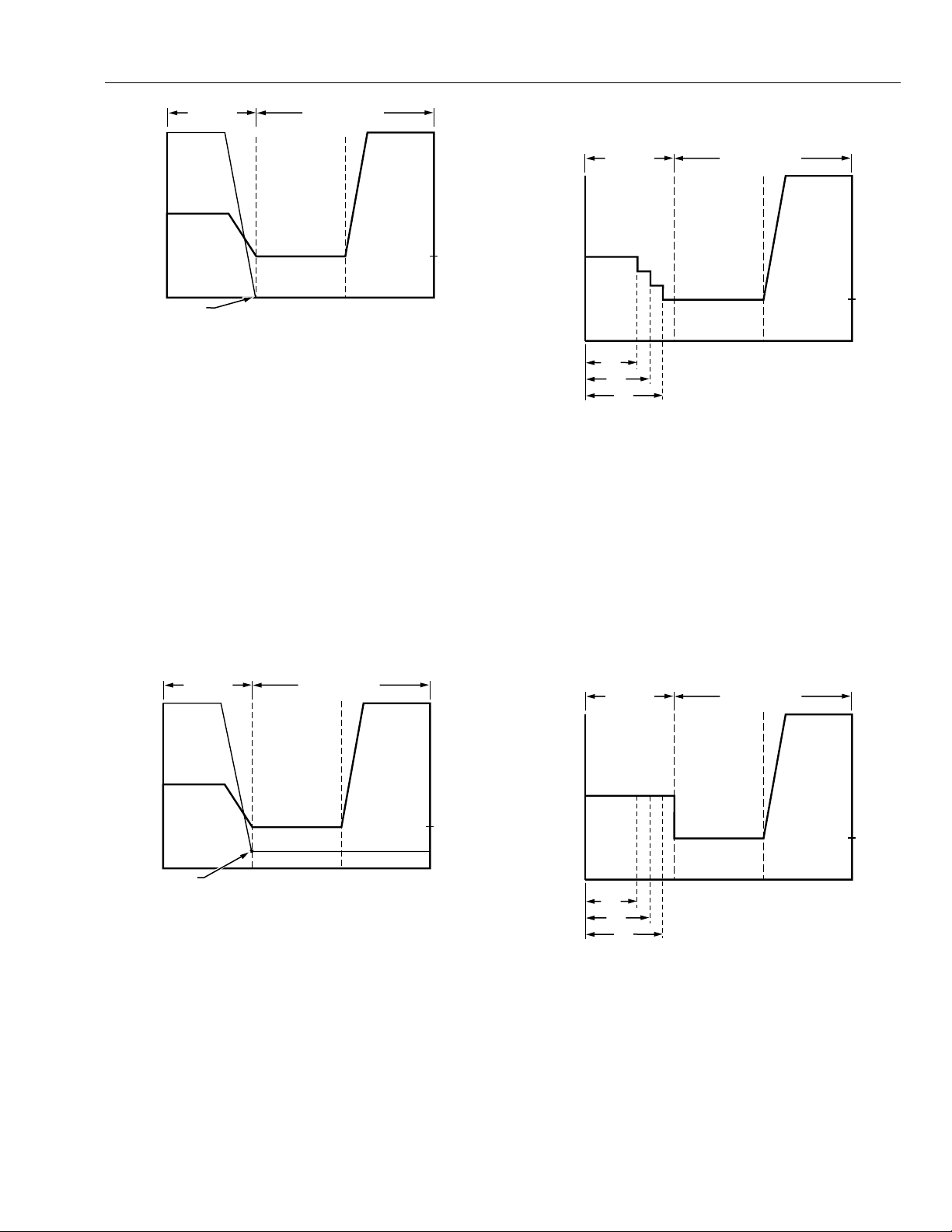
REHEAT
FLOW
MAX
(POS)
MIN
(POS)
M11827
100
PERCENT
OPEN
HeatOccSpt
CoolOccSpt
Periph Min Pos
REHEAT
MODE
COOLING MODE
Fig. 14. VAV box modes for Reheat Type
REHEAT
FLOW
M11828
100
PERCENT
OPEN
HeatOccSpt CoolOccSpt
REHEAT
MODE
COOLING MODE
MAX
FLOW
(POS)
MIN
FLOW
(POS)
Periph Min Pos
REHEAT
FLOW
M11829
ON
ON
ON
STAGE 3
STAGE 2
STAGE 1
HeatOccSpt CoolOccSpt
MAX
FLOW
(POS)
MIN
FLOW
(POS)
REHEAT
MODE
COOLING MODE
Float_Reheat/Float_Periph, Proportional. (suited for
Reheat control because the Reheat closes to zero
percent at HeatOccSpt).
EXCEL 10 W7751B,D,F,H VAVII CONTROLLERS
Proportional Reheat Flow:
Enable
Refer to Fig. 15 to see VAV box modes for
Pressure_Independent or (Pressure_Dependent),Reheat
type Float_Reheat/Float_Periph, Proportional.
Pressure Type:
Pressure Independent or (Pressure_Dependent)
Reheat Type:
Float_Reheat or Float_Periph
Proportional Reheat Flow:
Enable
Periph Min Pos:
Greater than 0%
Fig. 16. VAV box modes for Reheat Type
Elec_ThreeStage - Proportional.
Refer to Fig. 17 to see VAV box modes for Reheat type
Elec_ThreeStage - Non-Proportional.
Pressure Type:
Pressure Independent or (Pressure_Dependent)
Reheat Type:
Elec_ThreeStage or (Elec_ThreeStageBin),
(Elec_OneStage), (Elec_TwoStage)
Proportional Reheat Flow:
Disable
REHEAT
FLOW
REHEAT
MODE
COOLING MODE
MAX
FLOW
(POS)
MIN
FLOW
(POS)
Fig. 15. VAV box modes for Reheat Type
Float_Reheat/Float_Periph, Proportional. (suited for
Peripheral heat control because the Peripheral output
closes to a minimum position (Periph Min Pos) at
HeatOccSpt).
Refer to Fig. 16 to see VAV box modes for Reheat type
Elec_ThreeStage - Proportional.
Pressure Type:
Pressure Independent or (Pressure_Dependent)
Reheat Type:
Elec_ThreeStage or (Elec_ThreeStageBin),
(Elec_OneStage), (Elec_TwoStage)
STAGE 3
STAGE 2
STAGE 1
ON
ON
ON
HeatOccSpt CoolOccSpt
Fig. 17. VAV box modes for Reheat Type
Refer to Fig. 18 to see VAV box modes for Reheat type
Elec_ThreeStage - Non-Proportional.
PeriphThenReheat - Proportional.
Pressure Type:
Pressure Independent or (Pressure_Dependent)
Reheat Type:
Float_Periph_Reheat or (PWM_Periph_Reheat)
27 74-2949–1
M11830
Page 28
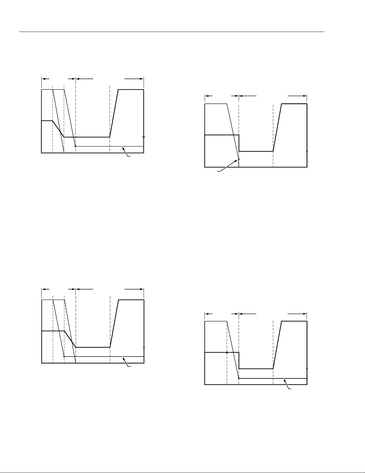
EXCEL 10 W7751B,D,F,H VAVII CONTROLLERS
REHEAT
FLOW
MIN
FLOW
M11831
PERIPHERAL
HTG
REHEAT
HeatOccSpt CoolOccSpt
100
PERCENT
OPEN
REHEAT
MODE
COOLING MODE
MAX
FLOW
(POS)
MIN
FLOW
(POS)
Periph Min Pos
REHEAT
FLOW
MIN
FLOW
M11832
PERIPHERAL
HTG
REHEAT
100
PERCENT
OPEN
REHEAT
MODE
COOLING MODE
HeatOccSpt CoolOccSpt
Periph Min Pos
MAX
FLOW
(POS)
MIN
FLOW
(POS)
100
PERCENT
OPEN
REHEAT
FLOW
MAX
FLOW
MIN
FLOW
M11825
HeatOccSpt CoolOccSpt
REHEAT
MODE
COOLING MODE
Periph Min Pos
Proportional Reheat Flow:
Enable
Periph Min Pos:
0% or greater
Fig. 18. VAV box modes for Reheat type Peripheral
Heating Then Reheat - Proportional
(Float_Periph_Reheat/PWM_Periph_Reheatl).
Refer to Fig. 19 to see VAV box modes for Reheat type
ReheatThenPeriph - Proportional.
Reheat Type:
FloatHotDuctPrDep
Proportional Reheat Flow:
Disable
Periph Min Pos:
0% or greater
Fig. 20. VAV box modes for Reheat Type
Float_Reheat/Float_Periph, no minimum position,
reheat goes to zero percent in cooling mode Non-
proportional (suited for Reheat control because the
Reheat closes to zero percent at HeatOccSpt).
Pressure Type:
Pressure Independent or (Pressure_Dependent)
Reheat Type:
Float_Reheat_Periph or (PWM_Reheat_Periph)
Proportional Reheat Flow:
Enable
Periph Min Pos:
0% or greater
Fig. 19. VAV box modes for Reheat Type Reheat Then
Peripheral Heating Proportional
(Float_Reheat_Periph/PWM_Reheat_Periph).
Refer to Fig. 20 to see VAV box modes for
Press_Dependent, Reheat type
Float_Reheat/FloatHotDuctPrDep, Non-Proportional.
Refer to Fig. 21 to see VAV box modes for Pressure
Dependent, Reheat type Float_Reheat/Float_Periph.
Pressure Type:
Pressure_Dependent
Reheat Type:
Float_Reheat/Float_Periph
Proportional Reheat Flow:
Disable
Periph Min Pos:
0% or greater
100
PERCENT
OPEN
REHEAT
POS.
(DAMPER)
MIN
POS.
M11833
Fig. 21. VAV box modes for Pressure Dependent,
REHEAT
MODE
HeatOccSpt CoolOccSpt
Reheat Type Float Reheat/Float_Periph.
COOLING MODE
Periph Min Pos
MAX
FLOW
(POS)
MIN
FLOW
(POS)
Pressure Type:
Pressure_Dependent
74-2949–1 28
Page 29
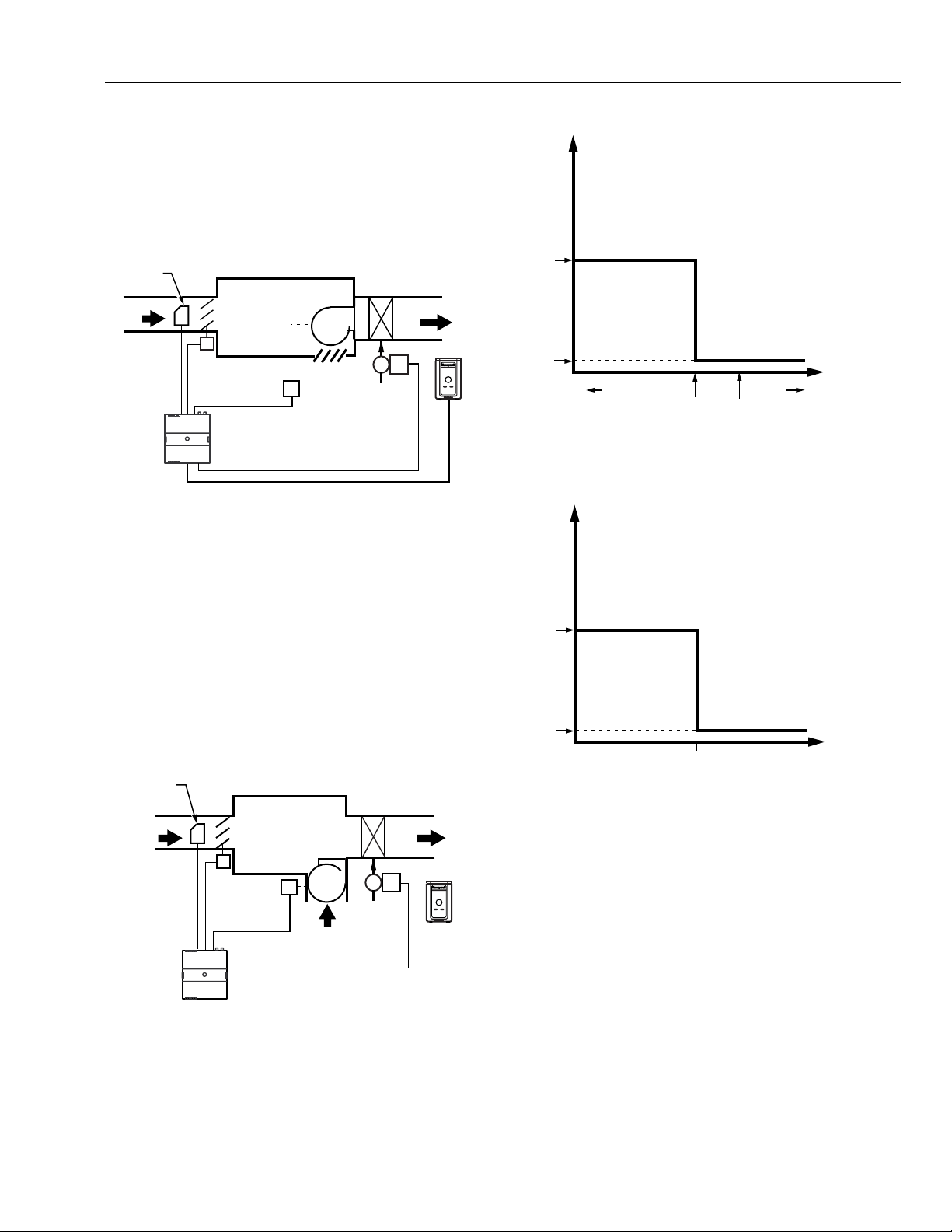
EXCEL 10 W7751B,D,F,H VAVII CONTROLLERS
A Series fan is intended to run continuously when the main
air handler is on and is in-line with the primary air flow
through the box. This configuration is sometimes referred
to as Variable Volume Supply with Constant Volume
Discharge (VVS/CVD).
NOTE: The location of the heating coils can be in the
discharge, as shown in Fig. 22, or in the plenum
return.
AIR FLOW
SENSOR
PRIMARY
AIR
DAMPER
ACTUATOR
W7751
CONTROLLER
FAN
RELAY
OPEN TO
PLENUM
FAN
REHEAT
COIL (OPTIONAL)
DISCHARGE
AIR
VALVE
M11834
T7770
Fig. 22. Series VAV box fan.
PARALLEL FAN TEMP OPERATION:
COOL/REHEAT MODES
ON
OFF
COLD WARM
HeatOccSpt CoolOccSpt
Fig. 24a. Parallel fan temperature operation: for
Cool/Reheat modes.
PARALLEL FAN FLOW OPERATION:
COOL/REHEAT MODES
ROOM
TEMPERATURE
M11836
A parallel fan, see Fig. 23, is not located in the primary air
stream, but is designed to add return air from the plenum
into the air stream delivered to the space. The Excel 10
VAV Controller turns on the parallel fan when the space
temperature falls below Setpoint as a first stage of reheat
(Parallel Temp), or if the air flow falls below a minimum air
flow setpoint to maintain a minimum air flow to the space
(Parallel Flow).
NOTE: The location of the heating coils can be in the
discharge, as shown in Fig. 23, or as part of the
plenum air return, either before or after the fan.
AIR FLOW
SENSOR
PRIMARY
AIR
W7751
CONTROLLER
DAMPER
ACTUATOR
FAN
RELAY
FAN
RETURN AIR
FROM PLENUM
REHEAT
COIL
VALVE
DISCHARGE
AIR
T7770
M11835
ON
OFF
FanEnableFlow
SUPPLY FLOW
M11879
Fig. 24b. Parallel fan flow operation: for Cool/Reheat
modes.
Refer to Fig. 25 to see Dual Duct, Pressure Independent,
with flow mixing that has cold and hot duct flow pickups.
Fig. 23. Parallel VAV box fan.
See Fig. 24a and 24b to see the Heat/Cool Modes for
Parallel Temperature/Flow VAV box fans.
29 74-2949–1
Page 30
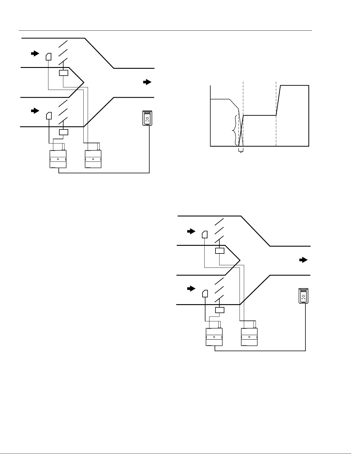
EXCEL 10 W7751B,D,F,H VAVII CONTROLLERS
HOT
DUCT
SUPPLY
AIR
COLD
DUCT
SUPPLY
AIR
FLOW
SENSOR
FLOW
SENSOR
W7751
CONTROLLER
MASTER
M11837
W7751
CONTROLLER
SATELLITE
DISCHARGE
AIR
T7770
SPACE
AIR
TEMP
Fig. 25. Dual Duct, Pressure Independent, with flow
mixing that has cold and hot duct flow pickups (uses a
satellite Excel 10 for hot duct).
Dual Duct Flow Mixing: (For setup and Calibration
refer to the Dual Duct Calibration procedure in
Appendix B.)
Master flow configuration:
Master_Flow_Mix
is set to zero. Since during the initial heating load, both the
hot and cold duct are supplying air, we have flow mixing.
See Fig. 26 for Heat/Cool Modes for Dual Duct, Pressure
Independent, with flow mixing, that has cold and hot duct
flow pickups.
COLD DUCT
MAX CLG FLOW SP
MAX HTG FLOW SP
MIN HTG FLOW SP
MIN CLG FLOW SP
M11838
HOT DUCT
SATELLITE
MIXING
ZONE
COLD HOT
HeatOccSpt
(THIS IS THE
MIXING ZONE)
MASTER
CoolOccSpt
Fig. 26. Heat/Cool Modes for Dual Duct, Pressure
Independent, with flow mixing, that has cold and hot
duct flow pickups.
See Fig. 27 for Dual Duct, Pressure Independent, without
flow mixing, that has cold and hot duct flow pickups.
HOT
DUCT
SUPPLY
AIR
FLOW
SENSOR
Master reheat configuration:
DualDuctReheat
Satellite flow configuration:
Satel_Flow_Mix
Satellite reheat configuration:
DualDuctReheat
NOTE: SrcMaster from the Master Excel 10 must be
bound to DestSatellite of the Satellite Excel 10
and SrcBoxFlow of the Satellite Excel 10 must be
bound to DestFlowTrack of the Master Excel 10
(see Refer Excel 10 Points in Network menu in EVision) in order for this application to function
properly.
Dual duct flow mixing uses two control devices, a master
(for the cold duct) and a satellite (for the hot duct) to
provide pressure independent control. If there is a need for
cooling, dual duct flow mixing will control temperature to
the cooling setpoint, setting the flow control setpoint for the
cold duct between min flow and max flow while setting the
hot duct flow setpoint to zero. If the temperature of the
space is between the cooling and the heating setpoints,
the cold duct will control to the min flow while the hot duct
flow is set to zero. If there is a need for heating, the
controllers will try to control to the heating setpoint by first
modulating the cold duct flow from min flow to zero while
simultaneously modulating the hot duct flow from zero to
min flow. If there is additional need for heat, the hot duct
will modulate from min flow to max flow while the cold duct
DISCHARGE
AIR
COLD
DUCT
SUPPLY
AIR
FLOW
SENSOR
W7751
CONTROLLER
MASTER
M11837
W7751
CONTROLLER
SATELLITE
SPACE
AIR
TEMP
T7770
Fig. 27. Dual Duct, Pressure Independent, without flow
mixing, that has cold and hot duct flow pickups (uses
a satellite Excel 10 for hot duct).
Dual Duct No Flow Mixing: (For setup and Calibration
refer to the Dual Duct Calibration procedure in
Appendix B.)
Master flow configuration:
Master_No_Flow_Mix
74-2949–1 30
Page 31

Master reheat configuration:
DualDuctReheat
Satellite flow configuration:
Satel_No_Flow_Mix
EXCEL 10 W7751B,D,F,H VAVII CONTROLLERS
HOT
DUCT
SUPPLY
AIR
Satellite reheat configuration:
DualDuctReheat
NOTE: SrcMaster from the Master Excel 10 must be
bound to DestSatellite of the Satellite Excel 10
and SrcBoxFlow of the Satellite Excel 10 must be
bound to DestFlowTrack of the Master Excel 10
(see Refer Excel 10 Points in Network menu in EVision) in order for this application to function
properly.
Dual duct flow mixing uses two control devices, a master
(for the cold duct) and a satellite (for the hot duct) to
provide pressure independent control. If there is a need for
cooling, dual duct flow mixing will control temperature to
the cooling setpoint, setting the flow control setpoint for the
cold duct between min flow and max flow while setting the
hot duct flow setpoint to zero. If the temperature of the
space is between the cooling and the heating setpoints,
the cold duct will control to the min flow while the hot duct
flow is set to zero. If there is a need for heating, the
controllers will try to control to the heating setpoint by first
setting the cold duct flow to zero then modulating the hot
duct flow from min flow to max flow; During the heating
and cooling only one damper is being used at any one
time to provide heating or cooling, this provides no flow
mixing.
See Fig. 28 for Heat/Cool Modes for Dual Duct, Pressure
Independent, without flow mixing that has cold and hot
duct flow pickups.
(FLOW SETPOINTS)
MAX COOL
MAX HEAT
MIN COOL
REHEAT
HOT DUCT
SATELLITE
COOL
COLD DUCT
MASTER
COLD
DUCT
SUPPLY
AIR
W7751
CONTROLLER
M11840
FLOAT
REHEAT
FLOW
SENSOR
FLOAT
DAMPER
DISCHARGE
AIR
T7770
SPACE
AIR
TEMP
Fig. 29. Dual Duct, Pressure Independent cooling,
Pressure Dependent heating with flow mixing that has
cold duct flow pickup.
See Fig. 30 for Heat/Cool Modes for (Reheat = Float
Reheat) Dual Duct, Pressure Independent cooling and
Pressure Dependent heating, with flow mixing that has
cold duct flow pickup.
100
PERCENT
POS.
REHEAT MIN FLOW
REHEAT = FLOAT REHEAT
COLD DUCT
MAX
REHEAT FLOW
MIN
MIN HEAT
M11839
COLD HOT
HeatOccSpt CoolOccSpt
Fig. 28. Heat/Cool Modes for Dual Duct, Pressure
Independent, without flow mixing that has cold and
hot duct flow pickups.
See Fig. 29 for Dual Duct, Pressure Independent cooling,
Pressure Dependent heating with flow mixing that has cold
duct flow pickup.
PeriphPos
M11841
COLD HOT
HeatOccSpt CoolOccSpt
Fig. 30. Heat/Cool Modes for (Reheat = Float_Reheat)
Dual Duct, Pressure Independent cooling and Pressure
Dependent heating, with flow mixing that has cold
duct flow pickup.
Dual Duct Flow Mix: (Pressure independent cooling,
pressure dependent heating using one Excel 10.)
Flow configuration:
DD_CDFlowSensor
Reheat configuration:
Float_Reheat
31 74-2949–1
Page 32

EXCEL 10 W7751B,D,F,H VAVII CONTROLLERS
Dual duct flow mixing uses one control device to provide
pressure independent control of the cold duct. The
Floating Reheat, which is traditionally wired to a heating
valve actuator, is wired to a hot duct damper instead.
PeriphPos is used to set the minimum hot duct damper
position, which applies during both reheat and cooling
modes. Flow mixing is achieved by mixing hot duct and
cold duct air, which takes place during the cooling mode
when minimum hot duct position is not zero (PeriphPos),
or during the reheat mode if the cold duct Reheat Flow
value is not zero.
See Fig. 31 for Heat/Cool Modes for (Reheat = Float Hot
Duct Pressure Dependent) Dual Duct, Pressure
Independent cooling and Pressure Dependent heating,
with flow mixing that has cold duct flow pickup.
100
PERCENT
POS.
REHEAT MIN FLOW
PeriphPos
REHEAT = FLOAT REHEAT
COLD DUCT
MAX
REHEAT FLOW
MIN
HOT
DUCT
SUPPLY
AIR
COLD
DUCT
SUPPLY
AIR
FLOW
SENSOR
FLOW
SENSOR
W7751
CONTROLLER
MASTER
M11837
W7751
CONTROLLER
SATELLITE
DISCHARGE
AIR
T7770
SPACE
AIR
TEMP
Fig. 32. Dual Duct, Pressure Independent cooling and
heating, constant volume with hot and cold duct flow
pickups.
M11841
COLD HOT
HeatOccSpt CoolOccSpt
Fig. 31. Heat/Cool Modes for (Reheat =
FloatHotDuctPrDep) Dual Duct, Pressure Independent
cooling and Pressure Dependent heating, with flow
mixing that has cold duct flow pickup.
Dual Duct Flow Mix: (Alternate Configuration)
Flow configuration:
DD_CDFlowSensor
Reheat configuration:
FloatHotDuctPrDep
This configuration is the same as the previous description,
however, setting PeriphPos to a minimum hot duct position
that only applies during reheat mode. During cooling
mode, the hot duct damper goes to zero, thus conserving
energy. Flow mixing is achieved by mixing hot duct and
cold duct air during the reheat mode when the cold duct
Reheat Flow value is not zero.
See Fig. 32 for Dual Duct, Pressure Independent cooling
and heating, constant volume with hot and cold duct flow
pickups.
Dual Duct Constant Volume: (For setup and
Calibration refer to the Dual Duct Calibration
procedure in Appendix B.)
Master flow configuration:
Master_Const_Flow
Master reheat configuration:
DualDuctReheat
Satellite flow configuration:
Satel_Const_Flow
Satellite reheat configuration:
DualDuctReheat
NOTE: SrcMaster from the Master Excel 10 must be
bound to DestSatellite of the Satellite Excel 10
and SrcBoxFlow of the Satellite Excel 10 must be
bound to DestFlowTrack of the Master Excel 10
(see Refer Excel 10 Points in Network menu in EVision) in order for this application to function
properly.
Dual duct flow mixing uses two control devices, a master
(for the cold duct) and a satellite (for the hot duct) to
provide pressure independent control. The dual duct
constant volume application tries to control the space to
the cooling setpoint only. During unoccupied, the controller
will try to control the temperature to either the unocc
heating (if the space temperature is less than the unocc
heating setpoint) or unocc cooling setpoint(if the space
temperature is greater than the unocc cooling setpoint).
The controller is always in cooling mode, adjusting the cool
air from min flow to max flow while simultaneously
adjusting the warm air from max flow to min flow.
74-2949–1 32
Page 33

EXCEL 10 W7751B,D,F,H VAVII CONTROLLERS
See Fig. 33 for Heat/Cool Modes for Dual Duct, Pressure
Independent cooling and heating, constant volume with hot
and cold duct flow pickups.
(FLOW SETPOINTS)
MAX COOL
MAX HEAT
MIN COOL
MIN HEAT
M11843
COLD HOT
COOLING MODE
COLD FLOW
CoolOccSpt
Fig. 33. Heat/Cool Modes for Dual Duct, Pressure
Independent cooling and heating, constant volume
with hot and cold duct flow pickups.
See Fig. 34 for Dual Duct, Pressure Dependent cooling
and heating, with Flow mixing and no flow pickups.
HOT
DUCT
SUPPLY
AIR
COLD
DUCT
SUPPLY
AIR
W7751
CONTROLLER
FLOAT
REHEAT
FLOAT
DAMPER
DISCHARGE
AIR
T7770
SPACE
AIR
TEMP
HOT DUCT
100
PERCENT
POS.
Periph Min Pos
M11845
REHEAT FLOW
COLD HOT
HeatOccSpt CoolOccSpt
COLD DUCT
MAX POS.
MIN POS.
Fig. 35. Heat/Cool Modes for (Reheat = Float Reheat)
Dual Duct, Pressure Dependent cooling and heating,
with flow mixing with no flow pickups.
Dual Duct Press Flow Mix: (Pressure dependent
cooling and heating using one Excel 10.)
Flow configuration:
DD_NoFlowSensor
Reheat configuration:
Float_Reheat
Dual duct flow mixing uses one control device to provide
pressure dependent control of the cold and hot ducts. The
Floating Reheat, which is traditionally wired to a heating
valve actuator, is wired to a hot duct damper instead.
PeriphPos is used to set the minimum hot duct damper
position, which applies during both reheat and cooling
modes. Flow mixing is achieved by mixing hot duct and
cold duct air, this takes place during the cooling mode
when minimum hot duct position is not zero, or during the
reheat mode if the cold duct Reheat Flow value is not zero.
See Fig. 36 for Heat/Cool Modes for Dual Duct, Pressure
Dependent cooling and heating, with Flow mixing and no
flow pickups.
REHEAT = FloatHotDuctPrDep
HOT DUCT
100
PERCENT
OPEN
COLD DUCT
MAX POS.
M11844
NO FLOW PICKUPS
Fig. 34. Dual Duct, Pressure Dependent cooling and
heating, with Flow mixing and no flow pickups.
See Fig. 35 for Heat/Cool Modes for (Reheat = Float
Reheat) Dual Duct, Pressure Dependent cooling and
heating, with flow mixing that has cold duct flow pickup.
PeriphPos
MIN POS.
REHEAT MIN POS
M11846
COLD HOT
HeatOccSpt CoolOccSpt
Fig. 36. Heat/Cool Modes for Dual Duct, Pressure
Dependent cooling and heating, with Flow mixing and
no flow pickups.
33 74-2949–1
Page 34

EXCEL 10 W7751B,D,F,H VAVII CONTROLLERS
Dual Duct Press Flow Mix: (Alternate Configuration)
Flow configuration:
DD_NoFlowSensor
Reheat configuration:
FloatHotDuctPrDep
This configuration is the same as the previous description,
however, setting PeriphPos to a minimum hot duct position
that only applies during reheat mode. During cooling
mode, the hot duct damper goes to zero, thus conserving
energy. Flow mixing is achieved by mixing hot duct and
cold duct air during the reheat mode when the cold duct
Reheat Flow value is not zero.
See Fig. 37 for Dual Duct, Pressure Independent
discharge, with Constant Volume and Discharge air flow
pickup.
HOT
DUCT
SUPPLY
AIR
FLOAT
REHEAT
FLOW
SENSOR
DISCHARGE
AIR
high with a small heating flow capacity will not let the cold
damper go to zero during a high demand for heat.)
See Fig. 38 for Heat/Cool Modes for Dual Duct, Pressure
Independent Cooling and Pressure Dependent Heating,
with Constant Volume and Discharge air flow pickup.
MAX. FLOW CONTROLS
COLD FLOW
HOT DUCT
100
PERCENT
POS.
TEMP CONTROLS HOT
DAMPER POSITION
COLD HOT
HeatOccSpt CoolOccSpt
COLD DUCT
MAX
FLOW
(TOTAL
FLOW)
Periph Min Pos
M11848
Fig. 38. Heat/Cool Modes for Dual Duct, Pressure
Independent Cooling and Pressure Dependent
Heating, with Constant Volume and Discharge air flow
pickup.
See Fig. 39 for Dual Duct, Pressure Dependent cooling
and heating, with no Flow mixing and no flow pickups.
COLD
DUCT
SUPPLY
AIR
W7751
CONTROLLER
M11847
FLOAT
DAMPER
SPACE
AIR
TEMP
T7770
Fig. 37. Dual Duct, Pressure Independent discharge,
with Constant Volume and Discharge air flow pickup.
Dual Duct Discharge Sensor Constant Volume
(pressure independent discharge using one Excel 10).
Flow configuration:
DD_DAFlowSenConst
Reheat configuration:
Float_Reheat
Dual duct flow mixing uses one control device to provide
pressure independent control of the cold duct and total
discharge air. In this control sequence, the temperature
sensor controls the Hot duct damper position from the
PeriphPos minimum hot duct position to the 100 percent
position. The discharge flow sensor, which picks up the
cumulative flow of both the cold and hot duct air flows, is
used to determine the total flow of air. This total flow of air
is used to control the cold duct damper, using whatever
amount of cold air is necessary to maintain a single flow
value of MaxFlow. (Be aware that setting the Max flow too
HOT
DUCT
SUPPLY
AIR
COLD
DUCT
SUPPLY
AIR
W7751
CONTROLLER
M11844
FLOAT
REHEAT
FLOAT
DAMPER
NO FLOW PICKUPS
DISCHARGE
AIR
SPACE
AIR
TEMP
Fig. 39. Dual Duct, Pressure Dependent cooling and
heating, with no Flow mixing and no flow pickups.
Dual Duct Press Flow Mix (pressure dependent
cooling and heating using one Excel 10).
Flow configuration:
DD_NoFlowSensor
Reheat configuration:
FloatHotDuctPrDep
T7770
74-2949–1 34
Page 35

EXCEL 10 W7751B,D,F,H VAVII CONTROLLERS
Dual duct flow mixing uses one control device to provide
pressure dependent control of the cold and hot ducts. The
Floating Reheat, which is traditionally wired to a heating
valve actuator, is wired to a hot duct damper instead.
PeriphPos will be set to a minimum hot duct position that
only applies during reheat mode. During cooling mode, the
hot duct damper goes to zero, thus conserving energy.
Flow mixing is avoided by setting the cold duct Reheat
Flow Value to zero. The minimum flow value to the space
will be the minimum hot duct damper position during
reheat mode or the cold duct min position during cooling.
See Fig. 40 for Heat/Cool Modes for Dual Duct, Pressure
Dependent cooling and heating, with no Flow mixing and
no flow pickups.
HOT DUCT
100
PERCENT
POS.
Periph Min Pos
COLD
REHEAT
POS. =
ZERO
PERCENT
M11849
COLD HOT
HeatOccSpt CoolOccSpt
COLD DUCT
MAX DAMPER
POS.
MIN DAMPER
POS.
Dual Duct Pressure Independent (pressure
independent heating and cooling using one Excel 10).
Flow configuration:
DD_DAFlowSensor.
Reheat configuration:
Float_Reheat
Dual duct flow mixing uses one control device to provide
pressure independent control of the cold and hot ducts.
The Floating Reheat, which is traditionally wired to a
heating valve actuator, is wired to a hot duct damper
instead. During reheat mode, only the hot duct damper is
controlled and the cold duct is closed. During the cooling
mode, only the cold duct damper is controlled, and the hot
duct is closed.
See Fig. 42 for Heat/Cool Modes for Dual Duct, Pressure
Independent Heating and Cooling, with Discharge air flow
pickup.
MAX
FLOW
REHEAT
MODE
COOLING MODE
MAX
COLD DUCTHOT DUCT
FLOW
Fig. 40. Heat/Cool Modes for Dual Duct, Pressure
Dependent cooling and heating, with no Flow mixing
and no flow pickups.
See Fig. 41 for Dual Duct, Pressure Independent Heating
and Cooling, with Discharge air flow pickup.
HOT
DUCT
SUPPLY
AIR
COLD
DUCT
SUPPLY
AIR
W7751
CONTROLLER
FLOAT
REHEAT
FLOAT
DAMPER
FLOW
SENSOR
DISCHARGE
AIR
T7770
SPACE
AIR
TEMP
MIN
FLOW
COLD HOT
HeatOccSpt CoolOccSpt
M11850
Fig. 42. Heat/Cool Modes for Dual Duct, Pressure
Independent Heating and Cooling, with Discharge air
flow pickup.
See Fig. 43 for Single Duct, Pressure Independent
Cooling, with PWM Parallel Fan.
PARALLEL
FAN
RETURN AIR
FLOW
SENSOR
SUPPLY AIR
55 DEGREES F
M11851
FROM PLENUM
FLOAT
DAMPER
W7751
CONTROLLER
DISCHARGE
AIR
SPACE
AIR
TEMP
T7770
M11847
Fig. 41. Dual Duct, Pressure Independent Heating and
Cooling, with Discharge air flow pickup.
Fig. 43. Single Duct, Pressure Independent Cooling,
with PWM Parallel Fan.
35 74-2949–1
Page 36

EXCEL 10 W7751B,D,F,H VAVII CONTROLLERS
PWM fan.
Use this only with single duct configurations. The PWM fan
is a variable fan that controls the amount of return air or
return plenum air to the space. The PWM fan acts in
opposite to the cooling duct damper position for pressure
dependent operation, or in opposite to the cooling duct
flow for pressure independent.
See Fig. 44 for Modes for Single Duct, Pressure
Independent Cooling, with Parallel Fan.
See Fig. 45 for Exhaust Tracking Flow Control.
COLD
DUCT
SUPPLY
AIR
nvoFLOW
TRACK
FLOW
SENSOR
DISCHARGE
AIR
W7751
CONTROLLER
NUMBER1
MAX
FLOW
MIN
FLOW
COLD
PWM FAN 100 PERCENT
HeatOccSpt CoolOccSpt
COLD DUCT
Fig. 44. Modes for Single Duct, Pressure Independent
Cooling, with Parallel Fan.
T7770
SPACE
AIR
TEMP
HOT
MAX
FLOW
MIN
FLOW
M12800
nviFLOW
TRACK
nvoFLOW
TRACK
nviFLOW
TRACK
FLOW
SENSOR
FLOW
SENSOR
nvoFLOW
TRACK
DISCHARGE
AIR
W7751
CONTROLLER
NUMBER1
DISCHARGE
AIR
W7751
CONTROLLER
NUMBER1
T7770
T7770
SPACE
AIR
TEMP
SPACE
AIR
TEMP
FLOW
SENSOR
nviFLOW
TRACK
EXHAUST
AIR
W7751
CONTROLLER
NUMBER1
M12801
Configuration of Box Type, Flow Type
Box Type Flow Type
Excel 10 VAV number 1 =Single_Duct SD_Normal_Flow
Excel 10 VAV number 2 =Single_Duct SD_Normal_Flow
Excel 10 VAV number 3 = Single_Duct SD_Normal_Flow
Excel 10 VAV number 4 = Flow_Tracking FLOW_Tracking
Bind the SrcFlowTrack of controller number 1 to the DestFlowTrack of number 2, the SrcFlowTrack of number 2 to the
DestFlowTrack of number 3, the SrcFlowTrack of number 3 to the DestFlowTrack of number 4. See Refer Excel 10 Points in
Network menu in E-Vision.
Fig. 45. Exhaust Tracking Flow Control.
See Fig. 46 for Share Wall Module.
74-2949–1 36
Page 37

COLD DUCT
SUPPLY AIR
EXCEL 10 W7751B,D,F,H VAVII CONTROLLERS
SrcMaster
DestSatellite
DestSatellite
FLOW
SENSOR
FLOW
SENSOR
FLOW
SENSOR
DISCHARGE
AIR
W7751
CONTROLLER
NUMBER 1
DISCHARGE
AIR
W7751
CONTROLLER
NUMBER 2
DISCHARGE
AIR
W7751
CONTROLLER
NUMBER 3
T7770
SPACE
AIR
TEMP
DISCHARGE
AIR
RETURN AIR
PLENUM
FLOW
SENSOR
W7751
CONTROLLER
NUMBER 4
DestSatellite
M11865
Flow Type Box Type Wall Module Type
Configuration of VAV Controllers for Share Wall Module.
Excel 10 VAV number 1 = SD_Normal_Flow Single_Duct Sensor_Setpoint
Excel 10 VAV number 2 = Shared_Cntrl Single_Duct No_Sensor
Excel 10 VAV number 3 = Shared_Cntrl Single_Duct No_Sensor
Excel 10 VAV number 4 = Shared_Cntrl Single_Duct No_Sensor
Bind SrcMaster of VAV number 1, as Source controller, (see Refer Excel 10 Points in Network menu in E-Vision) to the
DestSatellite of VAV number 2 through VAV number 4, as the Destination Excel 10’s. Refer to the Share Wall Module under
section on Wall Module Options for additional rules and cautions on using the Share Wall Module option.
NOTE: See Fig. 51 for sharing a T7780 DDWM.
Fig. 46. Share Wall Module.
T7780 DDWM Binding for VAVII Controllers
Source Controller Destination Controller
DDWM SrcRmTemp VAVII DestRmTemp
DDWM SrcRmTempSpt VAVII DestRmTempSpt
DDWM SrcHvacMode VAVII DestHvacMode
DDWM SrcManualOcc VAVII DestManualOcc
VAVII SrcRmTempSpt DDWM DestRmTempActSpt
VAVII SrcUnitStatus DDWM DestUnitStatus
VAVII Configuration
Wall Module Type: No_Sensor
Flow Type: SD_Normal_Flow
Refer to the Binding Guide for T7780 DDWM in E-Vision
Help (Tables 13, 14 ,15) for additional binding information
for binding the T7780 to the VAVII and other Excel 10
Controllers.
37 74-2949–1
Page 38

EXCEL 10 W7751B,D,F,H VAVII CONTROLLERS
7\SHRI5HKHDW&RLO
Each VAV box can contain a coil(s) for reheating the air
delivered to the space. The Excel 10 VAV Controller can
control staged electric heat elements, solenoid valves,
PWM, Series 60 (floating) or pneumatic modulating valves.
NOTE: Pneumatically actuated valves can be controlled
using a floating-to-pneumatic transducer device.
See Application Step 5. Order Equipment, for
further information. Transducer devices are also
available to convert the floating outputs to a
voltage signal.
The staged reheat control algorithm can control one, two,
or three stages of reheat (a third stage of reheat is only
available if configured as three stage binary control on the
W7751H Smart VAV Actuator). In addition to the
proportional, integral, derivative (PID) control algorithm,
the Excel 10 VAV Box Controller has an intelligent
anticipation cycler incorporated into the staged reheat
algorithm. The anticipator control works in unison with the
PID temperature control algorithm and cycles the staged
reheat coil providing space temperature control with the
accuracy of modulating reheat. The stages are activated
through Triac digital outputs, one for each stage, wired to
24 Vac contactors (see Fig. 61, 68 and 73 in Application
Step 4. Prepare Wiring Diagrams). These outputs can also
control 24 Vac solenoid valves on hot water coils instead
of electric heat elements. Fig. 47 depicts a typical VAV box
with staged reheat.
The Series 60 modulating control is provided through two
Triac digital outputs, one to pulse the valve actuator open
and one to pulse it closed. Damper control output Triacs
operate similarly. See Fig. 62, 66, 67, and 72 in
Application Step 4. Prepare Wiring Diagrams for wiring
details that connect Series 60 actuators to Excel 10 VAV
Controllers. Fig. 67 depicts a typical VAV box with
modulating reheat.
PWM control positions the actuator based on the length, in
seconds, of the pulse from the digital output. For PWM,
the controller outputs a pulse whose length consists of two
parts, a minimum and a maximum. The minimum pulse
time represents the analog value of zero percent (also
indicating a signal presence) and the maximum pulse
length that represents an analog value of 100 percent. If
the analog value is greater than zero percent, an additional
time is added to the minimum pulse time. The length of
time added is directly proportional to the magnitude of the
analog value. The PWM actuator will begin to use the
analog value at the end of the pulse and will continue to
use this value until a new pulse is received. Refer to
Appendix B under PWM Control for an example. Series 60
actuators are generally less expensive than those for
PWM, but the trade-off is that PWM requires only a single
controller digital output while floating control uses two
digital outputs.
Fig. 71 depicts a typical VAV box using a PWM Valve
Actuator. See Fig. 64, 70 and 75 for wiring an MMC325
Pneumatic Transducer to a W7751 VAV Controller.
AIR FLOW
SENSOR
PRIMARY
AIR
DAMPER
ACTUATOR
STAGED
REHEAT
COIL
CONTACTORS
W7751
CONTROLLER
DISCHARGE
AIR
M11867
T7770
Fig. 47. VAV box with staged reheat coils.
HOT WATER
AIR FLOW
SENSOR
PRIMARY
AIR
DAMPER
ACTUATOR
W7751
CONTROLLER
OR STEAM
REHEAT COIL
FLOATING
ACTUATOR
VALVE
DISCHARGE
AIR
T7770
M11868
Fig. 48. VAV box with modulating reheat coil (Series 60
floating).
CAUTION
When choosing the pneumatic pressure range,
make sure that the close-off pressure is 2 to 3 psi
greater than that of the spring range. When using a
spring range of 5 to 10 psi with 10 psi as the
do not
Closed position,
transducer;
use
use the 0 to 10 psi
the 0 to 20 psi transducer as the
recommended selection.
Pneumatic Valve Actuator Control
Pneumatic hot water or steam valve actuator control can
be provided through either PWM using one Triac digital
output or by Series 60 using two Triac digital outputs as is
used for the Series 60 electric control. These two outputs
are used to control the transducer interface that converts
to a pneumatic signal.
74-2949–1 38
Page 39
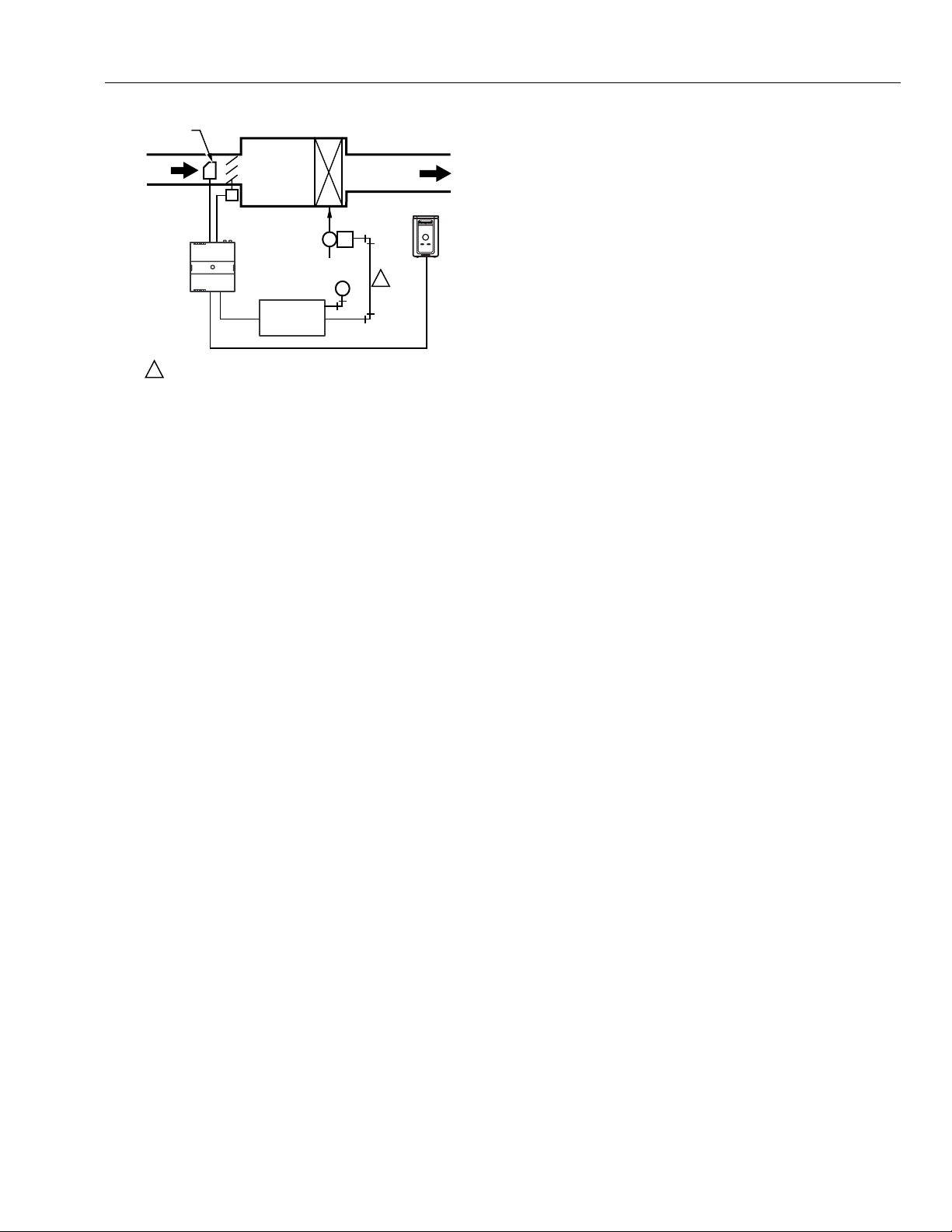
EXCEL 10 W7751B,D,F,H VAVII CONTROLLERS
HOT WATER
VALVE
MMC325
OR STEAM
REHEAT COIL
DISCHARGE
AIR
PNEUMATIC
ACTUATOR
M
PNEUMATIC
TRANSDUCER
T7770
1
M11869
AIR FLOW
SENSOR
PRIMARY
AIR
DAMPER
ACTUATOR
W7751
CONTROLLER
1
PNEUMATIC MAIN OR BRANCH LINE MUST BE 1/4 IN. (6 MM)
OR LARGER TUBING. A MINIMUM OF 6 FT (1.8M) OF TUBING
IS NEEDED IN A BRANCH LINE.
Fig. 49. VAV box with modulating reheat coil
(pneumatic valve actuator).
([KDXVW7UDFNLQJ2SWLRQ
The basic flow control algorithm can be run in either of two
modes: the Temperature Control mode, where the flow
rate is modulated to maintain the space temperature and
the Exhaust Tracking Control mode (refer to Fig. 45),
where the exhaust flow rate is modulated to track the
supply air flow in other controllers. If exhaust tracking is
selected, the air flow removed from the space is based on
the sum of flow rate signals sent over the E-Bus from other
controllers (plus or minus a differential). Use the Exhaust
Tracking Control mode only as required by the job
specifications.
2FFXSDQF\6HQVRU
W7751B, D, F Excel 10 VAV Controllers provide a digital
input for connection to an Occupancy Sensor (W7751H
Smart Actuator requires a Network input for this
application, Refer to Note 2 below). This is a device, such
as a passive infrared motion detector, that contains a dry
contact (see following NOTE) closure to indicate whether
or not people are present in the space. The Excel 10 VAV
Controller expects a contact closure to indicate that the
space is Occupied. See Fig. 60 through 63 and 66 through
69 in Application Step 4. Prepare Wiring Diagrams for
details on wiring connections.
The control algorithm in the Excel 10 VAV Controller uses
the Occupancy Sensor, if configured, to determine the
Effective Occupancy (see Table 2) mode of operation. If
the Time Of Day (TOD) schedule indicates an Occupied
state, and the Occupancy Sensor contact is closed, the
Effective Occupancy mode will be Occupied. However, if
the TOD schedule indicates an Occupied state and the
Occupancy Sensor contact is open, then the Effective
Occupancy mode will be STANDBY. The flow control
algorithm will then control to the STANDBY Cooling and
Heating Setpoints.
If the Occupancy Sensor is not configured, a local
controller can be put in the STANDBY mode only by either
a one-to-one association of the occupancy sensor from
another Excel 10 VAV Controller to the local controller, or
by receiving the STANDBY mode signal via the E-Bus.
NOTES:
1. The Excel 10 VAV Controller has limited power
available (only 9 mA at 4.8 volts) for checking the
digital inputs for contact closures. It is very important
that the device used contains high quality,
noncorroding contacts with resistivity that does not
degrade; that is, increase over time. Use noble metal
(such as gold or silver), pimpled or sealed contacts
to assure consistent, long term operation.
2. The W7751H has no configurable digital inputs. If
the W7751H Smart Actuator requires the Window
open, Occupancy, or Heat/Cool inputs, then it must
be bound over the network (E-Bus) to another
W7751 VAV controller that has those physical digital
inputs.
The recommended devices for use with the Excel 10 VAV
Controller are the EL7628A1007 Ceiling Mount Infrared or
the EL7680A1008 Wall Mounted Wide View Infrared
Occupancy Sensors. If ultrasonic sensors are required, the
EL7611A1003 and the EL7612A1001 Occupancy Sensors
are recommended. An EL76XX Power Supply/Control Unit
is required for use with these occupancy sensors. The
EL7630A1003, can power up to four sensors, and is
multitapped for several line voltages. The EL7621A1002
can power three sensors and connects to 120 Vac line
voltage. The EL7621A1010 can also power three sensors
but connects to 277 Vac line voltage.
:LQGRZ2SHQ&ORVHG'LJLWDO,QSXW
W7751B, D, F Excel 10 VAV Controllers provide a digital
input to detect whether a window in the space was opened
(W7751H Smart Actuator requires a Network input for this
application, Refer to Note 2 below). The Excel 10 VAV
Controller can be connected to a dry contact (see the
following NOTE and Fig. 60 through 63 and 66 through 69
in Application Step 4. Prepare Wiring Diagrams, for
details) or a set of contacts wired in series (for monitoring
multiple windows) to verify that the window(s) are closed.
The algorithm expects a contact closure to indicate the
window is closed. If an open window is detected, the
algorithm changes the mode of operation to CLOSED,
which commands the box damper to the position set in
ZeroDmprPos (typically zero or a low value).
If the Window Sensor is not configured, a W7751B,D,F
and H Controller can be put in the CLOSED mode using
only two methods, either a one-to-one association of the
window sensor from another Excel 10 VAV Controller to
the local controller, or by receiving the CLOSED mode
signal via the E-Bus.
39 74-2949–1
Page 40

EXCEL 10 W7751B,D,F,H VAVII CONTROLLERS
NOTES:
1. (This is the same NOTE as in the Occupancy Sensor
section.) The Excel 10 VAV Controller has limited
power available (only 9 mA at 4.8 volts) for checking
the digital inputs for contact closures. It is very
important that the device used contains high quality,
noncorroding contacts with resistivity that does not
degrade; that is, increase over time. Use noble metal
(such as gold or silver), pimpled or sealed contacts
to assure consistent, long term operation.
2. The W7751H has no configurable digital inputs. If
the W7751H Smart Actuator requires the Window
open, Occupancy, or Heat/Cool inputs, then it must
be bound over the network (E-Bus) to another
W7751 VAV controller that has those physical digital
inputs.
+HDW&RROFKDQJHRYHU
W7751B, D, F Excel 10 VAV Controllers provide a digital
input for connection to an Heat/Cool change over input
(W7751H Smart Actuator requires a Network input for this
application, Refer to Note 2 below). The Excel 10 VAV
Controller expects a contact closure to indicate that the
controller will be put into the heat mode or an open contact
to be put into the cooling mode. See Figs. 30 through 34
and 36 through 40 in Application Step 4. Prepare Wiring
Diagrams for details on wiring connections.
NOTES:
1. (This is the same NOTE as in the Occupancy Sensor
section.) The Excel 10 VAV Controller has limited
power available (only 9 mA at 4.8 volts) for checking
the digital inputs for contact closures. It is very
important that the device used contains high quality,
noncorroding contacts with resistivity that does not
degrade; that is, increase over time. Use noble metal
(such as gold or silver), pimpled or sealed contacts
to assure consistent, long term operation.
2. The W7751H has no configurable digital inputs. If
the W7751H Smart Actuator requires the Window
open, Occupancy, or Heat/Cool inputs, then it must
be bound over the network (E-Bus) to another
W7751 VAV controller that has those physical digital
inputs.
:DOO0RGXOH2SWLRQV
As previously discussed, there are four basic varieties of
T7770 Wall Modules (see Product Names and
Construction sections). Also, a T7770 can be shared
among two or more W7751 Controllers. A T7780 Digital
Display Wall Module (DDWM) can also be used in place of
the T7770, but the T7780 DDWM requires a network node
address which will decrease the number of nodes
available for other Excel 10 controllers. The control
algorithm must be given this wall module information when
configuring the W7751 (see Application Step 6. Configure
Controllers).
Common Temperature Control (Share Wall Module)
When one or more terminal units serve a common area
and a single temperature sensor is specified or is desired
to be used for these boxes, the Share Wall Module option
can be configured (refer to Fig. 45). One Excel 10 VAV
Controller will be configured with a wall module and have
the desired options. The other Excel 10 VAV Controller(s)
will be configured without wall modules. Refer to the CARE
User's Manual, form 74-5587. In order to link these units
together, link Share Wall Module through one-to-one
options in the Network Manager. Use E-Vision Refer Excel
10 Points option to bind the Wall Module information
between the Source (SrcMaster) and Destination
(DestSatellite) controllers. In this particular case, the
Master temperature control algorithm will control both the
Master and Satellite controller outputs.
The preferred method is to use the Share Wall Module
(Shared_Cntrl).
However, an alternative method is to bind the SrcRmTemp
of the controller (Master) that has the wall module
connected to it, to the DestRmTemp in each of the
destination controllers (Satellites) that do not have wall
modules. Each controller would use its own temperature
control algorithm and internal setpoints. This method could
be used when there are many VAV boxes serving the
same zone that have different configurations which do not
allow using the Share Wall Module option.
NOTE: Be aware of a potential problem the (SrcRmTemp
The following
Module option.
and DestRmTemp) method could allow, since
each VAV box is executing its own temperature
control algorithm (there could be some conflicting
control. For example: One box could be cooling at
Max flow and another box could be at Min flow or
even in the reheat mode.
IMPORTANT
items apply to the Share Wall
IMPORTANT
The type of reheat option must be the same in
each unit; for example, all units must be either
staged electric heat or steam/hot water heat.
If the staged heat option is present, the master
unit (with temperature sensor) must have the
same or greater number of stages as any satellite
unit.
Some or all of the satellite units can be
configured without any heat option.
If the Share Wall Module option is used, the
satellite units will not use any Internal
Temperature Setpoints. The master controller
Setpoints, as well as Occupancy and Command
mode status, will be used in each satellite unit.
Each satellite unit will have and use its own MAX,
MIN, and Reheat Flow Setpoints.
Share Wall Module option can also be used when
none of the terminal units have any heating coils.
If any units have terminal fans, the type, either
serial or parallel, must be the same and the
master unit must be configured with a fan.
74-2949–1 40
Page 41

EXCEL 10 W7751B,D,F,H VAVII CONTROLLERS
6HQVRU2SWLRQV
The C7770A, C7031C1031 or C7031C1033 Air
Temperature Sensors are direct-wired temperature
sensors that are used to sense discharge or return air in a
duct controlled by a W7751 Controller.
NOTE: The C7770A, C7031C1031 or C7031C1033 Air
Temperature Sensors cannot be used with the
T7770B,C Wall Modules when controlling any
W7751H Controller.
3QHXPDWLF5HWURILW$SSOLFDWLRQV
For projects with existing pneumatically-actuated reheat
valves, the Excel 10 VAV Controller output must be
converted to a pneumatic signal using a transducer device
developed for use with Excel 10 VAV Controllers. The
transducer is available through Honeywell or directly from
the manufacturer, Mamac Systems (see Table 9 for
ordering information). Be sure to observe the following
CAUTION.
CAUTION
Pneumatic transducers should not be used to
control VAV box dampers; Instead use
ML6161B1000 Motors. Pneumatic transducers are
intended to control only pneumatic reheat valves.
When planning the system layout, consider potential
expansion possibilities to allow for future growth. Planning
is very important when preparing to add HVAC systems
and controllers in future projects.
T7770 Wall Modules can be installed as either hardwired
I/O-only devices or additional wiring can be run to them
(for the E-Bus network ) allowing a CARE/E-Vision
operator terminal to have access to the E-Bus. The
application engineer needs to determine how many wall
modules are required of each kind; that is, how many
T7770s and T7780s are in the system. (All T7780s are
connected to the E-Bus and occupy a node address and
all have a connected network access jack.) How many
T7770s with E-Bus network connections and how many
T7770s without E-Bus network connections are being
installed on the job. Clearly document which T7770 wall
modules (if any) have network access and locations of any
T7780s. This information is required during installation to
ensure that the proper number and type of wires are pulled
to the wall modules, and the building operators are
informed about where they can plug in to the E-Bus
network with a portable operator terminal (see Fig. 50 and
51). Refer to Step 4. Prepare Wiring Diagrams for details,
about the about the wiring differences between the two
types.
EXCEL 10
W7751
VAV
CONTROLLER
APPLICATION STEPS
Overview
The seven application steps shown in Table 6 are planning
considerations for engineering an Excel 10 W7751
System. These steps are guidelines intended to aid
understanding of the product I/O options, bus arrangement
choices, configuration options and the Excel 10 W7751
Controller role in the overall EXCEL 5000 OPEN System
architecture.
Table 6. Application Steps.
Step No. Description
1 Plan The System
2 Determine Other Bus Devices Required
3 Lay Out Communication and Power Wiring
4 Prepare Wiring Diagrams
5 Order Equipment
6 Configure Controllers
7 Troubleshooting
Step 1. Plan The System
Plan the use of the W7751 Controllers according to the job
requirements. Determine the location, functionality and
sensor or actuator usage. Verify the sales estimate of the
number of W7751 Controllers and T7770 and T7780 Wall
Modules required for each model type. Also check the
number and type of output actuators and other required
accessories.
NOTEBOOK PC
SHIELDED
INTERFACE
RS-232
SERIAL
PORT
CABLE
Q7752A
SLTA
CABLE
PART
NO. 205979
E-BUS
PORT
M11870
Fig. 50. Connecting the portable operator terminal to
the E-Bus.
Refer to the E-Bus Wiring Guidelines, form 74-2865 for
complete description of network topology rules. See
Application Step 3. Lay Out Communications and Power
Wiring, for more information on bus wiring layout, and see
Figs. 60 through 74 in Application Step 4. Prepare Wiring
Diagrams, for wiring details.
The application engineer must review the Direct Digital
Control (DDC) job requirements. This includes the
Sequences of Operation for the W7751 VAV units, and for
the system as a whole. Usually there are variables that
must be passed between the W7751 VAV Controllers and
other zone controller(s), or central plant controller(s) that
are required for optimum system-wide operation. Typical
examples are the TOD Occ/Unocc signal, the outdoor air
temperature, demand limit control signal, and smoke
control mode signal.
41 74-2949–1
Page 42

EXCEL 10 W7751B,D,F,H VAVII CONTROLLERS
It is important to understand these interrelationships early
in the job engineering process to ensure implementation
when configuring the controllers. (See Application Step 6.
Configure Controllers, for information on the various Excel
10 VAV Controller parameters and on Excel 10 VAV
Controller point mapping.)
Step 2. Determine Other Bus
Devices Required
A maximum of 63 nodes can communicate on a single EBus segment. Each W7751 VAV Controller or T7780 Wall
Module constitutes one node. If more nodes are required,
a Q7751A Router is necessary. Using a router allows up to
127 nodes, divided between two E-Bus segments. The
router accounts for two of these nodes (one node on each
side of the router); a Q7750A Excel 10 Zone Manager
takes one node and four nodes are available for operator
terminal nodes, leaving 120 nodes available for Excel 10
Controllers and T7780 Wall Modules. All 120 controllers
and T7780 Wall Modules are able to talk to each other
through the router. A Q7750A Excel 10 Zone Manager is
required to connect the E-Bus to the standard EXCEL
5000® System C-Bus. Each Excel 10 Zone Manager can
support no more than 120 Excel 10 Controllers and T7780
Wall Modules. This limit is set in the Excel 10 Zone
Manager database as an absolute maximum.
Each E-Bus segment is set up with two unused nodes to
allow for a CARE/E-Vision operator terminal to be
connected to the E-Bus. Multiple CARE/E-Vision terminals
can be connected to the bus at the same time. Table 7
summarizes the E-Bus segment configuration rules.
Refer to the E-Bus Wiring Guidelines, form 74-2865 for
complete description of network topology rules and the
maximum wire length limitations. If longer runs are
required, a Q7740A 2-way or Q7740B 4-way repeater can
be added to extend the length of the E-Bus. A Q7751A
Router can be added to partition the system into two
segments and effectively double the length of the E-Bus.
Only one router is allowed with each Excel 10 Zone
Manager, and each network segment can have a
maximum of 1 repeater.
In addition, a 209541B Termination Module may be
required. Refer to the E-Bus Wiring Guidelines, form
74-2865, and the Excel 10 FTT Termination Module
Installation Instructions form, 95-7554. See Application
Step 3. Lay Out Communications and Power Wiring, and
the E-Bus Termination Module subsection in Application
Step 4.
Step 3. Lay Out Communications
and Power Wiring
E-Bus Layout
The communications bus, E-Bus, is a 78-kilobit serial link
that uses transformer isolation and differential Manchester
encoding. Approved cable types for E-Bus
communications wiring is Level IV 22 AWG (0.34 mm
plenum or non-plenum rated unshielded, twisted pair, solid
conductor wire. For nonplenum areas, U.S. part AK3781
(one pair) or U.S. part AK3782 (two pair) can be used. In
plenum areas, U.S. part AK3791 (one pair) or U.S. part
AK3792 (two pair) can be used.(see Tables 9 and 10 for
part numbers). Additionally, Echelon approved cable can
be used. Contact Echelon Corp. Technical Support for
the recommended vendors of Echelon approved cables.
The FTT (Free Topology Transceiver) communications
bus, E-Bus, supports a polarity insensitive, free topology
wiring scheme, refer to E-Bus Wiring Guidelines form,
74-2865 for a complete description of E-Bus network
topology rules and Table 7. Fig. 51, 52 and 53 depict three
typical E-Bus network topologies; one as a singly
terminated bus segment that has 60 nodes or less, one
showing two segments and one doubly terminated E-Bus
network topology that has two segments. The bus
configuration is set up using E-Vision (see the Excel
E-Vision User’s Guide form, 74-2588).
2
)
Table 7. E-Bus Configuration Rules And Device Node Numbers.
One E-Bus Segment Example Maximum Number of Nodes Equals 62
One Q7750A Excel 10 Zone Manager 1 node
Port for operator terminal access (CARE/E-Vision or Hand Held Tool) 2 nodes
Maximum number of Excel 10s and T7780s 60 nodes (Only T7780 Wall Modules are E-Bus
Two E-Bus Segments Example Maximum Number of Nodes Equals 125
One Q7750A Excel 10 Zone Manager 1 node
One Q7751A Router 2 nodes (1 in each Bus Segment)
Ports for operator terminal access (two CARE/E-Vision terminals or
Hand Held Tools)
Maximum number of Excel 10s and T7780s in segment number one 60 nodes (Only T7780 Wall Modules are E-Bus
Maximum number of Excel 10s and T7780s in segment number two 60 nodes (Only T7780 Wall Modules are E-Bus
74-2949–1 42
nodes)
Total 63 nodes
4 nodes (2 in each Bus Segment)
nodes)
nodes)
Total 127 nodes
Page 43

EXCEL 10 W7751B,D,F,H VAVII CONTROLLERS
NOTE: For wiring details see the E-Bus Termination Module subsection in Step 4. For wall module wiring, U.S. part AK3782
(non-plenum) or U.S. part AK3792 (plenum) can be used. These cables contain two twisted pairs (one for the run
down to the wall module, and one for the run back up to the controller) for ease of installation.
C7770A
AIR TEMPERATURE SENSOR
EXCEL 10
VAV
T7770 WITH
NO E-BUS
ACCESS
EXCEL 10
VAV
T7770 WITH
NO E-BUS
ACCESS
T7770
EXCEL 10 VAV
123
EXCEL 10
Q7750A
FTT ZONE
MANAGER
EXCEL 10
VAV
E-BUS
REFER TO THE E-BUS
WIRING GUIDELINES
FORM, 74-8265 FOR
PLACEMENT OF THE
TERMINATION MODULE
209541B FTT
TERMINATION
MODULE
E-BUS
T7770
EXCEL 10
VAV
EXCEL 10
VAV
T7780 SHARED
UP TO 60
TOTAL NODES
E-BUS
TO C-BUS
(SEE FIG. 1)
E-BUS
I/O CONNECTIONS
EXCEL 10
VAV
T7770 T7770 T7770
EXCEL 10
VAV
EXCEL 10
VAV
Fig. 51. Singly terminated E-Bus wiring layout for one E-Bus segment.
EXCEL 10
VAV
T7770
JACK FOR OPERATOR
TERMINAL
M11871
43 74-2949–1
Page 44

EXCEL 10 W7751B,D,F,H VAVII CONTROLLERS
E-BUS SEGMENT NUMBER 1
EXCEL 10
VAV
T7770
E-BUS SEGMENT NUMBER 2
EXCEL 10
Q7750A
FTT ZONE
MANAGER
EXCEL 10
VAV
EXCEL 10
VAV
E-BUS
ACCESS
TO C-BUS
(SEE FIG. 1)
EXCEL 10
VAV
EXCEL 10
VAV
EXCEL 10
VAV
E-BUS SEGMENT NUMBER 2
EXCEL 10
VAV
Q7740A
E-BUS FTT
REPEATER
EXCEL 10
VAV
END-OF-LINE
TERMINATION
MODULE
LOCATED ON
REPEATER
EXCEL 10
VAV
EXCEL 10
VAV
Q7751A
E-BUS FTT
ROUTER
Q7740A
E-BUS FTT
REPEATER
END-OF-LINE
TERMINATION
MODULE
LOCATED ON
REPEATER
EXCEL 10
VAV
EXCEL 10
VAV
M11872
T7770
E-BUS ACCESS
EXCEL 10
VAV
Fig. 52. Singly terminated bus with repeaters and router (total E-Bus length less than 500 meters). E-Bus wiring layout
for two E-Bus segments.
74-2949–1 44
Page 45

E-BUS SEGMENT NUMBER 1
EXCEL 10 W7751B,D,F,H VAVII CONTROLLERS
EXCEL 10
VAV
E-BUS SEGMENT NUMBER 2
EXCEL 10
Q7750A
FTT ZONE
MANAGER
EXCEL 10
VAV
209541B FTT
TERMINATION
MODULE
T7770
E-BUS
ACCESS
TO C-BUS
(SEE FIG. 1)
EXCEL 10
VAV
EXCEL 10
VAV
EXCEL 10
VAV
T7770
209541B FTT
TERMINATION
MODULE
EXCEL 10
VAV
E-BUS SEGMENT NUMBER 2
EXCEL 10
VAV
EXCEL 10
VAV
Q7751A
E-BUS FTT
ROUTER
209541B FTT
TERMINATION
MODULE
209541B FTT
TERMINATION
MODULE
EXCEL 10
VAV
Fig. 53. E-Bus wiring layout for two doubly terminated E-Bus segments.
NOTE: See the E-Bus Termination Module section for
wiring details.
IMPORTANT
Notes on communications wiring:
• All field wiring must conform to local codes and
ordinances.
• Approved cable types for E-Bus
communications wiring is Level IV 22 AWG
(0.34 mm
2
) plenum or non-plenum rated
unshielded, twisted pair, solid conductor wires.
For nonplenum areas, U.S. part AK3781 (one
pair) or U.S. part AK3782 (two pair) can be
used. In plenum areas, U.S. part AK3791 (one
pair) or U.S. part AK3792 (two pair) can be
used (see Tables 9 and 10 for part numbers).
Additionally, Echelon approved cable can be
used. Contact Echelon Corp. Technical
Support for the recommended vendors of
Echelon approved cables.
• Unswitched 24 Vac power wiring can be run in
the same conduit as the E-Bus cable.
• Do not use different wire types or gauges on
the same E-Bus segment. The step change in
line impedance characteristics causes
unpredictable reflections on the bus. When
using different types is unavoidable, use a
Q7751A Router at the junction.
E-BUS ACCESS
• In noisy (high EMI) environments, avoid wire
runs parallel to noisy power cables, or lines
containing lighting dimmer switches, and keep
at least 3 in. (76 mm) of separation between
noisy lines and the E-Bus cable.
• Make sure that neither of the E-Bus wires is
grounded.
Power Wiring
A power budget must be calculated for each Excel 10
W7751 Controller to determine the required transformer
size for proper operation. A power budget is simply the
summing of the maximum power draw ratings (in VA) of all
the devices to be controlled by an Excel 10 W7751
Controller. This includes the controller itself, the equipment
actuators (ML6161, or other motors) and various
contactors and transducers, as appropriate, for the Excel
10 configuration.
M11873
45 74-2949–1
Page 46

EXCEL 10 W7751B,D,F,H VAVII CONTROLLERS
Power Budget Calculation Example
The following is an example power budget calculation for a
typical W7751 Excel 10 VAV Controller.
Assume a VAV box with a series fan, and modulating
reheat valve. The power requirements are:
Device VA Information Obtained
from the
Excel 10 W7751
VAV Controller 6.0 VA W7751
Specification Data
ML6161 2.2 VA TRADELINE®
Damper Actuator Catalog
R8242A 21.0 VA TRADELINE®
Contactor for fan Catalog in-rush rating
D/X Stages 0.0 VA (NOTE: For this
example, assume the
cooling stage outputs are
wired into a compressor
control circuit and,
therefore, have no
impact on the power
budget.)
M6410A Steam 0.7 VA TRADELINE®
Heating Coil Valve Catalog, 0.32A at 24 Vac
TOTAL: 29.9 VA
The Excel 10 VAV System example requires 29.9 VA of
peak power; therefore, a 40 VA AT72D Transformer is able
to provide ample power for this controller and its
accessories. Alternatively, a 75 VA AT88A Transformer
could be used to power two Excel 10 Systems of this type,
or a 100 VA AT92A Transformer could be used to power
three of these controllers and meet NEC Class 2
restrictions (no greater than 100 VA U.S. only). See Fig. 55
and 56 for illustrations of power wiring details. See Table 8
for VA ratings of various devices.
Table 8. VA Ratings For Transformer Sizing.
Device Description VA
W7751B,D,F Excel 10 W7751 Controller 6.0
W7751H Excel 10 Smart VAV Actuator 6.0
T7780A Excel 10 W all Module 0.3
ML6161A/B Damper Actuator, 35 lb-in. 2.2
R8242A Contactor 21.0
M6410A Valve Actuator 0.7
MMC325 Pneumatic Transducer 5.0
ML684 Versadrive Valve Actuator 12.0
ML6464 Damper Actuator, 66 lb-in. 3.0
ML6474 Damper Actuator, 132 lb-in. 3.0
ML6185 Damper Actuator SR 50 lb-in. 12.0
For contactors and similar devices, the in-rush power
ratings should be used as the worst case values when
performing power budget calculations. Also, the
application engineer must consider the possible
combinations of simultaneously energized outputs and
calculate the VA ratings accordingly. The worst case, that
uses the largest possible VA load, should be determined
when sizing the transformer.
Line Loss
Excel 10 Controllers must receive a minimum supply
voltage of 20 Vac. If long power or output wire runs are
required, a voltage drop due to Ohms Law (I x R) line loss
must be considered. This line loss can result in a
significant increase in total power required and thereby
affect transformer sizing. The following example is an I x R
line-loss calculation for a 200 ft (61m) run from the
transformer to a W7751 Controller drawing 37 VA using 18
AWG (1.0 mm
2
) wire.
The formula is:
Loss = [length of round-trip wire run (ft)] x [resistance in
wire (ohms per ft)] x [current in wire (amperes)]
From specification data:
18 AWG twisted pair wire has 6.52 ohms per 1000 feet.
Loss = [(200 ft) x (2 - round-trip) x (6.52/1000 ohms per
ft)] x [(37 VA)/(24V)] = 4.02 volts
This means that four volts are going to be lost between the
transformer and the controller; therefore, to assure the
controller receives at least 20 volts, the transformer must
output more than 24 volts. Because all transformer output
voltage levels depend on the size of the connected load, a
larger transformer outputs a higher voltage than a smaller
one for a given load. Fig. 54 shows this voltage load
dependence.
In the preceding I x R loss example, even though the
controller load is only 37 VA, a standard 40 VA transformer
is not sufficient due to the line loss. From Fig. 54, a 40 VA
transformer is just under 100 percent loaded (for the 37 VA
controller) and, therefore, has a secondary voltage of 22.9
volts. (Use the lower edge of the shaded zone in Fig. 54
that represents the worst case conditions.) When the I x R
loss of four volts is subtracted, only 18.9 volts reaches the
controller, which is not enough voltage for proper
operation.
In this situation, the engineer basically has three
alternatives:
1. Use a larger transformer; for example, if an 80 VA
model is used, see Fig. 54, an output of 24.4 volts
minus the four volt line loss supplies 20.4V to the
controller. Although acceptable, the four-volt lineloss in this example is higher than recommended.
See the following
2. Use heavier gauge wire for the power run. 14 AWG
(2.0 mm
2
) wire has a resistance of 2.57 ohms per
IMPORTANT
.
1000 ft which, using the preceding formula, gives a
line-loss of only 1.58 volts (compared with 4.02
volts). This would allow a 40 VA transformer to be
used. 14 AWG (2.0 mm
2
) wire is the recommended
wire size for 24 Vac wiring.
3. Locate the transformer closer to the controller,
thereby reducing the length of the wire run, and the
line loss.
74-2949–1 46
Page 47

EXCEL 10 W7751B,D,F,H VAVII CONTROLLERS
The issue of line-loss is also important in the case of the
output wiring connected to the Triac digital outputs. The
same formula and method are used. The rule to remember
is to keep all power and output wire runs as short as
practical. When necessary, use heavier gauge wire, a
bigger transformer, or install the transformer closer to the
controller.
IMPORTANT
No installation should be designed where the line
loss is greater than two volts to allow for nominal
operation if the primary voltage drops to 102 Vac
(120 Vac minus 15 percent).
To meet the National Electrical Manufacturers Association
(NEMA) standards, a transformer must stay within the
NEMA limits. The chart in Fig. 54 shows the required limits
at various loads.
With 100 percent load, the transformer secondary must
supply between 23 and 25 volts to meet the NEMA
standard. When a purchased transformer meets the NEMA
standard DC20-1986, the transformer voltage-regulating
ability can be considered reliable. Compliance with the
NEMA standard is voluntary.
The following Honeywell transformers meet this NEMA
standard:
Transformer Type VA Rating
AT20A 20
AT40A 40
AT72D 40
AT87A 50
AK3310 Assembly 100
27
26
25
24
23
22
21
20
19
18
SECONDARY VOLTAGE
17
16
15
14
0 50 100 150
% OF LOAD
200
M993
Fig. 54. NEMA class 2 transformer voltage output
limits.
Attach good earth ground to all W7751 Controllers. Refer
to Fig. 55, 56 and 57, 58 through 64 for terminal locations.
IMPORTANT
If the W7751 Controller is used on
Cooling Equipment (UL 1995 US only)
Heating and
devices
and the transformer primary power is more than
150 volts, connect the transformer secondary to
earth ground, see Fig. 57.
For the W7751B, attach earth ground to terminal
10 or 12. For the W7751D,F, attach earth ground
to terminal 2 or 4. For the W7751H, attach earth
ground to terminal 2. See Fig. 56.
47 74-2949–1
Page 48

EXCEL 10 W7751B,D,F,H VAVII CONTROLLERS
CONNECT TO
9 AND 10 OR 11 AND 12
LINE
TRANSFORMER
EARTH
GROUND
CONNECT POWER
TO EITHER 1 AND 2
OR 3 AND 4
LINE
TRANSFORMER
24 VAC
M11852
24 VAC
32
W7751D,F
1234 810
TRIAC LINES
TO ACTUATORS
LOAD
POWER
AND
CONTACTORS
CONNECT POWER
TO EITHER 1 AND 2
LINE
TRANSFORMER
LOAD
POWER
12 10
11
W7751B
24 VAC
TRIAC LINES
TO ACTUATORS
AND
CONTACTORS
2
9
4
28
EARTH
GROUND
W7751H
1
3109
2
LOAD
POWER
EARTH
GROUND
TRIAC LINES
TO ACTUATORS
AND
CONTACTORS
EARTH
GROUND
TRANSFORMER
Fig. 55. Power wiring details for one Excel 10 per transformer.
W7751H
W7751D,F
32
28
9
24 VAC120/240 VAC
24V
COM
1234
EARTH
GROUND
24V
COM
1
EARTH
GROUND
123
1 IF THE W7751 CONTROLLER IS USED IN UL 1995 EQUIPMENT AND THE PRIMARY POWER IS MORE
THAN 150 VOLTS, GROUND ONE SIDE OF TRANSFORMER SECONDARY.
EARTH
GROUND
Fig. 56. Power wiring details for two or more Excel 10s per transformer.
W7751B
10 11 12
M11853
IMPORTANT
If the W7751 Controller is used on
Cooling Equipment (UL 1995 US only)
Heating and
devices
and the transformer primary power is more than
150 volts, connect the transformer secondary to
earth ground, see Fig. 57.
74-2949–1 48
For the W7751B, attach earth ground to terminal
10 or 12. For the W7751D,F, attach earth ground
to terminal 2 or 4. For the W7751H, attach earth
ground to terminal 2. See Fig. 56.
Page 49

EXCEL 10 W7751B,D,F,H VAVII CONTROLLERS
EARTH
TRANSFORMER
24 VAC
LINE
VOLTAGE
GREATER
THAN 150 VAC
IF THE W7751 CONTROLLER IS USED IN UL 1995 EQUIPMENT AND THE
1
PRIMARY POWER IS MORE THAN 150 VOLTS, GROUND ONE SIDE OF
TRANSFORMER SECONDARY.
EARTH
GROUND
GROUND
1
32
W7751D,F
24V
COM
24V
1234
COM
M11854
Fig. 57. Transformer power wiring details for one Excel
10 used in UL 1995 equipment (US only).
IMPORTANT
Notes on power wiring:
All field wiring must conform to local codes and
•
ordinances.
To maintain NEC Class 2 and UL ratings, the
•
installation must use transformers of 100 VA or
less capacity (U.S. only).
For multiple controllers operating from a single
•
transformer, the same side of the transformer
secondary must be connected to the same
input terminal in each controller and the
ground terminals (28 on the W7751B, 32 on
the W7751D,F and 3 on the W7751H) must be
connected to a verified earth ground for each
controller in the group. See Fig. 56. (Controller
configurations are not necessarily limited to
three devices.)
• All output devices must be powered from the
same transformer as the one powering the
Excel 10 W7751 VAV Controller.
Use the heaviest gauge wire available, up to
•
14 AWG (2.0 mm
(1.0 mm
2
) for all power and earth ground
2
) with a minimum of 18 AWG
connections.
To minimize EMI noise, do not run Triac output
•
wires in the same conduit as the input wires or
the E-Bus communications loop.
Unswitched 24 Vac power wiring can be run in
•
the same conduit as the E-Bus cable.
Make earth ground connections with the
•
shortest possible wire run using 14 AWG (2.0
2
) wire. A good earth ground is essential
mm
for W7751 operation. Ideally, connect the
earth ground to the ground bus at a motor
control center or circuit breaker panel.
However, if the nearest ideal earth ground is
inaccessible, consider an alternate source for
earth ground. Metal water pipe is generally a
good ground, but do not use sprinkler pipe if
prohibited by local codes. Attention must be
given when duct work, conduit, or rebar are to
be considered as ground sources. It is the
responsibility of the installer to assure that
these structures are tied back to a known earth
ground.
Step 4. Prepare Wiring Diagrams
General Considerations
The purpose of this step is to assist the application
engineer in developing job drawings to meet job
specifications. Wiring details are included for the
W7751B,D,F,H and the T7770 and T7780. The drawings
detail I/O, power, and communication bus wiring
connections.
NOTE: For field wiring, when two or more wires are to be
The connector block terminals on the W7751 and on the
T7770 and T7780 accept 14 through 22 AWG (2.0 to
0.325 mm
length restrictions for Excel 10 products.
W7751B OEM Version
Fig. 60 through 65 illustrate W7751B Controller wiring for
various VAV box configurations. The W7751B OEM
version is implemented on a snaptrack-compatible printed
wiring board (PWB). Connections to the wall module
terminals (19 through 23) and the communications
terminals (29 through 32) are made at terminal blocks.
Connection for access to the E-Bus is provided by
plugging the connector into the communications jack. All
other connections are made with 1/4 in. (6.35 mm) quick
connects.
NOTE: If an Excel 10 VAV Controller or Zone Manager is
attached to the same connector block terminal,
be sure to twist them together. Deviation from this
rule can result in improper electrical contact. See
Fig. 58.
2
) wire. Table 9 lists wiring types, sizes, and
not connected to a good earth ground, the
controllers internal transient protection circuitry is
compromised and the function of protecting the
controller from noise and power line spikes
cannot be fulfilled. This can result in controller
lockups that can be fixed by performing a powerdown/power-up sequence. This can also result in
a damaged circuit board and require replacement
of the controller.
49 74-2949–1
Page 50

EXCEL 10 W7751B,D,F,H VAVII CONTROLLERS
Table 9. Field Wiring Reference Table.
Wire
Function
E-Bus
(Plenum)
E-Bus
(NonPlenum)
Input
Wiring
Sensors
Contacts
Output
Wiring
Actuators
Relays
Power
Wiring
Recommended
Minimum Wire
Size AWG (mm
22 AWG
(0.325 mm
22 AWG
(0.325 mm
2
)
2
)
18 to 22 AWG
(1.0 to 0.325
2
)
mm
14 AWG (2.0
2
)
mm
(18 AWG (1.0
2
) acceptable
mm
for short runs)
14 AWG
(2.0 mm
2
)
2
) Construction
Twisted pair solid
conductor, nonshielded or
Echelon approved
shielded cable.
Twisted pair solid
conductor, nonshielded or
Echelon approved cable.
Multiconductor (usually fivewire cable bundle). For runs
>200 ft (61m) in noisy EMI
areas, use shielded cable.
Any pair nonshielded (use
heavier wire for longer
runs).
Any pair nonshielded (use
heavier wire for longer
runs).
Specification
or
Requirement Vendor Wire Type
Level IV 140°F
(60°C) rating
Honeywell
AK3791 (one twisted pair)
AK3792 (two twisted pairs)
Level IV 140°F
(60°C) rating
Honeywell
AK3781 (one twisted pair)
AK3782 (two twisted pairs)
140°F (60°C)
Standard thermostat wire 1000 ft (305m)
rating
NEC Class 2
140°F (60°C)
rating
Honeywell
AK3702 (18 AWG)
AK3712 (16 AWG)
AK3754 (14 AWG)
or equivalent
NEC Class 2
140°F (60°C)
rating
Honeywell
AK3754 (14 AWG)
twisted pair
AK3909 (14 AWG) single
conductor or equivalent
Maximum Length
ft (m)
Refer to E-Bus
Wiring Guidelines
form, 74-2865 for
maximum length
Refer to E-Bus
Wiring Guidelines
form, 74-2865 for
maximum length
for 18 AWG
200 ft (61m)
for 22 AWG
Limited by line-loss
effects on power
consumption.
(See Line Loss
subsection.)
Limited by line-loss
effects on power
consumption.
(See Line Loss
subsection.)
1/2
(13)
STRIP 1/2 IN. (13 MM)
1. 2. TWIST WIRES
FROM WIRES TO
BE ATTACHED AT
ONE TERMINAL.
TOGETHER WITH
PLIERS (A MINIMUM
OF THREE TURNS).
Fig. 58. Attaching two or more wires at terminal blocks.
The W7751B VAV Controller must have two complete
loops of the wires coming from the T7770 Wall Modules
that pass through the split ferrite cores (Fair-Rite
044316451 or equivalent Honeywell part 229997CB). The
W7751B VAV Controller and the split ferrite cores must
also be in a metal enclosure to ensure compliance with CE
requirements. See Fig. 59.
TWO 14 AWG
2
) WIRES
(2.0 MM
W7751D,F ,H
3. CUT TWISTED END OF WIRES TO 3/16 IN. (5 MM)
BEFORE INSERTING INTO TERMINAL AND TIGHTENING
SCREW. THEN PULL ON EACH WIRE IN ALL TERMINALS
TO CHECK FOR GOOD MECHANICAL CONNECTION.
W7751B
M11855
74-2949–1 50
Page 51

EXCEL 10 W7751B,D,F,H VAVII CONTROLLERS
1.
WIRES TO T7770
WALL MODULE
WIRES TO W7751B
CONTROLLER
2.
WIRES TO T7770
WALL MODULE
WIRES TO W7751B
CONTROLLER
M12609
Fig. 59. Ferrite core for T7770 Wall Module wires going
to a W7751B VAV Controller.
7 6985432
LED
T7770C
WALL
MODULE
29
30
E-BUS
2
TRIAC
OUTPUTS
JACK FOR
E-BUS
NETWORK
ACCESS
CW COM CCW
ML6161 DAMPER
ACTUATOR
1
GND
E-BUS
SET PT
BYPASS
1
GROUND
NETWORK
COMMUNIC ATIONS
12345678
DAMPER OPEN
E-BUS
SENSOR
E-BUS
NETWORK
ACCESS
EARTH
28 25 24 23
EGND
W7751B VAV
CONTROLLER BOARD
TRIAC EQUIVALENT CIRCUIT
DO 2
DO 4
DO 1
DO 3
DO 5
DAMPER CLOSE
REHEAT STAGE 3
SERIES OR PARALLEL FAN
REHEAT STAGE 1 (OR OPEN)
REHEAT STAGE 2 (OR CLOSE)
REHEAT
STAGE
CONTACTORS
JACK
FOR
22
21
AI 1
AI 2
AGND
AGND
WALL MODULE
DO 6
DO 8
DO 7
9
3
24 VAC
TO OTHER
CONTROLLERS
SERIES OR
PARALLEL FAN
CONTACTORS
∆P PICKUP
1920
LED
BYPASS
SENSOR
COM
+24 VAC
–24 VAC
13 14 15 16
10
24
VAC
4
OCCUPANCY
SENSOR
(CONTACT
CLOSED =
OCCUPIED)
LOAD POWER
AIR FLOW
MICROBRIDGE
∆P SENSOR
DGND
DI 1
DGND
DI 2
WINDOW
CONTACT
(CONTACT
CLOSED =
WINDOW
CLOSED)
DI 3
17
4
1
EARTH GROUND WIRE LENGTH SHOULD BE HELD TO A MINIMUM.
USE THE HEAVIEST GAUGE WIRE AVAILABLE, UP TO 14 AWG (2.O MM2)
WITH A MINIMUM OF 18 AWG (1.O MM2), FOR EARTH GROUND WIRE.
TO ASSURE PROPER ELECTRICAL CONTACT, WIRES MUST BE TWISTED
2
TOGETHER BEFORE INSERTION INTO THE TERMINAL BLOCK.
3
LOAD POWER WIRE CAN BE CONNECTED TO TERMINAL 9.
CONTACTS MUST BE SUITABLE FOR DRY SWITCHING, 5V AT 10 mA. USE
4
SEALED TYPE, GOLD FLASHED OR PIMPLED CONTACTS.
M12610
Fig. 60. Typical W7751B application wiring diagram.
(For notes 2 and 3, refer to Fig. 58.)
51 74-2949–1
Page 52

EXCEL 10 W7751B,D,F,H VAVII CONTROLLERS
C7770A
AIR FLOW
∆P PICKUP
1920
MICROBRIDGE
∆P SENSOR
LED
COM
DGND
13 14 15 16 17
24
VAC
4
AIR
TEMPERATURE
SENSOR
DGND
DI 2
DI 1
WINDOW
CONTACT
(CONTACT
CLOSED =
WINDOW
CLOSED)
M12611
7 6985432
LED
BYPASS
T7770C
WALL
MODULE
1
29
30
E-BUS
2
NETWORK
COMMUNIC ATIONS
TRIAC
OUTPUTS
JACK FOR
E-BUS
NETWORK
ACCESS
CW COM CCW
ML6161 DAMPER
ACTUATOR
1
EARTH GROUND WIRE LENGTH SHOULD BE HELD TO A MINIMUM.
USE THE HEAVIEST GAUGE WIRE AVAILABLE, UP TO 14 AWG (2.O MM2)
WITH A MINIMUM OF 18 AWG (1.O MM2), FOR EARTH GROUND WIRE.
2
TO ASSURE PROPER ELECTRICAL CONTACT, WIRES MUST BE TWISTED
TOGETHER BEFORE INSERTION INTO THE TERMINAL BLOCK.
3
LOAD POWER WIRE CAN BE CONNECTED TO TERMINAL 9.
CONTACTS MUST BE SUITABLE FOR DRY SWITCHING, 5V AT 10 mA. USE
4
SEALED TYPE, GOLD FLASHED OR PIMPLED CONTACTS.
1
GND
E-BUS
E-BUS
SET PT
SENSOR
JACK
FOR
E-BUS
NETWORK
ACCESS
EARTH
GROUND
TRIAC EQUIVALENT CIRCUIT
DO 1
12345678
DAMPER OPEN
28 25 24 23
AI 2
AGND
EGND
W7751B VAV
CONTROLLER BOARD
DO 2
DO 4
DO 3
DAMPER CLOSE
REHEAT STAGE 1 (OR OPEN)
REHEAT
STAGE
CONTACTORS
DO 6
DO 5
DO 7
24 VAC
TO OTHER
CONTROLLERS
REHEAT STAGE 3
SERIES OR PARALLEL FAN
REHEAT STAGE 2 (OR CLOSE)
SERIES OR
PARALLEL FAN
CONTACTOR
22
21
AI 1
AGND
BYPASS
SENSOR
WALL MODULE
DO 8
+24 VAC
–24 VAC
9
10
3
OCCUPANCY
SENSOR
(CONTACT
CLOSED =
LOAD POWER
OCCUPIED)
Fig. 61. Typical W7751B application wiring diagram
using the T7770C Wall Module and a C7770A Air
Temperature Sensor. (For notes 2 and 3, refer to
Fig. 58.)
DI 3
4
7 6985432
LED
BYPASS
T7770C
WALL
MODULE
1
29
30
E-BUS
2
COMMUNIC ATIONS
TRIAC
OUTPUTS
JACK FOR E-BUS
NETWORK ACCESS
SIGNAL
STEM
UP
M6410 SERIES 60
VALVE ACTUATOR
TWO OR
THREE-WAY VALVE
1
2
3
4
STEM
COM
DOWN
EARTH GROUND WIRE LENGTH SHOULD BE HELD TO A MINIMUM.
USE THE HEAVIEST GAUGE WIRE AVAILABLE, UP TO 14 AWG (2.O MM2)
WITH A MINIMUM OF 18 AWG (1.O MM2), FOR EARTH GROUND WIRE.
TO ASSURE PROPER ELECTRICAL CONTACT, WIRES MUST BE TWISTED
TOGETHER BEFORE INSERTION INTO THE TERMINAL BLOCK.
LOAD POWER WIRE CAN BE CONNECTED TO TERMINAL 9.
CONTACTS MUST BE SUITABLE FOR DRY SWITCHING, 5V AT 10 mA. USE
SEALED TYPE, GOLD FLASHED OR PIMPLED CONTACTS.
1
GND
E-BUS
E-BUS
SET PT
SENSOR
JACK
FOR
E-BUS
NETWORK
ACCESS
EARTH
GROUND
NETWORK
TRIAC EQUIVALENT CIRCUIT
DO 1
12345678
OPEN
28 25 24 23
AI 2
AGND
EGND
DO 5
LINE
WALL MODULE
DO 6
DO 7
SERIES OR
PARALLEL
FAN
W7751B VAV
CONTROLLER BOARD
DO 2
DO 4
DO 3
CLOSED
SIGNAL
POWER
22
AI 1
DO 8
21
AGND
+24 VAC
9
3
SENSOR
10
AIR FLOW
∆P PICKUP
1920
MICROBRIDGE
LED
BYPASS
COM
DGND
–24 VAC
13 14 15 16 17
24
VAC
4
OCCUPANCY
SENSOR
(CONTACT
CLOSED =
OCCUPIED)
∆P SENSOR
DGND
DI 2
DI 1
WINDOW
CONTACT
(CONTACT
CLOSED =
WINDOW
CLOSED)
DI 3
4
M12612
Fig. 62. Typical W7751B modulating reheat valve and a
series/parallel fan wiring diagram. (For notes 2 and 3,
refer to Fig. 58.)
74-2949–1 52
Page 53

EXCEL 10 W7751B,D,F,H VAVII CONTROLLERS
7 6985432
LED
BYPASS
T7770C
WALL
MODULE
1
29
30
E-BUS
2
TRIAC
OUTPUTS
JACK FOR E-BUS
NETWORK ACCESS
LINE
POWER
1
EARTH GROUND WIRE LENGTH SHOULD BE HELD TO A MINIMUM.
USE THE HEAVIEST GAUGE WIRE AVAILABLE, UP TO 14 AWG (2.O MM2)
WITH A MINIMUM OF 18 AWG (1.O MM2), FOR EARTH GROUND WIRE.
2
TO ASSURE PROPER ELECTRICAL CONTACT, WIRES MUST BE TWISTED
TOGETHER BEFORE INSERTION INTO THE TERMINAL BLOCK.
3
LOAD POWER WIRE CAN BE CONNECTED TO TERMINAL 9.
CONTACTS MUST BE SUITABLE FOR DRY SWITCHING, 5V AT 10 mA. USE
4
SEALED TYPE, GOLD FLASHED OR PIMPLED CONTACTS.
NETWORK
COMMUNIC ATIONS
STAGE 1
1
GND
E-BUS
SET PT
GROUND
12345678
E-BUS
SENSOR
JACK
FOR
E-BUS
NETWORK
ACCESS
EARTH
28 25 24 23
AI 2
AGND
EGND
DO 5
DO 6
WALL MODULE
DO 7
CONTACTORS
24 VAC ONLY
STAGE 3
W7751B VAV
CONTROLLER BOARD
TRIAC EQUIVALENT CIRCUIT
DO 2
DO 4
DO 1
DO 3
STAGE 2
22
AI 1
DO 8
3
21
AGND
SENSOR
+24 VAC
9
10
AIR FLOW
∆P PICKUP
1920
MICROBRIDGE
∆P SENSOR
LED
BYPASS
COM
DGND
–24 VAC
13 14 15 16 17
24
VAC
4
OCCUPANCY
SENSOR
(CONTACT
CLOSED =
OCCUPIED)
DI 1
DGND
DI 2
WINDOW
CONTACT
(CONTACT
CLOSED =
WINDOW
CLOSED)
M12613
DI 3
4
Fig. 63. Typical W7751B staged reheat wiring diagram.
(For notes 2 and 3, refer to Fig. 58.)
See Fig. 64 to wire a pneumatic transducer to a W7751B
or Fig. 65 for PWM Reheat and Peripheral Heat Valve
Actuators to a W7751B controller.
W7751B VAV
TRIAC
OUTPUTS
1
2
3
4
CONTROLLER BOARD
12345678
OPEN
CLOSE
MMC325 PNEUMATIC
TRANSDUCER
24 (H)
24 (N)
24 (H)
24 (N)
INCREASE
DECREASE
2
REVERSE WIRES (INCREASE/DECREASE) TO REVERSE ACTION
(DIRECT/REVERSE).
MAKE SURE ALL TRANSFORMER/POWER WIRING IS AS SHOWN:
REVERSING TERMINATIONS WILL RESULT IN EQUIPMENT MALFUNCTION.
OPTIONAL 24 VAC WIRING TO NEXT CONTROLLER.
USE 1/4 IN (6 MM) PNEUMATIC TUBING. MINIMUM BRANCH LINE MUST BE
6 FT. (1.8M) OR LONGER.
3
1
– 24 VAC
+ 24 VAC
9
10
M
B
PNEUMATIC
COM
24
VAC
M
4
VALVE
M12614
Fig. 64. Typical W7751B pneumatic transducer wiring
diagram. (For notes 2 and 3, refer to Fig. 58.)
W7751B VAV
TRIAC
OUTPUTS
ON
OFF
CONFIGURATION
DIP SWITCHES
(LOCATED ADJACENT
TO THE INPUT
TERMINAL BLOCK)
1
MAKE SURE ALL TRANSFORMER/POWER WIRING IS AS SHOWN:
REVERSING TERMINATIONS WILL RESULT IN EQUIPMENT MALFUNCTION.
2
TO ASSURE PROPER ELECTRICAL CONTACT, WIRES MUST BE TWISTED
TOGETHER BEFORE INSERTION.
TURN POWER OFF BEFORE SETTING THE DIP SWITCHES.
3
CONTROLLER BOARD
12345678
1234
3
ML7984B
2
ML7984B
COM
– 24 VAC
+ 24 VAC
9
10
1
24
VAC
24 (N)
24 (N)
2
PWM
(H 24 VAC)
PWM
(H 24 VAC)
VALVE ACTUATOR
PWM OUTPUT
FROM CNTRL
PERIPHERAL HEAT
VALVE ACTUATOR
PWM OUTPUT
FROM CNTRL
PWM VALVE ACTUATOR
24 (H)
T6 T5 C B W R
PWM VALVE ACTUATOR
24 (H)
T6 T5 C B W R
REHEAT
M12615
Fig. 65. Typical W7751B PWM reheat and
PWM peripheral heat valve actuator wiring diagram.
(For notes 2 and 3, refer to Fig. 58.)
53 74-2949–1
Page 54

EXCEL 10 W7751B,D,F,H VAVII CONTROLLERS
NOTE: Make sure to set the Configuration DIP Switch as
shown in Fig. 65. Switches 1 through 3 set the
timing of the ML7984B valve actuator to match
the W7751B outputs (0.1 sec. Min. with a max.
time of 25.6 sec.). Switch 4 determines the action
of the actuator (Off = Direct Acting, On = Reverse
Acting).
W7751D,F Field-Mount Versions
Fig. 66 through 70 illustrate W7751D,F Controller wiring
for various VAV box configurations. The W7751D,F
Subbases use terminal blocks for all wiring connections.
NOTE: If an Excel 10 VAV Controller or Zone Manager is
not connected to a good earth ground, the
controllers internal transient protection circuitry is
compromised and the function of protecting the
controller from noise and power line spikes
cannot be fulfilled. This can result in controller
lockups that can be fixed by performing a powerdown/power-up sequence. This can also result in
a damaged circuit board and requires
replacement of the controller.
4
WINDOW
CONTACT
(CONTACT
CLOSED =
WINDOW
CLOSED)
4
OCCUPANCY
SENSOR
(CONTACT
CLOSED =
OCCUPIED)
1
EARTH
GROUND
31 30 29 28 27 26 25
W7751D,F
32
SUBBASE
EARTH
GROUND
TRIAC EQUIVALENT CIRCUIT
3
2
GROUND
DI-1(OCCUP)
DI-2
AI-2 FOR
(WINDOW)
WALL MODULE
W7751 D&F
GROUND
AI-1 SETPT
EARTH
GROUND
AIR TEMPERATURE SENSOR
AIR FLOW
∆P PICKUP
24 23
BYPASS
SENSOR
NOT
C7770A
7 6985432
LED
SET PT
BYPASS
T7770C
WALL
MODULE
E-BUS NETWORK
HI
LED
MICROBRIDGE
∆P SENSOR
COMMUNICATIONS
NETWORK
GND
E-BUS
SENSOR
JACK FOR
ACCESS
LOW
1
E-BUS
24V
24V
COM
123456789101112 13 14 15 16 17 18 19 20 21
5
CW COM CCW
ML6161 DAMPER
ACTUATOR
1
EARTH GROUND WIRE LENGTH SHOULD BE HELD TO A MINIMUM.
USE THE HEAVIEST GAUGE WIRE AVAILABLE, UP TO 14 AWG (2.O MM2)
WITH A MINIMUM OF 18 AWG (1.O MM2), FOR EARTH GROUND WIRE.
2
TO ASSURE PROPER ELECTRICAL CONTACT, WIRES MUST BE TWISTED
TOGETHER BEFORE INSERTION INTO THE TERMINAL BLOCK.
3
TERMINALS 1 AND 3 LOAD POWER.
CONTACTS MUST BE SUITABLE FOR DRY SWITCHING, 5V AT 10 mA. USE
4
SEALED TYPE, GOLD FLASHED OR PIMPLED CONTACTS.
24 VAC TO OTHER CONTROLLERS.
5
OUT 2
OUT 1
COM
OPEN SIGNAL
DAMPER OPEN
DAMPER CLOSE
STEM
UP
OUT 3
OUT 4
OUT 5
OUT 6
STEM
UP
M6410 SERIES 60
VALVE ACTUATOR
PERIPHERAL
CLOSED SIGNAL
HEATER
COM
M6410 SERIES 60
VALVE ACTUATOR
REHEATER
OUT 7
COM
STEM
DOWN
OUT 8
NOT
USED
STEM
DOWN
NOT
USED
LINE
POWER
SERIES OR
PARALLEL
FAN
E-BUS
DI-3
GND
SERIES OR
PARALLEL FAN
M11877
NOT
USED
22
2
E-BUS
74-2949–1 54
Fig. 66. Typical W7751D,F VAV box wiring diagram
using the T7770C Wall Module and a C7770A Air
Temperature Sensor. (For note 2, refer to Fig. 58.)
Page 55

EXCEL 10 W7751B,D,F,H VAVII CONTROLLERS
4
WINDOW
CONTACT
(CONTACT
CLOSED =
WINDOW
CLOSED)
4
OCCUPANCY
SENSOR
(CONTACT
CLOSED =
OCCUPIED)
1
EARTH
GROUND
W7751D,F
SUBBASE
TRIAC EQUIVALENT CIRCUIT
3
24V
24V
COM
123456789101112 13 14 15 16 17 18 19 20 21
5
STEM
UP
M6410 SERIES 60
VALVE ACTUATOR
2
31 30 29 28 27 26 25
32
EARTH
GROUND
GROUND
DI-1(OCCUP)
OUT 3
OUT 2
OUT 4
OUT 1
COM
OPEN SIGNAL
CLOSED SIGNAL
STEM
COM
DOWN
DI-2
(WINDOW)
OUT 5
WALL MODULE
AI-2 FOR
W7751 D&F
AI-1 SETPT
OUT 6
OUT 7
SENSOR
GROUND
NOT
EARTH
GROUND
NOT
OUT 8
T7770C
WALL
MODULE
AIR FLOW
∆P PICKUP
24 23
LED
BYPASS
COMMUNICATIONS
USED
NOT
USED
7 6985432
LED
SET PT
BYPASS
E-BUS NETWORK
HI
MICROBRIDGE
∆P SENSOR
NETWORK
DI-3
GND
GND
E-BUS
SENSOR
JACK FOR
ACCESS
LOW
E-BUS
NOT
1
E-BUS
USED
22
2
E-BUS
4
WINDOW
CONTACT
(CONTACT
CLOSED =
WINDOW
CLOSED)
4
OCCUPANCY
SENSOR
(CONTACT
CLOSED =
OCCUPIED)
1
EARTH
GROUND
W7751D,F
SUBBASE
TRIAC EQUIVALENT CIRCUIT
3
24V
24V
COM
123456789101112 13 14 15 16 17 18 19 20 21
5
24 VAC
NOTE:
LOAD
POWER
CAN BE
CONNECTED
TO EITHER
TERMINAL
1 OR 3.
2
31 30 29 28 27 26 25
32
EARTH
GROUND
GROUND
DI-1(OCCUP)
OUT 3
OUT 2
OUT 4
OUT 1
COM
LINE
POWER
DI-2
AI-2 FOR
(WINDOW)
OUT 5
WALL MODULE
W7751 D&F
GROUND
AI-1 SETPT
GROUND
OUT 6
OUT 7
OUT 8
SENSOR
NOT
EARTH
NOT
T7770C
WALL
MODULE
AIR FLOW
∆P PICKUP
24 23
LED
BYPASS
COMMUNICATIONS
USED
NOT
USED
7 6985432
LED
SET PT
BYPASS
E-BUS NETWORK
HI
MICROBRIDGE
∆P SENSOR
NETWORK
DI-3
GND
24 VAC
ONLY
GND
E-BUS
SENSOR
JACK FOR
ACCESS
LOW
E-BUS
NOT
22
1
E-BUS
USED
2
E-BUS
REHEATER
1
EARTH GROUND WIRE LENGTH SHOULD BE HELD TO A MINIMUM.
USE THE HEAVIEST GAUGE WIRE AVAILABLE, UP TO 14 AWG (2.O MM2)
WITH A MINIMUM OF 18 AWG (1.O MM2), FOR EARTH GROUND WIRE.
2
TO ASSURE PROPER ELECTRICAL CONTACT, WIRES MUST BE TWISTED
TOGETHER BEFORE INSERTION INTO THE TERMINAL BLOCK.
3
TERMINALS 1 AND 3 LOAD POWER.
CONTACTS MUST BE SUITABLE FOR DRY SWITCHING, 5V AT 10 mA. USE
4
SEALED TYPE, GOLD FLASHED OR PIMPLED CONTACTS.
24 VAC TO OTHER CONTROLLERS.
5
Fig. 67. W7751D,F modulating reheat valve wiring
diagram. (For note 2, refer to Fig. 58.)
M12617
STAGE 1
EARTH GROUND WIRE LENGTH SHOULD BE HELD TO A MINIMUM.
1
USE THE HEAVIEST GAUGE WIRE AVAILABLE, UP TO 14 AWG (2.O MM2)
WITH A MINIMUM OF 18 AWG (1.O MM2), FOR EARTH GROUND WIRE.
TO ASSURE PROPER ELECTRICAL CONTACT, WIRES MUST BE TWISTED
2
TOGETHER BEFORE INSERTION INTO THE TERMINAL BLOCK.
TERMINALS 1 AND 3 LOAD POWER.
3
CONTACTS MUST BE SUITABLE FOR DRY SWITCHING, 5V AT 10 mA. USE
4
SEALED TYPE, GOLD FLASHED OR PIMPLED CONTACTS.
24 VAC TO OTHER CONTROLLERS.
5
STAGE 2
STAGE 3
Fig. 68. Typical W7751D,F staged reheat wiring
diagram. (For note 2, refer to Fig. 58.)
M12618
55 74-2949–1
Page 56

EXCEL 10 W7751B,D,F,H VAVII CONTROLLERS
4
WINDOW
CONTACT
(CONTACT
CLOSED =
WINDOW
CLOSED)
4
OCCUPANCY
SENSOR
(CONTACT
CLOSED =
OCCUPIED)
1
EARTH
GROUND
W7751D,F
SUBBASE
TRIAC EQUIVALENT CIRCUIT
3
24V
24V
COM
123456789101112 13 14 15 16 17 18 19 20 21
5
24 VAC
EARTH GROUND WIRE LENGTH SHOULD BE HELD TO A MINIMUM.
1
USE THE HEAVIEST GAUGE WIRE AVAILABLE, UP TO 14 AWG (2.O MM2)
WITH A MINIMUM OF 18 AWG (1.O MM2), FOR EARTH GROUND WIRE.
TO ASSURE PROPER ELECTRICAL CONTACT, WIRES MUST BE TWISTED
2
TOGETHER BEFORE INSERTION INTO THE TERMINAL BLOCK.
TERMINALS 1 AND 3 LOAD POWER.
3
CONTACTS MUST BE SUITABLE FOR DRY SWITCHING, 5V AT 10 mA. USE
4
SEALED TYPE, GOLD FLASHED OR PIMPLED CONTACTS.
24 VAC TO OTHER CONTROLLERS.
5
2
31 30 29 28 27 26 25
32
EARTH
GROUND
GROUND
DI-1(OCCUP)
OUT 3
OUT 2
OUT 4
OUT 1
COM
NOTE: LOAD
POWER CAN BE
CONNECTED
TO EITHER
TERMINAL
1 OR 3.
DI-2
AI-2 FOR
(WINDOW)
W7751 D&F
OUT 5
OUT 6
POWER
CONTACTOR
(24 VAC)
WALL MODULE
SENSOR
GROUND
AI-1 SETPT
NOT
EARTH
GROUND
NOT
OUT 7
OUT 8
LINE
Fig. 69. Typical W7751D,F series or parallel fan wiring
diagram. (For note 2, refer to Fig. 58.)
See Fig. 70 to wire a pneumatic Series 60 Floating
transducer to a W7751D,F or Fig. 71 to wire a PWM Valve
Actuator to a W7751D,F controller.
NOTE: Make sure to set the Configuration DIP Switch as
shown in Fig. 71. Switches 1 through 3 set the
timing of the ML7984B valve actuator to match
the W7751D,F outputs (0.1 sec. Min. with a max.
time of 25.6 sec.). Switch 4 determines the action
of the actuator (Off = Direct Acting, On = Reverse
Acting).
T7770C
WALL
MODULE
AIR FLOW
∆P PICKUP
24 23
LED
BYPASS
COMMUNICATIONS
USED
NOT
USED
SERIES OR
PARALLEL FAN
7 6985432
LED
BYPASS
E-BUS NETWORK
HI
MICROBRIDGE
∆P SENSOR
NETWORK
DI-3
GND
SET PT
SENSOR
JACK FOR
E-BUS
1
GND
E-BUS
E-BUS
ACCESS
LOW
NOT
USED
22
2
E-BUS
M12619
W7751D,F SUBBASE
TRIAC EQUIVALENT CIRCUIT
6
24V
24V
COM
12345678 9 10 11 12 13 14 15 16 17 18 19 20 21
7
24 VAC
1
1
TO ASSURE PROPER ELECTRICAL CONTACT, WIRES MUST BE TWISTED
TOGETHER BEFORE INSERTION.
REVERSE WIRES (INCREASE/DECREASE) TO REVERSE ACTION
2
(DIRECT/REVERSE).
MAKE SURE ALL TRANSFORMER/POWER WIRING IS AS SHOWN:
3
REVERSING TERMINATIONS WILL RESULT IN EQUIPMENT MALFUNCTION.
4
OPTIONAL 24 VAC WIRING TO NEXT CONTROLLER.
USE 1/4 IN (6 MM) PNEUMATIC TUBING. MINIMUM BRANCH LINE MUST BE
5
6 FT. (1.8M) OR LONGER.
6
TERMINALS 1 AND 3 LOAD POWER.
24 VAC TO OTHER CONTROLLERS.
7
OUT 3
OUT 2
OUT 4
OUT 1
COM
MMC325 PNEUMATIC
TRANSDUCER
24 (H)
24 (N)
3
OUT 5
24 (H)
4
OUT 6
OUT 7
24 (N)
INCREASE
OUT 8
DECREASE
NOT
USED
2
NOT
M
B
PNEUMATIC
COMMUNICATIONS
NETWORK
DI-3
M
5
VALVE
GND
E-BUS
24
1
VAC
USED
NOT
USED
M12620
Fig. 70. Typical W7751D,F pneumatic transducer wiring
diagram. (For notes 2 and 3, refer to Fig. 58.)
W7751D,F SUBBASE
TRIAC EQUIVALENT CIRCUIT
3
24V
24V
COM
123456789101112131415161718192021
5
24 VAC
1
1
MAKE SURE ALL TRANSFORMER/POWER WIRING IS AS SHOWN:
REVERSING TERMINATIONS WILL RESULT IN EQUIPMENT MALFUNCTION.
TO ASSURE PROPER ELECTRICAL CONTACT, WIRES MUST BE TWISTED
2
TOGETHER BEFORE INSERTION.
TERMINALS 1 AND 3 LOAD POWER.
3
4
TURN POWER OFF BEFORE SETTING THE DIP SWITCHES.
24 VAC TO OTHER CONTROLLERS.
5
OUT 3
OUT 2
OUT 4
OUT 1
COM
PWM VALVE ACTUATOR
T6 T5 C B W R
24 (H)
24 (N)
OUT 5
PWM
(H 24 VAC)
2
OUT 6
OUT 7
OUT 8
ML7984B
PWM OUTPUT
FROM CNTRL
NOT
USED
COMMUNICATIONS
NETWORK
NOT
USED
E-BUS
DI-3
GND
1
1234
ON
OFF
CONFIGURATION
DIP SWITCHES
(LOCATED ADJACENT
TO THE INPUT
TERMINAL BLOCK)
24
VAC
NOT
M12621
USED
4
74-2949–1 56
Fig. 71. Typical W7751D,F PWM reheat and
PWM peripheral heat valve actuator wiring diagram.
(For notes 2 and 3, refer to Fig. 58.)
Page 57

EXCEL 10 W7751B,D,F,H VAVII CONTROLLERS
:+9HUVLRQ
The W7751H has the terminal arrangement shown in Fig.
72. Fig. 72 through 77 provide detailed wiring diagrams for
the W7751H. The W7751H uses terminal blocks for all
wiring connections All wiring must comply with applicable
electrical codes and ordinances or as specified on
installation wiring diagrams.
NOTE: If an Excel 10 VAV Controller or Zone Manager is
not connected to a good earth ground, the
controllers internal transient protection circuitry is
compromised and the function of protecting the
controller from noise and power line spikes
cannot be fulfilled. This can result in controller
lockups that can be fixed by performing a powerdown/power-up sequence. This can also result in
a damaged circuit board and require replacement
of the controller.
7 69 8 54321
LED
SET PT
BYPASS
SENSOR
AIR FLOW
∆P PICKUP
T7770C
WALL
MODULE
AIR FLOW
DIRECTION
LOW
MICROBRIDGE
HI
24 VAC
∆P SENSOR
NOT EARTH GROUND
BYPASS
SENSOR
GND
SET PT
COM
24 VAC
EARTH
12345678 9101112
2
WALL MODULE
GND
E-BUS
E-BUS
W7751H
LED
OUT 1
COMM
OUT
2
JACK FOR
E-BUS
NETWORK
ACCESS
TRIAC
EQUIVALENT
CIRCUIT
E-BUS
OUT 2
2
COMM
IN
1
EARTH
GROUND
NOTE: LOAD POWER WIRE
IS CONNECTED
TO TERMINAL 1.
EARTH GROUND WIRE LENGTH SHOULD BE HELD TO A MINIMUM. USE
1
THE HEAVIEST GAUGE WIRE AVAILABLE, UP TO 14 AWG (2.0 MM
WITH A MINIMUM OF 18 AWG (1.0 MM
TO ASSURE PROPER ELECTRICAL CONTACT, WIRES MUST BE TWISTED
2
TOGETHER BEFORE INSERTING INTO THE TERMINAL BLOCK.
OPEN
SIGNAL
COM
STEM
UP
M6410 SERIES 60
VALVE ACTUATOR
TWO OR THREE-WAY VALVE
2
), FOR EARTH GROUND WIRE.
STEM
DOWN
CLOSED
SIGNAL
2
)
Fig. 72. W7751H modulating reheat valve wiring
diagram. (For Note 2 instructions, refer to Fig. 58.)
M10525
57 74-2949–1
Page 58

EXCEL 10 W7751B,D,F,H VAVII CONTROLLERS
AIR FLOW
∆P PICKUP
LOW
HI
T7770C
WALL
MODULE
AIR FLOW
DIRECTION
MICROBRIDGE
∆P SENSOR
NOT EARTH GROUND
7 69 8 54321
LED
SET PT
GND
BYPASS
SENSOR
E-BUS
W7751H
2
E-BUS
JACK FOR
E-BUS
NETWORK
ACCESS
TRIAC
EQUIVALENT
CIRCUIT
COMM
OUT
AIR FLOW
∆P PICKUP
LOW
HI
T7770D
WALL
MODULE
AIR FLOW
DIRECTION
MICROBRIDGE
∆P SENSOR
NOT EARTH GROUND
7 69 8 54321
LED
SET PT
GND
BYPASS
SENSOR
E-BUS
W7751H
2
E-BUS
JACK FOR
E-BUS
NETWORK
ACCESS
TRIAC
EQUIVALENT
CIRCUIT
COMM
OUT
BYPASS
SENSOR
GND
SET PT
COM
24 VAC
EARTH
12345678 9101112
2
24 VAC
EARTH
GROUND
NOTE: LOAD POWER WIRE
IS CONNECTED
TO TERMINAL 1.
1
EARTH GROUND WIRE LENGTH SHOULD BE HELD TO A MINIMUM. USE
THE HEAVIEST GAUGE WIRE AVAILABLE, UP TO 14 AWG (2.0 MM
WITH A MINIMUM OF 18 AWG (1.0 MM
2
TO ASSURE PROPER ELECTRICAL CONTACT, WIRES MUST BE TWISTED
TOGETHER BEFORE INSERTING INTO THE TERMINAL BLOCK.
WALL MODULE
1
LINE POWER
2
LED
STAGE 1
), FOR EARTH GROUND WIRE.
OUT 1
OUT 2
STAGE 2
CONTACTORS
24 VAC ONLY
Fig. 73. W7751H 2-stage reheat wiring diagram.
(For Note 2 instructions, refer to Fig. 58.)
E-BUS
2
)
2
COMM
IN
M10526
BYPASS
SENSOR
GND
SET PT
COM
24 VAC
EARTH
12345678 9101112
2
24 VAC
1
EARTH
GROUND
WALL MODULE
2
LED
WIRED FOR MODULATING
OR STAGED REHEAT. SEE
FIG. 17 OR FIG. 18.
OUT 1
OUT 2
E-BUS
COMM
IN
C7770A AIR
TEMPERATURE SENSOR
1
EARTH GROUND WIRE LENGTH SHOULD BE HELD TO A MINIMUM. USE
THE HEAVIEST GAUGE WIRE AVAILABLE, UP TO 14 AWG (2.0 MM
WITH A MINIMUM OF 18 AWG (1.0 MM
2
TO ASSURE PROPER ELECTRICAL CONTACT, WIRES MUST BE TWISTED
TOGETHER BEFORE INSERTING INTO THE TERMINAL BLOCK.
NOTE: AIR TEMPERATURE SENSOR CANNOT BE USED WITH EITHER THE
3
T7750B OR C WALL MODULE.
2
), FOR EARTH GROUND WIRE.
Fig. 74. W7751H discharge air sensing
(For Note 2 instructions, refer to Fig. 58.)
See Fig. 75 to wire a pneumatic Series 60 Floating
transducer to a W7751H or Fig. 76 to wire a PWM Valve
Actuator to a W7751H controller.
2
)
M10527A
2
74-2949–1 58
Page 59

EXCEL 10 W7751B,D,F,H VAVII CONTROLLERS
W7751H
NOT EARTH GROUND
LED
GND
BYPASS
SENSOR
SET PT
COM
24 VAC
EARTH
12345678 9101112
WALL MODULE
TRIAC
EQUIVALENT
CIRCUIT
E-BUS
OUT 2
OUT 1
MMC325 PNEUMATIC
TRANSDUCER
24 (H)
2
24 VAC
1
REVERSE WIRES (INCREASE/DECREASE) TO REVERSE ACTION
(DIRECT/REVERSE).
2
MAKE SURE ALL TRANSFORMER/POWER WIRING IS AS SHOWN;
REVERSING TERMINATIONS WILL RESULT IN EQUIPMENT
MALFUNCTION.
3
OPTIONAL 24 VAC WIRING TO NEXT CONTROLLER.
USE 1/4 IN. (6 MM) MINIMUM PNEUMATIC TUBING. BRANCH LINE
4
MUST BE 6 FT (1.8M) OR LONGER.
24 (N)
24 (H)
3
24 (N)
DECREASE
INCREASE
1
M
M
4
B
PNEUMATIC
VALVE
M11856
Fig. 75. Pneumatic Series 60 Floating transducer to
W7751H.
NOTE: Make sure to set the Configuration DIP Switch as
shown in Fig. 76 and 77. Switches 1 through 3 set
the timing of the ML7984B valve actuator to
match the W7751H outputs (0.1 sec. Min. with a
max. time of 25.6 sec.). Switch 4 determines the
action of the actuator (Off = Direct Acting, On =
Reverse Acting).
W7751H
NOT EARTH GROUND
BYPASS
SENSOR
GND
SET PT
COM
24 VAC
EARTH
12345678 9101112
WALL MODULE
LED
TRIAC
EQUIVALENT
CIRCUIT
OUT 1
REHEAT VALVE
ACTUATOR
PWM VALVE ACTUATOR
24 (H)
T6 T5 C B W R
2
1
24 VAC
MAKE SURE ALL TRANSFORMER/POWER WIRING IS AS SHOWN;
1
REVERSING TERMINATIONS WILL RESULT IN EQUIPMENT
MALFUNCTION.
2
TO ASSURE PROPER ELECTRICAL CONTACT, WIRES MUST
BE TWISTED TOGETHER BEFORE INSERTING INTO THE
TERMINAL BLOCK.
PWM OUTPUT
24 (N)
PWM (H 24 VAC)
PWM VALVE ACTUATOR
24 (H)
T6 T5 C B W R
2
CONFIGURATION DIP SWITCHES
LOCATED ADJACENT TO THE INPUT
ML7984B
FROM CNTRL
ML7984B
PWM OUTPUT
24 (N)
FROM CNTRL
PWM (H 24 VAC)
PERIPHERAL REHEAT
VALVE ACTUATOR
1234
ON
OFF
TERMINAL BLOCK ON ML7948B
Fig. 76. W7751H to PWM Valve Actuator.
OUT 2
E-BUS
M11857
59 74-2949–1
Page 60

EXCEL 10 W7751B,D,F,H VAVII CONTROLLERS
W7751H
TRIAC
NOT EARTH GROUND
EQUIVALENT
CIRCUIT
YELLOW
ORANGE
BROWN
M12198
BYPASS
SENSOR
GND
SET PT
COM
24 VAC
EARTH
LINE
POWER
CONTACTOR
(24 VAC)
WALL MODULE
12345678 9101112
LED
SERIES OR
PARALLEL
FAN
OUT 1
OUT 2
ML7984B
PWM VALVE ACTUATOR
24 (H)
T6 T5 C B W R
1
24 VAC
1
MAKE SURE ALL TRANSFORMER/POWER WIRING IS AS SHOWN;
REVERSING TERMINATIONS WILL RESULT IN EQUIPMENT
MALFUNCTION.
2
TO ASSURE PROPER ELECTRICAL CONTACT, WIRES MUST BE
TWISTED TOGETHER BEFORE INSERTING INTO THE
TERMINAL BLOCK.
2
24 (N)
PWM (H 24 VAC)
PWM OUTPUT
FROM CNTRL
REHEAT VALVE
ACTUATOR
E-BUS
M11858
Fig. 78. 209541B FTT Termination Module
.
The module has three lead wires, but only two are
attached to the E-Bus network .To install the termination
module, refer to the
E-Bus Wiring Guidelines
, form 742865 for complete rules on network topology and
termination module locations. For 209541B Excel 10 FTT
Termination module placement and wiring options, see
Fig. 79. As with other E-Bus connections, polarity is not
important.
Fig. 77. PWM Valve Actuator and Series or Parallel Fan
to W7751H.
E-Bus Termination Module
E-Bus Free Topology Transceiver (FTT) networks require
termination. Depending on the network topology, one or
more FTT Termination Modules may be required, see Fig.
78. If an FTT Repeater is required in the network, their onboard terminators can be used in place of the 209541B
Termination Module, see Fig. 79. Refer to the
FTT Repeater Installation Instructions
, form, 95-7555, for
information on enabling the on-board network terminators.
FTT networks are very flexible and convenient for
installation and maintenance. However it is imperative to
carefully plan the network layout, and create and maintain
accurate layout documentation.
Q7740A,B
74-2949–1 60
Page 61

USE FOR DOUBLY
TERMINATED
DAISY-CHAIN SEGMENT
INTERNAL
TERMINATION
NETWORK
INTERNAL
TERMINATION
NETWORK
3
4
5
6
7
8
TERMINAL BLOCK
FOR Q7750A
ZONE MANAGER
FIELD INSTALLED
JUMPER
E-BUS
E-BUS
FIELD INSTALLED JUMPER
SINGLY
TERMINATED
SEGMENT
(A) Enabling Internal Termination Network using
jumpers in the Q7750A Zone Manager
E-BUS
PART NO. 209541B FTT
TERMINATION
MODULE
EXCEL 10 W7751B,D,F,H VAVII CONTROLLERS
PART NO. 209541B FTT
TERMINATION
MODULE
E-BUS
(B) Installing E-Bus Termination Module at W7751
SEGMENTS
O I II O I II
AB
O I II O I II
W7751D,F
PART NO. 209541B FTT
TERMINATION
MODULE
SWITCHES ON SIDE, UNDER Q7740A,B CIRCUIT BOARD.
USE SMALL FLAT OBJECT TO MOVE THE SWITCHES
AS NEEDED FROM
POSITION O (NO TERMINATION)
POSITION I (SINGLY TERMINATED)
POSITION II (DOUBLY TERMINATED)
E-BUS
W7751B
INSERT INTO TERMINALS 1 AND 2 WITH THE
E-BUS WIRE. TERMINATION MODULE IS
PHYSICALLY LOCATED BEHIND THE T7750
INSIDE THE 2 X 4 OR 60 MM BOX.
(C) E-Bus Termination Module installed
at 2 x 4 or 60 mm box-mounted T7750
PART NO.
209541B FTT
TERMINATION MODULE
E-BUS
(D) E-Bus Termination network switches in the Q7740A, B Repeaters
(E) Installing E-Bus Termination Module
at W7751H (terminals 11 and 12)
Fig. 79. E-Bus termination wiring options.
6WHS2UGHU(TXLSPHQW
After compiling a bill of materials through completion of the
previous application steps, refer to Table 10 for ordering
information. Contact Honeywell for information about
Controllers and Wall Modules with no logo.
C
LABEL ON Q7740B 4 WAY REPEATER
NOTE: Q7740B 4 WAY REPEATER SHOWN, Q7740A 2 WAY REPEATER
HAS TWO SWITCHES.
RJ-45
PLUG
D
Q7751A E-BUS
ROUTER
NET 2
PART NO.
209541B FTT
TERMINATION
MODULE
(F) Twist wires and attach wire nuts to RJ-45 Adapter
cables, E-Bus segment wires and Termination Module
to connect to a Q7751A,B Router
E-BUS
WIRE NUTS
M11859
61 74-2949–1
Page 62

EXCEL 10 W7751B,D,F,H VAVII CONTROLLERS
Table 10. Excel 10 W7751 Controller Ordering Information.
Part Number Product Description Comments
Excel 10 W7751 Controllers
W7751B2002 OEM Base Board (Only in bulk pack of 10) Order 207912 Snaptrack (see Accessories)
W7751D2008 Base Board, Mounting Enclosure With Internal W i ring
W7751F2003 Base Board, Mounting Enclosure With External Wiring
W7751H2009 Smart VAV Actuator is a factory-combined VAV
Box Controller and an ML6161B1000 Actuator
Y7751D2006 W7751D2008 Base Board, Mounting Enclosure
packed with ML6161B1000 Actuator
Y7751F2001 W7751F2003 Base Board, Mounting Enclosure
packed with ML6161B1000 Actuator
W7751D,F Subbases and Electronics Assembly
206166A Subbase for W7751D with Internal Wiring Available in bulk pack of 10 each (for use
206167A Subbase for W7751F with External Wiring Available in bulk pack of 10 each (for use
206168B Cover and Electronics for W7751D,F Contains Circuit Board for use with 206166A
T7770 Wall Modules
T7770A1006 Sensor, Subbase Use with Excel 5000 or Excel 10 Controllers
T7770A1014 Sensor, Subbase, no logo Use with Excel 5000 or Excel 10 Controllers
T7770A2004 Sensor, Subbase, Network Connection Use with Excel 5000 or Excel 10 Controllers
T7770A2012 Sensor, Subbase, Network Connection, no logo Use with Excel 5000 or Excel 10 Controllers
T7770B1004 Sensor, Subbase, Setpoint, Network Connection Setpoint uses degrees F Absolute (use with
T7770B1046 Sensor, Subbase, Setpoint, Network Connection Setpoint is relative (use with Excel 5000 or
T7770B1012 Sensor, Subbase, Setpoint, Network Connection,
no logo
T7770B1020 Sensor, Subbase, Setpoint, Network Connection Setpoint uses degrees C Absolute (use with
T7770B1053 Sensor, Subbase, Setpoint, Network Connection,
no logo
T7770B1038 Sensor, Subbase, Setpoint, Network Connection,
no logo
T7770C1002 Sensor, Subbase, Setpoint, Bypass, Network
Connection
T7770C1044 Sensor, Subbase, Setpoint, Bypass, Network
Connection
T7770C1028 Sensor, Subbase, Setpoint, Bypass, Network
Connection
T7770C1010 Sensor, Subbase, Setpoint, Bypass, Network
Connection, no logo
T7770C1051 Sensor, Subbase, Setpoint, Bypass, Network
Connection, no logo
T7770C1036 Sensor, Subbase, Setpoint, Bypass, Network
Connection, no logo
Plenum Rated
With Internal Wiring
With External Wiring
with 206168B VAV Controller Assembly).
with 206168B VAV Controller Assembly).
or 206167A Subbase (available only in bulk
pack of 10).
Excel 5000 or Excel 10 Controllers)
Excel 10 Controllers)
Setpoint uses degrees F Absolute (use with
Excel 5000 or Excel 10 Controllers)
Excel 5000 or Excel 10 Controllers)
Setpoint is relative (use with Excel 5000 or
Excel 10 Controllers)
Setpoint uses degrees C Absolute (use with
Excel 5000 or Excel 10 Controllers)
Setpoint uses degrees F Absolute (use with
Excel 5000 or Excel 10 Controllers)
Setpoint is relative (use with Excel 5000 or
Excel 10 Controllers)
Setpoint uses degrees C Absolute (use with
Excel 5000 or Excel 10 Controllers)
Setpoint uses degrees F Absolute (use with
Excel 5000 or Excel 10 Controllers)
Setpoint is relative (use with Excel 5000 or
Excel 10 Controllers)
Setpoint uses degrees C Absolute (use with
Excel 5000 or Excel 10 Controllers)
(continued)
74-2949–1 62
Page 63

EXCEL 10 W7751B,D,F,H VAVII CONTROLLERS
Table 10. Excel 10 W7751 Controller Ordering Information (Continued).
Part Number Product Description Comments
T7770 Wall Modules (Continued)
T7770D1000 Sensor, Subbase, Bypass, Network Connection Use with Excel 5000 or Excel 10 Controllers
T7770D1018 Sensor, Subbase, Bypass, Network Connection,
T7780A1004 Sensor, Digital Display Wall Module with Network
T7780A1012 Sensor, Digital Display Wall Module with Network
C7770A1006 Air Temperature Sensor.
C7031B1033 Duct discharge air, hot water 20K ohm NTC 5 in. (127mm) probe use 112622AA
C7031C1031 Duct discharge air 20K ohm NTC 18 in. (457mm) probe.
C7031D1062 Hot or chilled water 20K ohm NTC 5 in. (127mm) probe plus 3 in. (76mm) for
C7031F1018 Outdoor air temperature 20K ohm NTC —
C7170A1002 Outdoor air temperature 20K ohm NTC —
C7031J1050 Duct discharge air (averaging) 20K ohm NTC 144 in. (3.7m)
C7031K1017 Hot or chilled water (strap-on) 20K ohm NTC —
C7100A1015 PT3000 air temperature sensor Intended for monitoring or differential control
Q7750A2003 Excel 10 Zone Manager Free Topology Transceiver (FTT)
Q7751A2002 Router FTT FTT
Q7752A2001 Serial Interface FTT
XD 505A Standard C-Bus Communications Submodule —
Q7740A1008 Excel 10 2-way Repeater Used to extend the length of the E-Bus.
Q7740B1006 Excel 10 4-way Repeater Used to extend the length of the E-Bus.
XD 508 C-Bus Communications Submodule (1 megabit
209541B Termination Module One or two required per E-Bus segment
205979 Operator Terminal Cable for E-Bus Serial interface to wall module or controller
EL7628A1007,
EL7680A1008 Infrared Occupancy Sensors —
EL7611A1003,
EL7612A1001 Ultrasonic Occupancy Sensors —
EL7630A1003,
EL7621A1002,
EL7621A1010 Power Supply/Control Units for Occupancy
no logo
T7780 Digital Display Wall Modules
Jack, Honeywell Logo
Jack, No Logo
Excel 10 Sensors
20K ohm NTC
nonlinearized
Echelon® Based Components and Parts
baud rate) —
Accessories
sensors
Use with Excel 5000 or Excel 10 Controllers
Degrees F Absolute (default)
Degrees F Absolute (default)
Duct-mounted sensor that functions as a
primary and/or secondary sensor.
Immersion well
insulation depth
(staged)
Contains built in termination modules that are
user selectable.
Contains built in termination modules that are
user selectable.
—
(continued)
63 74-2949–1
Page 64

EXCEL 10 W7751B,D,F,H VAVII CONTROLLERS
Table 10. Excel 10 W7751 Controller Ordering Information (Continued).
Part Number Product Description Comments
Accessories (Continued)
MMC325-010,
MMC325-020
MMCA530 DIN rail adapter for MMC325 Transducers —
MMCA540 Metal enclosure for MMC325 Transducers —
ML6161B1000 Damper Actuator Series 60 (90 Sec.) —
ML7984B Valve Actuator PWM Use with V5011 and V5013F,G Valves
M6410A Valve Actuator Series 60 Use with V5852A/V5853A or
ML684A1025 Versadrive Valve Actuator with linkage, Series 60 Use with V5011 and V5013 Valves
ML6464A1009 Direct Coupled Actuator (DCA), 66 lb-in., Series 60 —
ML6474A1008 DCA, 132 lb-in. torque, Series 60 —
ML6185A1000 DCA, 50 lb-in. spring return, Series 60 —
V5852A or V5862A Two-way terminal unit water valve; 0.19, 0.29,
V5853A or V5863A Three-way mixing terminal unit hot water valve;
R8242A Contactor, 24 Vac coil, DPDT —
AT72D, AT88A, etc. Transformers —
EN 50 022 DIN rail 35 mm by 7.5 mm (1-3/8 in. by 5/16 in.) Obtain locally: Each controller requires 5 in.
207912 Snaptrack, 3.25 in. (82 mm) by 9 in. (228 mm) for
4074EYD Wallplate for T7770 and T7780 Wall Modules For covering an existing hole on a wall.
Fair-Rite 044316451 or
equivalent Honeywell part
229997CB
— 5-micron Air Filters for Microbridge Sensor. Required for dusty environments. Obtain
— Serial Interface Cable, male DB-9 to female DB-9
Honeywell (U.S. only)
AK3791 (one twisted pair)
AK3792 (two twisted pairs)
Honeywell (U.S. only)
AK3781 (one twisted pair)
AK3782 (two twisted pairs)
Honeywell AK3725 (U.S.) Inputs: 18 AWG (1.0 mm2) five wire cable bundle. Standard thermostat wire
Honeywell AK3752 (U.S.
only), typical or equivalent
Honeywell AK3702 (U.S.
only), typical or equivalent
Honeywell AK3712 (U.S.
only), typical or equivalent
Honeywell AK3754 (U.S.
only), typical or equivalent
Pneumatic Retrofit Transducers.
Select pressure range: 0 to 10 psi (68.97 kPa),
or 0 to 20 psi (137.93 kPa). Use to control Pneumatic reheat valves
V5862A/V5863A Valves
Use with M6410 Valve Actuator. Closeoff
0.47, 0.74, 1.2, and 1.9 Cv 1/2 in. npt (13 mm) or
2.9 and 4.9 Cv 3/4 in. npt (19 mm)
rating for 0.19 to 1.9 Cv is 65 psi; for 2.9 and
4.9, Cv is 45 psi. (Coefficient of volume or
capacity index Cv = gallons per minute
divided by the square root of the pressure
drop across the valve.)
Use with M6410 Valve Actuator. Closeoff
0.19, 0.29, 0.47, 0.74, 1.2, and 1.9 Cv 1/2 in. npt
(13 mm) or 2.9 and 4.9 Cv 3/4 in. npt (19 mm)
rating for 0.19 to 0.74 Cv is 55 psi; 1.2, and
1.9 Cv is 22 psi; 2.9 and 4.9 Cv is 26 psi.
(Pack of 10)
use with W7751B Controller
Split ferrite cores Split ferrite cores must also be in a metal
enclosure when used with W7751B VAV
Controller.
locally.
Cabling
Obtain locally from any computer hardware
or female DB-25.
2
E-Bus (plenum): 22 AWG (0.325 mm
) twisted pair
solid conductor, nonshielded or Echelon
vendor.
Level IV 140°F (60°C) rating
approved shielded cable.
2
E-Bus (nonplenum): 22 AWG (0.325 mm
) twisted
pair solid conductor, nonshielded or Echelon
Level IV 140°F (60°C) rating
approved shielded cable.
Outputs/Power: 14 to 18 AWG (2.0 to 1.0 mm2) NEC Class 2 140°F (60°C) rating
18 AWG (1.0 mm2) twisted pair Non-plenum
16 AWG (1.3 mm2) twisted pair Non-plenum
14 AWG (2.0 mm2) two conductor Non-plenum
74-2949–1 64
Page 65

EXCEL 10 W7751B,D,F,H VAVII CONTROLLERS
6WHS&RQILJXUH&RQWUROOHUV
Excel E-Vision PC Software is used to configure W7751
Controllers to match their intended application. The EVision User’s Guide form, 74-2588 provides details for
operating the PC software. Refer to the E-Vision User’s
Guide form, 74-2588 for application selections and steps
to configure the VAV controllers.
*HQHUDO
The process of configuring Excel 10 VAV Controllers is the
same for the W7751B (OEM) model as it is for the
W7751D,F,H models. In all four cases, the process
involves giving the Excel 10 VAV Controller information.
There are three general categories of information:
1. Hardware I/O Assignment
The Excel 10 VAV Controller must be informed
about the physical equipment wired to its terminals.
2. Personality Information
Each controller must be given information about its
particular VAV box and the zone it serves. Examples
are the Space Temperature Setpoints for each mode
(Occupied Cool, Occupied Heat, Standby Cool, etc.),
the Maximum and Minimum Flow Setpoints, etc.,
balancing the box is also included in this category.
3. ID Number
Each Excel 10 Controller must be assigned the
Identification Number that gives the device a specific
identity on the bus. This is required for proper
network communications.
The specific parameters to be configured in each of these
three categories are discussed in the following
subsections. For a complete list of all Excel 10 VAV
Controller User Addresses, see Appendix D.
NOTE: To set the following configuration parameters, use
the Honeywell CARE/ E-Vision PC tool. These
sections describe the various parameters and the
allowable settings. For details on using the PC
tool, refer to the E-Vision User’s Guide form, 742588 which provides details for operating the PC
software. Refer to the E-Vision User’s Guide
form, 74-2588 for application selections and steps
to configure the Excel 10 W7751B,D,F,H VAV
controllers.
IMPORTANT
The W7751H Smart VAV Actuator is a physically
smaller controller in the Excel 10 family product
line. It has a factory-mounted ML6161B1000
Actuator and was designed for basic VAV box
control applications. It has all of the control and
communications functionality of the W7751B,D,F
Controllers with the exception of the following.
Physical digital inputs for window open/closed or
an occupancy sensor or physical outputs for
stage three reheat. It also does not contain a
network access communications jack or a selftest input.
+DUGZDUH,2$VVLJQPHQW
Excel 10 VAV Controller models have specific terminals
preassigned for the wall module inputs and output. Each of
the other allowable analog (resistive) and digital inputs
along with digital outputs are fully configurable through the
E-Vision tool and can be assigned to any of the
appropriate input or output terminals. The available options
for mechanical equipment are:
Fan Type
Excel 10 VAV Controllers support five possibilities for the
type of Fan in the VAV box
1. None (no VAV box fan exists).
2. Series (a Series type; VAV box fan exists).
3. Parallel Temp (a Parallel type, VAV box fan exists
and is used in conjuction with reheat)). This allows
the VAV box parallel fan, to draw in external return
plenum or room temperature air, to add warm air to
the VAV discharge air. This parallel fan temp acts
like the first stage of reheat.
4. Parallel Flow (a Parallel type, VAV box fan exists
and is used when there is not enough primary
system air) This allows the VAV box parallel fan to
draw in external return plenum or room temperature
air to be added to the VAV discharge if the airflow is
below a certain flow. This parallel flow guarantees a
certain amount of air being delivered to the space,
such as an application to prevent condensation of
humid air on a window.
5. Parallel PWM (a Parallel type, VAV box fan exists
and the fan speed is controlled based on cool
demand)
Reheat Definitions
A floating actuator is a motor that opens when control
voltage is applied to the open terminal, and closes when
control voltage is applied to the close terminal. For
example a 90 second Series 60 motor will open to 50
percent if voltage is applied to the open terminal for 45
seconds (assuming the motor started in the closed
position).
A PWM actuator is an actuator that will be closed at a
minimum single pulse width measured in seconds and will
be opened at a maximum single pulse width. For example
on a 28 second PWM actuator, a 0.1 second pulse will
close the actuator to zero percent, a 14 second pulse will
move that actuator to 50 percent and a 28 second pulse
will move the actuator to 100 percent position. In general,
PWM actuators will require the command to be repeated
every pulse period, so in this example a 50 percent pulse
of 14 seconds must be initiated every 28.1 seconds. If the
signal is given once and then the connection is either open
or shorted, the actuator will stay in its current position.
Stages are digital on/off controls such as steam valves,
water valves, or electric coils. Reheat stages are typically
turned off if there is insufficient air flow. Reheat stages are
not affected by air flow if a series fan ensuring air flow is
used. If reheat stages are configured and no stages are
active, the controller will control at Min air flow. If one or
more stages are active and proportional reheat is disabled,
then the controller will control at Reheat air flow. Peripheral
Stages do not care about air flow.
65 74-2949–1
Page 66

EXCEL 10 W7751B,D,F,H VAVII CONTROLLERS
Peripheral Heat is a valve or stage used to control
perimeter radiation.
Reheat Heat is a valve or stage used to warm up cool air
inside the air duct being controlled.
Proportional reheat (if enabled) allows the reheat air flow
to change proportionally, between 0 to 100 percent reheat
demand , the flow control setpoint will change from min
flow setpoint to Max Reheat flow setpoint, respectively.
Digital reheat stages will pick appropriate proportional
values.
Reheat Type
There are sixteen possibilities for the type of reheat coil(s)
in the box:
1. No_Local_Reheat (no reheat coil exists in the VAV
box).
2. Elec_OneStage(a staged On/Off control only, reheat
coil exists in the box).
3. Elec_TwoStage (two stages of reheat exist in the
VAV box).
4. Elec_ThreeStage (three stages of reheat exist in the
VAV box) ;not available for the W7751H.
5. Elect_ThreeStageBin using two physical stages of
reheat controlled as three, for example: stage 1,
stage 2, then stage 1 and 2 together. This type of
reheat works similar to a 3-way light bulb: Off, low ,
medium and high using just two elements.
Elect_ThreeStageBin is available on the W7751H.
6. Elec_OneStagePeriph(a staged On/Off control only,
baseboard radiation is an example of peripheral
heating). This stage is not affected by air flow
safeties.
7. Float_ReHeat** Modulating reheat valve (Series 60
floating control provided through two Digital Output
points, one that pulses to open a steam or hot water
valve and one that pulses to close the valve).
Minimum position refers to the network variable
nciAux1SetPt.ubPeriphMinPosS1.
8. Float_Periph* Modulating peripheral heat valve
(Series 60 floating control provided through two
Digital Output points, one that pulses to open a
steam or hot water valve and one that pulses to
close the valve).
9. Float_ReHeat_Periph* One modulating reheat stage
and one modulating peripheral reheat stage. Both
stages are controlled via floating motors. Control
turns on reheat valve first then peripheral valve.
10. Float_Periph_ReHeat* One modulating reheat stage
and one modulating peripheral reheat stage. Both
stages are controlled via floating motors. Control
turns on peripheral valve first then reheat valve.
11. PWM_ReHeat** One modulating reheat stage
controlling via a pulse width modulation motor.
12. PWM_Periph* One modulating Peripheral reheat
stage controlling via a pulse width modulation motor.
13. PWM_ReHeat_Periph* One modulating reheat stage
and one modulating peripheral reheat stage. Both
stages are controlled via a pulse width modulation
motor. Control turns on reheat valve first then
peripheral valve.
14. PWM_Periph_ReHeat* One modulating reheat stage
and one modulating peripheral reheat stage. Both
stages are controlled via a pulse width modulation
motor. Control turns on peripheral valve first then
reheat valve.
74-2949–1 66
15. DualDuctReHeat Reheating is provided by a second
hot duct. A satellite controller can be used in
conjunction with the master controller to control the
hot duct. The master exports the shared values via
SrcMaster (bound to DestSatellite in the Satellite
controller), and gets the return value from the
satellite via SrcBoxFlow (bound to DestFlowTrack in
the Master controller).
16. FloatHotDuctPrDep*** Reheating using a hot duct
damper controlled by the floating reheat outputs in
the pressure dependent case only.
NOTES: Pneumatic hot water valves can be
controlled with an MMC325 Pneumatic
Transducer.
* applies minimum position to the peripheral value
during all modes (Cooling, Reheat, Etc.).
** applies minimum position to the reheat value during
all modes (Cooling, Reheat, Etc.).
*** applies minimum position to the reheat value during
all modes except Cooling.
Flow Type
1. SD_Normal_Flow (The flow is controlled to satisfy
the temperature control algorithm).
2. Flow_Tracking (the temperature control is turned off
and the air flow setpoint equals the sum of
SrcFlowTrack and Flow Offset (Cntrl Parameters).
Flow tracking can be used to pressurize or depressurize an area by having one or more VAV
boxes deliver air to the space and one or more
exhaust air from the space. By delivering or
exhausting more air than is normally exhausted or
delivered, the space can be pressurized or depressurized. Typically one or more boxes deliver air
to the space and one box exhausts air from the
space. Several nodes (controlling incoming air) can
be bound in a daisy-chain to sum the total incoming
flow. The last incoming air node is bound to the
exhaust node. The exhaust node has Flow Type set
to Flow_Tracking and controls the exhaust air
according to Flow Offset (Cntrl Parameters) and
SrcFlowTrack.
3. Share Wall Module (The temperature control loop is
turned off and the flow is controlled by the wall
module at another node. In this case SrcMaster is
bound to DestSatellite of another node and the
information received in SrcMaster is used to control
the air flow. The other node has the temperature
sensor connected to it and controls the space
temperature by its own damper and the other
dampers of all nodes bound to it. This feature
(Single Duct Box Type only), is used when only one
temperature sensor is used in a large area to control
several nodes).
4. Master_Const_Flow -master (The master node is
connected to a cold air supply duct in a dual duct
application and controls the air flow to the space.
The satellite is connected to the hot duct. The
master commands the satellite nodes damper via
DestSatellite. The temperature control loop in the
master is enabled and the temperature control loop
in the satellite is disabled. Both the master and
satellite have air flow sensors. The master controls
the satellite so that the total air supplied is always a
constant volume. When cooling is called, more Cool
air is supplied to the space. When heating is called,
more warm air is supplied to the space).
Page 67

EXCEL 10 W7751B,D,F,H VAVII CONTROLLERS
5. Satel_Const_Flow -satellite (Refer to the description
for Master_Const_Flow).
6. Master_Flow_Mix -master (The master node is
connected to a cold air supply duct in a dual duct
application and controls the air flow to the space.
The satellite node is connected to the hot duct. The
master node commands the satellite nodes damper
via DestSatellite. Both the master and satellite have
air flow sensors. The temperature control loop is
enabled in the master and disabled in the satellite.
Both warm air and cold air can be supplied to the
space at the same time in the transition from heating
to cooling or from cooling to heating - Flow mixing).
7. Satel_Flow_Mix -satellite (Refer to the description for
Master_Flow_Mix).
8. Master_No_Flow_Mix -master (The master node is
connected to a cold air supply duct in a dual duct
application and controls the air flow to the space.
The satellite node is connected to the hot duct. The
master node commands the satellite nodes damper
via DestSatellite. Both the master and satellite have
air flow sensors. The temperature control loop is
enabled in the master and disabled in the satellite.
Only warm air or cold air may be supplied to the
space at the same time. When cooling is called, only
Cool air is supplied to the space. When heating is
called, only warm air is supplied to the space).
9. Satel_No_Flow_Mix -satellite (Refer to the
description for Master_No_Flow_Mix).
10. DD_DAFlowSensor (The node is connected to
control both the cold and hot air supply damper. The
physical damper outputs control the cold supply
damper and the reheat physical floating outputs
controls the hot air damper. The node has an air flow
sensor measuring the total discharge air flow. The
temperature control loop is enabled, and either warm
air or cold air is supplied to the space. When cooling
is called, only Cool air is supplied to the space
(damper on hot duct is fully closed). When heating is
called, only warm air is supplied to the space. There
is no satellite node in this case. ReHeat Type is set
to Float_ReHeat for this case).
11. DD_DAFlowSenConst (The node is connected to
control both the cold and hot air supply damper. The
physical damper outputs control the cold supply
damper and the reheat physical floating outputs
controls the hot air damper. The node has an air flow
sensor measuring the total discharge air flow. The
temperature control loop is enabled. Both warm air
and cold air can be supplied to the space at the
same time in the transition from heating to cooling or
from cooling to heating. ReHeat Type is set to
Float_ReHeat for this case. Measured flow controls
the cold duct damper Position and space
temperature controls the hot duct damper Position).
12. DD_CDFlowSensor (The node is connected to
control both the cold and hot air supply damper. The
physical damper outputs control the cold supply
damper and the reheat physical floating outputs
controls the hot air damper. The node has an air flow
sensor measuring the cold duct air flow. The
temperature control loop is enabled. Both warm air
and cold air can be supplied to the space at the
same time in the transition from heating to cooling or
from cooling to heating. ReHeat Type is set to
Float_ReHeat for this case. Measured flow controls
the cold duct damper Position and space
temperature controls the hot duct damper Position).
Miscellaneous
These additional configuration parameters can be
specified:
1. Wall Module Options:
2. Air Temperature Sensor types:
3. Air flow Pickup:
4. Duct Area:
5. Optional Sensors:
A T7770 Wall Module needs to be connected
(a)
to the controller.
Examples are Temperature Sensor Only or
Temperature Sensor plus Bypass Switch, etc.
Excel 10 VAV Controller can share wall
module information with other controllers. This
can be done when two or more boxes serve
the same space area. In this case, the type of
wall module would be
Both the temperature sensor and the setpoint
potentiometer can be shared.
Remote setpoint type.
(b)
The user-adjustable setpoint potentiometer
can work in either of two ways,
uses a positive or negative offset of the
programmed setpoint) or
means that if the dial says 74°F, the controller
uses 74°F for the setpoint if it is within the
setpoint limits specified by the Standby
Setpoints.
(a) Absolute_Setpoint (When SetPtKnob is set to
Absolute Middle, the setpoint knob becomes
the center of the Zero Energy Band (ZEB)
between the cooling and heating occupied
setpoints.).
(b) Relative_Setpoint (uses a positive or negative
offset of the programmed setpoint).
(c) DischargeAir_Sensor reports the current
discharge temperature for remote monitoring
and or logging purposes.
(d) Supply_Air_Sensor is the temperature of the
air being supplied to the VAV control box. It is
used by the control process to put the
controller into the heat mode.
NOTE: The C7770A Air Temperature Sensor or the
The type of physical air flow pickup to be used with
this box must be chosen. There is a linearization
table associated with each standard type, and once
selected, this table is included in the next download
to the controller.
The cross-sectional area of the duct at the location
of the air flow pickup must be entered. This is used
to convert the measured velocity pressure into air
flow in Cubic Feet per Minute (CFM) or Meters
Cubed Per Hour (m3h). This value can be entered in
CARE in units of square feet or (square meters) or
as the duct diameter for a round duct, in inches
(meters) via a list box.
Except for the W7751H, each Excel 10 VAV
Controller has digital inputs for an Occupancy
Sensor and or a Window Contact Sensor that is
physically connected to it. Any W7751 Controller can
also use another Excel 10 VAV Controller sensor(s)
by sharing.
setpoint pot options are selectable in
CARE/E-Vision. (Only one or the other can
be selected for the W7751H Smart VAV
Actuator, but not both.)
shared
absolute
, see Fig. 46.
relative
, which
(this
67 74-2949–1
Page 68

EXCEL 10 W7751B,D,F,H VAVII CONTROLLERS
6. Line Voltage Frequency Selection:
Can be set to 50 Hz or 60 Hz.
7. Engineering Units Selection:
Choose English or metric engineering units. Refer to
Table D-1 for engineering unit conversion.
NOTE: The reheat outputs can be used to control
peripheral heating equipment in the space, such
as fin tube radiation. The box air flow rate will be
set at the MinFlowHtgSpt (see Table 11). The
MinFlowHtgSpt and the MinFlowSpt should be set
to the same value when using peripheral heat.
IMPORTANT
Excel 10 VAV Controllers are not capable of
controlling both a staged type reheat device and
a modulating reheat device in the same VAV box.
The W7751H Smart VAV Actuator is a physically
smaller controller in the Excel 10 family product
line. It has a factory-mounted ML6161B1000
Actuator and was designed for basic VAV box
control applications. It has all of the control and
communications functionality of the W7751B,D,F
Controllers with the exception of the following.
Physical digital inputs for window open/closed or
an occupancy sensor or physical outputs for
stage three reheat. It also does not contain a
network access communications jack or a selftest input.
3HUVRQDOLW\,QIRUPDWLRQ
Each controller must be given the setpoint information
needed to properly control the space while operating within
the parameters determined during setup and balancing.
Table 11 lists these parameters along with the valid range
and default values for each parameter. (See the CARE, EVision, CARE Excel 10 Zone Manager User’s Guides,
forms 74-5587, 74-2588 and 74-1392, for details on setting
these values using CARE/ E-Vision.)
NOTE: The parameters listed in the Personality
Information subsection and the Hardware I/O
Assignment subsection of Application Step 6 are
stored in EEPROM memory. The EEPROM
device has a maximum 10,000 allowable number
of writes. This means that these parameters
should not be written to frequently by another
controller that is calculating values every few
seconds and sending these values to an Excel 10
VAV Controller.
Table 11. List Of Setpoint Variables.
Default User
Address Description Allowable Values
MaxFlowSpt Air flow rate not to be exceeded during normal Occupied operation. 0 to 10,000 CFM
MinFlowSpt Minimum air flow rate to be maintained during normal operation. 0 to 10,000 CFM
MinFlowHtgSpt Air flow rate to be maintained during reheat operation (Pressure
Independent – ReheatFlowSpt).
MinFlowSbySpt Air flow rate to be maintained during STANDBY operation. 0 to 10,000 CFM
CoolOccSpt* Space Temperature Setpoint to be maintained during OCC time while
in COOL mode operation.
CoolStbySpt* Space Temperature Setpoint to be maintained during STANDBY while
in COOL mode operation. This value is also used to provide an upper
limit on the user adjustable remote setpoint pot (wall module).
CoolUnoccSpt* Space Temperature Setpoint to be maintained during UNOCC while in
COOL mode operation.
HeatOccSpt* Space Temperature Setpoint to be maintained during OCC time while
in HEAT/REHEAT mode operation.
HeatStbySpt* Space Temperature Setpoint to be maintained during STANDBY while
in HEAT/REHEAT mode operation. This value is also used to provide
a lower limit on the user adjustable remote setpoint pot (wall module)
minus Deadband (E-Vision Application selection).
HeatUnoccSpt* Space Temperature Setpoint to be maintained during UNOCC while in
HEAT/REHEAT mode operation.
BypassTime Number of minutes to stay in BYPASS mode after the Bypass digital
input is pressed.
(0 to 16,990) m3h
(0 to 16,990) m3h
0 to 10,000 CFM
(0 to 16,990) m3h
(0 to 16,990) m3h
50 to 95°F
(10 to 35°C)
50 to 95°F
(10 to 35°C)
50 to 95°F
(10 to 35°C)
50 to 95°F
(10 to 35°C)
50 to 95°F
(10 to 35°C)
50 to 95°F
(10 to 35°C)
0 to 1080 min 180 min
Default
Value
1,000 CFM
(1,700) m3h
0
0
0
73.4°F
(23°C)
77°F
(25°C)
82.4°F
(28°C)
70°F
(21°C)
66°F
(19°C)
61°F
(16°C)
(continued)
74-2949–1 68
Page 69

EXCEL 10 W7751B,D,F,H VAVII CONTROLLERS
Table 11. List Of Setpoint Variables (Continued).
Default User
Address Description Allowable Values
DlcBumpTemp Amount (in degrees) to adjust the Cooling Setpoint upward, or the
FlowTrackOfst Air flow in CFM (m3h) to add to the incoming tracking signals when
CAUTION
*If any value is set out of range >90° or 40°F (>32.2° or <4.4°C), or (CoolOcc < HeatOcc, CoolUnocc < HeatUnocc,
CoolStby < HeatStby), the controller sends an alarm and operates at factory default Setpoints 78°F (25.5°C) for Cooling
and 65°F (18.5°C) for Heating.
Damper
Positions:
PurgeDmprPos Damper position based on the air flow setpoint during Night Purge
WarmupDmprPos Damper position based on the air flow setpoint during Morning Warm-
PressDmprPos Damper position based on the air flow setpoint during Smoke Control
DepressDmprPos Damper position based on the air flow setpoint during Smoke Control
WinOpnDmpPos Damper position based on the air flow setpoint when a Window is
Gains:
GainCoolProp Throttling Range used during COOL mode operation. 1 to 20 DDF
GainHeatProp Throttling Range used during HEAT mode operation. 2 to 30 DDF
GainCoolInt Integral time used during COOL mode operation. 0 to 5000 sec 4000 sec
GainHeatInt Integral time used during HEAT mode operation. 0 to 5000 sec 2400 sec
GainCoolDer Derivative time used during COOL mode operation. 0 to 255 sec 0 sec
GainHeatDer Derivative time used during HEAT mode operation. 0 to 255 sec 0 sec
Actuator Speeds
or Directions:
DampMtrSpd Series 60 actuator motor speed for box damper. 20 to 600 sec 90 sec
ValveMtrSpd Series 60 actuator motor speed for box reheat valve. 20 to 600 sec 90 sec
PWMPeriod PWM Period in sec 5 to 600 sec 100 sec
PWMZeroScale PWM value of zero percent position in sec 0.1 to 600 sec 1 sec
PWMFullScale PWM value of 100 percent position in sec 5 to 600 sec 99 sec
Heating Setpoint downward, when a high electrical demand condition
exists.
controller was configured for Exhaust Flow Tracking operation.
operation (Pressure Independent).
Physical damper position goes to a position as commanded during
Night Purge operation (Pressure Dependent).
Up operation (Pressure Independent).
Physical damper position goes to a position as commanded during
Morning Warm-Up operation (Pressure Dependent).
operation. For pressurization (Pressure Independent).
Physical damper position goes to a position as commanded during
Smoke Control operation. For pressurization (Pressure Dependent).
operation. For depressurization (Pressure Independent).
Physical damper position goes to a position as commanded during
Smoke Control operation. For depressurization (Pressure Dependent).
Open (Pressure Independent).
Physical damper position goes to a position as commanded when a
Window is Open (Pressure Dependent).
NOTE: The following control gains should be adjusted only by authorized Honeywell personnel. For most
applications, no adjustment is necessary.
0 to 10°F
(0 to 5.5) °C
-2119 to 2119 CFM
(-3600 to 3600) m3h
0 to 100 percent of
maximum CFM,
(m3h) setpoint.
0 to 100 percent of
damper position.
0 to 100 percent of
maximum CFM,
(m3h) setpoint.
0 to 100 percent of
damper position.
0 to 100 percent of
maximum CFM,
(m3h) setpoint.
0 to 100 percent of
damper position.
0 to 100 percent of
maximum CFM,
(m3h) setpoint.
0 to 100 percent of
damper position.
0 to 100 percent of
maximum CFM,
(m3h) setpoint.
0 to 100 percent of
damper position.
(1 to 11)°K
(1.11 to 16.66)°K
Default
Value
3 °F
(1.7 °C)
0
50
50
100
0
0
3 DDF
(1.66)°K
5 DDF
(2.77)°K
69 74-2949–1
Page 70

EXCEL 10 W7751B,D,F,H VAVII CONTROLLERS
NOTE: The W7751H uses a 90 second actuator motor,
so DmprMtrSpd speed is normally configured at
the default of 90 seconds.
&RPPLVVLRQLQJ
Commissioning refers to the activities performed to
optimize the VAV box operation to meet the job
specification requirements and overall fine tuning of the
box control. E-Vision is the tool used to perform these
activities, as described in Appendix B.
Job Commissioning
The CARE/E-Vision database that is generated for the
Excel 10 VAV Controllers and associated Zone Managers
contains information concerning interrelationships and
network identifications. For this reason, it is mandatory to
commission (assign ID and download) all Excel 10 VAV
Controllers and the Zone Managers from a
database.
This project database can be backed up and restored for
placement on various PCs during the commissioning
phase (Note: only a single copy can be used at a time) this
copy must be re-designated as the
next PC for further commissioning.
CAUTION
If more than one copy of the same database is
used in multiple PCs to assign IDs and download to
Excel 10 VAV Controllers, there is currently no
means to recombine the multiple copies into a
single database for any project. If multiple copies
are used, it is necessary to designate one
database as the master and re-commission the
controllers that do not indicate being
commissioned. If E-Vision displays an assigned ID
only the application needs to be downloaded to the
controller. If no ID has been assigned, assign ID(s)
and download the application to the controller(s). In
both of these cases, parameter changes
(Setpoints, Temperature Sensor Calibration, etc.)
made with the other PC database are lost and have
to be re-entered. However flow balancing
information will not be lost or overwritten.
master
single
and given to the
,'1XPEHU
Bench Top Configuring
Appendix A presents a simple work bench arrangement of
the required hardware and the associated wiring
connections to configure Excel 10 W7751D,F Controllers.
See the following procedure:
1.
With power disconnected to the housing subbase,
insert the controller circuit board (in the housing
cover) into the subbase unit.
2.
Apply power to the controller, and insert the Serial
Interface cable into the jack on either the Excel 10
W7751D or F Controllers (see Appendix A).
3.
Use the CARE/E-Vision PC tools to configure the
controller. (See the CARE, E-Vision User’s Guides,
forms 74-5587 and 74-2588, for further details.) Use
the ID number sticker on the controller or press the
bypass button on the wall module.
4.
When configuration is completed, power down and
remove the W7751D,F from the subbase. Mark the
controller with the Plant name or location reference
so the installer knows where to install each controller
in the building.
5.
Repeat with each W7751D,F to be configured.
6.
The data file used for this configuration must be
used at the job site so the commissioning data
matches the controllers.
Configuring in the Field
If the controllers were installed at the site, use the
following procedure to assign the node numbers to the
Excel 10 VAV Controller:
1.
Instruct the installer to remove the ID sticker from
each controller during installation and to attach it to
either the job blueprint at the appropriate location or
to a tabulated list. Be sure the installer returns these
prints to the application engineer after the controllers
are installed.
2.
Connect to the E-Bus with the CARE PC tool.
3.
Configure the W7751 by following the standard
CARE procedures (use the job prints as a location
reference for the controllers).
Configuring the Zone Manager
The Q7750A Excel 10 Zone Manager sends out a onetime LonWorks® message containing its 48-bit Neuron ID
after any power-up
Zone Manager is reset by pressing the reset button.
WARMSTART
or when the Excel 10
Each Excel 10 VAV Controller is shipped with an internal
Identification Number from the factory. This ID number is
on a removable sticker on the inside of the W7751 housing
and can be used to assign a CARE Plant to each
controller. When assigning the ID numbers, the procedure
used depends on if the controllers were installed at the site
or if they can be configured one at a time on a bench top.
The ID number can either be manually entered or a node
can broadcast its ID number on the E-Bus. The CARE
commissioning tool (E-Vision) is used to perform both
methods (see E-Vision User’s Guide form, 74-2588, Step
12. Commission Controllers).
74-2949–1 70
IMPORTANT
Pressing the reset button on the Excel 10 Zone
Manager causes all application files in the
Q7750A, including the C-Bus setup, to be lost.
The LonWorks message is sent out one time and only on
the E-Bus, not on the B-Port. The message will be the
same as the one generated after pressing the service pin
button, available on all Excel 10 VAV Controllers. The
CARE commissioning tool (E-Vision) can use this
message to assign the node address.
Assign ID
The
VAV Controller except, instead of pressing the bypass
button, the reset button must be pressed or the power
must be cycled (down then up) on the Q7750A Excel 10
Zone Manager.
procedure is the same as for an Excel 10
Page 71

EXCEL 10 W7751B,D,F,H VAVII CONTROLLERS
([FHO9$9&RQWUROOHU3RLQW0DSSLQJ
In typical Excel 10 VAV Systems, there are often variables
that contain values or information that must be shared with
other devices on the E-Bus. This is done through a
process called Refer Excel 10 Points in the E-Vision tool. If
variables or user addresses have to be used over the C-
Bus or monitored through the Zone Manager, the user
must assign them as mapped points through the use of the
Care Plants.See Table 12. Mapped points are available to
the C-Bus. It may be desirable to map to other locations in
a system. Table 12 lists commonly mapped points. See
Appendix D for a complete list of all Excel 10 VAV
Controller User Addresses.
Table 12. List Of Excel 10 VAV Controller Source Variables:
Excel 10 VAV Controller Points Are Source Points With Receivers Elsewhere On E-Bus Or C-Bus.
Source (Excel 10 VAV
Controller) Variable
Name
SrcOccSensor
(Including Receiver Information) Allowable Values Typical Destination
This signal contains the effective occupancy
Description
status of the Excel 10 VAV Controller.
StatusOvrride This signal contains the state of the remote
override button.
StatusMode Indicates the current Control mode of the Excel
10 VAV Controller.
AlarmLog0 through
AlarmLog
4
Indicates latest 5 alarms detected by the node
(if any).
StatusLowFlow Indicates duct pressure is not sufficient to
provide the desired air flow with the damper fully
open.
StatusFan If the box has a fan, this indicates its
commanded status (On or Off).
HeatStagesOn If the box has staged reheat, this indicates the
current number of stages commanded On.
SupplyFlow * This indicates the current measured air flow in
m3h or (CFM) being delivered by the box.
DamperPos ** This indicates the current box damper position
(in percent of fully open).
TerminalLoad This indicates the current calculated terminal
cooling load as a percentage of what the box is
designed to handle. Positive value indicates a
cooling load. Negative value indicates a heating
load.
HtgVlv_DmpPos This indicates the current position of the
modulating reheat valve or damper as a
percentage of fully open.
RmTempActSpt This indicates the current temperature control
point calculated from the various Setpoints and
Operating modes.
SaFlowCntlSpt This indicates the current air flow control point
calculated by the temperature control or exhaust
tracking control algorithms.
* Not applicable in Pressure Dependent applications.
** Pressure Dependent applications display inaccurate damper positions.
Occupied
XBS for monitoring.
Standby
Unoccupied
Bypass
Null
Occupied
Unoccupied
XBS for monitoring and
tenant logging.
Bypass
Null
15 possible values.
Table D4. Status
See
Points
.
16 possible values.
Table D4. Status
See
Points
Normal
Alarm
XBS for monitoring.
XBS for monitoring.
XBS for monitoring, or
VAV AHU controller for
use in the flow control.
Fan is off
XBS for monitoring.
Fan is on
No Stages Active
XBS for monitoring.
Single Stage Active
Two Stages Active
Three Stages Active
0 to 10,000 CFM
(0 to 16,990) m3h
XBS for monitoring, or
VAV AHU controller for
use in the flow control.
0 to 100 percent* XBS for monitoring, or
VAV AHU controller for
use in the flow control.
-160 to 160 percent XBS for monitoring, or
VAV AHU controller for
use in the flow control.
0 to 100 percent XBS for monitoring, or
VAV AHU controller for
use in the flow control.
50 to 95°F (10 to 35°C) XBS for monitoring, or
VAV AHU controller for
use in the flow control.
0 to 10,000 CFM
(0 to 16,990) m3h
XBS for monitoring, or
VAV AHU controller for
use in the flow control.
71 74-2949–1
Page 72

EXCEL 10 W7751B,D,F,H VAVII CONTROLLERS
6WHS7URXEOHVKRRWLQJ
7URXEOHVKRRWLQJ([FHO&RQWUROOHUVDQG:DOO
0RGXOHV
In addition to the following information, refer to the
Installation Instructions and Checkout and Test manual for
each product. See the Applicable Literature section for
form numbers.
7HPSHUDWXUH6HQVRUDQG6HWSRLQW3RWHQWLRPHWHU
5HVLVWDQFH5DQJHV
The T7770 or T7780 Wall Module or the C7770A Air
Temperature Sensor has the following specified calibration
points, which are plotted in Fig. 80:
Temperature (°F) Resistance Value (ohms)
The T7770 Wall Module setpoint potentiometers have the
following calibration points:
Temperature (°F) Resistance Value (ohms)
98 11755
80 18478
70 24028
60 31525
42 52675
85 1290
70 5500
55 9846
80K
70K
60K
50K
40K
30K
RESISTANCE (OHMS)
20K
10K
40 50 60 70
30
0
10
AIR TEMPERATURE SENSOR
10K OHM SETPOINT POT
RESISTANCE VALUES
20
TEMPERATURE (DEGREES)
20K OHM AT
77
80
30
o
F (25oC)
90
100
110
40
M11620
o
F
o
C
Fig. 80. Temperature sensor resistance plots.
$ODUPV
When an Excel 10 has an alarm condition, it reports it to
the central node on the E-Bus (typically, the Excel 10 Zone
Manager). See Table 13. Information contained in an
alarm message is:
•
Subnet Number:
E-Bus subnet that contains the Excel 10 node that has
the alarm condition. Subnet 1 is on the Zone Manager
side of the router; Subnet 2 is on the other side.
•
Node Number:
Excel 10 node that has the alarm condition (see
Network Alarm).
•
Alarm Type:
Specific alarm being issued. An Excel 10 can provide
the alarm types listed in Table 13.
NOTE: The node can be reset by switching the node to
MANUAL and then to the normal operating mode.
Also, the Excel 10 VAV Controller variables,
X
where
is 0 through 4, that store the last five alarms to
AlarmLogX
,
occur in the controller, are available. These points can be
viewed through XBS or E-Vision.
Certain alarm conditions are suppressed conditionally as
follows:
If an input Excel 10 VAV Controller variable (except
RmtFlow1) with failure detect is bound to the same node
as the Excel 10 VAV Controller variable Alarm, then the
Excel 10 VAV Controller variable Alarm and AlarmLogX do
not report the related Excel 10 VAV Controller variable
receive failure error and its associated return to normal.
Suppression only occurs when the Excel 10 VAV
Controller variable Alarm is bound to only one node using
LonWorks® subnet node addressing. Suppression occurs
only after the input Excel 10 VAV Controller variable has
actually received an Excel 10 VAV Controller variable from
the node since the latest application restart (or power-up
condition). The Excel 10 VAV Controller variable Error
contains all the detected current errors even though they
can be suppressed for reporting by the Excel 10 VAV
Controller variable Alarm and AlarmLogX.
%URDGFDVWLQJWKH6HUYLFH0HVVDJH
The Service Message allows a device on the E-Bus to be
positively identified. The Service Message contains the
controller ID number and, therefore, can be used to
confirm the physical location of a particular Excel 10 VAV
Controller in a building.
There are two methods of broadcasting the Service
Message from an Excel 10 W7751 Controller. One uses a
hardware service pin button on the W7751B,D,F,H
Controllers (see Fig. 81).
74-2949–1 72
NOTE When pressing the W7751D,F,H service pin
button, use a non-metalic object to press the
button through the access holes.
Page 73

EXCEL 10 W7751B,D,F,H VAVII CONTROLLERS
Table 13. Excel 10 Alarms.
Name of alarm or error bit
NO_ALARM 0 No alarms presently detected.
COMM_FAILED 1 One or more NV inputs have failed to receive an update within their specified
SENSOR_FAILED 2 One or more sensors have failed.
INVALID_CONFIG 3 The binding of network variables is inconsistent with the configuration.
INVALID_SETPOINT 4 One of the Setpoints is not in the valid range.
NODE_DISABLED_ALM 5 The control algorithm has stopped because the controller is in
FROST_PROTECT_ALM 6 The space temperature is below the frost alarm limit 42.8°F (6°C) when the
SMOKE_ALARM 7 When the node enters the Pressurize or DePressurize mode, then the node
Comm_Failed_Rtn 129 Return to no alarm after being in an alarm condition. This code is added
Sensot_Failed_Rtn 130 Return to no alarm after being in an alarm condition. This code is added
Invalid_Config_Rtn 131 Return to no alarm after being in an alarm condition. This code is added
Invalid_Setpt_Rtn 132 Return to no alarm after being in an alarm condition. This code is added
Node_Disabled_Rtn 133 Return to no alarm after being in an alarm condition. This code is added
Frost_Protect_Rtn 134 Return to no alarm after being in an alarm condition. This code is added
Smoke_Alarm_Rtn 135 Return to no alarm after being in an alarm condition. This code is added
ALM_NOTIFY_DISABLED 255 The alarm reporting was turned off by DestManMode. No more alarms are
Alarm type
number Meaning of alarm code or error bit
FAILURE_DETECT_TIME.
DISABLED_MODE, MANUAL, or FACTORY_TEST mode. No more alarms are
reported when the controller is in the DISABLED_MODE. Alarms continue to be
reported if the controller is in the MANUAL, or FACTORY_TEST mode.
mode is FREEZE_PROTECT. The alarm condition remains until the
temperature exceeds the alarm limit plus hysteresis.
issues the SmokeAlarm.
numerically to another alarm code to indicate that the alarm condition has
returned to normal.
numerically to another alarm code to indicate that the alarm condition has
returned to normal.
numerically to another alarm code to indicate that the alarm condition has
returned to normal.
numerically to another alarm code to indicate that the alarm condition has
returned to normal.
numerically to another alarm code to indicate that the alarm condition has
returned to normal.
numerically to another alarm code to indicate that the alarm condition has
returned to normal.
numerically to another alarm code to indicate that the alarm condition has
returned to normal.
reported via nvoAlarm until DestManMode turns on alarm reporting or on
application restart.
The other involves using the PC Configuration tool, as
follows:
When an
Vision commissioning tool, the node goes into the
SERVICE_MESSAGE mode for five minutes. In the
SERVICE_MESSAGE mode, pressing the occupancy
override button on the remote wall module (refer to Fig. 83
for override button location) causes the Service Message
to be broadcast on the network. All other functions are
normal in the SERVICE_MESSAGE mode.
Assign ID
command is issued from the CARE/E-
If an Excel 10 VAV Controller does not have an override
button connected, it can still broadcast the Service
Message on the network by temporarily shorting the
controller Bypass Input terminal to the Sensor Ground
terminal (on the W7751D,F short terminals 24 to 26, on
the W7751B short terminals 20 to 22 and on the W7751H
short terminals 7 and 5).
The CARE/E-Vision commissioning tool is used to perform
the ID Assignment task (see E-Vision User’s Guide form,
74-2588).
73 74-2949–1
Page 74

EXCEL 10 W7751B,D,F,H VAVII CONTROLLERS
W7751D,F SERVICE PIN
BUTTON ACCESS HOLE
P1
P2
+
∆P
–
:&RQWUROOHU6WDWXV/('V
W7751B SERVICE
PIN BUTTON
M11860
1
SERVICE
PIN BUTTON
ACCESS HOLE
60°
CW
45°
CCW
W7751H CIRCUIT
BOARD
Fig. 81. Location of the Service Pin Button.
CW
60°
CCW
45°
The LED on the front of a W7751 Controller provides a
visual indication of the status of the device. See Fig. 82.
When the W7751 receives power, the LED appears in one
of the following allowable states:
1. Off—no power to the processor.
2. Continuous on—processor is in initialized state.
3. Slow blink—controlling, normal state.
4. Fast blink—when the Excel 10 VAV Controller has
an alarm condition.
74-2949–1 74
Page 75

W7751B
P2
∆P
–
STATUS
LED
EXCEL 10 W7751B,D,F,H VAVII CONTROLLERS
P1
+
STATUS
LED
W7751F
Fig. 82. LED location on W7751s.
7&RU':DOO0RGXOH2YHUULGH/('
The remote override LED, located on either the T7770C or
T7770D Wall Module in Fig. 83, display the Manual
Override mode of the controller. The modes are:
1. LED = Off. No override active.
2. LED = Continuously On. Bypass mode (timed
Occupied override).
3. LED = One flash per second. Continuous
Unoccupied override.
4. LED = Two flashes per second. Remote only,
continuous Occupied override.
OVERRIDE
LED
T7770C
65
70
60
75
55
80
85
OVERRIDE
LED
BYPASS
PUSHBUTTON
T7770D
STATUS
LED
CW
60°
CCW
CW
W7751D
45°
60°
CCW
45°
W7751H
STATUS LED IS
UNDER THE COVER
M11861
T7770C,D or T7780 DDWM Bypass Pushbutton
Operation
The Wall Module Bypass pushbutton is located on both the
T7770C,D Wall Modules, see Fig. 83. The bypass
pushbutton is also located on the T7780 DDWM, see Fig.
85. The T7770C,D Wall Modules can change the controller
into various occupancy modes, see Table 14.
Table 14. Bypass Pushbutton Occupancy Modes
If Pushbutton is
Held Down for at
Least
The But for
Not More
than
Resulting
Mode is
<1 second 1 second No Override
active
1 second 4 seconds Bypass mode
(timed Occupied
override)
4 seconds 7 seconds Continuous
Unoccupied
override
BYPASS
PUSHBUTTON
M11617
Fig. 83. The T7770C,D Wall Modules LED and Bypass
pushbutton locations.
75 74-2949–1
Page 76

EXCEL 10 W7751B,D,F,H VAVII CONTROLLERS
Pressing the wall module bypass pushbutton, located on
both the T7770C and T7770D, Wall Modules in Fig. 83,
causes the override LED to display the Manual Override
mode of the controller, see Fig. 84. The modes are:
1. LED = Off. No override active.
2. LED = Continuously on. Bypass mode (timed
Occupied override).
3. LED = One flash per second. Continuous
Unoccupied override.
4. LED = Two flashes per second. Remote only,
continuous Occupied override.
NOTES: If the pushbutton is held down for longer than
seven seconds, the controller reverts back to
mode 1 and repeats the cycle for modes 1
through 3.
PRESS FOR LESS
THAN ONE SECOND
BYPASS OCCUPIED
7'':0%\SDVV3XVKEXWWRQ
See Fig. 85 for the T7780 DDWM bypass pushbutton
locations (occupied or unoccupied).
RESET
NOT ASSIGNED
(LED OFF)
PRESS FOR ONE
TO FOUR SECONDS
(LED ON)
Mode 4 (continuous Occupied override, two
flashes per second) can only be initiated
remotely; that is, over the E-Bus network.
An error condition will be displayed as three short
blinks and one long blink when the Bypass
pushbutton is held down or shorted. The short
must be removed to return the controller to proper
operation.
BYPASS
TIMEOUT
PRESS FOR LESS THAN ONE SECOND
Fig. 84. LED and Bypass pushbutton operation.
BYPASS
PUSHBUTTON
PRESS FOR FOUR
TO SEVEN SECONDS
UNOCCUPIED
(LED BLINK)
PRESS FOR MORE THAN SEVEN SECONDS
M8483A
T7780
M11862
Fig. 85. The T7780 DDWM bypass pushbutton location.
74-2949–1 76
Page 77

W7751B
I/O TEST
PIN
EXCEL 10 W7751B,D,F,H VAVII CONTROLLERS
P1
P2
+
∆P
–
JUMPER
BLOCK
(OR USE
ALLIGATOR
CLIP)
COVER
TEST PADS
(PADS ON BOTH SIDES
OF CIRCUIT BOARD)
ALLIGATOR
CLIP
Fig. 86. I/O test pin/pad uses jumper block or alligator clip to short the test pin/pad.
$33(1',&(6
$SSHQGL[$
&UHDWLQJD:RUN%HQFKIRU&RQILJXULQJ
([FHO:')9$9&RQWUROOHUV
Fig. A-1 illustrates one possible test-bed setup for
configuring Excel 10 VAV Controllers offsite. This setup
allows W7751D,F Controllers to be plugged in, configured
from a PC running either CARE/E-Vision, and removed
quickly and easily.
HOT WATER
VALVE
MMC325
bench.
OR STEAM
REHEAT COIL
DISCHARGE
AIR
PNEUMATIC
ACTUATOR
M
PNEUMATIC
TRANSDUCER
T7770
1
M11869
AIR FLOW
SENSOR
PRIMARY
AIR
DAMPER
ACTUATOR
W7751
CONTROLLER
1
PNEUMATIC MAIN OR BRANCH LINE MUST BE 1/4 IN. (6 MM)
OR LARGER TUBING. A MINIMUM OF 6 FT (1.8M) OF TUBING
IS NEEDED IN A BRANCH LINE.
Fig. A-1. Excel 10 VAV Controller configuration work
SUBBASE
M11863
$SSHQGL[%8VLQJ(9LVLRQWR
&RPPLVVLRQD:&RQWUROOHU
-RE&RPPLVVLRQLQJ
The CARE/E-Vision database that is generated for the
Excel 10 VAV Controllers and associated Zone Managers
contains information concerning interrelationships and
network identifications. For this reason, it is mandatory to
commission (assign ID and download) all Excel 10 VAV
Controllers and the Zone Managers from a
database.
This project database can be backed up and restored to
be placed onto various PCs during the commissioning
phase (but only a single copy can be used at a time) and
then must be re-designated as the
master
next PC for further commissioning.
,'1XPEHU
Each Excel 10 VAV Controller is shipped with an internal
Identification Number from the factory. This ID number is
on a removable sticker on the inside of the W7751 housing
and can be used to assign a CARE Plant to each
controller. When assigning the ID numbers, the procedure
used depends on if the controllers were installed at the site
or if they can be configured one at a time on a bench top.
The ID number can either be manually entered or a node
can broadcast its ID number on the E-Bus. The CARE
commissioning tool (E-Vision) is used to perform both
methods (see E-Vision User’s Guide form, 74-2588, Step
12. Commission Controllers).
77 74-2949–1
single
and given to the
Page 78

EXCEL 10 W7751B,D,F,H VAVII CONTROLLERS
Bench Top Configuring
Appendix A presents a simple work bench arrangement of
the required hardware and the associated wiring
connections to configure Excel 10 W7751D,F Controllers.
Proceed as follows:
1.
With power disconnected to the housing subbase,
insert the controller circuit board (contained in the
housing cover) into the subbase unit.
2.
Apply power to the controller, and insert the Serial
Interface cable into the jack on either the Excel 10
W7751D or F Controllers (see Appendix A).
3.
Use the CARE/E-Vision PC tools to configure the
controller. (See the CARE, E-Vision User’s Guides,
forms 74-5587 and 74-2588, for further details.) Use
the ID number sticker on the controller or press the
bypass button on the wall module.
4.
When configuration is completed, power down and
remove the W7751D,F from the subbase. Mark the
controller with the Plant name or location reference
so the installer knows where to install each controller
in the building.
5.
Repeat with next W7751D,F to be configured.
6.
The data file used for this configuration must be
used at the job site so the commissioning data
matches the controllers.
Configuring in the Field
If the controllers were installed at the site, the procedure to
assign the node numbers to the Excel 10 VAV Controller is
as follows:
1.
Instruct the installer to remove the ID sticker from
each controller during installation and to affix it to
either the job blueprint at the appropriate location or
to a tabulated list. Be sure the installer returns these
prints to the application engineer after the controllers
are installed.
2.
Connect to the E-Bus with the CARE PC tool.
3.
Proceed to configure the W7751 (using the job prints
for location reference for the controllers) by following
the standard CARE procedures.
Configuring the Zone Manager
The Q7750A Excel 10 Zone Manager sends out a onetime LonWorks® message containing its 48-bit Neuron ID
after any power-up
Zone Manager is reset by pressing the reset button.
IMPORTANT
Pressing the reset button on the Excel 10 Zone
Manager causes all application files in the Q7751,
including the C-Bus setup, to be lost.
WARMSTART
or when the Excel 10
6HQVRU&DOLEUDWLRQ
The space temperature and the optional resistive inputs
can all be calibrated. The wall module setpoint
potentiometer
calibration by adding an offset value (either positive or
negative) to the sensed value using E-Vision menus (see
E-Vision user’s guide, form number 74-2588).
can not
be calibrated.Perform the sensor
$LU)ORZ%DODQFLQJ
)RU3UHVVXUH,QGHSHQGHQWDSSOLFDWLRQVRQO\
In addition to the ten point Flow Pickup Calibration Table,
the Excel 10 VAV Controller provides for 3-point
(Maximum, Minimum, and Zero) Air Flow Calibration. This
allows the box to be adjusted so it can be certified that the
box provides the flow rates specified by the consulting
engineer. When balancing is complete, the actual flow
from a box should be within 5 to 10 percent of the
indicated air flow (as shown on the E-Vision screen).
NOTE: There are many sources of error in flow-hood
measurements. Flow hood meters typically attain
accuracy to within plus or minus three to five
percent of full flow. The error can be due to the
device being out of calibration, or that it was last
calibrated with a different style of diffuser. Even
the operator technique plays a role in obtaining
repeatable, accurate flow readings. When
working with slotted diffusers,
use
a velocity-probe type of instrument.
Follow the diffuser manufacturer’s
recommendation for how to best measure the air
flow through their products.
do not use
a hood;
3URFHGXUH
CAUTION
Prior to air flow balancing for the first time, perform
a zero flow calibration procedure. To do so, power
the Excel 10 VAV Controller for one hour or more
before performing the procedure.
Select the controller being worked on with E-Vision (see
the E-Vision User’s Guide, form 74-2588, for general
details on using E-Vision). Due to inconsistencies in VGA
display cards and modes, be sure to maximize the EVision window on the screen (by clicking the up-arrow at
the top-right corner of the E-Vision window). This assures
that all E-Vision activities are user viewable.
The LonWorks message is sent out one time and only on
the E-Bus, not on the B-Port. The message will be the
same as the one generated after pressing the service pin
pushbutton available on Excel 10 VAV Controllers and also
via the wall module bypass pushbutton. The CARE
commissioning tool (E-Vision) can use this message to
assign the node address.
Assign ID
The
VAV Controller except, instead of pressing the bypass
button, the reset button must be pressed or the power
must be cycled (down then up) on the Q7750A Excel 10
Zone Manager.
74-2949–1 78
procedure is the same as for an Excel 10
Refer to the Air Flow Balancing section in the E-Vision
user’s Guide form, 74-2588 for the exact procedure.
5HVHWWLQJ$LU)ORZ&DOLEUDWLRQWR)DFWRU\'HIDXOWV
Refer to the Air Flow Balancing section in the E-Vision
user’s Guide form, 74-2588 the for exact procedure.
Page 79

EXCEL 10 W7751B,D,F,H VAVII CONTROLLERS
9$9,,&DOLEUDWLRQ6HTXHQFH
Dual Duct VAV box that has flow mixing with constant
volume using two W7751 Controllers.
1.
Create the Master controller in E-Vision.
a. Add a VAVII controller to the network. Name
the same as the CARE name if using a Zone
Manager.
b. Configure the inputs and the outputs through
the Application Selection under the Controller
menu.
1.) Configuration Tab:
a.) Select the controller type (Standard,
Smart, OEM).
b.) Select the Box Type (Dual_Duct).
c.) Select the Flow Type
(Master_Const_Flow).
d.) Select the Pressure Type
(Press_Independent).
e.) Select the Wall Module Type.
f.) The Reheat Type will be
DualDuctReheat, the Fan Type will be
NO_Fan and Morning Warm-up Type
2.) Input Tab:
3.) Output Tab:
4.) Cntrl Parameters Tab:
5.) Flow Pickup Table Tab:
c. Click on the OK button to save the changes
and exit out of the Application Selection
screen.
2.
Create the Satellite controller in E-Vision.
a. Add a VAVII controller to the network. Name it
the same as the CARE name if using a Zone
Manager.
b. Configure the inputs and the outputs through
Application Selection under the Controller
menu.
1.) Configuration Tab:
will be Fixed_Flow_Spt.
a.) Select the Remote Stpt
(Absolute_Setpoint,
Relative_Setpoint).
b.) Select any additional Analog or Digital
inputs.
a.) Enter the correct motor speed value
(default is 90 seconds).
b.) Verify that the direction to open the
damper is correct (default is CW).
a.) Enter the desired Flow Setpoints.
b.) Enter the correct Duct area or select
the duct diameter from the drop-down
list.
a.) Select the correct Flow Pickup from
the Sensor Type drop-down list.
a.) Select the controller type (Standard,
Smart, OEM).
b.) Select the Box Type (Dual_Duct).
c.) Select the Flow Type
(Master_Const_Flow).
d.) Select the Pressure Type
(Press_Independent).
e.) Select the Wall Module Type.
f.) The Reheat Type will be
DualDuctReheat, the Fan Type will be
NO_Fan and Morning Warm-up Type
will be Fixed_Flow_Spt.
2.) Input Tab:
a.) There will be no Remote Stpt for the
Satellite controller.
b.) Select any additional Analog or Digital
3.) Output Tab:
4.) Cntrl Parameters Tab:
5.) Flow Pickup Table Tab:
c. Click on the OK button to save the changes
and exit out of the Application Selection
screen.
d. Bind the Wall Module from the Master
controller to the Satellite controller and the
Satellite box flow to the Master controller.
1.) Select Refer Excel 10 Points (Network
2.) Select the Master controller to be the
3.) Select the Satellite controller to be the
4.) Under Source Excel 10 Points, select
5.) Under Destination Excel 10 Points, select
6.) Click on the Add button to add the binding
7.) Select the Satellite controller to be the
8.) Select the Master controller to be the
9.) Under Source Excel 10 Points, select
10.)Under Destination Excel 10 Points, select
11.)Click on the Add button to add the binding
3.
Commission the Master and the Satellite Controllers.
a. Select both controllers by clicking once on the
Master controller, then hold down the Ctrl key
on the keyboard and click on the Satellite
controller.
b. Go to the Online mode (View menu item).
c. Select Assign Neuron ID (Controller menu
item). Use the wall module Pushbutton on the
Master controller wall module to assign the ID
for the Master or manually enter the ID for both
the Master and the Satellite controllers. The
status for both controllers should be Not
Commissioned. Close out the dialog box.
inputs.
a.) Enter the correct motor speed value
(default is 90 seconds).
b.) Verify that the direction to open the
damper is correct (default is CW).
a.) Enter the desired Flow Setpoints.
They should be the same as the
Master controller setpoints.
b.) Enter the correct Duct area or select
the duct diameter from the drop-down
list.
c.) There are no Cooling or Heating
Setpoints or Remote Setpoint limits
available for the Satellite controller.
a.) Select the correct Flow Pickup from
the Sensor Type drop-down list.
Menu itemOffline).
Source Excel 10.
Destination Excel 10.
SrcMaster.
DestSatellite.
to the References list box.
Source Excel 10.
Destination Excel 10.
SrcBoxFlow.
DestFlowTrack.
to the References list box. This will
complete the binding that is required
between the Master and the Satellite
controllers. Click the Close button to exit
the Refer Excel 10 Points dialog box.
79 74-2949–1
Page 80

EXCEL 10 W7751B,D,F,H VAVII CONTROLLERS
d. Select Commission (Controller menu item).
Both controllers should be listed in the list box
and highlighted. Click on the Start button to
commission the controllers. Close out the
dialog box after both controllers are
commissioned.
e. Double click on the Master controller to bring
up the Application Selection screen and select
the Flow Pickup Table Tab.
f. Click on the Calculate button (this will create a
new flow table based on the factory calibration
values that were uploaded from the controller).
A message box will display Flow Table
Calculations Finished. Press Set or OK to
complete. Click on the OK button to close the
message box and then click the OK button to
update the controller with the new values.
g. Repeat steps 3e and 3f for the Satellite
controller.
4.
Calibrate Air Flow.
a. To calibrate the Master controllerSelect the
Master controller (Cold Duct Damper).
b. Select Calibration (Controller menu item) and
Air_Flow_Cal from the VAVII Sensor
Calibration list box and then click on the Select
button.
c. Select the Reset button to load the factory
defaults (this is done so the controller has
good starting values for the zero, minimum,
and maximum calibration.
d. Select the Zero button to do the Zero
Calibration (this process will take a couple of
minutes to complete). When calibration is
complete, close the Air Flow Zero Calibration
dialog box.
e. Select the Maximum button to do the
maximum calibration. When Maximum
Calibration Status displays Setpoint reached,
enter measured flow, then enter the measured
value and click on the Calibrate button. When
calibration is complete, close the Air Flow
Maximum Calibration dialog box.
f. Select the Minimum button to do the minimum
calibration. When Minimum Calibration Status
displays Setpoint reached, enter measured
flow, then enter the measured value and click
on the Calibrate button. When calibration is
complete, close the Air Flow Minimum
Calibration dialog box.
g. Close the Air Flow Calibration and the VAVII
Sensor Calibration dialog boxes.
h. Select the Satellite controller (Hot Duct
Damper).
i. To balance the Hot Duct Damper, the Cold
Duct Damper has to be closed. This example
will use the Hand Held Tool (HHT) to
command the Cold Duct Damper closed. The
following steps will guide the user to manually
command the damper closed.
1.) Plug the HHT into the Master controllers
wall module or the Master controller and
turn on the power switch. The HHT
software version number will be displayed
(it should be 01.01.02 or greater).
2.) Press Enter to get to the main menu.
Scroll down to HHT Functions and hit the
Enter key.
3.) Scroll down to Change Authorization and
hit the Enter key.
74-2949–1 80
4.) Scroll down to Operator Level and hit the
Enter key. For new level, enter level 4.
5.) Enter the Password for that level and hit
the Enter key. Hit the Prev Menu button a
number of times to get back to the VAV2
Main Menu.
6.) Pick the Select Excel 10 menu item and
hit the Enter key. Scroll down to Push
Button ID and hit the Enter key.
7.) The HHT will prompt the user to press the
pushbutton on the Master controllers wall
module. The next screen will display Excel
10 Selected and also display the Nodes
ID number.
8.) Press any key to go to the VAV2 Main
Menu. Scroll down to Service Excel 10
and press the Enter key.
9.) Scroll down to I/O Points and press the
Enter key.
10.)Scroll down to Commandable Points and
press the Enter key.
11.)Scroll down to Manual Damper/Flow and
press the Enter key.
12.)Use the Left or Right arrows to select
Position on the bottom line (default is
Null). For New Position enter a value of 0
and press the Enter key. The Cold Duct
Damper will be driven closed. The display
will show the current position of the
damper. The ReFresh key will have to be
pressed to update the current position.
When the damper position displays 0, the
user can go to step 4j to calibrate the
Satellite controller (Hot Duct Damper).
j. To calibrate the Satellite controller,
repeat steps 4b through 4g.
k. Press the Prev Menu key on the HHT.
The HHT will display Manual Damper
Leave Fixed?. Select No and press
the Enter key to put the damper back
under automatic control.
l. Press the Prev Menu key a number of
times to get back to the VAV2 Main
Menu and select the Logout VAV2
5.
Verify Calibration.
a. Select the Master controller (Online Mode).
b. Select the Monitor mode (Controller menu
item).
c. Verify the Cold/Hot Duct Flow values and if the
VAV box is reaching setpoints.
menu item and press the Enter key.
$SSHQGL[&
6HTXHQFHVRI2SHUDWLRQ
This Appendix provides the control sequences of operation
that are pressure independent or pressure dependent. In
pressure dependent applications, the reheat setpoint will
default from CFM (m3h) to a fixed percent open position
for the damper.
NOTE: Pressure dependent applications require physical
minimum and maximum position stops on the
damper actuator.
Page 81

EXCEL 10 W7751B,D,F,H VAVII CONTROLLERS
&RPPRQ2SHUDWLRQV
The Excel 10 VAV temperature control applications have
common configuration options. However, Exhaust Flow
Tracking, does not perform temperature control at all, and
is strictly a flow control algorithm; therefore, it does not
share the common operations. This section describes the
common operations.
Each application can have any or all of these devices
configured with the restriction that
Controller that controls temperature
temperature sensor (either wired directly to the controller
or shared from another Excel 10 VAV Controller).
Room Temperature Sensor (RmTemp)
This is the room space temperature sensor. This sensor is
the T7770 Wall Module or the T7780 DDWM. When it is
configured, it provides the temperature input for the
W7751 temperature control loop. If it is not configured, it is
required that a room temperature sensor value be
transmitted from another E-Bus device like the T7780
DDWM. If no valid room temperature value is available to
the W7751 Controller, the temperature control algorithm in
the controller is disabled, causing the heating and cooling
control outputs to be turned off.
It can be required that either Wall Module or Room
Temperature sharing be provided from another Excel 10
VAV Controller with a wall module or temperature sensor.
The room temperature sensor can be calibrated via
E-Vision (see Temperature Sensor Calibration in
Appendix B).
Remote Setpoint (RmtStptPot or DischargeAir_Sensor)
NOTE: The C7770A Air Temperature Sensor
(DischargeAir_Sensor or Supply_Air_Sensor) or
the setpoint pot options are selectable in EVision. (Either one or the other can be selected,
but not both on the W7751H controller.)
This is the Setpoint Potentiometer contained in the T7770
Wall Module. (The T7780 DDWM must be in Setpoint to
change a controllers setpoint via the E-Bus. Press the up
or down arrow keys once or press the enter key twice to
get the T7780 DDWM in Setpoint.) When configured, this
occupant value is set to calculate the actual cooling or
heating Occupied Setpoint. There are two options for how
to calculate the actual setpoint to be used by the
temperature control algorithm: (Offset) and (Absolute
Middle). When SetPtKnob is set to Offset, the Wall Module
setpoint knob represents a number from -5° to +5°C (-9° to
+9°F) which is added to the software occupied setpoints
for the heat and the cool modes (CoolOccSpt and
HeatOccSpt). When SetPtKnob is set to Absolute Middle,
the setpoint knob becomes the center of the Zero Energy
Band (ZEB) between the cooling and heating occupied
setpoints. The size of the ZEB is found by taking the
difference between the software heating and cooling
occupied setpoints; therefore, for Absolute Middle, the
actual setpoints are found as follows:
RmTempActSpt (in cooling mode) = RmtStptPot +
(CoolOccSpt - HeatOccSpt) / 2
RmTempActSpt (in reheat mode) = RmtStptPot -
(CoolOccSpt - HeatOccSpt) / 2
every
Excel 10 VAV
must
have a
During Standby and Unoccupied times, the remote
setpoint pot is not referenced, and the software setpoints
for those modes are used instead.
The C7770A Air Temperature Sensor is a direct-wired
temperature sensor that is used to sense discharge,
supply or return air in a duct that can be controlled by an
Excel 10 W7751 VAV Controller. When configured, this
provides the temperature input for the VAV controller
setpoint inputs.
Setpoint Limits (StptLoLim and StptHiLim)
Remote setpoint pot limits are provided by StptLoLim and
StptHiLim. The occupied setpoints used in the control
algorithms are limited by these parameters. When the
setpoint knob is configured to be of type Absolute Middle,
the lowest actual setpoint allowed is equal to StptLoLim,
and the highest actual setpoint allowed is equal to
StptHiLim. When the setpoint knob is configured to be an
Offset type, the lowest actual setpoint allowed is equal to
HeatOccSpt - StptLoLim, and the highest allowed is equal
to CoolOccSpt + StptHiLim.
Bypass Mode (StatusOvrride and StatusLed)
During Unoccupied periods, the facility occupant can
request that Occupied temperature control setpoints be
observed by depressing the Bypass pushbutton on the wall
module. When activated, the controller remains in Bypass
mode until:
1.
Bypass Duration Setting has timed out
(BypassTime), or
2.
User again presses the Wall Module pushbutton to
switch off Bypass mode, or
3.
Occupancy schedule (DestSchedOcc network input)
switches the mode to Occupied.
4.
User sets the DestManualOcc network point to Not
Assigned.
The LED on the Wall Module (StatusLed) indicates the
current bypass mode status (see the T7770C,D Wall
Module Override LED section).
BypassTime
BypassTime is the time between the pressing of the
override button at the wall module (or initiating
OC_BYPASS via DestManualOcc) and the return to the
original occupancy state. When the bypass state has been
activated, the bypass timer is set to BypassTime (default
of 180 minutes).
See Table 14 and Fig. 84 and DestBypass in Table D3.
OverrideType
OverrideType specifies the behavior of the override button
on the wall module. There are three possible states that
have the following meanings:
NONE-Disables the override button.
NORMAL-Causes the override button to set the Override
state to OC_BYPASS for BypassTime (default 180
minutes), when the override button has been pressed for
approximately 1 to 4 seconds, or to set the override state
to UNOCC when the button has been pressed for
approximately 4 to 7 seconds. When the button is pressed
longer than approximately 7 seconds, then the override
state is set to OC_NUL (no manual override is active).
81 74-2949–1
Page 82

EXCEL 10 W7751B,D,F,H VAVII CONTROLLERS
BYPASS_ONLY causes the override button to set the
override state to OC_BYPASS for BypassTime (default
180 minutes), on the first press (1 to 7 seconds). On the
next press, the override state is set to OC_NUL (no
manual over ride is active).
OverridePriority
OverridePriority configures the override arbitration
between DestManualOcc, DestBypassState, and the wall
module override button. There are two possible states
which have the following meanings:
LAST-Specifies that the last command received from
either the wall module or DestManualOcc
determines the effective override state.
NET-Specifies that when DestManualOcc is not
OC_NUL, then the effective occupancy is
DestManualOcc regardless of the wall module
override state.
Standby Mode
The digital input for an occupancy sensor (usually a motion
detector, or can be a time clock) provides the controller
with a means to enter an energy-saving Standby mode
whenever there are no people in the room. Standby mode
occurs when the scheduled occupancy is Occupied, and
the occupancy sensor detects no people currently in the
room (digital input contacts Closed means people are in
the room, and contacts Open means the room is
Unoccupied). When in Standby mode, the Excel 10 VAV
Controller uses the Standby Cooling (or Heating) Setpoint
(CoolStbySpt or HeatStbySpt) for the Actual Space
Temperature Setpoint.
Share Wall Module
If one or more terminal units serve a common area, and it
is specified (or desired) to use a single temperature sensor
for these boxes, the Share Wall Module option can be
configured. Refer to the Cautions and Notes in the Wall
Module Options section, Common Temperature Control
(Shared Wall Module subsection).
The operation of the
temperature control and modes of the controller with the
temperature sensor module. For example, this includes
Temperature Setpoints and Occupied/Unoccupied/
Standby/Bypass, modes. Each
flow loop control with its own Maximum, Minimum and
Reheat Flow Setpoints, but is directed by the primary
controller. For example, if the primary control is at 50
percent of flow; that is, 500 CFM (849 m3h) for MAX/MIN
values of 1000/0 CFM (1700/0 m3h), then the
also at 50 percent of its own Flow Setpoints, such as 400
CFM (680 m3h) for MAX/MIN values of 800/0 CFM (1360/0
m3h). Similarly, the primary unit directs the percent open
or number of heating stages on for the
Night Purge
If a terminal unit is put into the Night Purge mode via
program (or manual) control, CmdMode set to (Night
Purge), the controller performs the following functions (It):
• Disables the temperature control loop.
• Disables the flow control loop.
• Controls a damper to a configured percentage of
maximum CFM (m3h) air flow (PurgeDmprPos).
• Enables terminal fan.
satellite
controllers follows the
satellite
controller performs
satellite
satellite
units.
is
Window Sensor
The digital input for a window contact provides the
algorithm with a means to disable its temperature control
activities if someone has opened a window or door in the
room. When a window is detected to be Open (digital input
contacts Open equals window open), the box damper is
commanded to control a damper to a configured
percentage of maximum CFM (m3h) air flow for the
ZeroDmprPos setting. Normal temperature control
resumes when the window closes.
CAV Control
On the occasion where it is required to supply Constant Air
Volume (CAV) to the space, applications 1 through 15, can
be used by assigning Maximum and Minimum and Reheat
Air Flow Setpoints to the same value.
Continuous Unoccupied Mode
This mode is entered when a wall module is configured
with a bypass button that was pressed for four to seven
seconds, causing the wall module LED to blink. This mode
can also be entered via a network command (ManualOcc
set to Unoccupied). If the controller is in this mode, it
reverts to the Unoccupied Setpoints and control. The
controller remains in this mode indefinitely or until the
bypass button is pressed to exit the mode or a network
command is sent to clear the mode.
Morning Warm-Up
A Morning Warm-Up cycle commands the Excel 10 VAV
Controller to open its VAV box to a preselected position to
allow the conditioned space to warm up. (On boxes with
reheat, the reheat is locked out during the Warm-Up
mode.) When Morning Warm-Up is completed, Excel 10
VAV Controllers are commanded to the Occupied
condition.
If a unit is put into Morning Warm-Up mode via program
(or manual) control, CmdMode set to (Morning Warm-Up),
then the controller disables its temperature and flow loops
and performs the following functions (It):
• Controls a damper to a configured percentage of
maximum CFM (m3h) air flow (MornWarmupPos).
• Enables terminal fan.
• Disables local heat (staged or modulating).
Smoke Control
The Excel 10 VAV Controller supports two smoke-related
modes, Pressurize, and Depressurize. When the controller
is placed in one of these two modes via a network
command, the box damper is commanded to a fixed
position specified in a separate user-adjustable Setpoint
for each mode, and the temperature control function is
disabled.
74-2949–1 82
Page 83

EXCEL 10 W7751B,D,F,H VAVII CONTROLLERS
Demand Limit Control
When a high-electrical-demand signal is received via the
E-Bus network, the controller applies a DlcBumpTemp
Setpoint to the current PID error value. This has the effect
of bumping the temperature control point to save energy.
This offset bumps the cooling control point upward, and
bumps the heating control point downward.
Start-Up
Upon initial start-up or on a restart after power failure, the
Excel 10 VAV Controller neuron ID number is used as a
random number that assigns the controller to one of two
groups, even or odd. Based on this determination, one
group of controllers drives its actuators open and the other
group drives its actuators closed. Only on initial power-up
can a controller drive its actuators to go open. Controllers
in these groups go through a controlled restart with
different time delays to assure smooth air handling unit
start-up, minimizing air distribution problems.
NOTE: After a controller download via E-Vision, the
delayed reset time is bypassed and the controller
starts after a 40-second initialization.
Air Flow Control Sequences of Operation
The primary function of the temperature-control
applications is to regulate the quantity in Meters Cubed per
Hour or CFM, of supply air delivered to the space to
control the space temperature. The algorithm assumes
there is cold air in the duct; therefore, as the box damper is
opened wider, the space becomes cooler.
'XDO'XFW3UHVVXUH,QGHSHQGHQWZLWKIORZ
PL[LQJZLWKFROGDQGKRWGXFWIORZSLFNXSVXVHV
DVDWHOOLWH([FHOIRUKRWGXFW
Dual Duct Flow Mixing: (For setup and Calibration
refer to the Dual Duct Calibration procedure in
Appendix B)
Master flow configuration:
Master_Flow_Mix
Master reheat configuration:
DualDuctReheat
Satellite flow configuration:
Satel_Flow_Mix
Satellite reheat configuration:
DualDuctReheat
NOTE: SrcMaster from the Master Excel 10 must be
bound to DestSatellite of the Satellite Excel 10
and SrcBoxFlow of the Satellite Excel 10 must be
bound to DestFlowTrack of the Master Excel 10
through E-Vision (Refer Excel 10 Points) in order
for this application to function properly.
Dual duct flow mixing uses two control devices, a master
(for the cold duct) and a satellite (for the hot duct) to
provide pressure independent control. If there is a need for
cooling, dual duct flow mixing will control temperature to
the cooling setpoint, setting the flow control setpoint for the
cold duct between min flow and max flow while setting the
hot duct flow setpoint to zero. If the temperature of the
space is between the cooling and the heating setpoints,
the cold duct will control to the min flow while the hot duct
flow is set to zero. If there is a need for heating, the
controllers will try to control to the heating setpoint by first
modulating the cold duct flow from min flow to zero while
simultaneously modulating the hot duct flow from zero to
min flow. If there is additional need for heat, the hot duct
will modulate from min flow to max flow while the cold duct
is set to zero. Since during the initial heating load, both the
hot and cold duct are supplying air, we have flow mixing.
HOT
DUCT
SUPPLY
AIR
COLD
DUCT
SUPPLY
AIR
FLOW
SENSOR
FLOW
SENSOR
W7751
CONTROLLER
MASTER
M11837
W7751
CONTROLLER
SATELLITE
DISCHARGE
AIR
SPACE
AIR
TEMP
Fig. C-1. Dual Duct, Pressure Independent, with flow
mixing, with cold and hot duct flow pickups (uses a
satellite Excel 10 for hot duct).
T7770
83 74-2949–1
Page 84

EXCEL 10 W7751B,D,F,H VAVII CONTROLLERS
'XDO'XFW3UHVVXUH,QGHSHQGHQWZLWKRXWIORZ
PL[LQJZLWKFROGDQGKRWGXFWIORZSLFNXSVXVHV
DVDWHOOLWH([FHOIRUKRWGXFW
HOT
DUCT
SUPPLY
AIR
COLD
DUCT
SUPPLY
AIR
FLOW
SENSOR
FLOW
SENSOR
W7751
CONTROLLER
MASTER
M11837
W7751
CONTROLLER
SATELLITE
DISCHARGE
AIR
T7770
SPACE
AIR
TEMP
setting the cold duct flow to zero then modulating the hot
duct flow from min flow to max flow; During the heating
and cooling only one damper is being used at any one
time to provide heating or cooling, this provides no flow
mixing.
'XDO'XFW3UHVVXUH,QGHSHQGHQWFRROLQJ
3UHVVXUH'HSHQGHQWKHDWLQJZLWKIORZPL[LQJ
ZLWKFROGGXFWIORZSLFNXS
HOT
DUCT
SUPPLY
AIR
COLD
DUCT
SUPPLY
AIR
FLOAT
REHEAT
FLOW
SENSOR
FLOAT
DAMPER
DISCHARGE
AIR
T7770
SPACE
AIR
TEMP
Fig. C-2. Dual Duct, Pressure Independent, without
flow mixing, that has cold and hot duct flow pickups
(uses a satellite Excel 10 for hot duct).
Dual Duct No Flow Mixing: (For setup and Calibration
refer to the Dual Duct Calibration procedure in
Appendix B)
Master flow configuration:
Master_No_Flow_Mix
Master reheat configuration:
DualDuctReheat
Satellite flow configuration:
Satel_No_Flow_Mix
Satellite reheat configuration:
DualDuctReheat
NOTE: SrcMaster from the Master Excel 10 must be
bound to DestSatellite of the Satellite Excel 10
and SrcBoxFlow of the Satellite Excel 10 must be
bound to DestFlowTrack of the Master Excel 10
through E-Vision (Refer Excel 10 Points) in order
for this application to function properly.
Dual duct flow mixing uses two control devices, a master
(for the cold duct) and a satellite (for the hot duct) to
provide pressure independent control. If there is a need for
cooling, dual duct flow mixing will control temperature to
the cooling setpoint, setting the flow control setpoint for the
cold duct between min flow and max flow while setting the
hot duct flow setpoint to zero. If the temperature of the
space is between the cooling and the heating setpoints,
the cold duct will control to the min flow while the hot duct
flow is set to zero. If there is a need for heating, the
controllers will try to control to the heating setpoint by first
W7751
CONTROLLER
M11840
Fig. C-3. Dual Duct, Pressure Independent cooling,
Pressure Dependent heating with flow mixing, with
cold duct flow pickup.
Dual Duct Press Flow Mix
(pressure dependent cooling and heating using one
Excel 10).
Flow configuration:
DD_CDFlowSensor
Reheat configuration:
Float_Reheat
Dual duct flow mixing uses one control device to provide
pressure independent control of the cold duct. The
Floating Reheat, which is traditionally wired to a heating
valve actuator, is wired to a hot duct damper instead.
PeriphPos is used to set the minimum hot duct damper
position, which applies during both reheat and cooling
modes. Flow mixing is achieved by mixing hot duct and
cold duct air, which takes place during the cooling mode
when minimum hot duct position is not zero (PeriphPos),
or during the reheat mode if the cold duct Reheat Flow
value is not zero.
Dual Duct Press Flow Mix:
(Alternate Configuration)
Flow configuration:
DD_CDFlowSensor
74-2949–1 84
Page 85

EXCEL 10 W7751B,D,F,H VAVII CONTROLLERS
Reheat configuration:
FloatHotDuctPrDep
This configuration is the same as the previous description,
however, setting PeriphPos to a minimum hot duct position
that only applies during reheat mode. During cooling
mode, the hot duct damper goes to zero, thus conserving
energy. Flow mixing is achieved by mixing hot duct and
cold duct air during the reheat mode when the cold duct
Reheat Flow value is not zero.
'XDO'XFW3UHVVXUH,QGHSHQGHQWFRROLQJDQG
KHDWLQJFRQVWDQWYROXPHZLWKKRWDQGFROGGXFW
IORZSLFNXSV
HOT
DUCT
SUPPLY
AIR
COLD
DUCT
SUPPLY
AIR
FLOW
SENSOR
FLOW
SENSOR
DISCHARGE
AIR
T7770
SPACE
AIR
TEMP
Dual duct flow mixing uses two control devices, a master
(for the cold duct) and a satellite (for the hot duct) to
provide pressure independent control. The dual duct
constant volume application tries to control the space to
the cooling setpoint only. During unoccupied, the controller
will try to control the temperature to either the unocc
heating (if the space temperature is less than the unocc
heating setpoint) or unocc cooling setpoint (if the space
temperature is greater than the unocc cooling setpoint).
The controller is always in cooling mode, adjusting the cool
air from min flow to max flow while simultaneously
adjusting the warm air from max flow to min flow.
'XDO'XFW3UHVVXUH'HSHQGHQWFRROLQJDQG
KHDWLQJZLWK)ORZPL[LQJDQGQRIORZSLFNXSV
HOT
DUCT
SUPPLY
AIR
COLD
DUCT
SUPPLY
AIR
FLOAT
REHEAT
FLOAT
DAMPER
DISCHARGE
AIR
T7770
SPACE
AIR
TEMP
W7751
CONTROLLER
MASTER
M11837
W7751
CONTROLLER
SATELLITE
Fig. C-4. Dual Duct, Pressure Independent cooling and
heating, constant volume with hot and cold duct flow
pickups.
Dual Duct Constant Volume:
Master flow configuration:
Master_Const_Flow
Master reheat configuration:
DualDuctReheat
Satellite flow configuration:
Satel_Const_Flow
Satellite reheat configuration:
DualDuctReheat
NOTE: SrcMaster from the Master Excel 10 must be
bound to DestSatellite of the Satellite Excel 10
and SrcBoxFlow of the Satellite Excel 10 must be
bound to DestFlowTrack of the Master Excel 10
through E-Vision (Refer Excel 10 Points) in order
for this application to function properly.
W7751
CONTROLLER
M11844
NO FLOW PICKUPS
Fig. C-5. Dual Duct, Pressure Dependent cooling and
heating, with Flow mixing and no flow pickups.
Dual Duct Press Flow Mix (pressure dependent
cooling and heating using one Excel 10).
Flow configuration:
DD_NoFlowSensor
Reheat configuration:
Float_Reheat
Dual duct flow mixing uses one control devices, to provide
pressure dependent control of the cold and hot ducts. The
Floating Reheat, which is traditionally wired to a heating
valve actuator, is wired to a hot duct damper instead.
PeriphPos is used to set the minimum hot duct damper
position, which applies during both reheat and cooling
modes. Flow mixing is achieved by mixing hot duct and
cold duct air, which takes place during the cooling mode
when minimum hot duct position is not zero, or during the
reheat mode if the cold duct Reheat Flow value is not zero.
85 74-2949–1
Page 86

EXCEL 10 W7751B,D,F,H VAVII CONTROLLERS
Dual Duct Press Flow Mix:
(Alternate Configuration)
Flow configuration:
DD_NoFlowSensor
Reheat configuration:
FloatHotDuctPrDep
This configuration is the same as the previous description,
however, setting PeriphPos to a minimum hot duct position
that only applies during reheat mode. During cooling
mode, the hot duct damper goes to zero, thus conserving
energy. Flow mixing is achieved by mixing hot duct and
cold duct air during the reheat mode when the cold duct
Reheat Flow value is not zero.
'XDO'XFW3UHVVXUH,QGHSHQGHQWFRROLQJDQG
3UHVVXUH'HSHQGHQWKHDWLQJZLWK&RQVWDQW
9ROXPHDQG'LVFKDUJH$LU)ORZSLFNXS
HOT
DUCT
SUPPLY
AIR
COLD
DUCT
SUPPLY
AIR
FLOAT
REHEAT
FLOAT
DAMPER
FLOW
SENSOR
DISCHARGE
AIR
T7770
SPACE
AIR
TEMP
Dual Duct Discharge Sensor Constant Volume
(pressure dependent cooling and heating using one
Excel 10).
Flow configuration:
DD_DAFlowSenConst
Reheat configuration:
Float_Reheat
Dual duct flow mixing uses one control device, to provide
pressure independent control of the cold duct and total
discharge air. In this control sequence, the temperature
sensor controls the Hot duct damper position from the
PeriphPos minimum hot duct position to 100 percent
position. The discharge flow sensor, which picks up the
cumulative flow of both the cold and hot duct air flows, is
used to determine the total flow of air. This total flow of air
is used to control the cold duct damper, using whatever
amount of cold air is necessary to maintain a single flow
value of MaxFlow. (Be aware that setting the Max flow too
high with a small heating flow capacity will not let the cold
damper go to zero during a high demand for heat).
$SSHQGL['&RPSOHWH/LVWRI([FHO
9$9,,&RQWUROOHU8VHU$GGUHVVHV
D1. Input/Output Points.
D2. Control Parameters.
D3. Energy Management Points.
D4. Status Points.
D5. Calibration Points.
D6. Configuration Parameters.
D7. LonMark Points.
D8. Direct Access and Special Points.
D9. Data Share Points.
W7751
CONTROLLER
M11847
Fig. C-6. Dual Duct, Pressure Independent cooling and
Pressure Dependent heating, with Constant Volume
and Discharge Air Flow pickup.
74-2949–1 86
Page 87
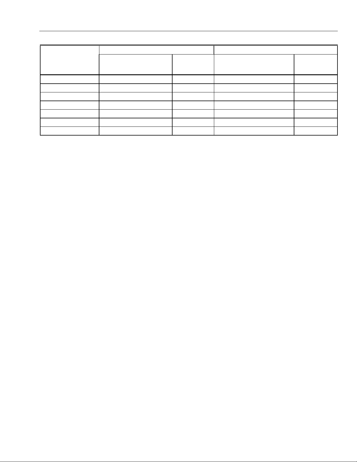
EXCEL 10 W7751B,D,F,H VAVII CONTROLLERS
Table D-1. Analog Points For Engineering Unit Selection.
English Units (Inch-Pound) Standard International Units (SI)
Abbreviations
Measured Item —
Temperature Degrees Fahrenheit F Degrees Celsius C
Relative Temperature Delta Degrees Fahrenheit DDF Degrees Kelvin K
Air Flow Cubic Feet per Minute CFM Meters Cubed per Hour m3h
Air Flow Velocity Feet per Minute FPM Meters per Second m/s
Area Square Feet Ft2 Square Meters m2
Length Inches in. Meters m
Differential Pressure Inches of Water Column Inw kiloPascal kPa
NOTE:
E-Vision - These points are displayed to the user and polled during the E-Vision monitor function. Monitor (M) indicates the
point appears in the Software list box. Schematic (S) indicates the point is to be displayed on the schematic air
handler diagram directly. Calibrate (C) - These points are calibratible and the calibration dialog (either the temperature
or air flow dialog) is displayed. These points are displayed in a listbox by selection of the menu item Controller,
Calibration. When the user double clicks on these points the calibration dialog is displayed. Parameter (P) - This
information is displayed to the user in the Application Selection screens. These fields are read/write when offline and
read only when online.
HW cfg - This information is displayed to the user in the Application Selection screens. These fields are read/write when offline
or online.
Manual - These points can be placed in the manual mode. When the user double clicks on these points the manual dialog is
displayed, this contains radio buttons; one for Auto and one for Manual.
Test (Test Mode) - These points are commandable when the controller is placed in the test mode via the menu item Controller,
Diagnostics, Test Mode. When the user enters this mode, a list box will display the points that can be commanded in
this mode.
(used in CARE
and E-Vision) —
Abbreviations
(used in CARE
and E-Vision)
87 74-2949–1
Page 88

EXCEL 10 W7751B,D,F,H VAVII CONTROLLERS
Table D1. Input/Output Points (Left).
Digita
l State
Engineering Units:
English (Metric) or
User Address NvName Fiel d Name States plus Range State Default
RawTempSen1 nvoIO siTempSensorS7(0) degrees F
-9 to 122
degrees C
(-22.8 to 50)
RawTempSen2 nvoIO siTempSensorS7(1) degrees F
-9 to 122
degrees C
(-22.8 to 50)
RawSpaceTemp nvoIO siSpaceTempS7 degrees F
40 to 100
degrees C
(4.4 to 37.8)
RawFlowVolts nvoIO siFlowVoltsS12 Volts
0 to 6.5
or
Value
of
SI_INVALID
SI_INVALID
SI_INVALID
SI_INVALID
FlowUncorrected nvoIO siFlowUncorrectedS3 -300 to 3500 FPM
(-1.5 to 17.5) m/s
FlowSensor nvoIO siFlowSensorS3 0 to 3500 FPM
(0 to 17.5) m/s
0
0
(continued)
74-2949–1 88
Page 89

EXCEL 10 W7751B,D,F,H VAVII CONTROLLERS
Table D1. Input/Output Points (Right).
Share (SH), Map (MA), Direct Access (DA)
E-Vision (EV): Cal ibrate (C), Monitor (M ),
Parameter (P), Schematic (S )
Hardware Configuration (HW),
Manual Point (MN), Test (TS)
EV SH MA DA HW MN TS Comments
M X X RawTempSen1 reports the current sens or readi ngs configured by TempInput1Type
X RawTempSen2 reports the current sens or readi ngs configured by TempInput1Type
X RawSpaceTemp is the meas ured space temperature. If t he sensor is not
X RawFlowVolts is the on board flow sensor velocity measured by the A/D after pre-
X FlowUncorrected is the air flow velocity measured by the on board flow sensor aft er
X X FlowSensor is t he ai r f l ow veloc i t y measured by the on-board flow sensor after zero
and TempInput2Type.
NOTE: The reported temperature does not include the offset c orrection added
during sensor calibration, TempInput1Cal or TempInput2Cal .
and TempInput2Type.
NOTE: The reported temperature does not include the offset c orrection added
during sensor calibration, TempInput1Cal or TempInput2Cal .
configured or has failed, the val ue i s SI_INVALID.
NOTE: The reported temperatures does not includes the offset correction
SpaceTempCal.
amplification and s caling. If a flow sensor error has been detected, RawFlowVolts is
set to SI_INVALID.
zero correction and linearization. If a FlowError has been detected or
ConfigPressDep (Press_Dependent i n E -Vision) = TRUE, then FlowUncorrected is
set to SI_INVALID.
calibration, linearization, and field corrections. If there is an error, then FlowSensor
is set to SI_INVALID.
(continued)
89 74-2949–1
Page 90

EXCEL 10 W7751B,D,F,H VAVII CONTROLLERS
Table D1. Input/Output Points (Left Continued).
Digital
State
Engineering Units:
User Address NvName Fiel d Name States plus Range State Default
DigOutputByte nvoIO ubOut
Byte Offset = 12
Bit Offset = 0
(DigitalOut1-8)
DigInputByte nvoIO ubDigitalIn
Byte Offset = 13
Bit Offset = 7
(DigitalIn1-4)
OccupancySnsr nvoIO OccupancySensor FALSE
English (Metric) or
FALSE
TRUE
FALSE
TRUE
TRUE
or
Value
of
0
1
0
1
0
1
FALSE
FALSE
FALSE
WindowSensr nvoIO WindowOpen FALSE
TRUE
HeatCoolCOSw nvoIO HeatCoolSwitch FALSE
TRUE
FreeDigInput nvoIO MonSwitch FALSE
TRUE
IOTestSwitch nvoIO IOTestSwitch FALSE
TRUE
OverrideInput nvoIO OverRide FALSE
TRUE
Model nvoIO Model UNKNOWN_MODEL
SMALL_MODEL
MED_MODEL
LARGE_MODEL
RawData0 nvoIO raw_data(0) 0 to 65535 0
RawData1 nvoIO raw_data(1) 0 to 65535 0
0
1
0
1
0
1
0
1
0
1
0
1
2
3
FALSE
FALSE
FALSE
FALSE
FALSE
UNKNOWN_MODEL
74-2949–1 90
(continued)
Page 91

EXCEL 10 W7751B,D,F,H VAVII CONTROLLERS
Table D1. Input/Output Points (Right Continued).
Share (SH), Map (MA), Direct Access (DA)
E-Vision (EV): Cal ibrate (C), Monitor (M ),
Parameter (P), Schematic (S )
Hardware Configuration (HW),
Manual Point (MN), Test (TS)
EV SH MA DA HW MN TS Comments
DigOutputByte - Bit Off set = 0 (DigitalOut1) DigOutputB yt e i s a byte with a bit
representing the state of every physical digital output
0 (FALSE).
(DigitalOut1 through DigitalOut 8).
DigInputByte Bit Off set = 7 (DigitalIn1): DigInput Byte is a byte with a bit for every
physical digital input. If the input is shorted t o ground, the bit is a 0 or FALSE. If the
input is open, the bit is 1 or TRUE. (DigitalIn1 through Digital In4).
.
On is a 1 (TRUE) and off is a
M X X OccupancySnsr is the state of the digital input configured and wired to the local
X WindowSensr is t he s tate of the digital input c onfigured and wired to a window open
X HeatCoolCOSw is the state of t he di gi tal input configured and wired to a Heat/Cool
X FreeDigInput is the state of the digital input conf i gured and wired to a general
X OverrideInput indicates t he s tatus of the wall module override pus hbutton. It is 1
C Model: The hardware configuration is encoded as a res i stor value connected to an
M
S
occupancy sensor. 1 m eans that occupancy is being sensed (input circuit s hort ed)
and 0 means that no occupanc y i s being sensed (input circuit open).
sensor switch. A 1 (input open circuit) means that the window is open, and 0 (input
shorted) means that t he window is cl osed
change over switch. The state of Heat Cool COSw is shown below:
FALSE (open): select Cool Mode
TRUE (closed): select Heat Mode
.
purpose monitor switch
open) means that the switc h i s open.
IOTestSwitch is the state of the digital input configured and wired to a IO test input.
The state of IOTestS witc h i s shown below:
FALSE (open): Normal operation
TRUE (closed): If Model is Large, perform stand-alone IO t est.
(TRUE) if the button is pres s ed, and is 0 (FALSE) if it i s not pressed.
analog resistive input. Model reports the detected hardware configuration.
(SMALL_MODEL is the W7751H SmartVAV Actuator. LARGE_MODEL is the
W7751D,F VAV Controllers and the W7751B OEM VAV Controller.)
RawData0 represents the A/D counts from the analog inputs. The c ounts represent
the measured time duri ng the second part of each A/D c onversion cycle and can be
used during testing of the A / D.
RawData1 represents the A/D counts from the analog inputs. The c ounts represent
the measured time duri ng the second part of each A/D c onversion cycle and can be
used during testing of the A / D.
1 (input shorted) means that switch is closed, and 0 (i nput
.
(continued)
91 74-2949–1
Page 92

EXCEL 10 W7751B,D,F,H VAVII CONTROLLERS
Table D1. Input/Output Points (Left Continued).
Digital
State
Engineering Units:
English (Metric) or
User Address NvName Field Name States plus Range State Default
RawData2 nvoIO raw_data(2) 0 to 65535 0
RawData3 nvoIO raw_data(3) 0 to 65535 0
RawData4 nvoIO raw_data(4) 0 to 65535 0
RawData5 nvoIO raw_data(5) 0 to 65535 0
RawData6 nvoIO raw_data(6) 0 to 65535 0
RawData7 nvoIO raw_data(7) 0 to 65535 0
or
Value
of
(continued)
74-2949–1 92
Page 93

EXCEL 10 W7751B,D,F,H VAVII CONTROLLERS
Table D1. Input/Output Points (Right Continued).
Share (SH), Map (MA), Direct Access (DA)
E-Vision (EV): Cal ibrate (C), Monitor (M ),
Parameter (P), Schematic (S )
Hardware Configuration (HW),
Manual Point (MN), Test (TS)
EV SH MA DA HW MN TS Comments
RawData2 represents the A/D counts from the analog inputs. The c ounts
represent the measured time during the second part of each A/D conversion cycle
and can be used during testing of t he A /D.
RawData3 represents the A/D counts from the analog inputs. The c ounts
represent the measured time during the second part of each A/D conversion cycle
and can be used during testing of t he A /D.
RawData4 represents the A/D counts from the analog inputs. The c ounts
represent the measured time during the second part of each A/D conversion cycle
and can be used during testing of t he A /D.
RawData5 represents the A/D counts from the analog inputs. The c ounts
represent the measured time during the second part of each A/D conversion cycle
and can be used during testing of t he A /D.
RawData6 represents the A/D counts from the analog inputs. The c ounts
represent the measured time during the second part of each A/D conversion cycle
and can be used during testing of t he A /D.
RawData7 represents the A/D counts from the analog inputs. The c ounts
represent the measured time during the second part of each A/D conversion cycle
and can be used during testing of t he A /D.
(continued)
93 74-2949–1
Page 94

EXCEL 10 W7751B,D,F,H VAVII CONTROLLERS
Table D2. Control Parameters (Left).
Digital
State
Engineering Units:
English (Metric) or
User Address NvName Fiel d Name States plus Range State Default
nviInUse 0 to 65534 0
or
Value
of
DestFlowOffset nviFlowOff set -2119 to 2119 CFM
(-3600 to 3600) m3h
BypassTime nciAux1SetPt ubBypassTime minutes
0 to 1080
StptLoLim nciAux1SetPt siLowStPtS7 degrees F
-9 to 90
degrees C
(-22.8 to 32.2)
StptHiLim nciAux1SetPt siHighStPtS7 degrees F
-9 to 90
degrees C
(-22.8 to 32.2)
0
180
55
85
(continued)
74-2949–1 94
Page 95

EXCEL 10 W7751B,D,F,H VAVII CONTROLLERS
Table D2. Control Parameters (Right).
Share (SH), Map (MA), Direct Access (DA)
E-Vision (EV): Cal ibrate (C), Monitor (M ),
Parameter (P), Schematic (S )
Hardware Configuration (HW),
Manual Point (MN), Test (TS)
EV SH MA DA HW MN TS Comments
nviInUse: This is used by a management node to indicate to any other management
node that it is logged on to the E xcel 10 node and that they should not try to int eract
with any of the Excel 10s network variables. B efore the management node reads or
writes any network variables, the management node checks nviInUse for a zero value
meaning no other management nodes are already logged on and that a management
node can log on to the node. Then the management node writes a number, 1 through
65534, to nviInUse and periodically writes the same value to indicate that the
management node is still logged on. If there are no writes made to nviInUse for
approximately 60 seconds, then the Excel 10 resets nviInUse to zero t o automatically
log off the management node. Before interacting with any net work variabl es, the
management node verifies that the nviInUse has not changed. The management node
logs off by writing 0 to nviInUse.
During power up, an application restart, or return to on-line from off-li ne, the Excel 10
sets nviInUse to 65535 to i ndi cate to the management node that it has returned to online.
M X X X X DestFlowOffset is us ed by a bui l di ng management node to alter the S aFl owCntlSpt for
M
P
M
P
M
P
improved air quality. In s ome operating modes, Des t Fl owOff set is added to the
minimum f l ow set tings to increase the air fl ow when DestFlowOffset is positive.
BypassTime is t he time between the pressing of t he overri de but ton at the wall
module (or initiating Bypass via DestManualOcc) and the return t o the original
occupancy state. When the bypass st at e has been activated, the bypass timer is set
to BypassTime.
StptLoLim is t he l owest val ue report ed by the setpoint knob. Dependent on the
configuration of the set poi nt knob this setting is ei ther direct (degrees Fahrenheit or
Celsius) in case of direc t setpoint knob configurat i on or offset (Delta Degrees or
Degrees Kelvin) in case of off set setpoint knob confi guration. If the StptLoLi m is
outside the range shown below, or if StptLoLi m is greater than StptHiLi m, the limit s
shown below are used instead.
Offset: Low Limit =-9°F (-5°C), High Limit = +9°F (+5°C)
Direct: Low Limit = 55°F (12.8° C), Hi gh Li mit = 85°F (24.4°C)
StptHiLim is the highest value reported by the setpoint knob. Dependent on the
configuration of the set poi nt knob this setting is ei ther direct (degrees Fahrenheit or
Celsius) in case of direc t setpoint knob configurat i on or offset (Delta Degrees or
Degrees Kelvin) in case of off set setpoint knob confi guration. If the StptHi Li m is
outside the range shown below, or if StptLoLi m is greater than StptHiLi m, the limit s
shown below are used instead.
Offset: Low Limit = -9°F (-5°C), High Limit = +9°F (+5°C)
Direct: Low Limit = 55°F (12.8° C), Hi gh Li mit = 85°F (24.4°C)
(continued)
95 74-2949–1
Page 96

EXCEL 10 W7751B,D,F,H VAVII CONTROLLERS
Table D2. Input/Output Points (Left Continued).
Digital
State
Engineering Units:
English (Metric) or
User Address NvName Field Name States plus Range State Default
DlcBumpTemp nciAux1SetPt ubDlcBumpTempS1 0 to +10 degrees F
0 to +5.6 degrees C
or
Value
of
3
FlowTrackOfst nciAux1SetPt siTrackModeOffsetS O -2119 to 2119 CFM
(-3600 to 3600) m3h
PeriphPos nciAux1SetPt ubPeriphMinPosS1 percentage
0 to 100
WinOpnDmprPos nciAux1SetPt ubWinOpenPosS1 percentage
0 to 100
0
0
0
MinDmprPos nciAux1SetPt ubMinDamperPosS1 percentage
0 to 100
MaxDmprPos nciAux1SetPt ubMaxDamperPos S 1 percentage
0 to 100
ReHeatDmprPos nciAux1Set Pt ubReHeatDamperPosS1 percentage
0 to 100
StdbyDmprPos nciAux1SetP t ubStdbyDamperPosS1 percentage
0 to 100
74-2949–1 96
0
100
50
50
(continued)
Page 97

EXCEL 10 W7751B,D,F,H VAVII CONTROLLERS
Table D2. Control Parameters(Right Continued).
Share (SH), Map (MA), Direct Access (DA)
E-Vision (EV): Cal ibrate (C), Monitor (M ),
Parameter (P), Schematic (S )
Hardware Configuration (HW),
Manual Point (MN), Test (TS)
EV SH MA DA HW MN TS Comments
M
P
M
P
M
P
M
P
M
P
M
P
M
P
M
P
DlcBumpTemp specifies the amount of shift in the controlled space temperature
when demand limit control (Des tDlcShed) is active. See DestDlcShed for more
details.
FlowTrackOfst: When the Mode is FLOW_TRA CK ING, the air flow setpoint is
FlowTrackOfst plus DestFlowTrack.
PeriphPos sets the minimum peripheral reheat val ve position as shown below.
This feature allows the user to maintain flow in pipes that c an ot herwis e f reeze.
Reheat Types:
No_Local_Reheat.
Elec_OneStage.
Elec_TwoStage.
Elec_ThreeStage.
Elec_ThreeStageBin.
Elec_OneStagePeriph.
Float_Reheat: Minimum position of the floating reheat val ve.
Float_Periph: Minimum position of the floati ng peri pheral heat valve.
Float_Reheat_Periph: Minimum position of the floating peripheral heat valve.
Float_Periph_Reheat: Minimum position of the floating peripheral heat valve.
PWM_Reheat: Minimum position of the P ul se Width Modulation peri pheral heat
valve.
PWM_Periph: Minimum position of t he P ul se Width Modulation peri pheral heat
valve.
PWM_Reheat_Periph: Mini mum position of t he Pulse Width Modulat i on peri pheral
heat valve.
PWM_Periph_Reheat: Mini mum position of t he Pulse Width Modulat i on peri pheral
heat valve.
DualDuctReheat: Either Float HotDuctPrDep or Float_Reheat.
WinOpnDmprPos: The five configuration parameters WinOpnDmprPos,
MinDmprPos, MaxDmprPos, ReheatDmprPos, and StdbyDmprPos set li mits on
the damper posistion when ConfigP ressDep (Press_Dependent in E-Vision) is
TRUE or when the flow sensor has failed. The fol l owing relat i onships must be true
for the control to work properly.
MinDmprPos < MaxDmprPos
StdbyDmprPos < MaxDmprPos
ReheatDmprPos < MaxDmprPos
WinOpnDmprPos < MaxDmprPos
MinDmprPos: (See descri ption for WinOpnDmprPos above)
MaxDmprPos: (See description f or WinOpnDmprPos above)
ReheatDmprPos: (See description for Wi nOpnDmprPos above)
StdbyDmprPos: (S ee description for WinOpnDmprPos above)
(continued)
97 74-2949–1
Page 98

EXCEL 10 W7751B,D,F,H VAVII CONTROLLERS
Table D2. Control Parameters (Left Continued).
Digital
State
Engineering Units:
English (Metric) or
User Address NvName Field Name States plus Range State Default
PressDmprPos nciAux1SetPt ubPressurizeS1 percentage
0 to 100
or
Value
of
100
DepressDmprPos nciAux1SetPt ubDePressurizeS1 percentage
0 to 100
PurgeDmprPos nciAux1SetPt ubNi ght PurgeS1 percentage
0 to 100
WarmupDmprPos nciAux1SetPt ubMornWarmS1 percent age
0 to 100
TempRamp nciAux1SetPt UbTempRampS0 0 to 36°F per Hour
0 to 20°C per Hour
FanEnableFlow nciAux1SetPt UiFanEnableFlowS0 0 to 10,000 CFM
(0 to 16,990) m3h
FreshAirReq nciAux1SetPt UiFreshAirRequiredS0 0 to 10,000 CFM
(0 to 16,990) m3h
GainCoolProp nciAux2SetPt ubTrCoolS2 1 to 20 degrees F
1 to 10.6 degrees C
GainHeatProp nciA ux2SetP t ubTrHeatS2 2 to 30 degrees F
1 to 17 degrees C
GainCoolInt nciAux2SetP t SiItCoolS0 seconds
0 to 5000
GainHeatInt nciAux2SetPt SiItHeatS0 seconds
0 to 5000
GainCoolDer nciAux2SetPt UbDtCoolS0 seconds
0 to 255
GainHeatDer nciAux2SetPt UbDtHeatS0 seconds
0 to 255
0
50
50
4
0
0
3
5
4000
2400
0
0
(continued)
74-2949–1 98
Page 99

EXCEL 10 W7751B,D,F,H VAVII CONTROLLERS
Table D2. Control Parameters (Right Continued).
Share (SH), Map (MA), Direct Access (DA)
E-Vision (EV): Cal ibrate (C), Monitor (M ),
Parameter (P), Schematic (S )
Hardware Configuration (HW),
Manual Point (MN), Test (TS)
EV SH MA DA HW MN TS Comments
M
P
M
P
M
P
M
P
M
P
M
P
M
P
PressDmprPos: The four configuration parameters PressDmprPos,
DepressDmprPos, PurgeDmprPos, and WarmupDmprPos set l i mits on the
damper position when ConfigPress Dep (P ress_Dependent in E-Vision) is TRUE.
When ConfigPressDep (Press_Dependent in E-Visi on) i s FALSE, they set the
limits on the air f l ow as a perc entage of the range between zero and MaxFlowSpt.
DepressDmprPos: (See description for PressDmprPos above).
PurgeDmprPos: (See description for PressDm prP os above).
WarmupDmprPos: (See description for PressDmprP os above).
When EffectOcc is OC_UNOCCUPIE D and the NextState is OC_OCCUPIED,
then the setpoint is of f set by a value Ramp depending on TempRamp, the
CmdTUNCOS and the current CoolOc cSpt or HeatOccSpt and CoolUnoc cSpt or
HeaUnoccSpt.
FanEnableFlow: When the FanType is P aral lel _Fl ow, FanEnableFl ow is us ed to
determine when there is enough air flow from the main air handler to turn the fan
off.
FreshAirReq is the desired amount of fresh air required for this zone.
M
P
M
P
M
P
M
P
M
P
M
P
GainCoolProp is the throttl i ng range f or the cooling control loop.
GainHeatProp is the throttl i ng range for the heating control loop.
GainCoolInt is the integral time for the cooling c ont rol l oop.
GainHeatInt is the integral time for the heating cont rol l oop.
GainCoolDer is the derivative time for the cooling control loop.
GainHeatDer is the derivative time for the heating control loop.
(continued)
99 74-2949–1
Page 100

EXCEL 10 W7751B,D,F,H VAVII CONTROLLERS
Table D2. Control Parameters (Left Continued).
Digital
State
Engineering Units:
English (Metric) or
User Address NvName Field Name States plus Range State Default
CorrDmpr10 nciAux2SetPt ubDamperDrive0 0 to 10 t i mes 0.1 sec. 0
or
Value
of
CorrDmpr20 nciAux2SetPt ubDamperDrive1 0 to 10 t i mes 0.1 sec. 0
CorrDmpr30 nciAux2SetPt UbDamperDrive2 0 to 10 tim es 0.1 sec. 0
CorrDmpr40 nciAux2SetPt UbDamperDrive3 0 to 10 tim es 0.1 sec. 1
CorrDmpr50 nciAux2SetPt UbDamperDrive4 0 to 10 tim es 0.1 sec. 1
CorrDmpr60 nciAux2SetPt UbDamperDrive5 0 to 10 tim es 0.1 sec. 1
CorrDmpr70 nciAux2SetPt UbDamperDrive6 0 to 10 tim es 0.1 sec. 1
CorrDmpr80 nciAux2SetPt UbDamperDrive7 0 to 10 tim es 0.1 sec. 2
CorrDmpr90 nciAux2SetPt UbDamperDrive8 0 to 10 tim es 0.1 sec. 3
CorrDmpr100 nciAux2SetPt UbDamperDrive9 0 to 10 tim es 0.1 sec. 5
(continued)
74-2949–1 100
 Loading...