

Page 1

74-2958-1
yrig
Excel 10
g
g
(
g
g
y
g
y
y (
y
y
g
W7750A,B,C CONSTANT VOLUME AHU CONTROLLER
SYSTEM ENGINEERING
Contents
Introduction.................................................................................................................................. 6
Description of Devices.......................................................................................... 6
Control Application........................ ...... ................................................................. 7
Control Provided................................................................................................... 7
Products Covered................................................................................................. 8
anization of Manual........................................................................................ 8
Or
Applicable Literature.................................. ..... ...... ................................................ 8
Product Names..................................................................................................... 9
ency Listings .................................................................................................... 9
A
Abbreviations and Definitions............................................................................... 10
Construction......................................................................................................... 11
Controllers ...................................................................................................... 11
PERFORMANCE SPECIFICATIONS......................................................... 13
ONMARK
L
Inputs/Outputs: ............................................................................................... 18
ANALOG INPUTS:...................................................................................... 18
DIGITAL INPUTS:....................................................................................... 19
TRIAC OUTPUTS ON THE
DIGITAL OUTPUTS:................................................................................... 19
Wall Modules .................................................................................................. 20
Duct Sensor .................................................................................................... 20
urations...................................................................................................... 22
Confi
General ........................................................................................................... 22
Allowable Heatin
STAGED HEATING/COOLING CONTROL................................................ 24
MODULATING HEATING/COOLING CONTROL....................................... 24
HEAT PUMP CONTROL............................................................................. 24
ECONOMIZER CONTROL......................................................................... 25
PNEUMATIC ACTUATOR CONTROL........................................................ 25
MIXED-OUTPUT-TYPE CONTROL........................................................... 26
Occupanc
Window Open/Closed Di
Wall Module Options ....................................................................................... 26
Filter Monitor .......................................................................................... 27
Dirt
Indoor Air Qualit
Smoke Control ................................................................................................ 27
Freeze Stat ..................................................................................................... 27
Modes of Operation.............................................................................................. 27
® Functional Profile..................................................................... 17
W7750B,C MODELS ONLY):........................ 19
and Cooling Equipment Configurations ............................ 24
Sensor ......................................................................................... 26
ital Input ................................................................. 26
IAQ) Override .. ...... ........................................................... 27
Application Steps.................................................................................................................................. 29
Overview .............................................................................................................. 29
Step 1. Plan the S
Step 2. Determine Other Bus Devices Required.................................................. 29
Step 3. La
L
Power Wiring .................................................................................................. 32
Step 4. Prepare Wirin
® U.S. Registered Trademark
ht © 2000 Honeywell Inc. • All Rights Reserved
Cop
Out Communications and Power Wiring........................................... 30
ONWORKS
POWER BUDGET CALCULATION EXAMPLE .......................................... 32
LINE LOSS...................................... ..... ...... ..... ...... ..................................... 33
stem....................................................................................... 29
® Bus Layout ................................................................................ 30
Diagrams......................................................................... 35
Page 2

EXCEL 10 W7750A,B,C CONSTANT VOLUME AHU CONTROLLER
q
g
g
g
y
g
g
g
q
(
(
y
y
y
y
y
y
(
(
y
(
(
g
g
g
g
g (
g
y (
g
(
g
y
g
General Considerations .................................................................................. 35
W7750 Controllers .......................................................................................... 36
FACTORY DEFAULT DIGITAL OUTPUTS:................................................ 37
ONWORKS
L
Step 5. Order E
® Bus Termination Module ........................................................... 43
uipment ..................................................................................... 45
Step 6. Configure Controllers............................................................................... 48
Step 7. Troubleshootin
Troubleshootin
Excel 10 Controllers and Wall Modules ............................... 48
Temperature Sensor and Setpoint Potentiometer Resistance Ranges .......... 49
Alarms ............................................................................................................ 49
Broadcastin
the Service Message ................................................................ 50
W7750 Controller Status LED ........................................................................ 50
T7770C,D Wall Module B
T7560A,B Di
ital Wall Module Bypass Pushbutton and LCD Display Occupancy
Symbols .......................................................................................................... 51
Appendices.................................................................................................................................. 51
Appendix A. Usin
E-Vision to Commission a W7750 Controller......................... 51
Sensor Calibration .......................................................................................... 51
the Pid Parameters ............................................................................ 51
Settin
Appendix B. Se
uences of Operation. ................................................................. 52
Common Operations ........................ ............................................................. . 53
Room Temperature Sensor
Remote Setpoint
Setpoint Limits (LoSetptLim and HiSetptLim)............................................. 55
pass Mode (StatusOvrd and StatusLed)................................................ 55
B
BYPASSTIME............................................................................................. 55
OverrideT
OverridePriorit
cles per Hour (ubHeatCph and ubCoolCph).......................................... 55
C
pe.............................................................................................. 55
........................................................................................... 55
T7770C,D or T7560A,B Wall Module Bypass Pushbutton Operation......... 55
Standb
Mode (StatusOcySen).................................................................. 56
Continuous Unoccupied Mode ................................................................... 56
Occupanc
Time Clock
Mode and Manual Override Arbitration.................................... 56
Occ_Time_Clock)................................................................... 57
Schedule Master
Setpoint Ramping....................................................................................... 57
Recover
Ramping for Heat Pump Systems.............................................. 57
Fan Operation............................................................................................. 58
Window Sensor
Smoke Control............................................................................................ 58
Demand Limit Control
Dirty Filter Monitor...................................................................................... 59
Start-Up...................................................................................................... 59
Temperature Control Operations .................................................................... 59
ed Cooling Control .............................................................................. 60
Sta
ed Heating Control.............................................................................. 60
Sta
Cascade Control of Modulatin
Series 60 Modulatin
Pulse Width Modulatin
Outdoor Air Lockout of Heatin
Economizer Damper Control ...................................................................... 61
Indoor Air Qualit
Freeze Stat................................................................................................. 62
Dischar
e Air Low Limit Control................................................................. 62
Economizer Enable/Disable Control........................................................... 62
Appendix C. Complete List of Excel 10 W7750 Controller User Addresses. ....... 62
User Address Indexes
Mappable User Addresses and Table Number ............................................... 64
Failure Detect User Addresses and Table Number ........................................ 65
Appendix D. Q7750A Excel 10 Zone Mana
Approximate Memor
Appendix E. Sensor Data for Calibration. ............................................................110
Resistance Sensors. ...................................................................................... 110
e/Current Sensors. ............................................................................... 112
Volta
....................................................................................... 48
pass Pushbutton and Override LED ..................... 51
RmTemp)....................................................... 54
RmtStptPot)................................................................... 55
Sched_Master).............................................................. 57
StatusWndw)................................................................... 58
DLC)...................................................................... 58
Cooling/Heating........................................ 61
Control..................................................................... 61
PWM) Control..................................................... 61
/Cooling..................................................... 61
IAQ) Override ............................................................... 62
all in alphabetical order) ............................................ 63
er Point Estimating Guide...............109
Size Estimating Procedure. .........................................1 09
72-2958—12
Page 3

EXCEL 10 W7750A,B,C CONSTANT VOLUME AHU CONTROLLER
g
g
g
g
g
g
g
g
greyed)
g
g
g
g
g
g
g
g
g
g
g
g
g
g
g
g
g
g
g
g
g
(
g
g
)
g
g
g
g
g
g
g
g
g
g
g
(
g
g
g
g
g
g
g
g
g
g
g
List of Figures
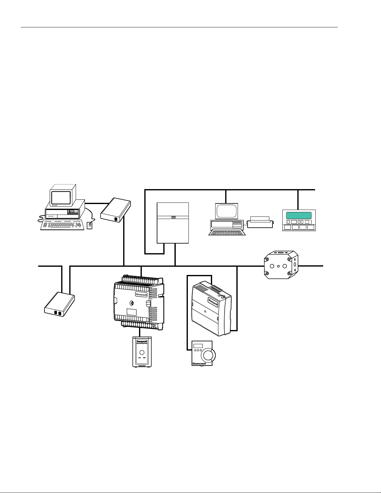
Fig. 1. Typical system overview. ................................................................................................................................................ 6
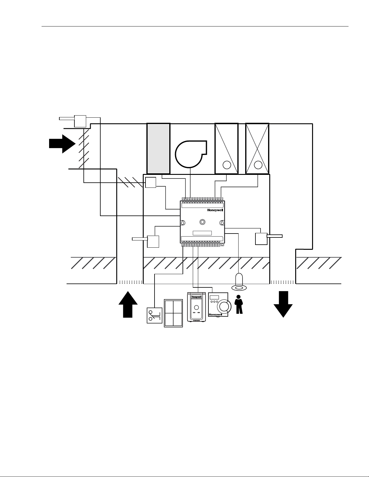
. 2. Typical W7750 control application. ................................................................................................................................. 7
Fi
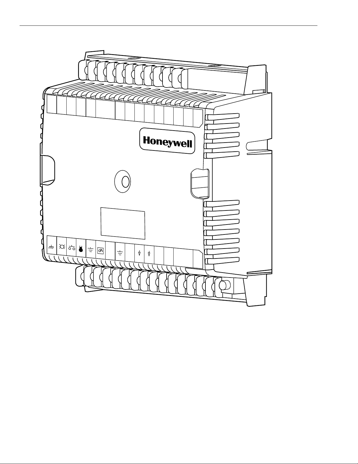
. 3. Excel 10 W7750A Constant Volume AHU Controller. ..................................................................................................... 12
Fi
Fi
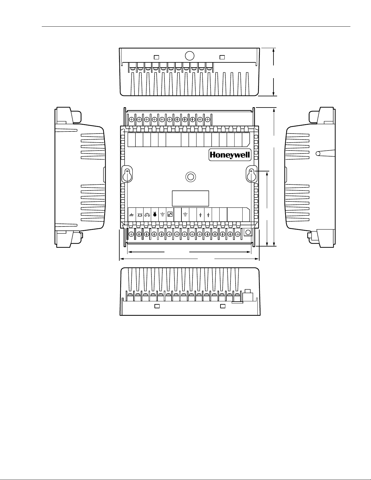
. 4. W7750A construction in in. (mm). ................................................................................................................................... 13
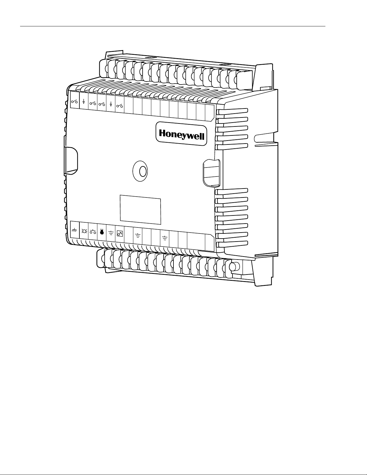
. 5. Excel 10 W7750B Constant Volume AHU Controller. ..................................................................................................... 14
Fi
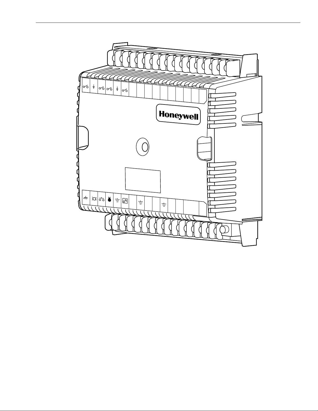
. 6. Excel 10 W7750C Constant Volume AHU Controller. .................................................................................................... 15
Fi
Fi
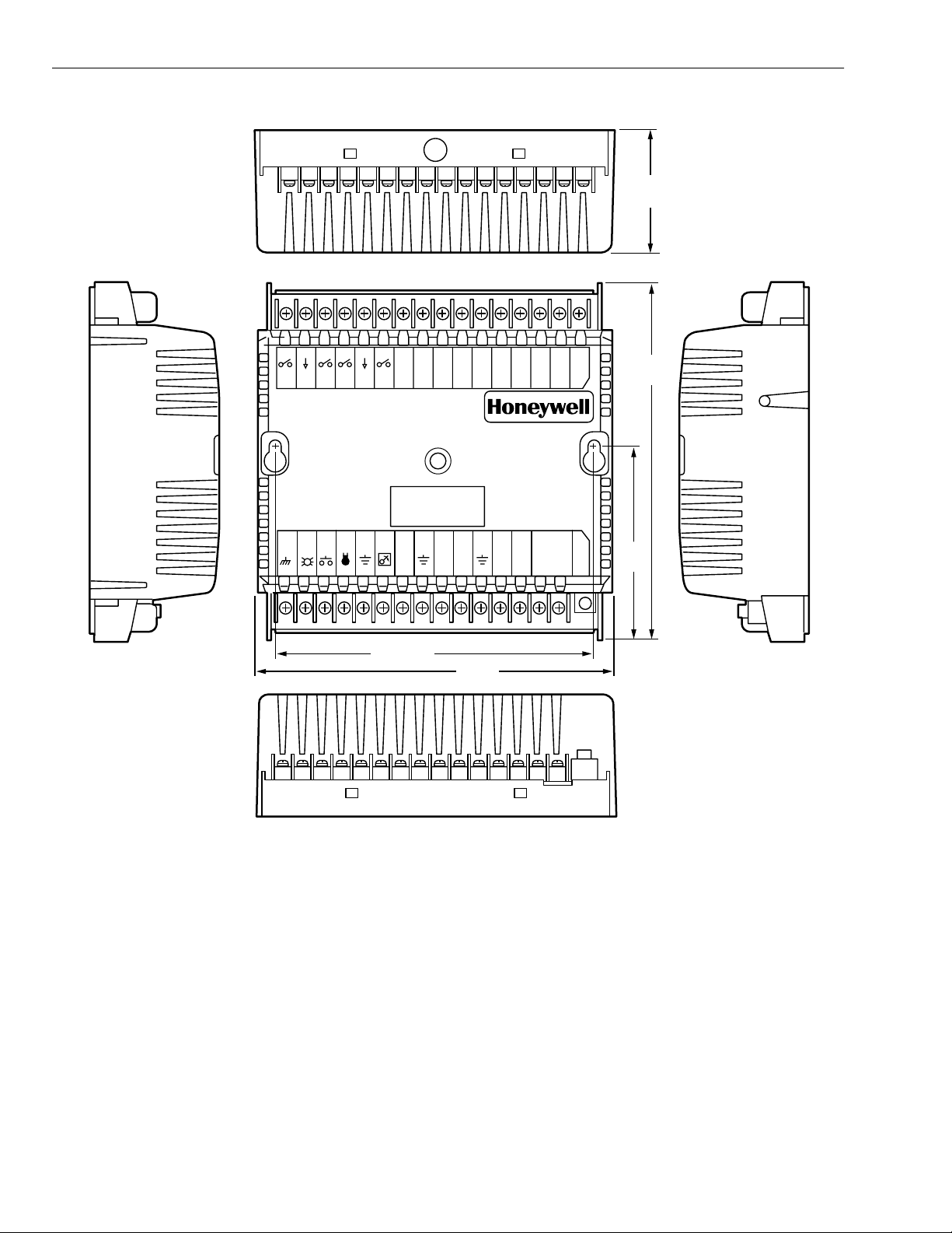
. 7. W7750B,C construction in in. (mm). W7750C (shown) has three 4 to 20 mA analog outputs.) ..................................... 16
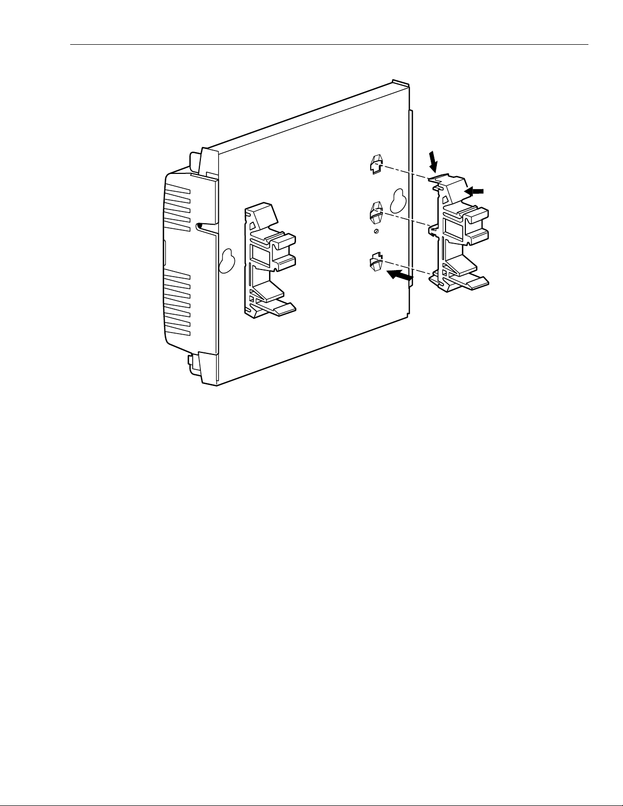
. 8. DIN rail adapters. ............................................................................................................................................................ 17
Fi
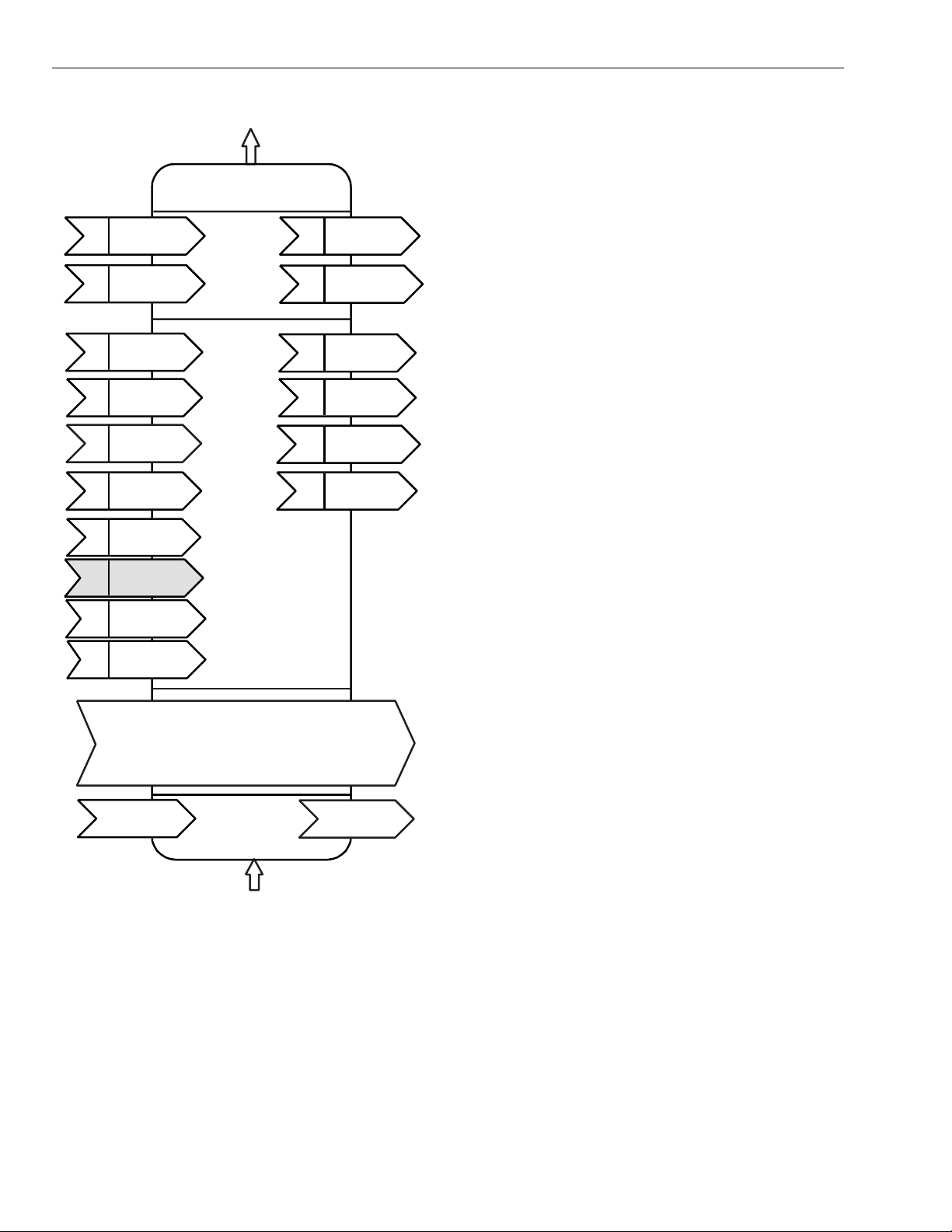
. 9. Functional profile of LONM
Fi
are
. 10. T7770A,B,C,D construction in in. (mm). ....................................................................................................................... 20
Fi
. 11. T7560A,B construction in in. (mm). ............................................................................................................................... 21
Fi
Fi
. 12. C7770A construction in in. (mm). ............................... ...... .............................................................. ............................... 21
. 13. Fan with two stages of heating and two stages
Fi
of coolin
Fi
. 14. Fan, modulating heating and modulating cooling. ......................................................................................................... 24
. 15. Heat pump with two compressors and auxiliary heat stage(s)....................................................................................... 25
Fi
. 16. Economizer control. ...................................................................................................................................................... 25
Fi
Fi
. 17. Modulating heat with pneumatic valve actuator............................................................................................................. 26
. 18. Connecting the portable operator terminal
Fi
to the L
Fi
. 19. Wiring layout for one doubly terminated daisy-chain LONW
. 20. Wiring layout for two singly terminated LONW
Fi
. 21. NEMA class 2 transformer voltage output limits............................................................................................................ 34
Fi
Fi
. 22. Power wiring details for one Excel 10 per transformer. ................................................................................................. 34
. 23. Power wiring details for two or more Excel 10s per transformer. .................................................................................. 34
Fi
. 24. Transformer power wiring details for one Excel 10 used in UL 1995 equipment (U.S. only)......................................... 35
Fi
Fi
. 25. Attaching two or more wires at terminal blocks.............................................................................................................. 36
. 26. W7750B High-Side/Low-Side selectable switching and jumper location.............................................................. ...... ... 36
Fi
. 27. Typical W7750A Controller AHU application wiring diagram. (For more information on note 2,
Fi
refer to Fi
. 28. Typical W7750A Controller with separate transformer application wiring diagram.
Fi
........................................................................................................................................................................ 18
........................................................................................................................................................................... 24
ONWORKS
® Bus..................................................................................................................................................... 29
. 25.)................................................................................................................................................................ 38
For more information on note 2, refer to Fig. 25.)............................................................................................................ 38
Fi
. 29. W7750A Controller floating economizer damper wiring diagram. (For more information on note 2, refer to Fig. 25.)... 39
. 30. Typical W7750B Controller wi th staged heating and cooling wiring diagram. (For more information on note 2, ref er to Fig.
Fi
.................................................................................................................................................................................... 40
25.
Fi
. 31. W7750B Controller with floating heating, cooling and economizer wiring diagram. (For more information on note 2, refer
. 25.)......................................................................................................................................................................... 40
to Fi
. 32. W7750B,C Controller PWM damper actuator wiring diagram. (For more information on note 2, refer to
Fi
Fi
. 25.)............................................................................................................................................................................. 41
. 33. W7750B,C wiring diagram with 4 to 20 mA enthalpy sensors and digital inputs. (For more information on note 2, refer to
Fi
. 25.)............................................................................................................................................................................. 41
Fi
Fi
. 34. W7750B,C wiring diagram with C7600C 4 to 20 mA solid state humidity sensor. (For more information on note 2, refer to
. 25.)............................................................................................................................................................................. 42
Fi
. 35. W7750C Controller with 4-to-20 mA heating, cooling and economizer wiring diagram. AOs must use terminals 16, 17 or
Fi
18. The AOs can be set to be reverse actin
. 36. Pneumatic transducer to W7750B,C
Fi
B shown, see triangle note 4). ......................................................................................................................................... 43
Fi
. 37. RP7517,B pneumatic transducer to W7750C................................................................................................................ 43
. 38. Typical doubly terminated daisy-chain LONW
Fi
. 39. LONW
Fi
Fi
. 40. Temperature sensor resistance plots............................................................................................................................. 49
. 41. Location of the Service Pin Button................................................................................................................................. 50
Fi
. 42. LED location on W7750. ................................................................................................................................................ 51
Fi
Fi
. 43. The T7770C,D Wall Modules LED and Bypass pushbutton locations........................................................................... 51
. 44. The T7560A,B Digital Wall Module Bypass pushbutton location................................................................................... 51
Fi
. 45. LED and Bypass pushbutton operation. ....................................................................................................................... 56
Fi
Fi
. 46. Setpoint ramping parameters with ramp rate calculation............................................................................................... 57
. 47. Setpoint ramping parameters with setpoint calculation.................................................................................................. 58
Fi
ORKS
® Bus termination wiring options. ............................................................................................................... 45
ARK
® RTU object details (variables not implemented in Excel 10 CVAHU
ORKS
® Bus segment. ........................................................ 31
ORKS
® Bus segments............................................................................. 32
. (For more information on note 2, refer to Fig. 25.).................................... 42
ORKS
® Bus segment termination module wiring diagram. ..................... 44
3 74-2958—1
Page 4

EXCEL 10 W7750A,B,C CONSTANT VOLUME AHU CONTROLLER
g
g
g
g
g
g
g
g
g
g
g
g
g
g
g
g
Fig. 48. Setpoint ramping parameters with ramp rate calculation............................................................................................... 58
. 49. Schematic diagram for a typical W7750B Unit. .............................................................................................................59
Fi
Fi
. 50. Staged output control versus PID Error. ....................................................................................................................... 60
. 51. Point capacity estimate for Zone Manager. ..................................................................................................................109
Fi
. 52. Graph of Sensor Resistance versus Temperature............................................................................................. ........... . 110
Fi
Fi
. 53. Graph of Sensor Resistance versus Temperature............................................................................................. ........... . 110
. 54. Graph of Sensor Resistance versus Temperature............................................................................................. ........... . 111
Fi
. 55. Graph of Sensor Resistance versus Temperature............................................................................................. ........... . 111
Fi
Fi
. 56. Graph of Sensor Resistance versus Temperature............................................................................................. ........... . 112
. 57. Graph of Sensor Voltage versus Humidity...................................... ........... ........... ............ ........... ........... ...... ........... ...... 112
Fi
. 58. C7600C output current vs. humidity............................................................................................................................... 112
Fi
Fi
. 59. Graph of Sensor Current versus Enthalpy (volts)...................................... ........... ............ ........... ..... ............ ........... ...... 113
. 60. Partial psychometric chart for a C7400A Solid State Enthalpy Sensor. ........................................................................114
Fi
. 61. C7400A Solid State Enthalpy Sensor output current vs. relative humidity. ............................................................. ...... 114
Fi
Fi
. 62. Graph of Sensor Voltage versus CO2 concentration..................................................................................................... 115
. 63. Graph of Sensor Voltage versus input Voltage to A/D.................................................................................................. 115
Fi
. 64. Graph of Sensor Voltage (Vdc) versus Pressure (Inw).................................... ........... ........... ........... ............ ........... ..... . 116
Fi
74-2958—14
Page 5

EXCEL 10 W7750A,B,C CONSTANT VOLUME AHU CONTROLLER
g
g
g
g
g
g
g
y
g
y
gy
g
g
g
y (
g
g
ge (
List of Tables
Table 1. Agency Listing. ............................................................................................................................................................. 9
Table 2. List of Differences in W7750A and W7750B,C Controllers........................................................................................... 11
Table 3. Common Confi
Table 4. Confi
uration Options Summary For W7750A,B,C Controllers.................................................................................... 23
Table 5. Modes Of Operation For The Excel 10 W7750 Controller ........................................................................................... 27
Table 6. Application Steps.......................................................................................................................................................... 29
Table 7. L
ONWORKS
Table 8. VA Ratin
Table 9. Field Wirin
Table 10. W7750A Version I/O Description................................................................................................................................ 37
Table 11. Excel 10 W7750 Controller Orderin
Table 12. Excel 10 Alarms.......................................................................................................................................................... 49
Table 14. Common Confi
Table 15. Confi
Table 16. B
uration Options Summary For W7750A,B,C Controllers.................................................................................. 54
pass Pushbutton Operation.................................................................................................................................... 55
Table 17. Intersta
Table 18. Excel 10 W7750 Controller User
Address Point T
pes................................................................................................................................................................... 62
Table 20. Input/Output Points..................................................................................................................................................... 67
Table 21. Control Parameters..................................................................................................................................................... 73
Table 22. Ener
Management Points........................................................................................................................................ 78
Table 23. Status Points............................................................................................................................................................... 81
Table 24. Calibration Points........................................................................................................................................................ 93
Table 25. Confi
Table 26. L
uration Parameters........................................................................................................................................... 94
ONMARK
Table 27. Direct Access And Special Points..................................................................................................... ........... ............ ... 106
Table 28. Data Share Points.................................................................................................................................................... ... 108
Table 29. Sensor Resistance Versus Temperature.......................................................................................... ........... ............ ... 110
Table 30. Sensor Resistance Versus Temperature.......................................................................................... ........... ............ ... 110
Table 31. Sensor Resistance Versus Temperature.......................................................................................... ........... ............ ... 111
Table 32. Sensor Resistance Versus Temperature.......................................................................................... ........... ............ ... 111
Table 33. Sensor Resistance Versus Temperature.......................................................................................... ........... ............ ... 111
Table 34. Sensor Volta
Table 35. Sensor Volta
Table 36. Sensor Current Versus Enthalp
Table 37. Sensor Volta
Table 38. Sensor Volta
Table 39. Sensor Volta
uration Options Summary For W7750A,B,C Controllers..................................................................... 22
® Bus Configuration Rules And Device Node Numbers............................................................................. 30
s For Transformer Sizing.............................................................................................................................. 33
Reference Table (Honeywell listed as AK#### or equivalent).................................................................. 36
Information....................................................................................................... 46
uration Options Summary For W7750A,B,C Controllers................................................................... 53
e Minimum Times.......................................................................................................................................... 60
®/Open System Points................................................................................................................................ 97
e Versus Humidity................................................................................................................................ 112
e Versus Humidity................................................................................................................................ 112
volts)............................... ........... ........... ........... ...... ........... ........... ........... ............ ... 113
e Versus CO2 Concentration............................................................................................................... 115
e Versus Input Voltage To A/D............................................................................................................. 115
Vdc) Versus Pressure (Inw)........................... ........... ............ ........... ..... ............ ........... ........... ......... 116
5 74-2958—1
Page 6
(
g
g
y
g
g
y
j
y
g
g
g
(
g
y
y
Excel 10 W7750A,B,C Constant Volume AHU Controller
EXCEL 10 W7750A,B,C CONSTANT VOLUME AHU CONTROLLER
INTRODUCTION
Description of Devices
The W7750 is the Constant Volume Air Handling Unit
CVAHU) Controller in the Excel 10 product line family. The
CVAHU is a LONM
le zone and heat pump air handlers. W7750 systems
sin
control the space temperature in a
the heating and cooling equipment in the air handler that
delivers air to that space. The W7750 air handler is t
an all-in-one constant air volume packa
the roof of the building. In addition to standard heating and
control, the W7750 provides many options and
coolin
advanced s
stem features that allow state-of-the-art
commercial building control. The W7750 Contro ller is capa ble
of stand-alone operation; however, optimum functional
benefits are achieved when the network communication
capabilities are used. The W7750 utilizes the Echelon
ARK
compliant device designed to control
iven zone by regulating
ed unit, located on
Q7752A
ONWORKS BUS
L
SERIAL
ADAPTER
pically
ONWORKS
L
and conforms with the L
network (LONW
ORKS
ONMARK
Bus) for communications,
HVAC Interoperability
standard for Roof Top Unit Controllers (see Fig. 9).
The T7770 or T7560 direct-wired Wall Modules are used in
con
unction with W7750 Controllers. The zone controlled by
the W7750 Controller t
pically can use a T7770A thr ough D or
a T7560A,B Wall Module. Additional features available in
T7770A throu
override di
ONWORKS
L
h D models include analog setpoint input knob,
ital input pushbutton, override status LED and
Bus network access jack. Additional features
available in T7560A,B models include analog setpoint input
knob, override di
ital input pushbutton, humidity sensor
T7650B model), override status LCD and digital displ ay.
The Q7750A Excel 10 Zone Mana
interface that allows devices on the L
er is a communications
ONWORKS
Bus network
to communicate with devices on the standard EXCEL 5000
stem C-Bus. Fig. 1 shows an overview of a typical system
S
out. The Q7750A also provides some control and
la
monitoring functions.
C-BUS COMMUNICATION NETWORK
PERSONAL COMPUTER TOOLS
E-VISION
CARE
ONWORKS-BUS COMMUNICATIONS NETWORK
L
EXCEL 10
W7750B
CVAHU
CONTROLLER
Q7751A
FTT
ONWORKS BUS
L
ROUTER
EXCEL 10 T7770
WALL MODULE
31 30 29 28 27 26 25 24 23 22 21 20 19 18 17 16
1
234
567
89
10 11 12 13 1
415J3
Fig. 1. Typical system overview.
EXCEL 10
Q7750A
ZONE
MANAGER
C-BUS TO L
INTERFACE DEVICE
L
ONWORKS BUS COMMUNICATIONS NETWORK
ONWORKS BUS
EXCEL BUILDING SUPERVISOR
EXCEL 10 T7560A, B
WALL MODULE
EXCEL 10 W7751F
PANEL PLENUM
MOUNT VERSION
VARIABLE AIR VOLUME
CONTROLLER
EXCEL 500
Q7740A
2-WAY
REPEATER
M17487
74-2958—16
Page 7
EXCEL 10 W7750A,B,C CONSTANT VOLUME AHU CONTROLLER
g
g
(
y
g
g
g
g
g
g
g
g
(
y
g
g
g
q
g (
j
g
g
g
g
(
g
)
Control Application
W7750 systems in commercial build ings typically incorporate
a packaged air handler system that delivers a constant
volume of air at preconditioned temperatures to the zone
served. Each zone is usually serviced by a separate
bein
AHU; however, sometimes two or more AHUs service the
same zone. Note that the W7750 is not desi
Variable Air Volume
VAV) air handlers or Multi-Zone air
handlers, where one air handler simultaneously controls the
space temperature in man
OA TEMP
OUTDOOR
AIR
zones.
ned to control
FILTER
M
The W7750 can control sta
coils, mixed air economizer dampe rs, and the system
coolin
ed or modulating heating and
fan. Control of heat pump units, where the compressor(s) is
used for both coolin
and heating, is also provided. The zone
the W7750 services can use a T7770 or T7650 for space
temperature sensin
for users. Fi
FAN
and an LONW
. 2 shows a typical W7750 control application.
COOL
COIL
-
EXCEL 10
W7750
CVAHU
HEAT
COIL
+
ORKS
Bus network access
RA TEMP
RETURN
AIR
WINDOW CONTACT
Fig. 2. Typical W7750 control application.
Control Provide d
The W7750 Controller is designed to control a single air
handler to maint ain the units spa ce tempe ratur e at th e curre nt
setpoint. Heatin
ed or modulating equipment. Up to four stages of
sta
mechanical cooli ng and up to four stages of heating are
allowed. Modulatin
as a Series 6 0 control, or Pulse Width Modulated
W7750B,C only) control.
The economizer dampers can be controlled directl
floating or PWM outputs, or indirectly using a digital output as
an enable/disabl e si
The economizer enab le functio n, which dec ides when to allow
outdoor air to be used for free coolin
and cooling control is provided for either
outputs can be either
floating type
such
PWM
with
nal to a packaged economizer cont roller.
, can be configured to
T7770 OR T7560A,B
one of ten strate
see Appendix B—Se
DA TEMP
OCCUPANCY
SENSOR
DISCHARGE
AIR
ies based on the inputs. For more details,
uences of Operation. When the
ROOF
CEILING
M17488
economizer position is controlled from the W7750, the
minimum position settin
usted based on indoor air quality (IAQ) needs in the space.
ad
for ventilation requirements) can be
IAQ monitoring is provided through either a CO2 sensor or a
ital input from a space-mounted IAQ limit switch.
di
For heat pump confi
controlled, alon
heat/cool chan
urations, up to four compressors can be
with up to four stages of auxiliary heat, and a
e over valve. Including the supply fan, the
combination of these items may not exceed eight outputs if a
W7750B,C is used, or six outputs for a W7750A.
outputs on the W775 0C consi st of five di
ital and three analog
The eight
outputs.
7 74-2958—1
Page 8

EXCEL 10 W7750A,B,C CONSTANT VOLUME AHU CONTROLLER
y
(
)
y
y
g
y
g
g
y
g
g
(
(
g
g
g
g
g
g
g
g
g
g
g
g
g
Like the W7751 V AV Box Controller, the W7750 Contro ller can
monitor a space-mounted occupanc
window contact. These inputs affect the operational mode of
the controller
operation
The W7750 Controller a llows other con trollers in the s
use the W7750s ph
and an analog input can be configured to read switch states
and volta
over the L
Manager can use th ese values in custom control strategies.
Additionall
control pro
sent over the network, and are not controlled by the W7750
internal control al
see Table 5 for a list of all possible modes of
.
sical inputs and outputs. A digital input
e sensor values, respectively, and send them out
ONWORKS
, two of the W7750 digital outputs are av ai lab le for
ram use. These outputs only respond to signals
Bus network. The Q7750A Zone
orithms.
sensor, and a door/
stem to
Products Covered
This System Engineering Guide describes how to apply the
Excel 10 family of W7750 CVAHU Controllers and related
accessories to t
covered include:
• W7750A,B,C Controllers.
• T7770A throu
• T7560A,B Wall Modules.
• Q7750A Excel 10 Zone Mana
• Q7751A,B Router
• Q7752A Serial Interface.
• Q7740A,B Repeaters
• 209541B FTT Termination Module.
pical application s. The specific devices
h D Wall Modules.
er.
FTT to FTT and TPT to FTT).
2-way and 4-way).
Form No. Title
74-2956 Excel 10 W7750A,B,C Controll er Spe ci fic ati on
74-2697 Excel 10 T7770A,B,C,D,E,F,G Wall Module
74-3097 T7560A,B Di
74-2950 Excel 10 Q7750A, Zone Mana
74-2952 Excel 10 Q7751A,B Router Specification Data
74-2954 Excel 10 Q7752A Serial Interface Spec ification
74-3067 Q7752B PCMCIA LONW
74-2858 Excel 10 Q7740A,B FTT Repeaters
74-2951 Excel 10 Q7750A Zone Mana
95-7521 Excel 10 W7750A,B,C Controller Installation
95-7538 Excel 10 T7770A,B,C,D,E,F,G Wall Module
Data
Specification Data
ital Wall Module Specification
Data
Data
Data
Specification Data
Specification Data
and Test Manual
Instructions
Installation Instructions
er Specification
ORKS
PCC-10 Card
er Checkout
Organization of Manual
This manual is div ide d into three basic parts: the Introducti on,
the Application Steps, and the Appendices that provide
supportin
Steps 1 through 5 provide the information needed to make
accurate material orderin
the Appendices include confi
started using Excel E-Vision PC Software after the devic es
and accessories are ordered. Application Step 7 is
troubleshootin
The or
en
changing an existing system, the Table of Contents can
provide the relevant information.
information. The Introduction and Application
decisions. Application Step 6 and
uration engineering that can be
.
anization of the manual assumes a project is being
ineered from start t o finish. If an operato r is adding to, or is
Applicable Literature
The following list of documents contain s informati on related to
the Excel 10 W7750 CVAHU Controller and the EXCEL 5000
OPEN SYSTEM in
eneral.
95-7620 T7560A,B Di
Instructions
95-7509 Excel 10 Q7750A Zone Mana
Instructions
95-7510 Excel 10 Q7751A,B Router Installation
Instructions
95-7511 Excel 10 Q7752A Serial Interface Installation
Instructions
95-7613 Q7752B PCMCIA L
Installation Instructions
95-7555 Excel 10 Q7740A,B FTT Repeaters Installa tion
Instructions
95-7554 Excel 10 209541B Termination Module
74-2588 Excel E-Vision User’s Guide
74-5587 CARE User’s Manual
74-1392 CARE Excel 10 Zone Mana
74-5577 CARE Icon Guide
Installation Instructions
ital Wall Module Installation
er Installation
ONWORKS
PCC-10 Card
er User’s Guide
74-2039 XBS User’s Manual
74-5018 XBS Application Guide
74-2958—18
Page 9

EXCEL 10 W7750A,B,C CONSTANT VOLUME AHU CONTROLLER
(
y
y
y
j
(
g
y
y
g
q
g
(
(
(
(
(
)
q
y
)
)
)
(
g
q
q
Product Names
The W7750 Controller is available in three models:
W7750A
•
Version.
W7750B
•
Version.
W7750C
•
Version.
The T7770 Wall Module is available in four models. The
T7770 Wall Modules will work with all Excel 5000 and Excel
10 Controllers
T7770A1xxx
•
NTC sensor onl
T7770A2xxx
•
NTC sensor and L
T7770B1xxx
•
NTC sensor, 10 Kohm setpoint, a nd L
T7770C1xxx
•
NTC sensor, 10 Kohm setpoint, b
and L
T7770D1xxx
•
NTC sensor, b
ack.
Constant Volume AHU Controller - W7750A
Constant Volume AHU Controller - W7750B
Constant Volume AHU Controller - W7750C
except the W7751A,C,E,G):
Wall Module with nonlinearized 20 Kohm
.
Wall Module with nonlinearized 20 Kohm
ONWORKS
Wall Module with nonlinearized 20 Kohm
Wall Module with nonlinearized 20 Kohm
ONWORKS
Bus jack.
Wall Module with nonlinearized 20 Kohm
pass button and LED, and LONW
Bus jack.
ONWORKS
pass button and LED,
Bus jack.
ORKS
Bus
NOTE: The T7770B,C Models are available with a absolute
The T7560A,B Wall Module is available in two models:
•
•
Other products:
•
•
•
•
•
Refer to Table 11 in Appli cation Step 5. Order E
complete listing of all available part numbers.
NOTE: The Q7750A Zone Ma na
55 to 85°F
adjustable in E-Vision to ± 18°F (± 5°C).
T7560A
temperature, setpoint, Oc c/Unocc ov erride, overrid e status
LCD and di
T7560B
temperature, humidit
override, override status LCD and digital display.
Q7750A
Q7751A,B
Q7752A
Q7740A,B
209541B
Wall Module displays and provides space
Wall Module displa
Excel 10 Zone Mana
Serial Adapter.
FTT Termination Module.
in internal software and CARE.
10 to 85°C) or a relative scale plate
ital display.
s and provides space
sensor, setpoint, Occ/Unocc
er.
Bus Router.
FTT Repeaters.
uipment for a
er is referred to as (E-Link)
Agency Listings
Table 1 provides information on agency listings for Excel 10
products. Be sure to always follow Local Electrical Codes.
Device Agency Comments
W7750A,B,C Controllers
T7770A,B,C,D and
T7560A,B Wall Modules
Q7750A Ex cel 10
Zone Manager
Q7740A,B FTT
Repeaters, Q7751A,B
Routers and
Q7752A Serial Adapter
Table 1. Agency Listing.
UL Tested and listed under UL916
Controllers are UL94-5V listed and suitable for plenum mounting.
cUL Listed
CE Gene ral Imm un ity per European Consortium Standards EN50081-1 (CISPR 22, Class B)
FCC Complies with re
UL(Not applicable.
cUL(Not applicable.
FCC(Not applicable.
UL Tested and listed under UL916, file number S4804
CSA Listin
FCC Complies with requirements in FCC Part 15 rules for a Class A Computing Device.
UL UL1784.
CSA Listed.
FCC Complies with re
E87741).
and EN 50082-1:1992
EN 61000-4-2: IEC 1000-4-2 (IEC 801-2) Electromagnetic Discharge.
EN 50140, EN 50204: IEC 1000-4-3
EN 61000-4-4: IEC 1000-4-4
EN 55022: 1987 Class B.
CISPR-22: 1985.
Operation in a residentia l area can ca use interfe rence to radio or TV reception and require
the operator to take steps necessar
pending.
Operation in a residentia l area can ca use interfe rence to radio or TV reception and re
the operator to take steps necessary to correct the interference.
based on Residential, Commercial, and Light Industrial).
Electrical Fast Transient (Burst). Radiated Emissions and
Conducted Emissions:
uirements in FCC Part 15 rules for a Class B Computing Device.
uirements in FCC Part 15 rules for a Class B Computing Device.
file number E87741). The CVAHU W7750A,B,C
IEC 801-3) Radiated Electromagnetic Field.
IEC 801-4
to correct the interference.
QVAX, PAZY).
uire
9 74-2958—1
Page 10

EXCEL 10 W7750A,B,C CONSTANT VOLUME AHU CONTROLLER
q
y
q
g
y
g
y
g
y
y
g
y
g
g eq
g
g
gy
g
gy
y
y
gy
(
g
y
g
y
g
g
gy
y
g
g
gory
y
g
g
j
g
y
g
g
j
Abbreviations and Definitions
AHU
Air Handling Unit; the central fan system that includes
the blower, heating equipment, co oling equipment,
ventilati on air e
CO
Carbon Monoxide. Occasio nall
indoor air quality.
CO
Carbon Dioxide. Often used as a measu r e of indo or air
2
uality.
CARE
Computer Aided Regulation Engineering; the PC
based tool used to confi
devices.
C-Bus
Hone
communications between EXCEL 5000
controllers and components.
CPU
Central Processin
SYSTEM controller module.
cUL
Underwriters Laboratorie s Canad a
CVAHU
Constant Volume AHU; refers to a t
handler with a sin
amount of suppl
DDF
Delta Degrees Fahrenheit.
D/X
Direct Expansion; refers to a t
where refri
heat-exchanging coil that is mounted in the air stream
supplied to the conditioned space.
Echelon
The compan
and the Neuron chips used to communicate on the
ONWORKS
L
Economizer
the quantity of outdoor air that enters the building. In
cool outdoor conditions, fresh air can be used to
supplement the mechanical coolin
Because this action saves energy, the dampers are
often referred to as
EMI
Electroma
cause problems with communications signals.
E-Link
Refers to the Q7750A Zone Mana
used in internal software and in CARE software.
EMS
and al
Management System; refers to the controllers
Ener
orithms responsible for calculating optimum
operational parameters for maximum ener
the building.
EEPROM
Memor
Electricall
; the variable storage area for saving user
setpoint values and factory calibration information.
Enthalpy
EPROM
The ener
pound
KiloJoules per Kilogram).
Erasable Programmable Read Only Memory; the
firmware that contains the control al
Excel 10 Co ntroller.
uipment, and other related equipment.
used as a measure of
ure C-Bus and LONW
well proprietary Control Bus for
System
Unit; an EXCEL 5000 OPEN
pe of air
le-speed fan that provi des a cons tant
air to the space it serves.
pe of mechanical cooling
erant is (expanded) to its cold state, within a
that developed the LONW
Bus.
Refers to the mixed-air dampers that re
uipment.
economizer dampers
.
netic Interference; electrical noise that can
er. This name is
Erasable Programmable Read Only
content of air measured in BTUs per
orithms for the
ORKS
Bus
ORKS
Bus
ulate
savings in
Excel 10 Zone Manager
interface between the C-Bus and the L
A controller that is used to
ONWORKS
The Excel 10 Zone Manager also has the functionality
of an Excel 100 Controller, but has no ph
sical I/O
points.
NOTE: The Q7750A Zone Mana
er can be referred to as
E-Link in the internal software, CARE.
E-Vision
User interface software used with devices that
operate via the FTT L
ONWORKS
Bus communications
protocol.
Firmware
Software stored in a nonvol ati le mem or
such as an EPROM.
Floating Control
a valve or damper. Floatin
Refers to Series 60 Modulatin
Control utilizes one digital
output to pulse the actuator open, and another digital
output to pulse it closed.
FTT
Free Topolo
IAQ
Indoor Air Quality. Refers to the quality of the air in the
Transceiv er.
conditioned space, as it relates to occupant health and
comfort.
I/O
Input/Output; the ph
sical sensors and actua tors
connected to a controller.
I x R
I times R or current times resistance; refers to Ohms
Law: V = I x R.
K
Level IV
rees Kelvin.
De
Refers to a classification of di
wire. Formerly known as UL Level IV, but
to Cate
compatibilit
IV cable. If there is any question about wire
, use Honeywell-approved cables (see Step
ital communication
not
5 Order Equipment section).
L
ONWORKS
LONW
NEC
NEMA
Node
Bus
Echelons LONW
communication amon
Bus Segment
ORKS
containin
can be
no more than 60 Excel 10s. Two segments
oined together using a router.
ORKS
network for
Excel 10 Controllers.
An LONW
ORKS
Bus section
National Electrical Code; the body of standards for
safe field-wirin
practices.
National Electrical Manufacturers Association; the
standards developed b
for safe field wirin
an organization o f companies
practices.
A Communications Connection on a network; an
Excel 10 Controller is one node on the L
ONWORKS
network.
NV
Network Variable; an Excel 10 parameter that can be
viewed or modified over the L
PC
An Personal Computer with Pentium processor capable
of runnin
Pot
Potentiometer. A variable resistance electronic
Microsoft Windows 95.
ONWORKS
Bus network.
component located on the T7770B,C or T7560A,B Wall
Modules; used to allow user-ad
usted setpoints to be
input into the Excel 5000 or Excel 10 Controllers.
Bus.
medium
Control of
equivalent
Bus
74-2958—110
Page 11

EXCEL 10 W7750A,B,C CONSTANT VOLUME AHU CONTROLLER
g
y
g
y
g
g
y
g
y sy
g
g
y
q
(
(
q
g
g
g
g
y
g
g
y
y
(
(
(
g
(
y
g
y
g
g
g
g
y
(
y)
)
y
PWM
RTD
Subnet
TOD
TPT
VA
Vac
VAV
VOC
Pulse Width Modulated output; allows analog
modulatin
on the controller.
Resistance Temperature Detector; refers to a t
temperature sensor who se resis tan ce out put cha n
according to the temperature change of the sensing
element.
router from its Q7750A Zone Manager.
Time-Of-Da
Unoccupied times of operation.
Twisted Pair Transceiver.
Volt Amperes; a measure of electrical power output or
consumption as applies to an ac device.
Volta
volta
Variable Air Volume; refers to either a t
distribution system, or to the W7751 Excel 10 VAV Box
Controller that controls a sin
volume deliver
Volatile Organic Compound; refers to a class of
common pollutants sometimes found in buildin
Sources include outproduction-line by-products, and general cleaning
solvents. A VOC is occasionall
indoor air
control of equipment using a digital output
ONWORKS
A L
e alternating current; ac voltage rather than dc
e.
Bus segment that is separated by a
; the scheduling of Occupied and
pe of air
le zone in a variable air
stem.
assing of construction materials,
used as a measure of
uality.
pe of
s.
es
Construction
Controllers
The Excel 10 W7750 Controller is available in three different
models. The W7750A Model, which is a low cost controller
made for simple sin
controls. The W7750B,C Models are intended for more
complex applications.
The W7750B,C Models use Triacs for their di
where as the W7750A Model uses dr
W7750C Model also has three analog outputs available on
terminals 16, 17 and 18.
All wirin
terminal blocks. Connection for operator access to the
ONWORKS
L
cable into the LONW
The W7750A,B,C Model s c on si st o f a s in
is mounted in a sheet metal subbase and protected by a
factor
ph
W7750A) and different labels next to the wiring terminals
see Fig. 3, 5 or 6). Wires are attached to the screw terminal
blocks on both sides of the controller. The controllers mount
with two screws
mounted usin
purchase two DIN rail adapters
TKAD, from Thomas and Betts, see Fig. 8, then snap onto
standard EN 50 022 35 mm b
DIN rail. DIN rail is available throu
connections to the controller are made at screw
Bus is provided by plugging the SLTA connector
snap-on cover. The three controllers have the same
sical appearance except for terminals 16 through 20
le zone air handlers and heat pump
-contact relays. The
ORKS
Bus communications jack.
see Fig. 4 or 7). The W7750 can also be
DIN rail. To mount the W7750 on DIN rail,
obtain locally) part number
7.5 mm (1-3/8 in. by 5/16 in.)
h local suppliers.
ital outputs,
le circuit board tha t
W7750
W7751
Wall Module
XBS
Digital Outputs
Digital Inputs
Wall Module
Analog Outputs
Analog Inputs
DC Power
Floating (Series 60) Control
PWM Control
*The T7770 or the T7560 W al l Mod ules inclu des I/O p oints for
two analo
knob, a di
The model number of the Excel 10 CVAHU
Controllers
The model number of the Excel 10 VAV Box
Controllers
other optional controller inputs are contained in the
T7770 or the T7560A,B Wall Modules. See Application
Step 5. Order E
models of Wall Modules.
Excel Buildin
monitorin
also see CVAHU).
also see VAV).
The Excel 10 Space Temperature Sensor and
uipment for details on the various
Supervisor; a PC based tool for
and changing parameters in C-Bus devices.
Table 2. List of Differences in W7750A and W7750B,C Controllers.
W7750A Model W7750B,C Models
Six Relay Outputs Eight Triac Outputs
Two Four
One* One*
None Three 4 to 20 mA Outputs
One (Resistive Input Only)Four (Two Resistive and two Voltage/Current Inputs
None 20 Vdc available to power optional sensors
Economizer Onl
None Heating, Cooling, and/or Economizer
inputs for the space temperature and the setpoint
ital input for the Bypass pushbutton, and a digital
A channel in the cover allows the controller status LED to be
visible when the cover is in place. There are no fieldserviceable parts on the circuit board and, therefore,
intended that the cover never be removed
The W7750A,B,C can be mounted in an
Ventilation ope nin
proper heat dissipation re
See Fig. 4 and 7.
The input/output and control differences between the two
models are summarized in Table 2. The I/O points in Table 2
are the free I/O points that are not reserved for Wa ll Mo dul e
use.
Heating, Cooling, and/or Economizer
output for the LED B
points are configurable, but are normally used for the Wall
Module.
s were designed into the cover to allow
ardless of the moun ting orientation.
W7750C onl
pass Indicator. These W7750 I/O
.
orientati on.
it is
11 74-2958—1
Page 12
EXCEL 10 W7750A,B,C CONSTANT VOLUME AHU CONTROLLER
W7750A
31 30 29 28 27 26 25
W1
W
2
Y1
Y2
G
NETWORK
DO
Rc
Rh
24 23 22
24
VAC
21
24
VAC
COM
20 19 18
NOT
NOT
USED
USED
USED
NOT
17 16
NOT
USED
USED
NOT
E
GND
1
LED
2
BYPASS
3
SNSR
GND
SET PT
AI-1
GND
DI-1
GND
GND
DI-2
10 11 12
NOT
L
ON
W
BUS
ORKS
USED
13 14 15 J3
JAC
L
ON
K
456
OHM
789
Fig. 3. Excel 10 W7750A Constant Volume AHU Controller.
74-2958—112
Page 13
EXCEL 10 W7750A,B,C CONSTANT VOLUME AHU CONTROLLER
g
y
(R)
g
y
g
g
2-1/8
(54)
31 30 29 28 27 26 25 24 23 22 21 20 19 18 17 16
WI W2 Y1 Y2 G
E
LED BYPASS SNSR GND SET PT AI-1
GND
123456789101112131415J3
NEYWORK
DO
Rc Rh
GND DI-1 GND GND DI-2 NOT
OHM
5-3/16 (132)
24
VAC
6 (152)
24
NOT
VAC
USED
COM
NOT
NOT
NOT
USED
USED
NOT
USED
USED
USED
LON
LONW
ORKS
JACK
BUS
3-1/16
(77)
5-5/8
(143)
Fig. 4. W7750A construction in in. (mm).
PERFORMANCE SPECIFICATIONS
Power:
24 V ac wi th a mi nimum of 2 0 Vac and a maximum of 30 Vac at
either 50 or 60 Hz. The W7750A power consumption is 6 VA
maximum at 50 o r 6 0 Hz . The W7750B,C power consumption
is 12 V A ma xi mu m at 50 or 60 H z.T he W77 50A, B ,C is a NEC
Class 2 rated device. This li stin
of power the product ca n cons ume or directl
imposes limits on the am ount
control to a total
of 100 VA.
M10098B
Special Note for the W7750B,C Unit:
The individual Triac outputs incorporate an internal common
connection with the input power transformer. The Triacs
provide a switched path from the hot side
transformer throu
h the load to the common of the
transformer. The W7750B,C Controller design
same power transformer for an
controller; see Fi
. 30.
loads connected to that
of the
must
use the
Each individual Triac is rated 1A at 30 Vac maximum. Under
all operatin
conditions, the maximum load/source power
budget for the W7750B,C Controller is 100 VA. Actual
allowable Triac current is 500 mA MAX.
13 74-2958—1
Page 14
EXCEL 10 W7750A,B,C CONSTANT VOLUME AHU CONTROLLER
g
g
(
y
(
(
(
31
30 29 28 27 26 25
DI-4
DI
DI-3
GND
DI-2
GND
DI
VAC
DI-1
24 23 22 21
VAC
24
COM
1
OUT
24
OUT
2
20 19 18
3
OUT
OUT
4
17 16
5
6
OUT
7
OUT
8
OUT
OUT
E
LED BYPASS
GND
1
23
SNSR
AI
SET PT AI-1
GND
456
OHM
7
AI
A1-2
GND
OHM
89
Fig. 5. Excel 10 W7750B Constant Volume AHU Controller.
CPU:
Motorola or Toshiba 3150 Neuron processor, containin
ht-bit CPUs. Each Neuron has a unique 48-bit network
ei
identification number.
Memory Capacity:
64K ROM/PROM
6K reserved for network operations, 58K
usable for control algorithm code).
tes EEPROM.
512 b
2K RAM.
AI-3
V/mA
GND
10
11 12
three
AI
AI-4
20VDC
V/mA
OUT
13 14
L
ON
W
ORKS
L
ON
BUS
JACK
15
J3
M6854B
Specified Space Temperature Sensing Range:
45 to 99°F
from 50 to 90°F
and 55 to 85°F
7 to 37°C) with an allowabl e control setpoint r ange
10 to 32°C) when initiated from the network
13 to 29°C) when configured and connected
to T7770 or T7560 Wall Modules.
74-2958—114
Page 15
31
30 29 28 27 26 25
DI-4
DI
DI-3
G
ND
DI-2
GND
EXCEL 10 W7750A,B,C CONSTANT VOLUME AHU CONTROLLER
24 23 22 21
DI
VAC
VAC
DI-1
24
COM
1
OUT
24
OUT
2
20 19 18
3
OUT
OUT
17
4
5
OUT
16
A0
A0
A0
1
2
3
E
GND
1
LED BYPASS
SNSR
AI
SET PT AI-1
23
GND
456
AI
A1-2
OHM
GND
OHM
789
V/mA
10
AI-3
AI
GND
11 12
V/mA
AI-4
20VDC
OUT
13 14
L
ON
W
ORKS
L
ON
BUS
JACK
15
J3
Fig. 6. Excel 10 W7750C Constant Volume AHU Controller.
M17489
15 74-2958—1
Page 16
EXCEL 10 W7750A,B,C CONSTANT VOLUME AHU CONTROLLER
gy
(
g
g
g
y
g
)
(
)
(
(
)
2-1/8
(54)
31 30 29 28 27 26 25 24 23 22 21 20 19 18 17 16
DI
DI-4
GND
E
LED
GND
123456789101112131415J3
DI-3 DI-2
BYPASS
SNSR
DI
GND
AI
GND
VAC
DI-1
24
SET PT
AI-1
OHM
5-3/16 (132)
VAC
24
COM
AI
GND
1
OUT
AI-2
OHM
2
OUT
AI-3
V/mA
6 (152)
3
OUT
AI
GND
4
OUT
AI-4
V/mA
5
OUT
20VDC
OUT
A0
1
LONW
BUS
A0
2
ORKS
A0
3
L
JACK
ON
3-1/16
(77)
5-5/8
(143)
Fig. 7. W7750B,C construction in in. (mm). W7750C (shown) has three 4 to 20 mA analog outputs.)
Communications:
The W7750A,B,C Controller uses a Free Topolo
Transceiver
runnin
FTT) transformer-coupled co mm uni ca tio ns port
at 78 kilobits per second (kbps). Using the
transformer-coupled communications interface offers a much
her degree of common-mode noise rejection while
hi
ensurin
dc isolation.
Approved cable t
wirin
is Level IV 22 AWG (0.34 mm
pes for LONW
rated unshielded, twisted pair, solid conductor wire. For
nonplenum areas, use Level IV 22 AWG
U.S. part AK3781
plenum areas, use plenum-rated Level IV, 22 AWG
2
such as U.S. part AK3791 (one pair) or U.S. part
mm
one pair) or U.S. part AK3782 (two pair). In
AK3792 (two pair). (See Tables 9 and 11 for part numbers.)
Contact Echelon Corp. Technical Support for the
recommended vendors of Echelon approved cables.
74-2958—116
ORKS
Bus communications
2
plenum or nonplenum
0.34 mm
M17490
2
such as
0.34
Page 17
EXCEL 10 W7750A,B,C CONSTANT VOLUME AHU CONTROLLER
y
gy
y
g (
g
y
g
g
g
)
g
g
g
y
y
y
g
g
g
(
2
3
1
Fig. 8. DIN rail adapters.
The FTT supports polarit
insensitive free topology wiring.
This frees the system installer from wiring using a specific bu s
topolo
supported b
. T-tap, star, loop, and mixed wiring topologies are all
this architecture. The maximum LONW
ORKS
Bus
length when using a combination of T-tap, star, loop, and bus
singly terminated) is 1640 ft. (500m) with the maximum
wirin
node-to-node len
th of 1312 ft. (400m). In the event that the
total wire length is exceeded, then a Q7 740A 2-W ay Repeater
or a Q7740B 4-Wa
number of devices to be spread out as well as increasin
th of wire over which they communicate. The maximum
len
number of repeaters p er se
. A Q7751A,B LONW
router
to effectively double the maximum LONW
The advanta
to a se
ment while when using the repeater, all traffic is
Repeater can be used to allow the
the
ment is one (on either side of the
ORKS
Bus Router can also be used
ORKS
Bus length.
e of using the router is that it segregates traffic
repeated on each segment. When utilizing a doubly
terminated L
ONWORKS
Bus structure, use a continuous daisy-
M6857
chain with no stubs or taps from the main backbone, The
maximum L
ONWORKS
maximum node-to-node len
FT T netw orks are ver
maintain, but it is imperative to carefull
out and create and maintain accurate documentation. This
la
Bus length is 4593 ft. (1400m) with the
th of 3773 ft. (1150m).
flexible and convenient to install and
plan the network
aids in compliance verification and future expansion of the
FTT network. This also keeps unknown or inaccurate wire run
ths, node-to-node (device-to-device) distances, node
len
counts, total wire len
and misplaced or missin
ONWORKS
L
Bus Wiring Guidelines form, 74-2 865 for comple te
th, inaccurate repeater/router locations,
terminations minimized. Refer to
description of network topology rules.
L
W7750 Controllers support the L
® FUNCTIONAL PR OFILE
ONMARK
ONMARK
Functional Profile
number 8030 Roof Top Unit Controller, version 1.0
see Fig. 9).
17 74-2958—1
Page 18
EXCEL 10 W7750A,B,C CONSTANT VOLUME AHU CONTROLLER
g
(
g
(
(
)
y
g
(
y
)
g
(
(
(
)
(
y
)
g
g
(
)
y
y
y
y
(
y
y
(
g
(
(
Inputs/Outputs:
The W7750A Unit supports the foll owing hardware features:
• Three 20 Kohm NTC
• Three dry contact digital inputs (one reserved for the
• LED di
• Six 24 Vac rela
nviSpaceTemp
nv1
SNVT_temp_p
nv2
nviSetPoint
SNVT_temp_p
Hardware
Output
Roof Top Unit
Controller number 8030
Mandatory
nv3
Network
Variables
nv4
nvoSpaceTemp
SNVT_ temp_p
nvoUnitStatus
SNVT_hvac_status
1000 through 150,000 ohm) or
PT3000 (250 through 12,000 ohm) resistive analog inputs
one reserved for space temperature and one reserved for
the setpoint knob
pass pushbutton).
B
ital output
.
only
for the wall module LED) 2.5V at 3
mA.
digital outputs (1.5A relays rated at 7.5A
inrush current
.
nviApplicMode
nv5
SNVT_hvac_mode
nviOccCmd
nv6
SNVT_occupancy
nviSetPtOffset
nv7
SNVT_ temp_p
nviOutsideTemp
nv8
SNVT_ temp_p
nviOutsideRH
nv9
SNVT_lev_percent
nviSpaceRH
nv13
SNVT_ lev_percent
nviCO
nv14
SNVT_ppm
nviEmergCmd
nv15
SNVT_hvac_emerg
nvoEffectSetPt
nv10
SNVT_ temp_p
nvoOutsideTemp
nv11
SNVT_ temp_p
Optional
Network
Variables
2
nvoOutsideRH
nv12
SNVT_ lev_percent
nvoCO
nv16
SNVT_ppm
Configuration Properties
nc49 - Send Heartbeat (mandatory)
nc60 - Occupancy Temperature Setpoints
nc17 - Location
nc42 - CO2Limit
(mandatory)
(optional)nc48 - Maximum Receive Time
(optional)
(mandatory)
The W7750B,C Units s upp ort the fo llowin
• Four 20 Kohm NTC
PT3000
250 through 12,000 ohm) resistive analog inputs
1000 through 150,000 ohm) or
hardware features:
one reserved for space temperature and one reserved for
the setpoint knob
• Two 0.2 to 10 VDC or 2 to 20 mA
.
user selectable) analog
inputs.
2
pushbutton
• Five dr
contact digital inputs (one reserved for the Bypass
.
• Eight on the W7750B (five on the W7750C) 24 Vac Triac
ital outputs (500 mA MAX). The W7750C Unit also
di
supports three 4 to 20 mA analo
• LED digital output
only
for the wall module LED, T7770
models or LCD, T7560A,B
• One 20 Vdc power su ppl
for auxiliary devices with a
outputs.
2.5V at 3 mA.
maximum current of 50 mA.
ANALOG INPUTS:
NOTE: Only one of each type of input is allowed. For
example, onl
one Outdoor Air Temperature sensor
is allowed. No duplicate Outdoor Air Temperature
sensors are usable on the same controller.
Space Temperature:
pe: RTD.
T
Supported Sensors: T7770A,B,C,D; T7560A,B.
Manufacturer
Defined
Section
Discharge Air Temperature:
pe: RTD.
T
Supported Sensors: C7100A1015*, C7770A1006,
C7031B1033, C7031C1031, C7031D1062, C7031F1018
Hardware
Input
M11580
W7750B,C only), C7031J1050, C7031K1017.
Outdoor Air Temperature:
pe: RTD.
Fig. 9. Functional profile of LONM
® RTU object details
ARK
(variables not implemented in Excel 10 CVAHU
T
Supported Sensors: C7170A1002.
are greyed).
Return Air Temperature:
pe: RTD.
Environmental:
Operatin
Temperature: -40 to 150°F (-40 to 65.5°C).
T
Supported Sensors: C7100A1015*, C7770A1006,
C7031B1033, C7031C1031, C7031D1062, C7031F1018
Shipping Temperature:
-40 to 150°F
-40 to 65.5°C).
Relative Humidity:
5% to 95% noncondensin
.
W7750B,C only), C7031J1050, C7031K1017.
*The PT3000 sensor is not recommended for floatin
real time - discharge or return configured as space sensor).
The PT3000 sensor is intended for monitoring or differential
staged) control
Vibration:
Rated V2 level compliant.
74-2958—118
control
Page 19

EXCEL 10 W7750A,B,C CONSTANT VOLUME AHU CONTROLLER
(
(
(
(
y
(
y
y
y
y
y
y
gh q
(
g
g
g
y
g
g
y
q
y
(
)
y
y
)
g
CAUTION
(
g
(
)
Outdoor Air Humidity (W7750B,C
Type: Voltage/Current.
Supported Sensors: C7600B1000 and C7600B1018
2 to 10V), C7600C1008 (4 to 20mA).
Return Air Humidity (W7750B,C
Type: Voltage/Current.
Supported Sensors: C7600B1000 and C7600B1018
2 to 10V), C7600C1008 (4 to 20mA).
Outdoor Air Enthalpy (W7750B,C
Type: Current.
Supported Sensors: C7400A1004
Return Air Enthalpy (W7750B,C
Type: Current.
Supported Sensors: C7400A1004
Air Filter Differential Pressure (W7750B,C
Type: Voltage.
Supported Sensors: Third part
1.25 kPa) differential pressure sensors.
CO
Sensor (W7750B,C
2
Type: Voltage.
Supported Sensors: Third part
sensors.
CO
2
only):
only):
only):
only):
4 to 20mA).
only):
4 to 20mA).
only):
2 to 10V, 0 to 5 inw
0 to 10V, 0 to 2000 ppm
— Dirty Filter:
Contact Closed = Dirt
— Shutdown Signal:
Contact Closed = Shut off all e
— Occupanc
Contact Closed = Room is Occupied; Contact Open =
Room is Unoccupied
— Window Monitor:
Contact Closed = Window is Closed
— Coil Freeze Stat:
Contact Closed = Coil Freeze condition sensed
— Wall Module Bypass Pushbutton:
Momentar
for b
TRIAC OUTPUTS ON THE (W7750B,C MODELS ONLY):
— Power ratin
MAX current for any voltage.
NOTE: Triacs sink current to the 24 Vac common
Switch:
DI (See Appendix B—Sequences of Operation
pass details.
s: 20 Vac to 30 Vac at 25 mA MIN to 500 mA
When any device is energized by a Triac, the device
must be able to sink a minimum of 25 mA.
terminal on the W7750B,C Models); see Fig. 30 for
example.
wirin
Filter
uipment
Only use this DI when using E-Vision.
COM
Monitor Sensor for network use (W7750B,C
Type: Voltage.
Supported Sensors: Third part
displa
ed.
DIGITAL INPUTS:
NOTE: Only one of each type of input is allowed. For
Dr
detection circuit. It is ver
contains hi
that does not degrade; that is, increase over time. Use noble
metal
assure consistent, lon
Two of the followin
when usin
the W7750B,C:
— Fan Status:
— IAQ Switch:
— Time Clock:
— Schedule Master:
— Economizer Enable Si
— Smoke Monitor:
example, onl
duplicate Smoke Monitors are usable on the same
controller.
-contact inputs are sensed using a 9 milliamp at 4.8 volts
uality, noncorroding contacts with resistivity
such as gold or silver), or pimpled or seale d contact s to
the W7750A, and four of the following when using
Contact Closed = Fan on
Contact Closed = Poor Air Qualit
Contact Closed = Occupied Mode; Contact Open =
Unoccupied Mode
Contact Closed = Local time clock is used as master time
clock
Contact Closed = Economizer Enabled for coolin
Contact Closed = Smoke Detected
one Smoke Monitor is allowed. No
important that the device used
-term operation.
Digital Inputs (DIs) can be configured
nal:
2 to 10V, 2 to 10 volts
only):
use
IMPORTANT
If non-Honeywell motors, actuators, or transducers
are to be used with Excel 10 Controllers, Triac compatibility must be verified (see previous NOTE).
DIGITAL OUTPUTS:
COOL STAGE 1
COOL STAGE 2
COOL STAGE 3
COOL STAGE 4
HEAT STAGE 1
HEAT STAGE 2
HEAT STAGE 3
HEAT STAGE 4
CHANGE OVER RELAY
FAN
AUX ECON
OCCUPANCY STATUS
ECON OPEN
ECON CLOSE
COOL OPEN
COOL CLOSE
HEAT OPEN
HEAT CLOSE
HEAT COOL STAGE 1
HEAT COOL STAGE 2
HEAT COOL STAGE 3
HEAT COOL STAGE 4
FREE1
are three separate and unique digital output points. Because
they are not related, they all can be configured in a CVAHU
controller at the same time.
FREE2
FREE1 PULSE ON
FREE1 PULSE OFF
ECON PWM
HEAT PWM
COOL PWM
UNUSED
NOTE:
Free1, Free1 Pulse On
Free1 Pulse Off
and
19 74-2958—1
Page 20
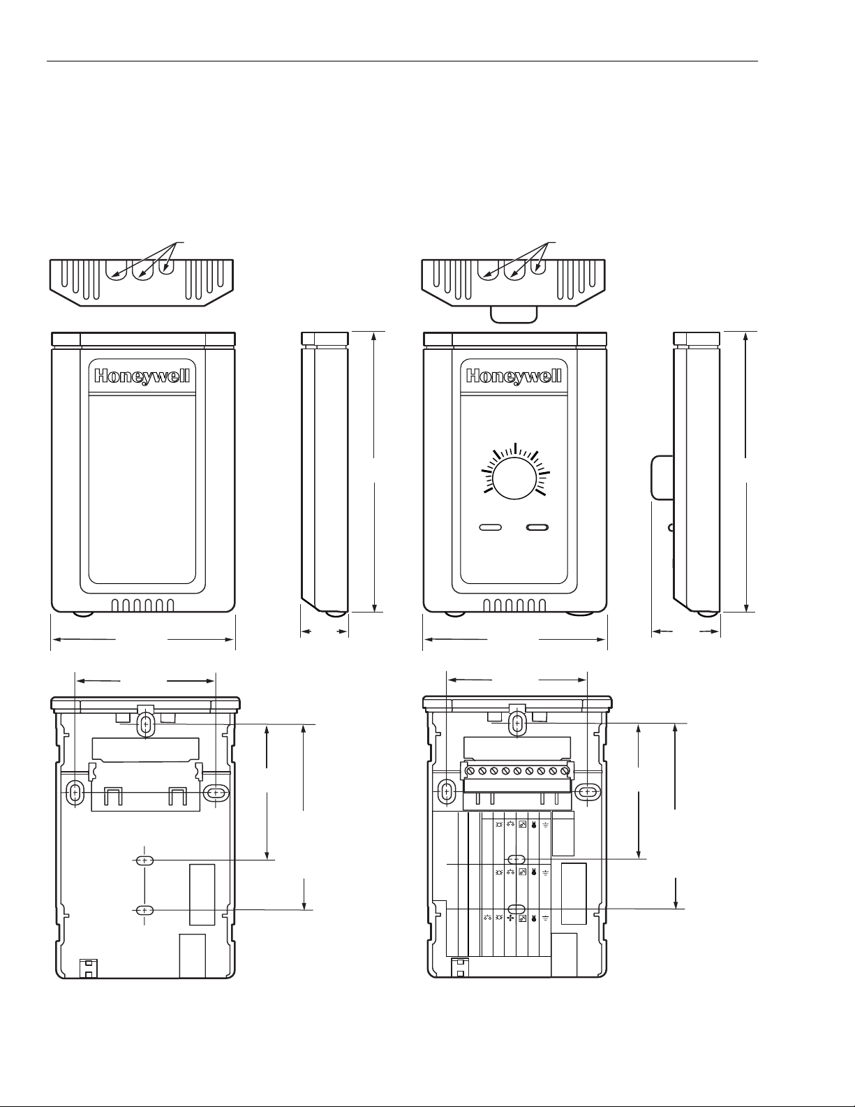
EXCEL 10 W7750A,B,C CONSTANT VOLUME AHU CONTROLLER
y
g
(
g
g
Wall Modules
The T7770 or T7560 Wall Modules for the Excel 5000 and
Excel 10 Controllers ar e available in a variet
urations. The models T7770A1006 and T7770C1002
confi
are shown in Fig. 10. The T7770B,D are the same physical
of
size
T7560A1016 and T7560B1018 are shown in Fi
T7560A,B are the same physical size.
Duct Sensor
The dimensions of the C7770A duct-mounted sensor are
shown in Fi
see Product Names sect ion fo r dif feren ces). The models
. 11. The
. 12.
3-5/32 (80)
KNOCKO UTS F O R EU ROPE AN
APPLICATIONS
29/32
(23)
5-1/16
(128)
60
55
65
70
3-5/32 (80)
KNOCKOUTS FOR EUROPEAN
APPLICATIONS
75
80
85
1-1/4
(32)
5-1/16
(128)
2-3/8 (60)
2-3/8
(60)
T7770A1006
STANDARD
UTILITY
CONDUIT
BOX (2 X 4)
MOUNTING
HOLES
DIP Switch S4 Settings:
2-3/8 (60)
9 8 7 6 5 4 3 2 1
W7752
XL600-XL20
W7753
LED RETURN
1,3,5=on; 2,4=off 2,4=on; 1,3,5=off 1,2,3,4=on; 5=0ff
BYPASS
LED
LED
LED
SETPT
BYPASS/FAN BYPASS/FAN
SETPT
FAN
SETPT
SENSOR
GND
SENSOR
AL COM
SENSOR
GND
E-BUS
E-BUS
T7770C
2-3/8
(60)
Fig. 10. T7770A,B,C,D construction in in. (mm).
74-2958—120
STANDARD
UTILITY
CONDUIT
BOX (2 X 4)
MOUNTING
HOLES
M15119
Page 21
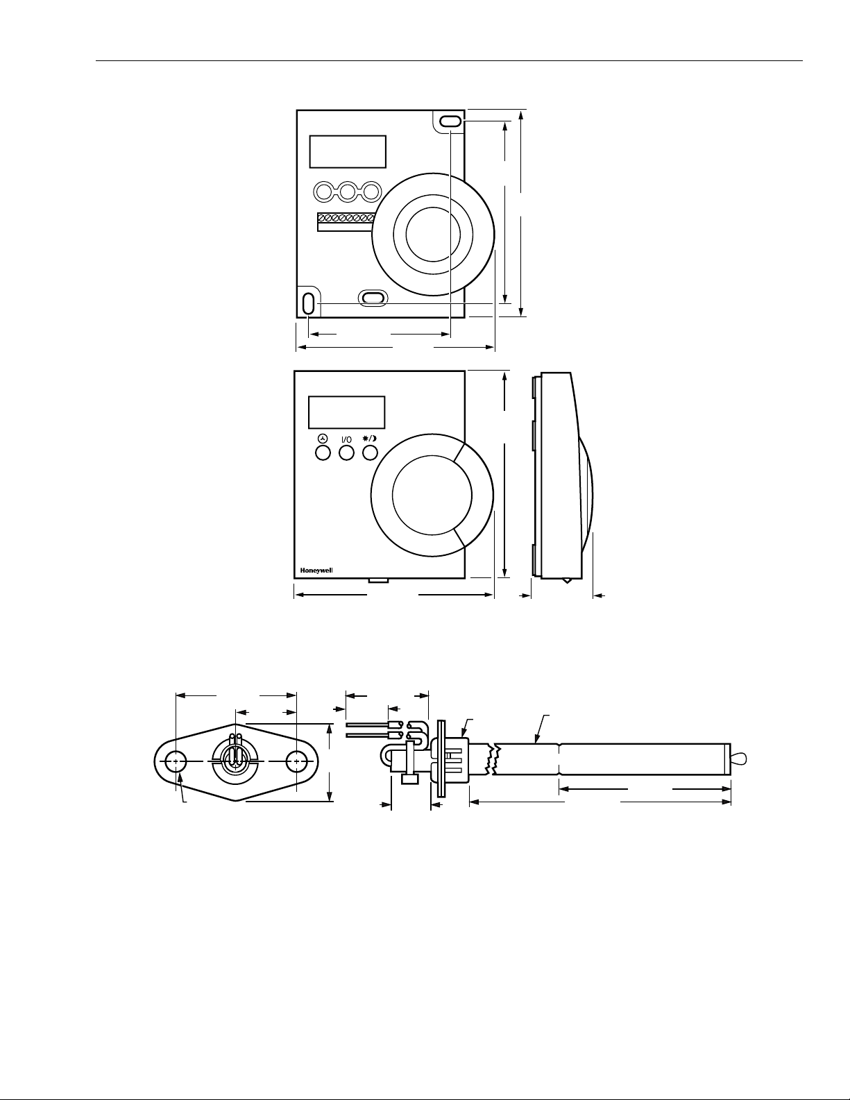
12345678
EXCEL 10 W7750A,B,C CONSTANT VOLUME AHU CONTROLLER
3-7/16
(86)
4
(100)
1-1/2 (38)
3/4 (19)
2-11/16 (68)
3-7/8 (97)
3-15/16 (99)
4-1/8
(104)
1-3/16 (30)
Fig. 11. T7560A,B construction in in. (mm).
8-1/2 (216)
1/2 (13)
1/2 IN. (13)
DIAMETER
3/8 IN. (10)
DIAMETER
M17479
1/4 (6)
DIAMETER (2 HOLES)
7/8
(22)
1/2 (13)
Fig. 12. C7770A construction in in. (mm).
21 74-2958—1
6-5/32 (156)
3-1/2 (89)
M7724
Page 22

EXCEL 10 W7750A,B,C CONSTANT VOLUME AHU CONTROLLER
g
g
g
g
(
y
q
(
y
(
(
(
j
)
y
Configurations
General
Tables 3 and 4 provide an overview of the Excel 10 W7750
uration options. All W7750s are assumed to have a
confi
supply fan digital output. Additionally, Tables 3 and 4 list the
eneral mechanical equipment options available with the
W7750 Controller. See Application Step 6. Confi
Controllers, for further information on configurations.
Table 3. Common Configuration Options Summary For W7750A,B,C Controllers.
Option Possible Configurations Common To All W7750 Models
Supply Fan
Type of Air Handler
Occupancy Sensor
Window Sensor
Wall Module Option
The T77560A,B has no LONW
Wall Module Type
All wall modules have a LONW
ack except T7560A,B
Smoke Emergency Initiation
ORKS
Bus access)2. Network (sensor value received via the LONW
ORKS
Bus access 2. Sensor and Setpoint adjust.
ure
1. Mandator
1. Conventional.
2. Heat Pump.
1. None.
2. Connected: Contacts closed e
3. Network
1. None.
2. Ph
3. Network (Window Open/Closed signal received via the LONW
1. Local
1. Sensor only.
3. Sensor, Setpoint adjust and Bypass.
4. Sensor and Bypass.
1. None.
2. Ph
3. Network (Emergency/Normal signal received via the LONW
Digital Output.
Occ/Unocc signal received via the LONW
sically Connected: Contacts closed equals windo w closed.
direct wired to the controller).
sically Connected: Contacts closed equals smoke detected.
CAUTION
For floating control, the Excel 10 W7750 Controller is
ned to work only with Series 60 valve and
desi
damper actuators. Full strok e actuator dri ve-time mu st
be between 20 and 240 secon ds
uals Occupied.
0.25 to 4.0 m inu tes).
ORKS
Bus network).
ORKS
Bus).
ORKS
ORKS
Bus).
Bus).
74-2958—122
Page 23

Option
g
g
g
g
g
g
g
g
g
g
g
g
g
g
g
g
(
)
)
g
)
g
(
)
(
)
y
(
)
(
)
g
Type of
Heating
Type of
Cooling
Type of
Economizer
IAQ Option
Coil Freeze
Stat Option
Filter Monitor
Option
EXCEL 10 W7750A,B,C CONSTANT VOLUME AHU CONTROLLER
Table 4. Configuration Options Summary For W7750A,B,C Controllers.
Possible Configurations for the
W7750A Model Possible Configurations for the W7750B,C Models
1. One stage. 1. One stage.
2. Two stages. 2. Two stages.
3. Three stages. 3. Three stages.
4. Four sta
es. 4. Four stages.
5. None. 5. Series 60 Modulatin
6. Pulse Width Modulatin
7. None.
1. One sta
2. Two sta
3. Three sta
4. Four sta
e. 1. One stage.
es. 2. Two stages.
es. 3. Three stages.
es. 4. Four stages.
5. None. 5. Series 60 Modulatin
6. Pulse Width Modulatin
7. None.
1. Digital Output Enable/Disable
nal for controlling an external
si
economizer packa
2. Series 60 Modulatin
e.
electric
damper motor, or pneumatic via
ital Output Enable/Disable signal for controlling an external
1. Di
economizer packa
e.
2. Series 60 Modulating electric damper motor, or pneumatic via
transducer.
transducer.
3. None. 3. Pulse Width Modulatin
transducer.
4. None.
1. None. 1. None.
2. Local IAQ Di
ital Input—directly
wired to the controller.
Contacts
2. Local IAQ Digital Input—directly wired to the controller. (Contacts
closed means poor IAQ is detected.
closed means poor IAQ is
detected.
3. Network (IAQ Override signal
received via the LONW
ORKS
Bus).
3. Network (IAQ Override signal received via the LONW
4. Local CO
Analog Input—directly wired to the contro ller . (The sensor
2
must be a 0 to 10V device representin
1. None. 1. None.
2. Local Coil Freeze Stat Di
ital
Input—directly wired to the controller.
2. Local Coil Freeze Stat Digital Input—directly wired to the controller.
Contacts closed means that coil freeze condition is sensed.
Contacts closed means that coil
freeze condition is sense d.
1. None. 1. None.
2. Local Dirty Filter Digital
Input—directl
controller.
wired to the
Contacts closed means
2. Local Dirty Filter Digital Input—directly wired to the controller.
Contacts closed means that the filter is dirty.
that the filter is dirty.
3. Local Analog Input for Differen tial Press ure across the Filter (directly
wired to the controller). The sensor must be a 2 to 10V device
representin
0 to 5 inw (1.25 kPa).
electric va lve, or pneumatic via transducer.
electric valve, or pneumatic via transducer.
electric va lve, or pneumatic via transducer.
electric valve, or pneumatic via transducer.
electric damper motor, or pneumatic via
ORKS
Bus).
0 to 2000 PPM CO2.
23 74-2958—1
Page 24
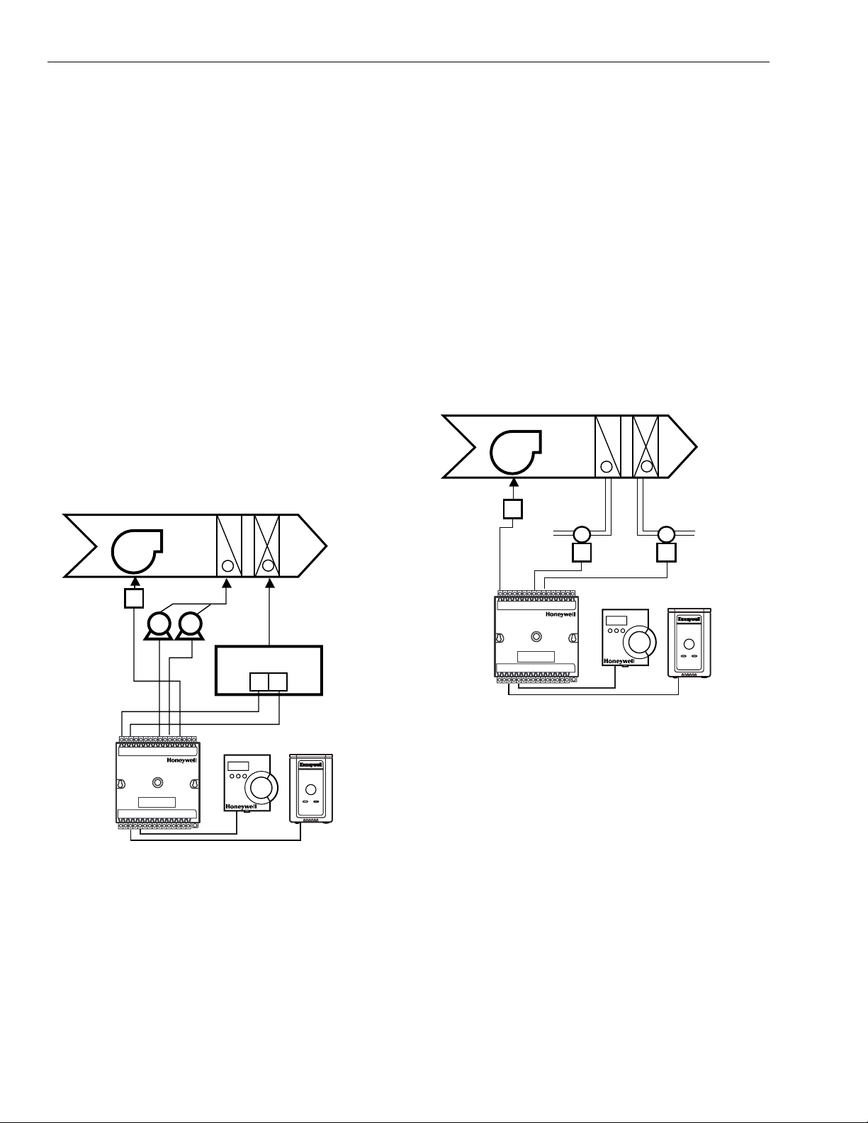
EXCEL 10 W7750A,B,C CONSTANT VOLUME AHU CONTROLLER
g
y
g
g
y
(
y
g
y
y
(
g)
g
g
g eq
g
g
)
g
)
g
g
g
g
g
g
g
g
q
g
g
y
g
y
g
y
g
g
y
y
y
g
y
Allowable Heating and Cooling Equipment Configurations
Each W7750 device can control a variety of different types of
mechanical cooli ng and heating equipment within roof top air
handlers. See Fi
some t
pical configurations. For specific wiring details, see
the Prepare Wiring Diagrams section.
STAGED HEATING/COOLING CONTROL
ed equipment control is available for up to four st ages of
Sta
or four stages of cooling. On the W7750, the stages
heatin
are activated through digital outputs (Triacs on t he W7750B,C
-contact relays on the W7750A) one for each stage
and dr
wired to 24 Vac contactors
Prepare Wiring Diagrams section for wiring details). Note that
the number of ph
limits the total number of sta
example, the W7750A Model has six digital outputs, and
because one is used for the suppl
available for an
with a maximum of four stages of heating and four stages for
coolin
. The W7750B Model offers two additional DOs, for a
total of ei
Outputs (AOs). Fig. 13 shows a typical application of two
es of heat and two stages of cooling.
sta
MIXED
AIR
. 13 through 17 for a conceptual overview of
see Fig. 27 and 30 in Step 4.
sical Digital Outputs (DOs) on the controller
es that can be controlled. For
fan, there are five DOs
combination of heating and cooling stages
ht. The W7750C offers five DOs and three Analog
HEAT
COOL
COIL
COIL
FAN
+
-
DISCHARGE
AIR
positions the actuator based on the len
pulse from the di
ital output. For PWM, the controller outputs
th, in seconds, of the
a pulse whose length consists of two parts, a minimum and a
maximum. The minimum pulse time represents the analo
value of 0 percent and the maximum pulse len
th that
represents an analog value of 100 percent. If th e analog value
reater than 0 percent, an additional time is added to the
is
minimum pulse time. The len
th of time added is directly
proportional to the magnitude of the analog value. The PWM
actuator will be
in to use the analog value at the end of the
pulse and will continue to use this value until a new pulse is
received. Refer to Appendix B under PWM Control for an
example. Series 60 actuators are
than those for PWM, but the trade-off is that PWM re
enerally less expensive
uires
only a single controller digital output while floating control
uses two DOs. Refer to Appendix B under Series 60
Modulatin
Control for an example. Fig. 14 illustrates a
system with modulating heating and cooling (see Fig. 29 and
31 in Step 4. Prepare Wirin
MIXED
AIR
FAN
STARTER
FAN
Diagrams section.
HEAT
COOL
COIL
COIL
-
CHILLED
WATER
VALVE
+
HOT
WATER
VALVE
DISCHARGE
AIR
FAN
STARTER
EXCEL 10
CVAHU
W7750A,B,C
COMPRESSORS
Y1 Y2
GAS COMBUSTION
CONTROLS
W2
W1
T7560A,B OR T7770
M17491
Fig. 13. Fan with two stages of heating and two stages
of cooling.
MODULATING HEATING/COOLING CONTROL
The W7750 Controller p rovide s mod ulatin
for heatin
see Fi
and cooling equipment (and economizer damp ers,
. 16) using either Series 60 Floating Control or P ulse
uipment control
Width Modulated (PWM) control, (PWM control is avail able on
only
the W7750B,C
provided throu
. The Series 60 Modulating Control is
h two Relay digital outputs on the W7750A or
two Triac digital outputs on the W7750B,C (one to pulse the
valve actuator open and one to pulse it closed
. PWM control
EXCEL 10
CVAHU
W7750A,B,C
T7560A,B OR T7770
M17492
Fig. 14. Fan, modulating heating and modulating cooling.
NOTE: Pneumaticall
a pneumatic transducer device. See Fig. 17.
usin
actuated valves can be controlled
Also, transducer devices are available from third
vendors to convert PWM outputs to a voltage
part
or current si
nal if desired.
HEAT PUMP CONTROL
The W7750 Controller handles heat pump applications
similarly to staged heating/cooling control. Heat pump
applications are supported b
compressor sta
es, a change-over relay for the refrigerant
providing outputs for up to four
reversing valve, and up to four stages of auxiliary heat. Note
that the W7750A Model has six di
with one DO used for the suppl
over rela
, there are four outputs available for any
combination of compressors and auxiliar
W7750B Model offers two additional DOs for a total of ei
ital outputs, and therefore,
fan and one for the change-
heat stages. The
ht,
while the W7750C Model offers five DOs and 3 AOs. Fig. 15
illustrates a t
pical heat pump system with auxiliary heat.
74-2958—124
Page 25
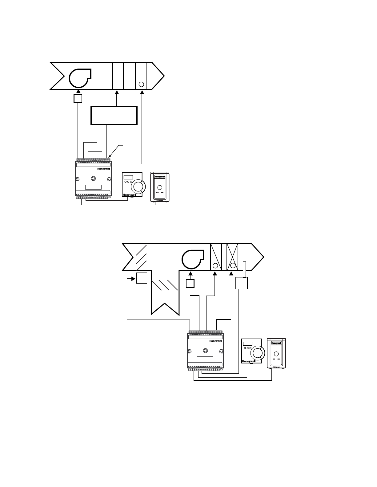
EXCEL 10 W7750A,B,C CONSTANT VOLUME AHU CONTROLLER
g
g
g
g
)
q
y
y
g
g
q
y
g
g
q
g
j
g
AUXILIARY
HEAT
STAGE(S)
+
RELAY
T7560A,B OR T7770
DISCHARGE
AIR
M17493
MIXED
AIR
EXCEL 10
CVAHU
W7750A,B,C
FAN
FAN
STARTER
COMP 1
COMP 2
SHARED
HEAT AND
COOL COIL
COMPRESSOR AND
CHANGEOVER V ALVE
CHANGEOVER
Fig. 15. Heat pump with two compressors and auxiliary
heat stage(s).
ECONOMIZER CONTROL
Economizer control is available concurrently with any
uration i n the W7750 when DOs are not all used by the
confi
and cooling equipment. Two types of economizer
heatin
controls are supported by the W7750 Controller, modulating
control and enable/disable control. Modulatin
either Series 60 Floatin
control is available on the W7750B,C
temperature sensor is re
Control or PWM control (PWM
only
uired for modulating economizer
control can be
. A discharge air
damper control. Enable/dis ab le c ontrol is provided to emulate
the Hone
where a DO tracks the occupanc
external packa
well T7300 thermostat economizer operation,
status of the controller. An
ed economizer control then modulates the
dampers. For modulating control, the economizer is enabled
or disabled based on one of ten available strate
Appendix B—Se
uences of Operation—Economizer Enable/
ies (see
Disable Control section, for further details). Fig. 16 illustrates
stem with modulating economizer dampers (see Fig. 29,
a s
31, 32 and 35 in Step 4 . Prepa re Wiri n
Diagrams section, for
wiring details).
OUTDOOR
AIR
M
PWM OR
SERIES 60
FLOATING
MOTOR
RETURN
AIR
EXCEL 10
W7750A,B,C
CVAHU
Fig. 16. Economizer control.
PNEUMATIC ACTUATOR CONTROL
The W7750B,C Controll er can contr ol pneumat ic actuato rs for
any or all of the three modulating outputs provided by the
control algorithm (heat, cool and economizer). Control of
pneumatic water/steam valves and damper actuators is
provided throu
h a transducer device using either Series 60
Floating Control or PWM DOs. A floating-to-pneumatic, or a
PWM-to-pneumatic transducer is re
nal. The W7750A Controller can drive Series 60 Floating
si
uired for each output
HEAT
COOL
COIL
COIL
FAN
FAN
STARTER
+
-
T7560A,B OR T7770
DISCHARGE
AIR
DISCHARGE
TEMPERATURE
SENSOR REQUIRED
FOR ECONOMIZER
CONTROL
M17494
Control to modulate cooling valves, heating valves and
economizers. There are no PWM outputs configurable on the
W7750A model.
For pro
ects with existing pneumatically actuated reheat
valves, the Excel 10 W7750 Controller output must be
converted to a pneumatic si
nal using a transducer device
developed for use with Excel 10 C ontrollers. The tran sducer is
25 74-2958—1
Page 26
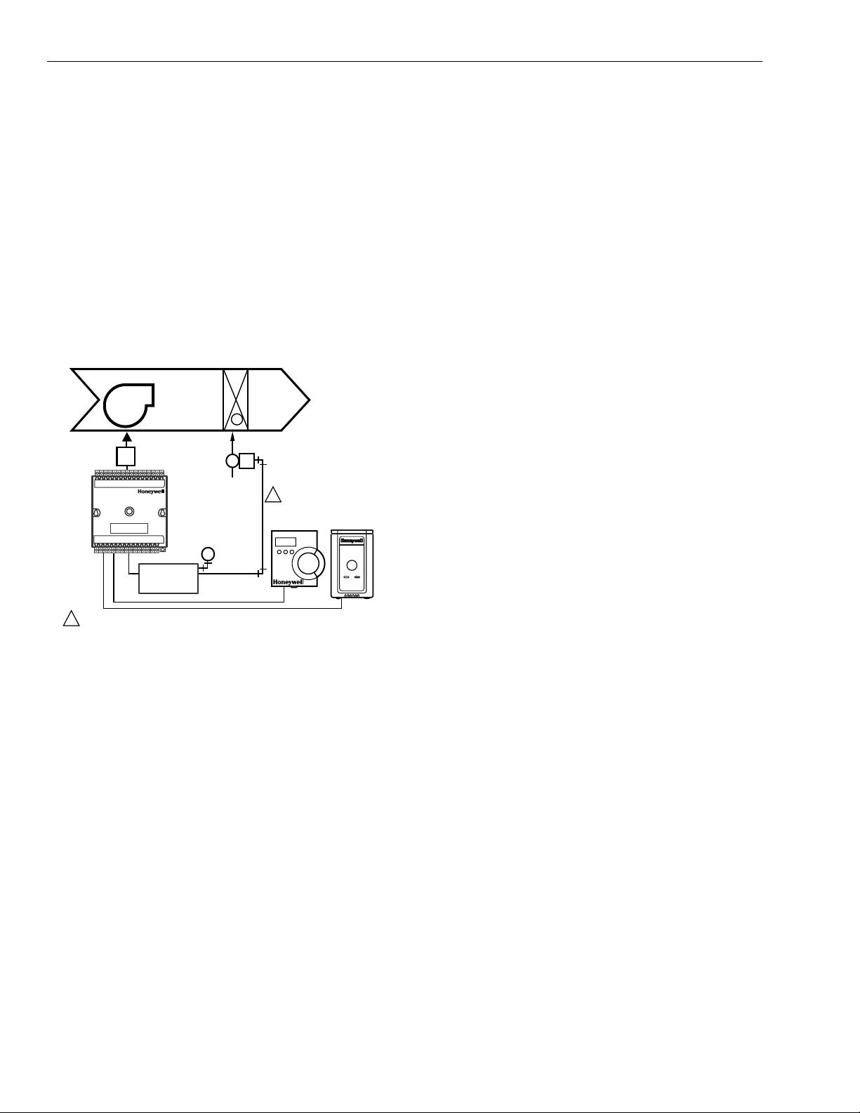
EXCEL 10 W7750A,B,C CONSTANT VOLUME AHU CONTROLLER
y
g
g
g
g
g
g
y
g
g
y
y
(
g
g
y
y (
y (
y
y
y
g
y
y
y
(
gh q
y
)
g
g
y
y
q
g
g
g
y
g
g
g
(
(
)
(
y
gh q
y
(
)
g
g
(
g
g
available through Honeywell, or directly from the
manufacturer, Mamac S
stems (see Table 11 for ordering
information).
Fi
. 17 depicts a typical W775 0 System with modulating
heating valve using a pneumatic valve actuator. Also see Fig.
36 for wirin
W7750A,B,C Controller and Fi
an MMC325 Pneumatic Transducer to a
. 37 for wiring a RP7517B
Pneumatic Transducer to a W7750C Controller.
NOTE: When choo sin
the pneumatic pressure ra nge, make
sure that the close-off pressure is 2 to 3 psi greater
than that of the sprin
e of 5 to 10 psi with 10 psi as the closed posi-
ran
do not
tion,
use the 0 to 10 psi model of the MMC325
range. When using a spring
Transducer; use the 0 to 20 psi transducer as the
recommended selection.
HEAT
COIL
MIXED
AIR
STARTER
1
FAN
+
FAN
MMC325
PNEUMATIC MAIN OR BRANCH LINE MUST BE 1/4 IN. (6 MM)
OR LARGER TUBING. A MINIMUM OF 6 FT (1.8M) OF TUBING
IS NEEDED IN A BRANCH LINE.
PNEUMATIC
ACTUATOR
VALVE
M
PNEUMATIC
TRANSDUCER
1
DISCHARGE
AIR
T7560A,B OR T7770
M17495
Fig. 17. Modulating heat with pneumatic valve actuator.
MIXED-OUTPUT-TYPE CONTROL
The W7750B,C Controller provides control for mixed-output-
pes of applications such as PWM heating and staged
t
control occurring simultaneously with Series 60
coolin
Floatin
Economizer Damper Control.
Occupancy Sensor
Excel 10 W7750 Controllers provide a digital input for
connection to an occupanc
a passive inf rared m oti on de tec tor, that contains a dr
see following NOTE) closure to indicate whether or not
people are present in the space. The Excel 10 W7750
Controller expects a contact closure to indicate the space is
Occupied. See Fi
. 27 through 35 in Application Step 4,
Prepare Wiring Diagrams, for details on wiring connections.
The control al
occupanc
Occupanc
TOD) schedule indicates an Occupied state, and the
Da
occupanc
orithm in the Excel 10 Controller uses the
sensor, if configured, to determine the Effective
see Table 5) mode of operation. If the Time Of
sensor contact is closed, the Effective Occupancy
mode is Occupied. However, if the TOD schedu le indica tes an
Occupied state and the occupanc
sensor. This is a device, such as
contact
sensor contact is open,
then the Effective Occupanc
temperature control al
mode is STANDBY. The
orithm is then controlled to the
STA NDBY Cooling and Heating Setpoints.
If the occupanc
sensor is not configured, a local controller
can be put in th e STANDBY mode only by either a one-to-one
association of the occupanc
Controller to the local c ontroller, or b
mode signal via the LONW
sensor from another Excel 10
receiving the ST ANDBY
ORKS
Bus.
NOTE: The Excel 10 Controller has limited power available
only 9 mA at 4.8 volts) for checking the digital inputs
for contact closures. It is very important that the
device used contains hi
contacts with resistivit
uality, noncorroding
that does not degrade; that
is, increase over tim e. Use nobl e metal (such as gold
or silver
consistent, lon
, or pimpled or sealed contacts to assure
-term operation.
The recommended devices for use with the Excel 10 W7750
Controllers are the EL7628 A1007 C eilin
Mounted Infrared or
the EL7680A1008 Wall Mounted Wide View Infrared
Occupanc
EL761 1A1003 and the EL7612A10 01 Occupanc
Sensors. If ultrasonic sensors are required, the
Sensors are
recommended. An EL76XX Power Supply/Control Unit is
uired for use with these occupancy sensors. Th e
re
EL7630A1003 can power up to four sensors, and is multitapped for several line volta
power three sensors and it connects to 120 Vac line volta
es. The EL7621A1002 can
e.
The EL7621A1010 can also power three sensors but it
connects to 277 Vac line volta
e.
Window Open/Closed Digital Input
A digital input is also provided for detec ting whether a window
in the space was o pen ed. Th e Exc el 10 W775 0 Contro ller c an
be connected to a dr
contact (see the following NOTE and
Fig. 27 through 35 in Application Step 4. Prepare Wiring
rams, for details) or a set of contacts wired in series (for
Dia
monitorin
multiple win dows) to verify that the window(s) are
closed. The algorithm expects a contact closure to indicate
the window is closed. If an open window is detected, the
orithm changes the mode of operation to
al
FREEZE_PROTECT, which shuts down the control functions,
and watches for low space temperature conditions. The frost
protection setpoint is 46 .4°F
8°C), and the frost alarm occurs
at 42.8°F (6°C).
NOTE:
This is the same NOTE as in the Occupancy Sensor
section.
The Excel 10 has limited power available
only 9 mA at 4.8 volts) for checking the digital inputs
for contact closures. It is ver
device used contains hi
contacts with resistivit
is, increase over tim e. Use nobl e metal
or silver
consistent, lon
, or pimpled or sealed contacts to assure
-term operation.
important that the
uality, noncorroding
that does not degrade; that
such as gold
Wall Module Options
As previously discussed, there are four basic varieties of the
T7770 Wall Mod ules and two of the T7560 Di
see the Product Names and the C onstructi on section s). Also,
a T7770 and T7560 Wall Modules can be shared among two
or more W7750s. The control al
wall module information when confi
orithm must be given this
uring the W7750 (see
Excel E-Vision User’s Guide, form 74-2588).
ital Wall Module
74-2958—126
Page 27

EXCEL 10 W7750A,B,C CONSTANT VOLUME AHU CONTROLLER
g
g
(
)
(
y
q
g
q
y
g
)
g
)
g
g
g
g
(
q
g
q
y
g
y
g
y
(
g
g
y
y (
g
g
y
y
y
y)
g
y
(
g
Dirty Filter Monitor
The air filter in the a ir han dler c an be mon itored by the W7750
and an alarm is issued when the filter media needs
replacement. The two methods of monitorin
1.
Connecting a differential pressure switch to a digital
input on the W7750A or W7750B,C.
2.
a 2 to 10V differential pressure sensor to a
Wirin
voltage input on the W7750B,C. If the analog input
sensor is used, its measu red valu e 0 to 5 inw
is compared to a user-selectable setpoint
kPa
FltrPressStPt—valid range: 0 to 5 inw (0 to 1.25 kPa)),
and the Dirt
drop across the filter exceeds the setpoint.
Filter alarm is issued when the pressure
the filter are:
0 to 1.25
Indoor Air Quality (IAQ) Override
The Excel 10 W7750 Controller provides IAQ ventilation
control using one of two different methods of detecting poor
uality. The first is with an IAQ switch device connected to
air
ital input on the W7750 Controller, where a contact
a di
closure indicates poor air quality, and initiates the IAQ
Override mode. The device can detect poor air
desired measure such as CO2, VOC, CO, etc. The
an
second method, which is only available on the W7750B,C, is
h an analog input that connects to a CO2 sensor (2 to
throu
. The measured value of C O2 from this sensor (0 to 2000
10V
PPM) is compared to the setpoint (IAQSetpt). When the CO2
level is hi
her than the setpoint (800 PPM
uality using
adjustable
, the
IAQ Override is initiated. The IAQSetpt hysteresis is 50 PPM,
IAQ Override is deactivated at a CO
below setpoint.
The effect of initiatin
economizer dampers are allowed to open above the standard
minimum position settin
buildin
further control details.
. See Appendix B—Sequences of Operation, for
the IAQ Override mode is that the
to allow more fresh air to enter the
level less than 50 PPM
2
Smoke Control
The Excel 10 W7750 Controller supports smoke-related
control strate
command
connected) smoke detect or digital input. The details of the
W7750 smoke-related control ope rati on are des cri bed in
Appendix B—Se
ies that are initiated either via a network
DestEmergCmd) or from a local (physically
uences of Operation.
Freeze Stat
A freeze stat can be monitored by the W7750 and issue a
freeze stat alarm indicating the CVAHU is in danger of
freezin
control operation are de scribed i n Appendix B—Se
Operation.
its coil. The details of the W7750 freeze stat related
uences of
Modes of Operation
The possible modes of operati on fo r t he W7 750 Co ntrolle r are
listed in Table 5.
Table 5. Modes Of Operation For The Excel 10 W7750 Controller .
Mode Description Events causing a controller to switch to this mode
Effective Occupancy (User Address: StatusOcc)
OCCUPIED
STANDBY
UNOCCUPIED
BYPASS
OCCUPIED
Override Modes (User Address: StatusOvrd)
OCCUPIED
STANDBY
Controlle r is in Occupied mode Any of the following: Network input (DestSchedOcc) containing a
Controller is in Standb
Controller is in Unoccupied mode Network input
Controller is in Occup ied mo de t hrou
pass command
a B
Controller occupancy mode was
overridden to Occupied mode
Controller occupancy mode was
overridden to Standb
mode Either: (A) Network input (DestSchedOcc) containing a time-of-day
mode
time-of-da
ONWORKS
L
from Network input (DestManMode) for manual override to OCC m ode.
DestManMode has the hi
and then DestSchedOcc.
schedule fla
Bus node is STANDBY, or (B) Network input (DestSchedOcc) is
OCCUPIED and the Occupanc
from the Excel 10 Zone Mana
input DestManOcc has a value of UNOCCUPIED.
This mode is derived from the schedule occupanc
h
havin
from one of three sources. Two of these are si
to the unit, and received b
source for an occupanc
a wall module. These three sources are arbitrated in a scheme
determined b
Wins from OvrdPriorit
Network input (DestManOcc) containing a time-of-day schedule
override si
other L
Network input
override si
LONW
schedule flag from either the Excel 10 Zone Manager or an
Bus Controller; Time Clock DI, Occupancy Sensor DI; or
hest priority, followed by the Time Clock DI,
from the Excel 10 Zone Manager or other LONW
Sensor DI is UNOCCUPIED.
DestSchedOcc) containing a time-of-day schedule flag
a state of UNOCCUPIED and a manual request for occupancy
the configuration parameter (Network Wins or Last-in
nal of OCCUPIED from the Excel 10 Zone Manager or
ONWORKS
ORKS
Bus device.
DestManOcc) containing a time-of-day schedule
nal of STANDBY from the Excel 10 Zone Manager or other
Bus device.
er or LONW
DestManOcc and DestBypass. The third
request is from an override button located on
.
ORKS
Bus, or the network
nals originated external
ORKS
DestSchedOcc)
27 74-2958—1
Page 28

EXCEL 10 W7750A,B,C CONSTANT VOLUME AHU CONTROLLER
y
y
g
y
y
gg
y
g
g
(
g
(
y
y
(
(
y
g
g
y
g
(
(
g
y
g
(
Table 5. Modes Of Operation For The Excel 10 W7750 Controller (Continued).
Mode Description Events causing a controller to switch to this mode
UNOCCUPIED
BYPASS
Controller occupancy mode was
overridden to Unoccupied mode
Controller occupanc
mode was
overridden to Bypass the current
Network input (DestManOcc) containing a time-of-day schedule
override si
other LONW
nal of UNOCCUPIED from the Excel 10 Zone Manager or
ORKS
Bus device.
DI (Bypass) was pressed, and the Bypass duration timer has not yet
expired, or the network input DestManOcc has a value of BYPASS.
Unoccupied mode
NOT
pass action No Override input receiv ed.
No B
ASSIGNED
Operational Modes (User Address : StatusM ode)
START-UP
AND WAIT
COOLING
HEATING
EMERGENCY
HEAT
On power-up, provides a st a
ered
start sequence to evenly apply the load
to the electrical s
The Excel 10 is controllin
stem.
the Cooling
mode.
The Excel 10 is controllin
the Heating
mode.
Compressors are disabled and onl
Auxiliar
Heat stages are allowed to
This mode occurs on con troller powe r-up, an d afte r downl oadin
controller from the configuration tool. Temperature control loops are
disabled.
Space temperature h as ris en abov e the c urrent coo ling setpoint, or the
network input
DestHvacMode) is COOL.
Space temperature has fa llen below the curren t heating setpoint, or the
network input
The network input
DestHvacMode) is HEAT.
DestManHvacMode) is EMERG_HEAT.
operate.
OFF MODE
The heat/cool control is turned off
immediately. The node is not running its
Network input
DestManMode) containing AHU operational mode
information from C-Bus has value of MORNING WARM-UP.
normal temperature control.
DISABLED
MODE
The heat/cool control and frost
protection are turned off immediatel
The node is not runnin
its normal
–
.
temperatur e control.
SMOKE
EMERGENCY
The node has entered a smoke
ency. The fan and dampers are
emer
Network input
another L
DestEmergCmd) containing smoke control signal from
ONWORKS
Bus device has value of SMOKE_EMERG.
then set to the conditions configured by
SmkCtlMode. The control remains in
SMOKE_ EMERGENCY until power is
cled or the node receives
c
DestEmer
Cmd set to
EMERG_NORMAL.
FREEZE
PROTECT
MANUAL
POSITION
The temperature contr ol i s set to H EAT
with the setpoint set to the frost limit
setpoint 46.4°F
The ph
sical outputs are being
8°C).
controlled manually. The temperature
The Window di
ital input detects an open window.
Typically this is done by the user through E-Vision or XBS by setting
the point DestManMode to MANUAL mode.
control loop is turned off.
FAN ONLY
DISABLED
Control al
that the fan is turned on.
Control algorithm is shut off. Network input (DestManMode) containing AHU operational mode
orithm is disabled, except
The space temperature sensor has failed, or the network input
DestHvacMode) is FAN ON LY.
information from an operator or the network that has a value of
DISABLED.
to the
NOTE: During all modes all digital and analog physical
inputs are periodicall
read, the diagnostic output
network variables can be polled, the input network
variables are received, and the output network
variables are sent periodicall
74-2958—128
.
Page 29
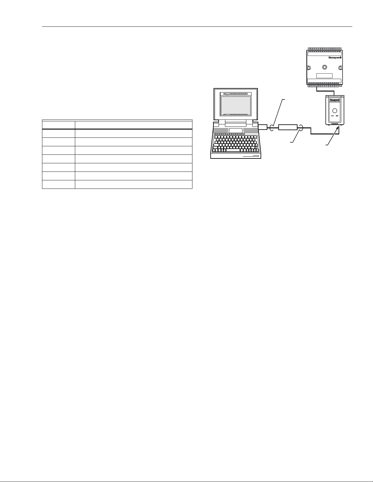
g
g
g
g
q
q
g
g
y
y
y
(
y
g
g
(
q
y
g
(
g
g, (
gy
g
gy
g
g
g
(
y
(s)
(s)
g
g
y
j
g
g.)
y
)
g
g
g
y
g
y
q
y
g
q
g
g
M15120A
NOTEBOOK PC
LONWORKS BUS
PORT
EIA-232
SERIAL
PORT
Q7752A
SLTA
CABLE
PART
NO. 205979
SHIELDED
INTERFACE
CABLE
EXCEL 10
W7750
CVAHU
CONTROLLER
EXCEL 10 W7750A,B,C CONSTANT VOLUME AHU CONTROLLER
APPLICATION STEPS
Overview
The seven application steps shown in Table 6 are planning
considerations for en
These steps are guidelines intended to aid understanding of
the product I/O options, bus arran
uration options and the Excel 10 W7750 Co ntro lle r role
confi
in the overall EXCEL 5000 OPEN SYSTEM architecture.
Step No. Description
1 Plan The S
2 Determine Other Bus Devices Re
3La
4 Prepare Wiring Diagrams
5Order E
6Confi
7 Troubleshootin
Step 1. Plan the System
Plan the use of the W7750 Controllers according to the job
requirements. Determine the location, functiona lity and sensor
or actuato r usa
W7750 Controllers, T7770 and T7560 Wall Modules re
for each model type. Also check the number and type of
output actuators and o ther re
When plannin
expansion possibilities to allow for future
important to be prepared for adding HVAC systems and
ver
controllers in future projects.
T7560 Wall Modules can onl
ORKS
LONW
as either hard-wired I/O-onl
be run to them
CARE/E-Vision operator terminal to have access to the
ONWORKS
L
how man
T7770 Wall Modules, except the T7770A1006 and the
T7770A1014, can be connected via the L
Also the app lication en
T7770s without L
bein
wall modules
re
uired during installation to ensure that the proper number
and t
buildin
to the LONW
terminal
Wirin
differences between the two types.
Bus access. T7770 Wall Modules can be in sta ll ed
Bus. The applicat ion engineer needs to dete rmine
wall modules, T7770s and T7560s ar e required. All
installed on the job, and then clearly document which
if any) have network access . This informati on is
pe of wires are pulled to the wall modules, and the
operators are informed about where they can plug in
ORKS
see Fig. 18, 19 and 20). Refer to Step 4. Prepare
Diagrams for details, about the about the wiring
ineering an Excel 10 W7750 System.
ement choices,
Table 6. Application Steps.
stem
uired
Out Communications and Power Wirin
uipment
ure Controllers
e. Verify the sales estimate of the number of
uired
uired accessories.
the system layout, consider potential
rowth. Planning is
be hard-wired, they have no
devices or additional wiring can
for the LONW
ORKS
Bus network) to allow a
ONWORKS
Bus jack.
ineer needs to know how many
ONWORKS
Bus network connections are
Bus network with a portable operator
Fig. 18. Connecting the portable operator terminal
to the LONW
The FTT communication wirin
controllers is a free topo lo
loop, and mixed wirin
architecture. Refer to the LONW
scheme that support s T-tap, star,
ORKS
LONW
® Bus.
ORKS
Bus) between
ORKS
Bus Wiring Guidelines form, 74-28 65 for compl ete descri ption
of network topolo
Communications and Power Wirin
rules. See Application Step 3. Lay Out
, for more information on
bus wiring layout, and see Fig. 27 through 35 in Appl ication
Step 4. Prepare Wirin
The application en
Control
DDC) job requirements. This includes the Sequences
of Operation for the W7750 units, and for the s
Diagrams, for wiring details.
ineer must review the Direct Digital
stem as a
whole. Usually there are variables that must be passed
between the W7750 Controllers and other zone controller
or central plant controller
that are required for optimum
system-wide operation. Typical examples are the TOD Occ/
Unocc si
control si
It is important to understand these interrelationships earl
the
confi
nal, the outdoor air temperature, the demand limit
nal, and the smoke control mode signal.
in
ob engineering process to ensure implemention when
uring the controllers. (See Application Step 6. Configure
Controllers, for information on the various Excel 10
parameters and on Excel 10 point mappin
Step 2. Determine Other Bus Devices Required
A maximum of 62 nodes can communicate on a single
ONWORKS
L
constitutes one nod e. If more nodes are required, a Q7751A,B
Router is necessar
divided between two L
accounts for two o f these nodes (one node on each side of the
router
and two nodes are available for operator terminal nodes,
leavin
controllers are able to talk to each other throu
Q7750A Excel 10 Zone Mana
LONW
stem C-Bus. Each Excel 10 Zone Manager supports up to
S
120 Excel 10 Contr ollers. This limit is se t in the Excel 10 Zon e
Mana
Bus segment. Each W7750 (CVAHU) Controller
. Using a router allows up to 125 nodes,
ONWORKS
Bus segments. The router
; a Q7750A Excel 10 Zone Manager takes one node
120 nodes available for Excel 10 Controllers. All 120
h the router. A
er is required to connect the
ORKS
Bus to the standard EXCEL 5000 OPEN
er database as an absolute maximum.
,
29 74-2958—1
Page 30

EXCEL 10 W7750A,B,C CONSTANT VOLUME AHU CONTROLLER
gy
g
g
y
g
g
gly
y
y
(
g
(
)
)
(
)
(
y
gy
g
g
g
(
g
g
(
(
)
g
(
g
(
)
)
)
g
Each LONW
ORKS
Bus segment is set up with two unused
nodes to allow for a CARE/E-Vision operator terminal to be
connected to the L
One L
ONWORKS
ONWORKS
Bus. Multiple CARE/E-Vision
Table 7. L
ONWORKS
Bus Segment Example Maximum Number of Nodes Equals 62
® Bus Configuration Rules And Device Node Numbers.
One Q7750A Excel 10 Zone Mana
Port for operator terminal access
CARE/E-Vision)1 node
Maximum number of Excel 10s 60 node s
Total62 nodes
Two L
ONWORKS
Bus Segments Example Maximum Number of Nodes Equals 125
One Q7750A Excel 10 Zone Mana
One Q7751A,B Router 2 nodes
Ports for operator terminal access (two CARE/E-Vision
terminals
Maximum number of Excel 10s in segment number one 60 nodes
Maximum number of Excel 10s in se
ment number two 60 nodes
Total
Refer to the LONW
for complete description of network topolo
maximum wire len
ORKS
Bus Wiring Guidelines form, 74-2865
rules and the
th limitations. If l onger runs are required, a
Q7740A 2-Way or Q7740B 4-Way Repeater can be added to
extend the len
th of the LONW
can be added to partition the s
effectively double the length of the LONW
router is allowed with eac h Excel 10 Zo ne Mana
network se
In addition, all L
ment can have a maximum of one repeater.
ONWORKS
installation of a 209541B Termination Module for a sin
terminated LONW
Modules for a doubl
details on L
ORKS
ONWORKS
Bus or two 209541B Termination
terminated LONW
Bus termination, refer to th e LONW
ORKS
Bus. A Q7751A,B Router
stem into two segments and
ORKS
Bus. Only one
er, and each
Bus segments require the
ORKS
Bus. For more
ORKS
Bus Wiring Guidelines form, 7 4-28 65, or s ee Appl ic ati on Step
Out Communic ations and Power Wiring, and the
3. La
ONWORKS
L
Bus Termination Module subs ectio n in App licat ion
Step 4.
Step 3. Lay Out Communications and Power Wiring
LONW
The communicatio ns bus , LONW
second
differential Manchester encodin
ONWORKS
L
0.34 mm
Bus Layout
®
ORKS
ORKS
Bus, is a 78- kil ob its p er
kbps) serial link that uses transformer isolation and
. Approved cable types for
Bus communications wiring is Level IV 22 AWG
2
plenum or non-plenum rated unshielded, twisted
terminals can be connected to the L
same time. Table 7 summarizes the L
ONWORKS
ONWORKS
Bus at the
Bus segment
configuration rules.
er 1 node
er 1 node
1 in each Bus Segment
2 nodes (1 in each Bus Segment
125
nodes
pair, so lid con duc tor wire. For nonplenum areas, use Level IV
22 AWG (0.325 mm
U.S. part AK3782
rated Level IV, 22 AWG (0.325 mm
AK3791
one pair) or U.S. part AK3792 (two pair). See Tables
2
, such as U.S. part AK3781 (one pair) or
two pair). In plenum areas, use plenum-
2
such as U.S. part
9 and 11 for part numbers. Contact Echelon Corp. Technical
Support for the recommended vendors of Echelon approved
cables. Th e FTT communications bus, L
supports a polarit
insensitive, free topology wiring scheme
ONWORKS
that supports T-tap, star, loop, and mixed bus wiring.
ONWORKS
L
ways, so refer to the LONW
Bus networks can be configured in a variety of
ORKS
Bus Wiring Guidelines form,
74-2865 for complete description of network topolo
and Table 7. Fi
. 19 and 20 depic t t w o typical LONW
network topologies; One has only one doubly terminated
ONWORKS
L
showin
Bus segment that has 60 nodes or less, and one
two singly terminated LONW
ORKS
Bus segments that
has 120 nodes or less (60 MAX per each segment). The bus
uration is set up using the Network Manager tool from
confi
within CARE
see the CARE Excel 10 Zone Manager User’s
Guide, form 74-1392).
NOTE: For wirin
details see the LONW
ORKS
Bus
Termination Module subsection in Step 4. For wall
module wirin
U.S. part AK3792
ONWORKS
L
, U.S. part AK3782 (non-plenum) or
plenum) can be used. For a
Bus that is a doubly terminated daisychain, these cables co ntain two twisted pairs
the run down to the wall module, and one for the run
back up to the controller
for ease of installation.
Bus,
rules
ORKS
Bus
one for
74-2958—130
Page 31

T7770
EXCEL 10
VAV
EXCEL 10
CVAHU
EXCEL 10 W7750A,B,C CONSTANT VOLUME AHU CONTROLLER
209541B
TERMINATION MODULES
(AT ENDS OF
ONWORKS BUS
L
DAISY-CHAIN)
ONWORKS BUS
L
EXCEL 10
CVAHU
EXCEL 10
Q7750A
ZONE
MANAGER
TO C-BUS
(SEE FIG. 1)
UP TO 60
TOTAL NODES
T7770
EXCEL 10
VAV
T7770
EXCEL 10
CVAHU
JACK FOR
OPERATOR
TERMINAL
LONWORKS BUS
EXCEL 10
VAV
T7770
L
ONWORKS BUS
T7770 OR T7560A,B
EXCEL 10
CVAHU
EXCEL 10
VAV
EXCEL 10
VAV
Fig. 19. Wiring layout for one doubly terminated daisy-chain LONW
EXCEL 10
CVAHU
® Bus segment.
ORKS
LONWORKS BUS
I/O CONNECTIONS
T7770s
WITH
NO
L
ONWORKS BUS
ACCESS
M17496
31 74-2958—1
Page 32

EXCEL 10 W7750A,B,C CONSTANT VOLUME AHU CONTROLLER
g
q
g
y
q
g
g
q
g
g
g
g
)
y
y
y
y
)
g
ONWORKS BUS
L
SEGMENT NUMBER 1
T7770
EXCEL 10
VAV
ONWORKS
L
BUS
ACCESS
ONWORKS BUS
L
SEGMENT NUMBER 2
EXCEL 10
Q7750A
ZONE
MANAGER
EXCEL 10
CVAHU
EXCEL 10
VAV
TO C-BUS
(SEE FIG. 1)
EXCEL 10
CVAHU
EXCEL 10
CVAHU
209541B
TERMINATION
MODULE
EXCEL 10
VAV
L
ONWORKS BUS
SEGMENT NUMBER 2
T7560A,B
Q7751A
FTT
L
BUS
ROUTER
Fig. 20. Wiring layout for two singly terminated
L
NOTE: See the L
for wirin
ONWORKS
ONWORKS
details.
® Bus segments.
Bus Termination Module s ect ion
IMPORTANT
Notes on communications wiring:
• All field wiring must conform to local codes and ordinances or as specified on installation wiring diagrams.
• Approved cable types for L
ONWORKS
Bus communications wiring is Level IV 22 AWG (0.34 mm2) plenum or non-plenum rated unshielded, twisted pair,
solid conductor wire. For nonplenum areas, use
Level IV 22 AWG (0.34 mm
2
), such as U.S. part
AK3781 (one pair) or U.S. part AK3 782 (two pai r). In
plenum areas, use plenum-rated Level IV, 22 AWG
(0.34 mm
2
) such as U.S. part AK3791 (one pair) or
U.S. part AK3792 (two pair). See Tables 9 and 11 for
part numbers. Contact Echelo n Corp. Technical Support for the recommended vendors of Echelon
approved cables.
• Unswitched 24 Vac power wiring can be run in the
same conduit as the L
ONWORKS
Bus cable.
EXCEL 10
CVAHU
209541B
TERMINATION
MODULE
ONWORKS
EXCEL 10
CVAHU
• Do not use different wire types or gauges on the
same L
ONWORKS
Bus segment. The step change in
line impedance characteristics causes unpredicta bl e
reflections on the bus. When using different types is
unavoidable, use a Q7751A,B Router at the junction.
• In noisy (high EMI) environments, avoid wire runs
parallel to noisy power cables, or lines containing
lighting dimmer switches, and keep at least 3 in.
(76 mm) of separation between noisy lines and the
ONWORKS
L
• Make sure that neither of the L
Bus cable.
ONWORKS
Bus wires
is grounded.
Power Wiring
A power budget must be calculated for each Excel 10 W7750
Controller to determine the re
proper operation. A power bud
the maximum power draw ratings (in VA) of all the devices to
be controlled b
an Excel 10 W7750 Controller. This includes
the controller itself, the e
other motors) and various contactors and transducers, as
appropriate, for the Excel 10 confi
POWER BUDGET CALCULATION EXAMPLE
The follo wing is an example power budget calculation for a
typical Excel 10 W7750B Controller.
Assume a W7 750 unit with a fan, two sta
modulating steam valve for heating, and modulating
economizer dampers. The power re
DeviceVA Information Obtained from
Excel 10 W7750B,C 12.0 W7750 Specification Data
Controller
ML6161 2.2 TRADELINE
Damper Actuator Catalo
R8242A 21.0 TRADELINE
Contactor for fan Catalog in-rush ratin
D/X Stages 0.0
NOTE: For this example, assume the coolin
are wired into a compressor control circuit and,
therefore, have no impact on the power bud
M6410A Steam 0.7 TRADELINE
Heating Coil Valve Catalog, 0.32A at 24 Vac
TOTAL: 35.9 VA
The Excel 10 S
stem example requires 35.9 VA of peak
power; therefore, a 40 VA AT72D Transformer is able to
provide ample power for this controller and its accessories.
Alternativel
power two Excel 10 S
, a 75 VA AT88A Transformer could be used to
stems of this type, or a 100 VA AT92A
Transformer could be used to power two of these Excel 10
stems and meet NEC Class 2 restrictions (no greater than
S
100 VA
. See Fig. 22 and 23 for illustrations of power wiring
details. See Table 8 for VA ratin
uired transformer size for
et is simply the summing of
uipment actuators (ML6161, or
uration.
es of D/X cooling,
uirements are:
stage outputs
et.
s of various devices.
74-2958—132
Page 33

EXCEL 10 W7750A,B,C CONSTANT VOLUME AHU CONTROLLER
g
g
g
g
g
g
q
(
g
)
g
(
(
(
g
g
g
g
g
y
g
)
(
y
g
g
g
g
g
gaug
)
g
y
)
g
g
g
y
gg
(
y
y
g
y
g
y
Table 8. VA Ratings For Transformer Sizing.
Device Description VA
W7750A Excel 10 W7750 Controller 6.0
W7750B,C Excel 10 W7750 Controllers 12.0
ML6161A/B Damper Actuator, 35 lb-in. 2.2
R8242A Contactor 21.0
M6410A Valve Actuator 0.7
MMC325 Pneumatic Transducer 5.0
ML684 Versadrive Valve Actuator 12.0
ML6464 Damper Actuator, 66 lb-in. 3.0
ML6474 Damper Actuator, 132 lb-in. 3.0
ML6185 Damper Actuator SR 50 lb-in. 12.0
ML7984B PWM Va lv e Actua tor 6.0
For contactors and similar devices, the in-rush power ratings
should be used as the worst case values when performin
power bud
et calculations. Also, the application engineer
must consider the possible combinations of simultaneously
ized outputs and calculate the VA ratings accordingly.
ener
The worst case, tha t uses the lar
est possible VA load, should
be determined when sizing the transformer.
LINE LOSS
Excel 10 Cont rollers must receive a minimum supply voltage
of 20 Vac. If lon
power or output wire runs are required, a
voltage drop due to Ohms Law (I x R) line loss must be
considered. This line lo ss can result in a s i
total power re
uired and thereby affect transformer sizing.
nificant increase in
The following example is an I x R line-loss calculation for a
200 ft.
drawin
61m) run from the transformer to a W7750 Controller
37 VA using two 18 AWG (1.0 mm
2
wires.
The formula is:
Loss = [len
th of round-trip wire run (ft.)] X [resistance in
ohms per ft.)] X [current in wire (amperes)]
wire
From specification dat a:
18 AWG twisted pair wire has 6.52 ohms per 100 0 feet.
Loss = [
This means that four volts are
400 ft.) X (6.52/1000 ohms per ft.)] X
[
37 VA)/(24V)] = 4.02 volts
oing to be lost between the
transformer and the controller; therefore, to assure the
controller receives at least 20 volts, the transformer must
output more than 24 volts. Because all transformer output
e levels depend on the size of the connected load, a
volta
lar
er transformer outputs a higher voltage than a small er on e
iven load. Fig. 21 shows this voltage load dependence.
for a
In the prec edin
controller load is onl
not sufficient due to the line loss. From Fi
I x R loss example, even though the
37 VA, a standard 40 VA transformer is
. 21, a 40 VA
transformer is just under 100 percent loaded (for the 37 VA
controller
volts.
and, therefore, has a secondary voltage of 22.9
Use the lower edge of the shaded zone in Fig. 21 that
represents the worst case conditions.) When the I x R loss of
four volts is subtracted, onl
which is not enou
h voltage for proper operation.
In this situation, the en
1.
Use a lar
er transformer; for example, if an 80 VA
18.9 volts reaches the controller,
ineer basically has three alternatives:
model is used, see Fig. 21, an output of 24.4 volts
minus the four volt line loss supplies 20.4V to the
controller. Althou
h acceptable, the four-volt line-loss in
this example is higher than recommended. See the
IMPORTANT
followin
2.
Use heavier
mm
which, usin
onl
allow a 40 VA transformer to be used. 14 AWG (2.0
mm
wirin
3.
Locate the transformer closer to the controller, thereby
reducin
2
wire has a resistance of 2.57 ohms per 1000 ft.
the preceding formula, gives a line-loss of
1.58 volts (compared with 4.02 volts). This would
2
wire is the recommended wire size for 24 Vac
.
the length of the wire run, and the line loss.
.
e wire for the power run. 14 A WG (2.0
The issue of line-loss is also important in the case of the
output wirin
connected to the Triac digital outputs. The
same formula and method are used. The rule to
remember is to keep all power and output wire runs as
short as practical. When necessar
wire, a bi
er transformer, or install the transformer
, use heavier gauge
closer to the controller.
IMPORTANT
No installation should be designed where the line
loss is greater than two volts to allow for nominal
operation if the primary voltage drops to 102 Vac
(120 Vac minus 15 percent).
To meet the National Electrical Manufacturers Association
NEMA) standards, a transformer must stay within the NEMA
limits. The chart in Fig. 21 shows the required limits at vari ous
loads.
With 100 percent load, the transformer secondar
between 23 and 25 volts to meet the NEMA standard.
suppl
must
When a purchased transformer meets the NEMA standard
DC20-1986, the transformer volta
e-regulating ability can be
considered reliable. Compliance with the NEMA standard is
voluntar
The follo win
.
Honeywell transformers meet this NEMA
standard:
Transformer Type VA Rating
AT20A 20
AT40A 40
AT72D 40
AT87A 50
AK3310 Assembl
100
33 74-2958—1
Page 34

EXCEL 10 W7750A,B,C CONSTANT VOLUME AHU CONTROLLER
g
27
26
25
24
23
22
21
20
19
18
SECONDARY VOLTAGE
17
16
15
14
0 50 100 150
% OF LOAD
200
M993
Fig. 21. NEMA class 2 transformer voltage output limits.
Attach earth
round to W7750 Controller terminal 1. See Fig.
22, 23 and 24, 27 through 35.
OUTPUT
DEVICE
POWER
TRANSFORMER
CONNECT POWER TO
TERMINALS 24 AND 25
W7750B,C
1
EARTH
GROUND
TRIAC LINES
TO ACTUATORS
AND CONTACTORS
2022
25
24
Fig. 22. Power wiring details for one Excel 10 per
transformer.
See Fig. 23. for wiring more than one Excel 10 per
transformer.
M10089B
120/240 VAC
IMPORTANT
If the W7750 Controller is used on
Cooling Equipment (UL 1995 U.S. only
and the transformer primary power is more than 150
volts, connect the transformer secondary to earth
ground, see Fig. 24.
TRANSFORMER
Fig. 23. Power wiring details for two or more Excel 10s per transformer.
24 VAC
EARTH
GROUND
W7750B,C
25
24
1
1
EARTH
GROUND
W7750B,C
25
24
1
EARTH
GROUND
W7750B,C
25
24
M10090A
Heating and
devices
)
74-2958—134
Page 35

EXCEL 10 W7750A,B,C CONSTANT VOLUME AHU CONTROLLER
g j
g
g
)
g
g
)
g
)
24 VAC
LINE VOLTAGE
GREATER
THAN 150 VAC
1
IF THE W7750 CONTROLLER IS USED IN UL 1995 EQUIPMENT AND THE
PRIMARY POWER IS MORE THAN 150 VOLTS, GROUND 24 VAC COM
SIDE OF TRANSFORMER SECONDARY.
TRANSFORMER
1
EARTH
GROUND
EARTH
GROUND
1
Fig. 24. T ransformer power wiring details for one Excel 10
W7750
M10088A
used in UL 1995 equipment (U.S. only).
IMPORTANT
Notes on power wiring:
• All field wiring must conform to local codes and ordinances or as specified on installation wiring diagrams.
• To maintain NEC Class 2 and UL ratings, the installation must use transformers of 100 VA or less
capacity.
• For multiple controllers operat ing from a si ngl e tra ns former, the same side of the transformer secondary
must be connected to the same input terminal in
each controller (21 on the W7750A and 24 on the
W7750B,C) and the ground terminals must be connected to a verified earth ground for each controller
in the group. See Fig. 23. (Controller configurations
are not necessarily l im ited to th ree dev ic es pe r tra ns former.)
• For the W7750B,C Controller (which has Triac outputs), all output devices must be powered from the
same transformer as the one powering the Excel 10
W7750 Controller.
• Use the heaviest gauge wire available, up to 14
AWG (2.0 mm
2
) for all power and earth ground connections.
mm
2
) with a minimum of 18 AWG (1.0
• To minim ize EM I noi se , do no t run Triac output wires
ON
in the same conduit as the input wires or the L
ORKS
W
Bus communications wiring.
-
• Unswitched 24 Vac power wiring can be run in the
same conduit as the L
ONWORKS
• Make earth ground connections with the shortest
possible wire run using 14 AWG (2.0 mm
Bus cable.
2
) wire. A
good earth ground is essential for W7750 operation.
Ideally, connect the earth ground to the ground bus
at a motor control center or circuit breaker panel.
However, if the nearest ideal earth ground is inaccessible, consider an alternate source for earth
ground. Metal wate r pipe is genera lly a good grou nd,
but do not use sprinkler pipe if prohibited by local
codes. Attention must be gi ve n when duct work, conduit, or rebar are to be considered as ground
sources. It is the responsibility of the installer to
assure that these struc tures are tied ba ck to a kno wn
earth ground.
Step 4. Prepare Wiring Diagrams
General Considerations
The purpose of this step is to assist the application engineer in
developin
details are included for the W7750A,B,C Controllers and the
T7770 and T7560A,B Wall Modules. The drawin
power, and L
connections.
NOTE: For field wirin
The connector block terminals on the W7750 Controllers and
on the T7770 W all M odules a ccept 14 thro u
0.34 mm
T7560A,B Wall Modules accept 18 throu
0.34 mm
restrictions for Excel 10 products.
ob drawings to meet job specifications. Wiring
s detail I/O,
ONWORKS
14 AWG (2.0 mm
Bus communication wiring
, when two or more wires, other than
2
are to be attached to the same
connector block terminal, be sure to twist them
ether. Deviation from this rule can result in
to
improper electrical contact. See Fig. 25.
2
wire. The connector block terminals on the
2
wire. Table 9 lists wiring types, sizes, and length
h 22 AWG (2.0 to
h 22 AWG (1.0 to
35 74-2958—1
Page 36

EXCEL 10 W7750A,B,C CONSTANT VOLUME AHU CONTROLLER
g
)
g
g
)
g
g
g
q
(
)
(
g
(
)
g
(
)
(
g
(
(
)
g
g
(
)
(
y
(
g
(
)
(
)
)
(
g
(
g
(
(
(
)
(
)
(
)
(
g
(
g
y
(
)
Table 9. Field Wiring Reference Table (Honeywell listed as AK#### or equivalent).
Wire
Function
ONWORKS
L
Bus
(Plenum)
Recommended
Minimum Wire
Size AWG (mm
22 AWG
0.34 mm
2
2
) Construction
Twisted pair solid
conductor, nonshielded
or Echelon approved
Specification
or
Requirement Vendor Wire Type
Level IV
60°C)
140°F
ratin
cable.
L
ONWORKS
Bus (NonPlenum)
22 AWG
0.34 mm
2
Twisted pair solid
conductor, nonshielded
or Echelon approved
Level IV
60°C)
140°F
ratin
cable.
Input
Wiring
Sensors
Contacts
18 to 22 AWG
1.0 to 0.34 mm
Multiconductor (usually
2
five-wire cable bundle).
For runs >200 ft.
in nois
EMI areas, use
61m)
140°F
ratin
60°C)
shielded cable.
Output
Wiring
Actuators
Relays
Power
Wiring
14 AWG
18 AWG
acceptable for
short runs
14 AWG
2.0 mm
1.0 mm
2.0 mm
2
Any pair nonshielded
2
use heavier wire for
er runs).
lon
2
Any pair nonshielded
use heavier wire for
longer runs).
NEC Class 2
140°F
60°C)
ratin
NEC Class 2
140°F (60°C)
ratin
Maximum Length ft.
(m)
Honeywell
AK3791
one twisted pair)
AK3792 (two twisted pairs
Honeywell
AK3781
AK3782
one twisted pair)
two twisted pairs
Refer to LONW
Guidelines for
Wirin
maximum length
Refer to LONW
Guidelines for
Wirin
maximum len
ORKS
ORKS
th
Bus
Bus
Standard thermostat wire 1000 ft. (305m) for 18
AWG 200 ft. (61m) for 22
AWG
Honeywell
AK3702
AK3712
AK3754
18 AWG)
16 AWG)
14 AWG
Honeywell
AK3754
14 AWG) twisted
pair AK3909 (14 AWG)
le conductor
sin
Limited by line-loss
effects on power
consumption.
See Line
Loss subsection.
Limited b
line-loss
effects on power
consumption.
See Line
Loss subsection.
W7750 Controller s
Fig. 27 through 35 illustrate W7750A,B,C Con trol le r wi ring for
various confi
terminals (2 through 6) and the communicati ons term inals (14
and 15
ONWORKS
the L
the communications jack.
1.
STRIP 1/2 IN. (13 MM)
FROM WIRES TO
BE ATTACHED AT
ONE TERMINAL.
TWIST WIRES
2.
TOGETHER WITH
PLIERS (A MINIMUM
OF THREE TURNS).
Fig. 25. Attaching two or more wires at terminal blocks.
The W7750B provides a jumper to sel ect High-Side or LowSide switchin
W7750B High-Side/Low-Side selectab le sw it chi ng. (See
diagrams, Figs. 30 through 34.
wirin
urations. Connections to the wall module
are made at term inal bloc ks. Conne ction for access to
Bus is provided by plugging the connector into
1/2
(13)
3.CUT TWISTED END OF WIRES TO 3/16 IN. (5 MM)
BEFORE INSERTING INTO TERMINAL AND
TIGHTENING SCREW. THEN PULL ON EACH
WIRE IN ALL TERMINALS TO CHECK FOR
GOOD MECHANICAL CONNECTION.
M17207
of the digital outputs. Fig. 26 shows the
J2
JUMPER
2
1
TERMINAL 24
M16418A
Q38
U3
1
J2 IS LOCATED NEAR TERMINAL 24 (COVER REMOVED).
2
W7750B IS FACTORY-DELIVERED WITH JUMPER ON HIGH-SIDE
(PINS CLOSEST TO TERMINAL BLOCK). LOW-SIDE PINS ARE TWO
PINS CLOSEST TO Q38.
Fig. 26. W7750B High-Side/ Low-Side selec table switchin g
and jumper location.
NOTE: If an Excel 10 W7750A,B,C Controller or Zone
er is not connected to a good earth ground,
Mana
the controller internal transient protection circuitry is
compromised and the function of pr ote cti n
the
controller from noise and power line spikes cannot
be fulfilled. This can result in a dama
board and re
uire replacing the controller.
ed circuit
See Table 10 for a description of the W7750A terminals.
74-2958—136
Page 37

EXCEL 10 W7750A,B,C CONSTANT VOLUME AHU CONTROLLER
y
g
g
y
(
)
(
(
(
(
(
(
g
g
g
q
g
(
j
(
)
)
)
)
)
)
)
)
g
g
)
y
)
(N)
(
g
g
g
g
)
y
Table 10. W7750A Version I/O Description.
Terminal Terminal Number Description
DO6–(W1)31 Heat 1 (or Reversing Valve for a Heat Pump
DO5–(W2)30 Heat 2 (or Aux. Heat for a Heat Pump
DO4–(Y1
DO3–(Y2
DO2–(G
DO1–NET 26 Network Di
DO1–NET 25 Network Di
29 Cool 1 (or Compressor 1 for a Heat Pump
28 Cool 2 (or Compressor 2 for a Heat Pump
27 Fan
ital Output
ital Output (connect to terminal number 22 +24Vac
Rc 24 Control power for relay contacts DO2 (G), DO3 (Y1) and DO4 (Y2)
Rh 23 Control power for rela
contacts DO5 (W1) and DO6 (W2
+24Vac (H)22 Power for the controller
COM
E-Bus 14 and 15 Echelon communications
DI - 2 12 Di
DGND 11 Di
DGND 10 Di
21 Return for power to controller
LONW
ital Input 2
ital Ground
ital Ground
ORKS
Bus) screw terminals
DI - 1 9 Digital Input 1
AGND 8 Analog ground
AI - 1 OHM 7 Analo
Input 1 (used for Discharge Air Temperature Sensor
SET PT 6 Space temperature setpoint potentiometer
GROUND 5 Wall Module
SENSOR 4 Space temperature sensor
BYPASS 3 Space override button
LED 2 Space LED for indication of manual occupanc
status
EARTH GND 1 Earth Ground
IMPORTANT
If the W7750A controller is configured by E-Vision,
the outputs may be assigned in different order than
the factory defaults. Use the Custom Wiring function
of E-Vision to re-assign the outputs to the desired
terminals.
The W7750B,C Versions are preconfigured with the same
default setup as the W7750A Model; however, some
factor
terminals for wiring connections differ on the W77 50B,C
Models. See F i
Model and Fi
Model. The factor
points on the W7750B,C Model s foll ow
from the W7750A
. 30 for the terminal names on the W7750B
. 35 for the terminal names on the W7750C
default configuration of the digital output
terminal names are
:
FACTORY DEFAULT DIGITAL OUTPUTS:
FREE 1
OUT 1) DO1—NETWORK DO
OUT 2) DO2—SUPPLY FAN START/STOP
OUT 3) DO3—COOL_STAGE_2
OUT 4) DO4—COOL_STAGE_1
OUT 5) DO5—HEAT_STAGE_2
OUT 6) DO6—HEAT_STAGE_1
DO7—UNUSED
DO8—UNUSED
The Wall Module terminals are identical for the W7750A,B,C
Models.
The W7750B,C Models offers two volta
e/current sensor
input terminals. When current-type sensors (4 to 20 mA) are
ured, the W7750B,C automatically switches a 249 ohm
confi
resistor into the sensin
re
uired. The W7750A Model does not support voltage or
circuit; so no external resistor is
current inputs.
NOTE: If usin
factory defaults, DI-2 input is configured for
ScheduleMaster
nvoIO.SchedMaster). For a
stand-alone unit, either connect an external time
clock to terminals 9 and 10 or put a
terminals 9 and 10
using a jumper puts the
controller in continuous occupied mode
umper on
.
37 74-2958—1
Page 38

EXCEL 10 W7750A,B,C CONSTANT VOLUME AHU CONTROLLER
HEAT 2HEAT 1
31 30 29 28 27 26 25 24 23 22 21 20
W1W2Y1
G
Y2
FAN
COMP2COMP 1
Rc
DO
NETWORK
Rh
24 VAC
24 VAC COM
W7750A
CONSTANT
VOLUME AHU
CONTROLLER
WALL MODULE
DI
LED
BYPASS
EARTH
GROUND
12345678
1
7 654321
9 8
LED
SET PT
BYPASS
SENSOR
AI
SENSOR
GND
SET PT
GROUND
E-BUS
E-BUS
AI-1 OHM
2
AI
DISCHARGE
AIR TEMP
GROUNDDIGROUND
GROUND
DI- 1
9 101112 14 J315
TIME CLOCK
JACK FOR
ONWORKS-BUS
L
NETWORK
ACCESS
LOAD AND
CONTROLLER
3
POWER
24 VAC
19 18 17 16
NOT USED
ONWORKS
L
NOT USED
DI- 2
13
2
HEAT 2HEAT 1
+
-
COMP2COMP 1
FAN
LOAD POWER
C
24 VAC LINE AC
H
CONTROLLER POWER
+
24 VAC
-
BUS
LON
JACK
LONWORKS-BUS
31 30 29 28 27 26 25 24 23 22 21 20
W1W2Y1
G
Y2
DO
NETWORK
Rc
Rh
24 VAC
W7750A
CONSTANT
VOLUME AHU
CONTROLLER
WALL MODULE
LED
BYPASS
EARTH
GROUND
12345678
1
SENSOR
AI
GROUND
SET PT
AI-1 OHM
DI
AI
DISCHARGE
AIR TEMP
GROUNDDIGROUND
GROUND
DI- 1
9101112 14 J315
19 18 17 16
24 VAC COM
DI- 2
13
TIME CLOCK
NOT USED
ORKS
W
ON
NOT USED
L
BUS
2
LONJACK
-BUS
ORKS
W
ON
L
GND
E-BUS
E-BUS
2
JACK FOR
ONWORKS
L
NETWORK
ACCESS
-BUS
2
), FOR EARTH GROUND WIRE.
T7770C
WALL
MODULE
1
EARTH GROUND WIRE LENGTH SHOULD BE HELD TO A MINIMUM.
USE THE HEAVIEST GAUGE WIRE AVAILABLE, UP TO 14 AWG (2.O MM
WITH A MINIMUM OF 18 AWG (1.O MM
2
TO ASSURE PROPER ELECTRICAL CONTACT, WIRES MUST BE TWISTED
TOGETHER BEFORE INSERTION INTO THE TERMINAL BLOCK.
3
LOAD POWER WIRE CAN BE CONNECTED TO TERMINAL 22.
Fig. 27. Typical W7750A Controller AHU application
wiring diagram. (For more information on note 2,
refer to Fig. 25.)
2
), FOR EARTH GROUND WIRE.
M10085C
7 69 8 54321
LED
SET PT
BYPASS
SENSOR
2
)
T7770C
WALL
MODULE
1
EARTH GROUND WIRE LENGTH SHOULD BE HELD TO A MINIMUM.
USE THE HEAVIEST GAUGE WIRE AVAILABLE, UP TO 14 AWG (2.O MM
WITH A MINIMUM OF 18 AWG (1.O MM
2
TO ASSURE PROPER ELECTRICAL CONTACT, WIRES MUST BE TWISTED
TOGETHER BEFORE INSERTION INTO THE TERMINAL BLOCK.
Fig. 28. Typical W7750A Controller with separate
transformer application wiring diagram.
(For more information on note 2, refer to Fig. 25.)
74-2958—138
M10084C
2
)
Page 39

EXCEL 10 W7750A,B,C CONSTANT VOLUME AHU CONTROLLER
g
g
g
y
ML6161 FLOATING
ACTUATOR
CW COM CCW
HEAT 1
31 30 29 28 27 26 25 24 23 22 21 20
W1W2Y1
G
Y2
DO
NETWORK
Rc
Rh
24 VAC
W7750A
CONSTANT
VOLUME AHU
CONTROLLER
3
19 18 17 16
NOT USED
24 VAC COM
LOAD AND
CONTROLLER
POWER
+
24 VAC
-
NOTE: Di
locations for each function are user-selectable. The
Network DO is confi
close in this fi
economizer float open. Ph
features are done in E-Vision by the custom wiring
function.
ital outputs are configurable. The terminal
ured to be economizer float
ure and W2 is configured to be
sical outpu t terminal
WALL MODULE
DI
LED
BYPASS
EARTH
GROUND
12345678
1
7 69 8 54321
LED
SET PT
BYPASS
SENSOR
AI
SENSOR
GND
SET PT
GROUND
E-BUS
E-BUS
AI-1 OHM
2
AI
DISCHARGE
AIR TEMP
GROUNDDIGROUND
GROUND
DI- 1
9 101112 14 J315
TIME CLOCK
JACK FOR
ONWORKS-BUS
L
NETWORK
ACCESS
DI- 2
13
NOT USED
2
ONWORKS
L
T7770C
WALL
MODULE
1
EARTH GROUND WIRE LENGTH SHOULD BE HELD TO A MINIMUM.
USE THE HEAVIEST GAUGE WIRE AVAILABLE, UP TO 14 AWG (2.O MM
WITH A MINIMUM OF 18 AWG (1.O MM
2
TO ASSURE PROPER ELECTRICAL CONTACT, WIRES MUST BE TWISTED
TOGETHER BEFORE INSERTION INTO THE TERMINAL BLOCK.
LOAD POWER WIRE CAN BE CONNECTED TO TERMINAL 22.
3
2
), FOR EARTH GROUND WIRE.
BUS
LON
JACK
LONWORKS-BUS
2
M10083C
)
Fig. 29. W7750A Controller floating economizer damper
wiring diagram. (For more information on note 2, refer to
Fig. 25.)
39 74-2958—1
Page 40

EXCEL 10 W7750A,B,C CONSTANT VOLUME AHU CONTROLLER
COOL
COOL
STAGE 2
STAGE 1FAN
OUT 1
OUT 3
24 VAC
OUT 2
24 VAC COM
TRIAC EQUIVALENT CIRCUIT
DI-2
4
DI
COOL
STAGE 3
DI-1
GROUND
3
COOL
STAGE 4
31 30 29 28 27 26 25 24 23 22 21 20
DI-4
DI-3
DI
GROUND
W7750B CONSTANT
VOLUME AHU
CONTROLLER
WALL MODULE
HEAT
STAGE 2
19 18 17 16
OUT 6
OUT 5
OUT 4
HEAT
STAGE 1
24 VAC
OUT 7
OUT 8
TWO - OR THREE-WAY
CHILLER WATER VALVE
SERIES 60
VALVE ACTUATOR
COM
STEM
DOWN
STEM
UP
TWO - OR THREE-WAY
HOT WATER/STEAM VALVE
SERIES 60
VALVE ACTUATOR
COM
STEM
DOWN
STEM
UP
ECONOMIZER
DAMPER
SERIES 60
ACTUATOR
CW COM CCW
+
+
24 VAC
-
31 30 29 28 27 26 25 24 23 22 21 20
DI-4
DI-2
DI-3
DI
GROUNDDIGROUND
DI-1
3
OUT 1
24 VAC
OUT 2
24 VAC COM
TRIAC EQUIVALENT CIRCUIT
W7750B CONSTANT
VOLUME AHU
CONTROLLER
OUT 3
OUT 4
19 18 17 16
OUT 7
OUT 6
OUT 5
OUT 8
LED
BYPASS
EARTH
GROUND
12345678
1
7 69 8 54321
LED
SET PT
BYPASS
SENSOR
AI
SENSOR
GND
SET PT
GROUND
E-BUS
E-BUS
AI
AI-1 OHM
2
GROUND
JACK FOR
L
NETWORK
ACCESS
AI
AI-2 OHM
9 101112 14 J315
ONWORKS-BUS
GROUND
AI-3 V/mA
AI-4 V/mA
20 VDC OUT
13
2
ONWORKS
L
BUS
LON
JACK
LONWORKS-BUS
T7770C
WALL
MODULE
1
EARTH GROUND WIRE LENGTH SHOULD BE HELD TO A MINIMUM.
USE THE HEAVIEST GAUGE WIRE AVAILABLE, UP TO 14 AWG (2.O MM
WITH A MINIMUM OF 18 AWG (1.O MM
2
TO ASSURE PROPER ELECTRICAL CONTACT, WIRES MUST BE TWISTED
TOGETHER BEFORE INSERTION INTO THE TERMINAL BLOCK.
WIRING DIAGRAM SHOWS JUMPER (FOR J2) IN FACTORY DEFAULT
3
HIGH-SIDE POSITION.
ISOLATING RELAYS MUST BE USED WHEN CONNECTING TO STAGED
4
HEAT/COOL EQUIPMENT.
2
), FOR EARTH GROUND WIRE.
Fig. 30. Typical W7750B Controller with staged heating
and cooling wiring diagram. (For more information on
note 2, refer to Fig. 25.)
M10082D
2
)
WALL MODULE
LED
BYPASS
EARTH
GROUND
12345678
1
7 69 8 54321
LED
SET PT
BYPASS
AI
SENSOR
SENSOR
GND
SET PT
GROUND
E-BUS
E-BUS
AI-1 OHM
2
AI
DISCHARGE
AIR TEMP
GROUND
JACK FOR
L
NETWORK
ACCESS
AI
GROUND
AI-3 V/mA
AI-2 OHM
9 101112 14 J315
ONWORKS-BUS
AI-4 V/mA
20 VDC OUT
13
2
ONWORKS
L
BUS
LON
JACK
LONWORKS-BUS
T7770C
WALL
MODULE
1
EARTH GROUND WIRE LENGTH SHOULD BE HELD TO A MINIMUM.
USE THE HEAVIEST GAUGE WIRE AVAILABLE, UP TO 14 AWG (2.O MM
WITH A MINIMUM OF 18 AWG (1.O MM
2
TO ASSURE PROPER ELECTRICAL CONTACT, WIRES MUST BE TWISTED
TOGETHER BEFORE INSERTION INTO THE TERMINAL BLOCK.
3
WIRING DIAGRAM SHOWS JUMPER (FOR J2) IN FACTORY DEFAULT
HIGH-SIDE POSITION.
2
), FOR EARTH GROUND WIRE.
Fig. 31. W7750B Controller with floating heating, cooling
and economizer wiring diagram. (For more information on
note 2, refer to Fig. 25.)
2
M10081C
)
74-2958—140
Page 41

ECONOMIZER
12345678
24 VAC
24 VAC
W7750B CONSTANT
VOLUME AHU
CONTROLLER
1
2
2
1
2
3
EARTH GROUND WIRE LENGTH SHOULD BE HELD TO A MINIMUM.
USE THE HEAVIEST GAUGE WIRE AVAILABLE, UP TO 14 AWG (2.O MM
2
)
WITH A MINIMUM OF 18 AWG (1.O MM
2
), FOR EARTH GROUND WIRE.
TO ASSURE PROPER ELECTRICAL CONTACT, WIRES MUST BE TWISTED
TOGETHER BEFORE INSERTION INTO THE TERMINAL BLOCK.
WIRING DIAGRAM SHOWS JUMPER (FOR J2) IN FACTORY DEFAULT
HIGH-SIDE POSITION.
LONWORKS-BUS
EARTH
GROUND
JACK FOR
L
ONWORKS-BUS
NETWORK
ACCESS
7 69 8 54321
T7770C
WALL
MODULE
SET PT
GND
SENSOR
BYPASS
LED
E-BUS
E-BUS
9 101112 14 J315
31 30 29 28 27 26 25 24 23 22 21 20
24 VAC COM
WALL MODULE
SET PT
SENSOR
BYPASS
LED
20 VDC OUT
19 18 17 16
AI-1 OHM
AI-2 OHM
AI-4 V/mA
+
-
OUT 7
OUT 6
OUT 5
OUT 4
OUT 8
OUT 1
OUT 3
OUT 2
AI-3 V/mA
13
DI-2
DI-4
DI-1
DI-3
OCCUPANCY SENSOR
(CONTACTS CLOSED
EQUALS OCCUPIED)
WINDOWS CONTACTS
(CONTACTS CLOSED
EQUALS WINDOW
CLOSED)
M10079C
TRIAC EQUIVALENT CIRCUIT
DISCHARGE
AIR TEMP
OUTDOOR
ENTHALPY RETURN
ENTHALPY
3
DI
GROUNDDIGROUND
AI
GROUND
AI
GROUND
AI
GROUND
LON
JACK
L
ONWORKS
BUS
DAMPER
EXCEL 10 W7750A,B,C CONSTANT VOLUME AHU CONTROLLER
31 30 29 28 27 26 25 24 23 22 21 20
DI
GROUND
DI-3
DI-2
DI
GROUND
DI-4
W7750B CONSTANT
VOLUME AHU
CONTROLLER
EARTH
12345678
WALL MODULE
LED
GROUND
SENSOR
GROUND
BYPASS
1
T7770C
7 69 8 54321
LED
BYPASS
SET PT
SENSOR
GND
E-BUS
WALL
MODULE
PWM ACTUATOR
POWER
24V COM 24V
DI-1
24 VAC
3
SET PT
GROUND
AI-1 OHM
2
E-BUS
SIG
OUT 3
OUT 4
4
19 18 17 16
OUT 5
SIGNAL
OUT 1
OUT 2
24 VAC COM
TRIAC EQUIVALENT CIRCUIT
GROUND
AI-2 OHM
AI-3 V/mA
AI-4 V/mA
9 101112 14 J315
DISCHARGE
AIR TEMP
JACK FOR
ONWORKS-BUS
L
NETWORK
ACCESS
20 VDC OUT
13
+
24 VAC
-
OUT 7
OUT 6
OUT 8
LONJACK
LONWORKS
BUS
2
ONWORKS-BUS
L
1
EARTH GROUND WIRE LENGTH SHOULD BE HELD TO A MINIMUM.
USE THE HEAVIEST GAUGE WIRE AVAILABLE, UP TO 14 AWG (2.O MM
WITH A MINIMUM OF 18 AWG (1.O MM
2
3
4
TO ASSURE PROPER ELECTRICAL CONTACT, WIRES MUST BE TWISTED
TOGETHER BEFORE INSERTION INTO THE TERMINAL BLOCK.
WIRING DIAGRAM SHOWS JUMPER (FOR J2) IN FACTORY DEFAULT
HIGH-SIDE POSITION.
FOR WIRING DETAILS FOR PWM DEVICES, REFER TO DOCUMENTATION
INCLUDED WITH PWM DEVICES.
Fig. 32. W7750B,C Controller PWM damper actuator
wiring diagram. (For more information on note 2, refer to
Fig. 25.)
2
), FOR EARTH GROUND WIRE.
2
)
M10080C
Fig. 33. W7750B,C wiring diagram with 4 to 20 mA
enthalpy sensors and digital inputs. (For more
information on note 2, refer to Fig. 25.)
41 74-2958—1
Page 42

EXCEL 10 W7750A,B,C CONSTANT VOLUME AHU CONTROLLER
g
OWS CO
S
WIND
(CONTACTS CLOSED
EQUALS WINDOW
CLOSED)
31 30 29 28 27 26 25 24 23 22 21 20
DI-4
NTACT
OCCUPANCY SENSOR
(CONTACTS CLOSED
EQUALS OCCUPIED)
DI-2
DI-3
DI
GROUND
DI
GROUND
DI-1
24 VAC
3
W7750B CONSTANT
VOLUME AHU
CONTROLLER
WALL MODULE
LED
BYPASS
EARTH
GROUND
12345678
1
SENSOR
GROUND
SET PT
AI-1 OHM
HUMIDITY
(4 TO 20 MA)
C7600C
19 18 17 16
OUT 1
OUT 3
OUT 2
OUT 4
24 VAC COM
TRIAC EQUIVALENT CIRCUIT
GROUND
9 101112 14 J315
AI-2 OHM
AI-3 V/mA
GROUND
AI-4 V/mA
13
+
–
24 VAC
OUT 6
OUT 5
LONWORKS
BUS
20 VDC OUT
2
+
-
OUT 7
ON
L
OUT 8
JACK
ONWORKS-BUS
L
INPUT
DI-1
TWO - OR
THREE-WAY
HOT WATER/
STEAM VALVE
SERIES 70
VALVE
ACTUATOR
24
COM
Vac
OUT 1
24 VAC
24 VAC COM
TRIAC EQUIVALENT
INPUT
OUT 2
CIRCUIT
OUT 3
TWO - OR
THREE-WAY
CHILLER
WATER VALVE
FAN
SERIES 70
VALVE
ACTUATOR
24
COM
Vac
31 30 29 28 27 26 25 24 23 22 21 20
DI-4
DI-2
DI-3
DI
GROUNDDIGROUND
W7750C CONSTANT
VOLUME AHU
CONTROLLER
WALL MODULE
LED
BYPASS
EARTH
GROUND
12345678
1
SENSOR
AI
GROUND
SET PT
AI
GROUND
AI-1 OHM
AI
GROUND
AI-3 V/mA
AI-2 OHM
9 101112 14 J315
DISCHARGE
AIR TEMP
ECONOMIZER
DAMPER
ML7161
4-20
2-10
mA
V
++
-
19 18 17 16
AO 1
OUT 5
OUT 4
ONWORKS
L
AI-4 V/mA
20 VDC OUT
13
2
COM
BUS
T2
AO 2
3
24
Vac
T1
24 Vac
AO 3
LON
JACK
+
-
7 69 8 54321
LED
SET PT
BYPASS
GND
SENSOR
E-BUS
E-BUS
2
JACK FOR
ONWORKS-BUS
L
NETWORK
ACCESS
7 69 8 54321
LED
SET PT
BYPASS
SENSOR
GND
E-BUS
E-BUS
2
JACK FOR
ONWORKS-BUS
L
NETWORK
ACCESS
T7770C
T7770C
WALL
WALL
MODULE
MODULE
1
EARTH GROUND WIRE LENGTH SHOULD BE HELD TO A MINIMUM.
1
EARTH GROUND WIRE LENGTH SHOULD BE HELD TO A MINIMUM.
USE THE HEAVIEST GAUGE WIRE AVAILABLE, UP TO 14 AWG (2.O MM
WITH A MINIMUM OF 18 AWG (1.O MM
2
TO ASSURE PROPER ELECTRICAL CONTACT, WIRES MUST BE TWISTED
TOGETHER BEFORE INSERTION INTO THE TERMINAL BLOCK.
3
WIRING DIAGRAM SHOWS JUMPER (FOR J2) IN FACTORY DEFAULT
HIGH-SIDE POSITION.
2
), FOR EARTH GROUND WIRE.
2
M11619B
)
Fig. 34. W7750B,C wiri ng diagram with C7600C 4 to 20 mA
solid state humidity sensor. (For more information on
note 2, refer to Fig. 25.)
74-2958—142
USE THE HEAVIEST GAUGE WIRE AVAILABLE, UP TO 14 AWG (2.O MM
WITH A MINIMUM OF 18 AWG (1.O MM
2
TO ASSURE PROPER ELECTRICAL CONTACT, WIRES MUST BE TWISTED
TOGETHER BEFORE INSERTION INTO THE TERMINAL BLOCK.
IF AN ANALOG OUTPUT DEVICE HAS A SIGNAL COM (-) TERMINAL,
3
CONNECT IT TO THE 24 VAC COM TERMINAL NUMBER 24.
2
), FOR EARTH GROUND WIRE.
Fig. 35. W7750C Controller with 4-to-20 mA heating,
cooling and economizer wiring diagram. AOs must use
terminals 16, 17 or 18. The AOs can be set to be reverse
acting. (For more information on note 2, refer to Fig. 25.)
See Fi
. 36 or 37 to wire a pneumatic transducer to a
W7750B or W7750C.
LONWORKS-BUS
2
)
M16417B
Page 43

EXCEL 10 W7750A,B,C CONSTANT VOLUME AHU CONTROLLER
g
(
)
g
g
y
y
g
g
gly
q
(
g
24 VAC
24 VAC
W7750C CONSTANT
VOLUME AHU
CONTROLLER
RP7517B PNEUMATIC TRANSDUCER
1
2
3
3
ANALOG OUTPUTS FROM W7750C ARE 4 TO 20 mA SIGNALS. A 500 OHM
1% TOLERANCE (OR BETTER) PRECISION RESISTOR IS REQUIRED TO
DRIVE THIS (RP7517B) AND OTHER 2 TO 10V DEVICES. PLACE THIS
RESISTOR AS CLOSE AS POSSIBLE TO THE DRIVEN DEVICE.
USE 1/4 IN (6 MM) PNEUMATIC TUBING. MINIMUM BRANCH LINE
MUST BE 6 FT. (1.8M) OR LONGER.
TERMINALS 16 TO 18 ARE ANALOG OUTPUTS (W7750C ONLY).
31 30 29 28 27 26 25 24 23 22 21 20
24 VAC COM
19 18 17 16
+
-
2
1
AO 2
AO 1
BLACK
BLUE
BROWN
OUT 5
OUT 4
AO 3
OUT 1
OUT 3
OUT 2
DI-2
DI-4
DI-1
DI-3
PNEUMATIC
VALVE
ACTUATOR
500
M17368
RP7517B
1
M
2
B
M
DI
GROUNDDIGROUND
MMC325 PNEUMATIC
TRANSDUCER
24 (H)
24 (N)
24 (H)
1
31 30 29 28 27 26 25 24 23 22 21 20
DI-4
DI
DI-2
DI-3
GROUNDDIGROUND
DI-1
W7750B,C CONSTANT
VOLUME AHU
CONTROLLER
1
MAKE SURE ALL TRANSFORMER/POWER WIRING IS AS SHOWN;
REVERSING TERMINATIONS RESULTS IN EQUIPMENT
MALFUNCTION.
2
OPTIONAL 24 VAC WIRING TO NEXT CONTROLLER.
USE 1/4 IN (6 MM) PNEUMATIC TUBING. MINIMUM BRANCH LINE
3
MUST BE 6 FT. (1.8M) OR LONGER.
4
TERMINALS 16,17, 18 ARE ANALOG OUTPUTS (W7750C ONLY).
Fig. 36. Pneumatic transducer to W7750B,C
To use the analo
actuators or transducers, a 500 ohm
tolerance
resistor must be placed across the 2-to-10V
devices input and ground terminal. See Fig. 37. for an
example. The resist or conve rts a 4 to 20 mA si
10V si
NOTE: Wire the 500 ohm resistor ph
nal.
possible to the d riven dev ice. If th e resisto r is loca ted
far awa
(B shown, see triangle note 4).
outputs on the W7750C with 2-to-10V
from the driven device, it is possible that
noise will be added onto the 2-to-10V si
round line. This noi se co uld ca use an actua tor to re -
position (jitter) and reduce the actuators life.
24 (N)
2
24 VAC
24 VAC COM
INCREASE
OUT 1
M
B
DECREASE
PNEUMATIC
VALVE
19 18 17 16
OUT 3
OUT 2
OUT 4
OUT 5
1 percent or better
nal into a 2-to-
sically as close as
M
3
OUT 7
OUT 6
4
M10078C
nal to
+
24 VAC
-
OUT 8
Fig. 37. RP7517,B pneumatic transducer to W7750C.
LONW
ORKS
Bus Termination Module
®
One 209541B Excel 10 FTT Termination Module is required
for a sin
terminated LONW
209541B Excel 10 FTT Termination Modules are re
a doubly terminated daisy-chain LONW
see Fig. 38). Refer to LONW
ORKS
Bus segment. Two
ORKS
ORKS
Bus Wiring Guidelines
Bus segment
uired for
form, 74-2865 for ter m ination mo dule placement rules.
For 209541B Excel 10 FTT Termination module placement
and wirin
options, see Fig. 39.
43 74-2958—1
Page 44

EXCEL 10 W7750A,B,C CONSTANT VOLUME AHU CONTROLLER
W7750B, C
BROWN
1415 1415
ORANGE
PART NO. 209541B
TERMINATION
MODULE
W7750B, C
Fig. 38. Typical doubly terminated daisy-chain LONW
W7750B, C
1415
PART NO. 209541B
TERMINATION
MODULE
® Bus segment termination module wiring diagram.
ORKS
BROWN
ORANGE
M10519A
74-2958—144
Page 45

EXCEL 10 W7750A,B,C CONSTANT VOLUME AHU CONTROLLER
g
g
g
SINGLY
TERMINATED SEGMENT
INTERNAL
TERMINATION
NETWORK
INTERNAL
TERMINATION
NETWORK
3
4
L
ONWORKS BUS
5
LONWORKS BUS
6
7
8
TERMINAL BLOCK
FOR Q7750A
ZONE MANAGER
FIELD INSTALLED
JUMPER
USE FOR DOUBLY
TERMINATED
DAISY-CHAIN
SEGMENT
FIELD INSTALLED JUMPER
(A) Enabling Internal Termination Network using
jumpers in the Q7750A Zone Manager
LONWORKS BUS
PART NO. 209541B
TERMINATION
MODULE
INSERT INTO TERMINALS 1 AND 2 WITH THE
LONWORKS BUS WIRE. TERMINATION MODULE IS
PHYSICALLY LOCATED BEHIND THE T7770
INSIDE THE 2 X 4 OR 60 MM BOX.
(C) L
ONWORKS Bus Termination Module installed
at 2 x 4 or 60 mm box-mounted T7770
PART NO. 209541B
TERMINATION
MODULE
(B) Installing L
Termination Module at W7750
SEGMENTS
O I II O I II
O I II O I II
AB
C
LABEL ON Q7740B 4 WAY REPEATER
D
Q7740B 4 WAY REPEATER SHOWN,
NOTE:
Q7740A 2 WAY REPEATER HAS TWO SWITCHES.
(D) LONWORKS Bus Termination network
switches in the Q7740A, B Repeaters
W7750
LONWORKS BUS
ONWORKS Bus
SWITCHES ON SIDE, UNDER
Q7740A,B CIRCUIT BOARD.
USE SMALL FLAT OBJECT TO
MOVE THE SWITCHES
AS NEEDED FROM
POSITION O (NO TERMINATION)
POSITION I (SINGLY TERMINATED)
POSITION II (DOUBLY TERMINATED)
PART NO.
209541B
TERMINATION MODULE
(E) Installing L
ONWORKS Bus Termination
L
ONWORKS BUS
Module at W7751H (terminals 11 and 12)
Fig. 39. LONW
® Bus termination wiring options.
ORKS
Step 5. Order Equipment
After compiling a bill of materials through completion of the
previous application steps, refer to Table 11 for orderin
information. Contact Honeywell for information about
Controllers and Wall Modules with no lo
Excel 10 W7750 Controller Orderin
o. See Table 11.
Information.
RJ-45
PLUG
Q7751A LONWORKS BUS
ROUTER
NET 2
PART NO.
209541B
TERMINATION
MODULE
(F) Twist wires and attach wire nuts to RJ-45 Adapter
cables, L
ONWORKS Bus segment wires and Termination
Module to connect to a Q7751A,B Router
LONWORKS
BUS
WIRE NUTS
M11618A
45 74-2958—1
Page 46

EXCEL 10 W7750A,B,C CONSTANT VOLUME AHU CONTROLLER
(
)
y
)
(Hig
(
g
y
g
y
g
y
g
g
y
g
g
g
g
y
g
y
g
y
g
y
y
g
y
y
g
y
g
g
g
y
y
y
g
Table 11. Excel 10 W7750 Controller Ordering Information.
Part Number Product Description Comments
Excel 10 W7750 Controllers:
W7750A2005 Constant Volume AHU Controller
W7750A
W7750B2011 Constant Volume AHU Controller (W7750B
W7750C2001 Constant Volume AHU Controller
W7750C)Six Analog Inputs, Five Digital Inputs, Five Triac
T7770 and T7560 Wall Modules:
T7770A1006 Sensor with Hone
T7770A1014 Sensor with No Lo
T7770A2004 Sensor, L
ONWORKS
T7770A2012 Sensor with L
T7770B1004 Sensor with Setpoint and L
well Logo
Hone
T7770B1046 Sensor with Setpoint and L
well Logo
Hone
T7770B1012 Sensor with Setpoint and LONW
o
Lo
T7770B1020 Sensor with Setpoint and L
well Logo
Hone
T7770B1053 Sensor with Setpoint and L
o
Lo
T7770B1038 Sensor with Setpoint and LONW
o
Lo
T7770C1002 Sensor with Setpoint, B
ONWORKS
L
Jack, Honeywell Logo
T7770C1044 Sensor with Setpoint, B
ONWORKS
L
Jack, Honeywell Logo
well Logo Used with Excel 5000 and Excel 10 Controllers
o Used with Excel 5000 and Excel 10 Controllers
Jack and Honeywell Logo Used with Excel 5000 and Excel 10 Controllers
ONWORKS
Jack and No Logo Used with Excel 5000 and Excel 10 Controllers
ONWORKS
ONWORKS
ONWORKS
ONWORKS
ORKS
ORKS
Jack,
Jack,
Jack, No
Jack,
Jack, No
Jack, No
pass/LED and
pass/LED and
T7770C1010 Sensor with Setpoint, Bypass/LED and
ONWORKS
L
T7770C1028 Sensor with Setpoint, B
ONWORKS
L
T7770C1051 Sensor with Setpoint, B
ONWORKS
L
T7770C1036 Sensor with Setpoint, B
ONWORKS
L
T7770D1000 Sensor with B
Hone
T7770D1018 Sensor with B
No Lo
T7560A1018 Di
ital Wall Modu le with Sens or, Setpoint and
pass/LCD, Honeywell Logo
B
Jack, No Logo
Jack, Honeywell Logo
Jack, No Logo
Jack, No Logo
pass/LED and LONW
well Logo
pass/LED and LONW
o
pass/LED and
pass/LED and
pass/LED and
ORKS
ORKS
Jack,
Jack,
T7560A1016 Digital Wall Modu le with Sens or, Setpoint,
pass/LCD and Humidity, Honeywell Logo
B
Sensors:
C7770A1006 Air Temperature Sensor. 20 Kohm NTC
nonlinearized
C7031J1050 Averaging Discharge/Return Air Temperature
Sensor. 20 Kohm NTC
C7031B1033 Dischar
e Air or Hot Water Temperature
Sensor. 20 Kohm NTC
Three Analog Inputs, Three Digital Inputs and
Six 24 Vac Rela
Outputs
Six Analog Inputs, Five Digital Inputs and Eight
h-side Low-side switchable)Triac Outputs
Outputs and Three Ana lo
De
rees F Absolute
Outputs
Relative Setpoint
De
rees F Absolute
De
rees C Absolute
Relative Setpoint
De
rees C Absolute
De
rees F Absolute
Relative Setpoint
De
rees F Absolute
De
rees C Absolute
Relative Setpoint
De
rees C Absolute
De
rees F Absolute
De
rees C Absolute
Duct-mou nted sensor that functions as a
and/or secondary sensor.
primar
Duct element cord length 12 ft. (3.7m).
Use 11 26 22AA Imm ers io n W el l.
74-2958—146
Page 47

EXCEL 10 W7750A,B,C CONSTANT VOLUME AHU CONTROLLER
y
ging
g
)
)
)
)
)
y
(
)
q
y
g
y
y
)
y
)
y
)
y
)
y
g
(
(
g
Table 11. Excel 10 W7750 Controller Ordering Information. (Continued)
Part Number Product Description Comments
C7031C1031 Duct Discharge/Return Air Sensor. 20 Kohm 18 in. (457mm) insertion length.
C7031D1062 Hot or chilled Water Temperature Sensor. 20
—
Kohm NTC
C7031F1018 Outside Air Temperature Sensor. 20 Kohm
W7750B,C onl
NTC
C7031K1017 Hot or chilled Water Temperature Sensor. 20
Strap-on
Kohm NTC
C7100A1015 Avera
Discharge/Return A i r Temperature
13 in. (330mm) insertion length.
Sensor. PT3000
C7170A1002 Outdoor Air Temperature Sensor. PT3000 —
Echelon Based Components and Parts:
Q7750A2003 Excel 10 Zone Mana
er Free Topology Tranceiver (FTT
Q7751A2002 Router (FTT
Q7751B2000 Router Twisted Pair Tranceiver (78 kbps) to FTT
Q7752A2001 Serial Interface (FTT
Q7752A2009 Serial Interface (PCMCIA card
Q7740A1008 Excel 10 2-Way Repeater Used to extend the length of the LONW
(FTT
ORKS
Bus. Contains built in termination modules.
Q7740B1006 Excel 10 4-Wa
Repeater Used to extend the length of the LONW
ORKS
Bus. Contains built in termination modules.
XD 505A Standard C-Bus Communications Submodule —
XD 508 C-Bus Communications Submodul e
1 megabit
—
baud rate
209541B Termination Module One/two re
205979 Operator Terminal Cable for LONW
ORKS
Bus Serial interface to wall module or controller
uired per LONW
ORKS
Bus segment
Accessories (Sensors):
EL7680A1008 Wall Mounted Wide View Infrared Occupanc
—
Sensor
EL7628A1007 Ceilin
Mounted Infrared Occupancy Sensor —
EL7611A1003, EL7612A1001 Ultrasonic Occupancy Sensors —
EL7630A1003,
EL7621A1002,
Power Suppl
sensors
/Control Units for Occupancy
—
EL7621A1010
C7242A1006 CO
C7400A1004 Solid State Enthalp
C7600B1000 Solid State Humidity Sensor (2 to 10 V
C7600C1008 Solid State Humidity Sensor (4 to 20 mA
C7600C1018 Solid State Humidity Sensor (2 to 10 V
Sensor/Monitor Use to measure the levels of carbon dioxide
2
Sensor (4 to 20 mA
For outdoor and return air enthalp
For outdoor and return air humidit
For outdoor and return air humidit
For outdoor and return air humidit
Accessories:
MMC325-010, MMC325-020 Pneumatic Retrofit Transducers. Select
pressure ran
e: (010) 0 to 10 psi (68.97 kPa) or
Use to control Pneumatic reheat valves.
020) 0 to 20 psi (137.93 kPa).
MMCA530 DIN rail adapter for MMC325 Transducers —
MMCA540 Metal enclosure for MMC325 Transducers —
ML7984B3000 Valve Actuator Pulse Width Modulation
PWM)Use with V5011 or V5013 F and G Valves
ML6161B1000 Damper Actua tor Serie s 60 —
M6410A Valve Actuator Series 60 Use with V5852/V5853/V5862/V5863 Valves
ML684A1025 Versadrive Valve Actuator with linka
e, Series 60Use with V5011 and V5013 Valves
47 74-2958—1
Page 48

EXCEL 10 W7750A,B,C CONSTANT VOLUME AHU CONTROLLER
g
y
g
y
(
)
y
g
q
q
g
y
)
(
)
(
)
y
y
y
y
(
)
)
(
g
)
)
)
(
g
(
)
y
q
)
)
g
q
)
)
y
q
)
)
y
q
)
)
Table 11. Excel 10 W7750 Controller Ordering Information. (Continued)
Part Number Product Description Comments
ML6464A1009 Direct Coupled Actuator, 66 lb-in. tor
ue,
Series 60
ML6474A1008 Direct Coupled Actuator, 132 lb-in. tor
ue,
Series 60
ML6185A1000 Direct Coupled Actuator, 50 lb-in. sprin
V5852A/V5862A Two-wa
0.47, 0.74, 1.2, and 1.9 C
or 2.9 and 4.9 C
terminal unit water valve; 0.19, 0.29,
1/2 in. npt (13 mm)
3/4 in. npt (19 mm
v
v
return Series 60
Use with M6410 Valve Actuator. Close-off rating
for 0.19 to 1.9 C
45 psi.
= gallons per minute divided by the square
C
v
is 65 psi; for 2.9 and 4.9, Cv is
v
Coefficient of volume or capacity index
root of the pressure drop across the valve.
V5853A/V5863A Three-way mixing terminal unit hot water v alve;
0.19, 0.29, 0.47, 0.74, 1.2, and 1.9 C
13 mm) or 2.9 and 4.9 Cv 3/4 in. npt (19
npt
1/2 in.
v
Use with M6410 Valve Actuator. Close-off rating
for 0.19 to 0.74 C
psi; 2.9 and 4.9 C
is 55 psi; 1.2 and 1.9 Cv is 22
v
is 26 psi.
v
mm
R8242A Contactor, 24 Vac coil, DPDT —
AT72D, AT88A, AK3310, etc. Transformers —
EN 50 022 DIN rail 35 m m b
— Two DIN rail adapters Obtain locall
7.5 mm (1-3/8 in. by 5/16 in.)Obtain locally: Each controller requires 5 in.
: Part number TKAD, from Thomas
and Betts, two for each controller.
Cabling:
— Serial Interface Cable, male DB-9 to female
well
Hone
AK3791
one twisted pair)
AK3792 (two twisted pairs
Honeywell AK3781 (one
twisted pair
AK3782 (two
twisted pairs
Honeywell AK3725
DB-9 or female DB-25.
ORKS
LONW
Bus (plenum): 22 AWG (0.34 mm
twisted pair solid conductor, nonshielded or
Echelon approved cable.
ORKS
LONW
mm
Bus (nonplenum): 22 AWG (0.34
2
twisted pair solid conductor, nonshielded
or Echelon approved cable.
Inputs: 18 AWG
1.0 mm
2
five wire cable
Obtain locall
vendor.
2
Level IV 140°F
Level IV 140°F
Standard thermostat wire
from any computer hardware
60°C) ratin
60°C) ratin
bundle
well AK3752 (typical or
Hone
uivalent
e
Honeywell AK3702 (typical or
uivalent
e
well AK3712 (typical or
Hone
uivalent
e
well AK3754 (typical or
Hone
uivalent
e
Outputs/Power: 14 to 18 AWG (2.0 to 1.0 mm
18 AWG (1.0 mm
16 AWG (1.3 mm
14 AWG (2.0 mm
2
twisted pair
2
twisted pair
2
two conductor
2
NEC Class 2 140°F (60°C) ratin
Non-plenum
Non-plenum
Non-plenum
—
—
Step 6. Configure Controllers
Excel E-Vision PC Software is used to configure W7750
Controllers to match their intended application. The E-Vision
is printed on the terminal labels. Also see the wiring details in
Fig. 27 in Step 4, Prepare Wiring Diagrams. The labeled I/O
terminals are defined in Table 10.
User Guide, form number 74-2588 provides details for
operatin
W7750 Controllers are sh ipp ed from the fac tor
hardware configuration. On power-up, the controller
confi
Table 20 in Appendix C. The controller can operate normall
in this mode
setup
controlled appropriatel
default setpoint. The defa ult I/O ar ran
the PC software.
with a default
uration parameters are s et to the default values liste d in
if the equipment and wiring match the default
, and given valid sensor inputs, the outputs are
to maintain space temperature at the
ement for the W7750A
Step 7. Troubleshooting
Troubleshooting Excel 10 Controllers and Wall Modules
In addition to the following information, refer to the Installation
Instructions and Checkout and Test manual for each product.
Most products have a Checkout and Test section in their
Installation Instructions manual. If not, look for a separate
Checkout and Test manual. See the Applicable Literature
section for form numbers.
74-2958—148
Page 49

1.
g
g
y
g
g
y
y
g
y
g
g
g
g
g
ger)
g
(
y
g
TEMPERATURE (DEGREES)
o
F
30
40 50 60 70
80
90
100
110
0
10
20
30
40
RESISTANCE (OHMS)
20K OHM AT
77
o
F (25oC)
80K
70K
60K
50K
40K
30K
20K
10K
o
C
M11620
AIR TEMPERATURE SENSOR
10K OHM SETPOINT POT
RESISTANCE VALUES
g
y
g
g
y
g
(
y
g
Check the version numbers of the controller firmware,
E-Vision and the E-Vision script.
2.
Check the wirin
there is a
3.
Check the occupanc
4.
Compare the current actual setpoint with the actual
to the power supply and make sure
ood earth ground to the controller.
and HVAC modes.
space temperature.
5.
Check the desired confi
6.
Check the network wiring and type of wire used.
7.
Check the Zone Mana
uration settings.
er mapping and referred points.
EXCEL 10 W7750A,B,C CONSTANT VOLUME AHU CONTROLLER
NOTE: If the fan shuts off pe riodicall
and the controller rest arts the fan b
for no specific reason
itself after about
20 to 60 seconds, the cause could be a bad Air F low
switch. If the controller has a di
as a Proof of Air Flow input, tr
ital input to see if these shutdowns continue. If
di
ital input assigned
unconfiguring this
not, adjust or replace the Air Flow switch to get it
workin
.
Temperature Sensor and Setpoint Potentiometer Resistance Ranges
The T7770 or T7560A,B Wall Modules or the C7770A Air
Temperature Sensor has the followin
points, which are plotted in Fi
Temperature (°F) Resistance Value (ohms)
98 11755
80 18478
70 24028
60 31525
42 52675
The T7770 Wall Module setpoint potentiometers have the
followin
calibration points:
Temperature (°F) Resistance Value (ohms)
85 1290
70 5500
55 9846
specified calibration
. 40:
Fig. 40. Te mpe r ature sen sor resista nce plo ts.
Alarms
When an Excel 10 has an alarm condition, it reports it to the
central node on the L
Zone Mana
alarm message is:
• Subnet Number:
ONWORKS
L
that has the alarm condition. Subnet 1 is on the Zone
er side of the router; Subnet 2 is on the other
Mana
side.
• Node Number:
Excel 10 node that has the alarm condition
Network Alarm).
• Alarm T
Specific alarm bein
the alarm types listed in Table 12 .
ONWORKS
Bus (typically, the Excel 10
. See Table 12. Information contained in an
Bus subnet that contains the Excel 10 node
see
pe:
issued. An Excel 10 can provide
.
Table 12. Excel 10 Alarms.
Alarm type
Name of alarm or error bit
RETURN_TO_NORMAL 128U Return to no alarm after bein
number Meaning of alarm code or error bit
in an alarm condition. This code is added
numericall
to another alarm code to indicate that the alarm condition has
returned to normal.
ALARM_NOTIFY_DISABLED 255U The alarm reportin
reported until DestManMode turns on alarm reportin
NO_ALARM 0 No alarms presentl
was turned off by DestManMode. No more alarms are
or on application restart.
detected.
INPUT_NV_FAILURE 1 One or more NV inputs have failed in receiving an update within their specified
FAILURE_DETECT_TIME.
NODE_DISABLED 2 The control al
orithm has stopped because the controller is in
DISABLED_MODE, MANUAL or FACTORY_TEST mode. No more alarms are
reported when the controller is in the DISABLED_MODE. Alarms continue to be
reported if the controller is in the MANUAL or FACTORY_TEST mode.
SENSOR_FAILURE 3 One or more sensors have failed.
FROST_PROTECTION_ALARM 4 The space temperature is below the frost alarm limit 42.8°F
INVALID_SET_POINT 5 One of the setpoints is not in the valid ran
mode is FREEZE_PROTECT. The alarm condition rema ins unti l the temp erature
exceeds the alarm limit plus h
sterisis.
e.
49 74-2958—1
6°C) when the
Page 50

EXCEL 10 W7750A,B,C CONSTANT VOLUME AHU CONTROLLER
(
g
y
y
y
g
(
g
g
g
g
(
)
g
g
(
g
g
y
g
y
q
g
q
y
g
M10094
SERVICE
PIN
BUTTON
Table 12. Excel 10 Alarms. (Continued)
Alarm type
Name of alarm or error bit
number Meaning of alarm code or error bit
LOSS_OF_AIR_FLOW 6 The Fan Status DI indicates that there is no air flow when the node is
commanding the fan to run. The c on t rol is sh ut d ow n a nd dis ab led until power is
cled or the node is reset. See NOTE below. The alarm is not issued until
c
FanFailTime seconds have elapsed since the loss-of-flow condition was first
reported
DIRTY_FILTER 7 The pressure drop across the filter exceeds the limit and the filter re
maintenance. The control runs normally.
SMOKE_ALARM 8 The smoke detector has detected smoke and the node has entered an
ency state.
emer
IAQ_OVERRIDE 9 The indoor air
uality sensor has detected that the indoor air quality is less than
the desired standard and additional outdoor air is being brought into the
conditioned space.
LOW_LIM_ECON_CLOSE 10 The economizer has to close be
dischar
e air temperature from going below the discharge temperature low limit.
ond the minimum position to prevent the
uires
NOTE: The node can be reset by switching the node to
MANUAL and then to the normal operating mode
see Fan Operation in Appendix B).
Also, the Excel 10 va riab les ,
AlarmLogX
where X is 1 through
5, that store the last five alarms to occur in the controller, are
available. These points can be viewed throu
h XBS or
E-Vision.
Certain alarm conditions are suppressed conditionall
as
follows:
Broadcasting the Service Message
The Service Message allows a device on the LONW
to be positivel
identified. The Service Message contains the
controller ID number and, therefore, can be used to confirm
sical location of a particular Excel 10 in a building.
the ph
There are three methods of broadcastin
the Service
Message from an Excel 10 W7750 Controller. One uses a
hardware service pin button on the side of the controller
. 41). The second uses the wall module pushbutton (see
Fi
Fig. 43 and 44). By pressing the wall module pushbutton for
more than four seconds, the controller sends out the Service
Messa
e. The third involves using the PC Configuration tool,
as follows.
When an
commissionin
Assign ID
command is issued from the
tool, the node goes into the
SERVICE_MESSAGE mode for five minutes. In the
SERVICE_MESSAGE mode, pressin
the Occupancy
Override button on the remote wall module
and 44 for override button location
Messa
are normal in the SERVICE_MESSAGE mode. Even if an
e to be broadcast on the network. All other functions
causes the Service
Excel 10 W7750 Controller does not have an Override button
connected, it can broadcast the Service Messa
network by temporarily shorting the Controller Bypass Input
terminal to the Sensor Ground terminal on the W7750A,B,C
short terminals 3 and 5).
ORKS
Bus
see
refer to Fig. 43
e on the
The commissioning tool is used to perfo rm the ID Assignment
task (see the E-Vision User’s Guide, form 74-2588).
Fig. 41. Location of the Service Pin Button.
W7750 Controller Status LED
The LED on the front and center of a W7750 Controller
provides a visual indication of the status of the device. See
. 42. When the W7750 receives power, the LED should
Fi
appear in one of the followin
1.
Off—no power to the processor.
2.
Continuousl
3.
Slow Blink—controllin
4.
Fast Blink—when the Excel 10 has an alarm condition.
On—processor is in initialized state.
allowable states:
, normal state.
74-2958—150
Page 51

EXCEL 10 W7750A,B,C CONSTANT VOLUME AHU CONTROLLER
)
y
g
y
g
y
(
y
y
(
)
g
y
g
g
y
y
y
W7750
31 3
0292
8272
625242
322 2
DI-4
GND
1
STATUS
LED
M10095A
D
I
D
I
-
G
3
N
D
D
DI-2
I
VAC
DI-1
G
N
D
24
E
LED BYPASS
SNSR
A
I
SET PT AI-1
G
N
D
456
OHM
789
23
120 1
2
3
OUT
O
UT
AI-3
A
I
V/mA
G
N
1
0111
OUT
AI-4
D
V/mA
918171
4
5
OUT
20VDC
OUT
2131
6
6
7
8
O
UT
OUT
OUT
L
O
N
W
O
R
K
S
L
O
N
-
B
U
S
J
A
C
K
4
1
5
J
3
VAC
24
1
COM
OUT
A
I
A1-2
G
N
D
OHM
Fig. 42. LED location on W7750.
T7770C,D Wall Module Bypass Pushbutton and Override LED
Pressing the bypass pushbutton, located on the T7770C,D
Wall Modul es in Fig. 43, causes the override LED to display
the Manual Override mode of the controller. The modes are:
Press and release the bypass pushbutton, located on the
T7560A,B Di
ital Wall Modules in Fig. 44 for more than one
second to cause the sun symbol on the bottom right side of
the LCD displa
to appear. Pressing the bypass pushbutton
for more than four seconds causes the controller, hard-wired
to the T7560A,B, to
The T7560A,B displa
o into continuous unoccupied override.
s the moon symbol.
BYPASS
PUSHBUTTON
M17500
Fig. 44. The T7560A,B Digital Wall Module Bypass
pushbutton location.
APPENDICES
OVERRIDE
LED
T7770C
6
5
7
0
6
0
7
5
5
5
8
0
8
5
OVERRIDE
LED
BYPASS
PUSHBUTTON
BYPASS
PUSHBUTTON
T7770D
M11617
Fig. 43. The T7770C,D Wall Modules LED and Bypass
pushbutton locations.
1.
LED = Off. No override act ive.
2.
LED = Continuously on. Bypass mode (timed Occupied
override
3.
LED = One flash per second. Continuous Unoccupied
.
override.
4.
LED = Two flashes per second. Remote onl
, continu-
ous Occupied override.
T7560A,B Digital Wall Module Bypass Pushbutton and LCD Display Occupancy Symbols
See Fig. 44 for the T7560A,B Digital Wall Module bypass
pushbutton location.
Appendix A. Using E-Vision to Commission a W7750 Controller.
NOTE: When commissioning a CVAHU W7750 Controller,
Sensor Calibration
The space temperature, the optional resistive and
current
module setpoint potentiometer
Perform the sensor calibration b
either positive or negative) to the sensed value using
E-Vision menus (see E-Vision user guide, form number
74-2588
When calibratin
the offset amount entered b
the inputs actual en
information on how to derive the prope r voltage value to enter
as an offset durin
Setting the Pid Parameters
The W7750 is designed to control a wide variety of
mechanical s
flexibilit
temperature control in each different t
E-Vision first checks that the actual hardware model
such as W7750A,B,C) is the same type which was
selected from th e App licati on Se lectio n/Output ta b. If
pes do not match, t he downloa d does no t occur
the t
and the user-entered values in the Application
Selection screens all revert back to default val ues.
voltage/
(W7750B,C only) inputs can all be calibr ated. The wall
can not
be calibrated.
adding an offset value
.
voltage/current sensors on the (W7750B,C),
the user is in volts, regardless of
ineering units. See Appendix E for
calibration.
stems in many types of build ings. With this
, it is necessary to verify the stability of the
pe of application.
51 74-2958—1
Page 52

EXCEL 10 W7750A,B,C CONSTANT VOLUME AHU CONTROLLER
q
g
q
j
(
j
g
y
q
y
)
g
j
(
g
g
g
g
g
g
(
g
ging
q
g
y
g
g
g
g
g
g
g
g
(
y
g
g
y
(
Occasionally, the PID parameters require tuning to optimize
comfort and smooth e
W7750A,B,C Controllers.
CVAHU Controllers are confi
values of PID parameters as shown in Appe ndix C Table 21. If
different values for these parameters are desired, Table 13
Equipment Configuration
Single Stage
Two Sta ges
Three Stages
Four Stages
Series 60 Modulating (Floating)
PWM Modulating
If the PID parameters require adjustment away from these
values,
arise
parameters is made, the ad
each change, the system should be allowed to st abiliz e so the
effects of the chan
further refinements can made, as needed, until the s
operating as desired.
use caution
see CAUTION below). If any change to PID control
uipment operation. This applies to the
ured by E-Vision with default
Table 13. Recommended Values For PID Parameters.
Heat
Prop.
Gain
to ensure that equipment problems d o not
ustments should be gradual. After
e can be accurately observed. Then
Heat
Integ.
Gain
2 3000 0 10 2 3000 0 10 10
3 2000 0 10 3 2000 0 10 10
4.5 1500 0 10 4.5 1500 0 10 10
6 1000 0 10 6 1000 0 10 10
2 750 0 10 2 750 0 10 10
2 900 0 10 2 900 0 10 10
Heat
Deriv.
Gain
stem is
CAUTION
If large or frequent changes to PID control parameters
are made, it is possible to cause e
such as short c
minimum run times were disabled in User Addresses
DisMinClTime or DisMinHtTime
can occur include wide swi n
and excessive overdriving of modulating outputs.
If ad
ustment of PID paramete rs is required, use the following.
In the items that fol low, the term, error, refers to th e difference
between the measured space temperature and the current
actual space temperature setpoint.
Proportional Gain
— The
determines how much impact the error has on the output
nal. Decreasing the Proportional Gain amplifies the
si
effect of the error; that is, for a
Proportional Gain cause s a hi
Integral Gain
— The
how much impact the error- over-time h as on the output
nal. Error-over-time has two components making up its
si
value: the amount of time the error exists; and the size of
the error. The hi
control response. In other words, a decrease in Inte
Gain causes a more rapid response in the output signal.
cling compressors (if the stage
also called Throttling Range)
iven error, a small
her output signal value.
(also called Integral Time) determines
her the Integral Gain, the slower the
uipment problems
. Other problems that
s in space temperature
ral
lists some recommended values to use as a starting point.
These recommended values are based on past experience
with the applications and in most cases do not re
ustment.
ad
Heat
Control
Band
— The
— The
Cool
Prop.
Gain
Derivative Gain
determines how much impact the error rate has on the
output si
chan
temperature is going, either toward or away from the
setpoint, and its speed—
Derivative Gain causes a
effect on the output signal.
control of modulatin
the economizer dampers, and heating and cooling valves
usin
span throu
to cause th e output signal to go from fully closed to fully
open. Also, 10 percent of the Contro l Band value is the size
of the
motion occurs. For example, if controlling a cooling valve
with Cascade Control enabled and with the dischar
temperature within 0. 1 X D aTempClCtrlBd of the dischar
setpoint, there is no change in the current valve position.
The smaller the Control Band, the more responsive the
control output. A lar
control. Be careful not to set the Control Band too low and
cause lar
happen if the space or dischar
noisy environments and t he value repo rted to the c ontroller
is not stable
used onl
sta
nal. The error rate is how fast the error value is
. It can also be the direction the space
Control Band
Cascade Control. The Control Band dictates the
deadband
in modulating control, and has no purpose when
ed control is configured.
Cool
Integ.
Gain
is used onl
h which the discharge temperature must tr av el
around the setpoint where no actuator
er Control Band causes more sluggish
e over or under shoots (hunting). This can
such that it bounces). The Control Band is
Cool
Deriv.
Gain
also called Derivative Time)
uickly or slowly. A decrease in
iven error rate to have a larger
outputs, which includes controlling
for discharge temperature
e sensors or wiring are in
Cool
Control
Band
uire further
Econ
Control
Band
e
Appendix B. Sequences of Operation.
This Appendix provides the co ntrol sequences of operation for
the models of the Excel 10 W7750 CVAHU Controller. The
W7750A,B,C Controllers can be confi
of possible equipment arrangements. Table 14 and 15
variet
copied from Tables 3 and 4) summarize the avail able options.
This Appendix provides a more detailed discussion of these
options.
ured to control a wide
e
74-2958—152
Page 53

EXCEL 10 W7750A,B,C CONSTANT VOLUME AHU CONTROLLER
g
g
g
g
y
y
y
g
g
g
g
y
q
y
(
(
j
)
y
Common Operations
The Excel 10 W7750 Controller applications have many
common operations tha t are ap pli ca ble re
of heatin
, cooling, or economizer equipment configuration.
These operations are available to the W7750A and the
W7750B,C V ersi ons of the CVAHU Controller, and the I /O and
network confi
urations for them are summarized in Table 14.
Available input options are from the wall module and the
hard-wired analo
have onl
a subset of these devices configured based on the
number of ph
inputs are available over the L
and digital inputs. Each application can
sical I/O points available. However, some of the
ONWORKS
Table 14. Common Configuration Options Summary For W7750A,B,C Controllers.
Option Possible Configurations Common To All W7750 Models
Supply Fan
Type of Air Handler
Occupancy Sensor
Window Sensor
Wall Module Option
The T77560A,B has no LONW
ORKS
Wall Module Type
All wall modules have a LONW
ORKS
ack except T7560A,B
Smoke Emergency Initiation
ardless of the type
Bus network.
1. Mandator
1. Conventional.
2. Heat Pump.
1. None.
2. Connected: Contacts closed e
3. Network (Occ/Unocc signal received via the LONW
1. None.
sically Connected: Contacts closed equals windo w closed.
2. Ph
3. Network (Window Open/Closed signal received via the LONW
1. Local (direct wired to the controller).
Bus access)2. Network (sensor value received via the LONW
1. Sensor only.
Bus access 2. Sensor and Setpoint adjust.
3. Sensor, Setpoint adjust and Bypass.
4. Sensor and Bypass.
1. None.
sically Connected: Contacts closed equals smoke detected.
2. Ph
3. Network (Emergency/Normal signal received via the LONW
NOTE: Each W7750 Controller
temperature sensor input either wired directl
controller, or shared from another LONW
device, and must hav e a d i
controllin
the supply fan. In addition, if modulating
economizer control is desired, a discharge air
temperature sensor
must
the Excel 10 W7750 Controller. A dischar
temperature signal
controller throu
cannot
h the LONW
Digital Output.
uals Occupied.
must
have a space
to the
ORKS
Bus
ital output configured for
be physically connected to
e
be brought into the
ORKS
Bus network.
ORKS
Bus network).
ORKS
Bus).
ORKS
Bus).
ORKS
Bus).
53 74-2958—1
Page 54

EXCEL 10 W7750A,B,C CONSTANT VOLUME AHU CONTROLLER
g
g
g
g
g
g
g
g
g
g
g
g
g
g
g
g
g
g
g
(
)
)
g
)
g
(
)
(
)
y
(
)
(
)
g
Table 15. Configuration Options Summary For W7750A,B,C Controllers.
Possible Configurations for the
Option
Type of
Heating
1. One stage. 1. One stage.
2. Two stages. 2. Two stages.
W7750A Model Possible Configurations for the W7750B,C Models
3. Three stages. 3. Three stages.
4. Four sta
es. 4. Four stages.
5. None. 5. Series 60 Modulatin
6. Pulse Width Modulatin
7. None.
Type of
Cooling
1. One sta
2. Two sta
3. Three sta
4. Four sta
e. 1. One stage.
es. 2. Two stages.
es. 3. Three stages.
es. 4. Four stages.
5. None. 5. Series 60 Modulatin
6. Pulse Width Modulatin
7. None.
Type of
Economizer
1. Digital Output Enable/Disable
nal for controlling an external
si
economizer packa
2. Series 60 Modulatin
e.
electric
damper motor, or pneumatic via
ital Output Enable/Disable signal for controlling an external
1. Di
economizer packa
2. Series 60 Modulating electric damper motor, or pneumatic via
transducer.
transducer.
3. None. 3. Pulse Width Modulatin
transducer.
4. None.
IAQ Option
1. None. 1. None.
2. Local IAQ Di
ital Input—directly
wired to the controller.
Contacts
2. Local IAQ Digital Input—directly wired to the controller. (Contacts
closed means poor IAQ is detected.
closed means poor IAQ is
detected.
3. Network (IAQ Override signal
received via the LONW
ORKS
Bus).
3. Network (IAQ Override signal received via the LONW
4. Local CO
must be a 0 to 10V device representin
Coil Freeze
Stat Option
1. None. 1. None.
2. Local Coil Freeze Stat Di
ital
Input—directly wired to the controller.
2. Local Coil Freeze Stat Digital Input—directly wired to the controller.
Contacts closed means that coil freeze condition is sensed.
Contacts closed means that coil
freeze condition is sense d.
Filter Monitor
Option
1. None. 1. None.
2. Local Dirty Filter Digital
Input—directl
controller.
wired to the
Contacts closed means
2. Local Dirty Filter Digital Input—directly wired to the controller.
Contacts closed means that the filter is dirty.
that the filter is dirty.
3. Local Analog Input for Differen tial Press ure across the Filter (directly
wired to the controller). The sensor must be a 2 to 10V device
representin
electric valve, or pneumatic via transducer.
electric valve, or pneumatic via transducer.
electric valve, or pneumatic via transducer.
electric valve, or pneumatic via transducer.
e.
electric damper motor, or pneumatic via
ORKS
Bus).
Analog Input—directly wired to the contro ller . (The sensor
2
0 to 2000 PPM CO2.
0 to 5 inw (1.25 kPa).
ROOM TEMPERATURE SENSOR (RmTemp)
This is the room space temperature sensor. This sensor is the
T7770 or the T7560A,B Wall Module. When it is configured, it
provides the temperature input for the W7750 temperature
control loop. If it is not confi
ured, it is required that a room
ORKS
LONW
Bus device. If no valid room temperature value is
available to the W7750 Controller, the temperature control
orithm in the controller is disabled, causing the heating,
al
, and economizer contro l outputs to be turned of f. If the
coolin
W7750 Controller is configured for Continuous Fan (rather
temperature sensor value be transmitted from another
74-2958—154
Page 55

EXCEL 10 W7750A,B,C CONSTANT VOLUME AHU CONTROLLER
g
y
(
(
gy
y
g
(
(
g
y
g
g
q
g
q
y
y
y
g
y
y
g
g
(
y
g
y
(
y
y
y
g
y
)
y
y
g
)
y
)
(
y
y
g
y
(
(
q
g
y
g
y
y
g
y
y
y
)
than Intermittent Fan (see Fan Operation in this Appendix),
and the mode is Occupied w hen the R mTemp value becomes
invalid, the fan continues to run.
REMOTE SETPOINT (RmtStptPot)
This is the Setpoint Potentiometer contained in the T7770 or
the T7560A,B Wall Module. When confi
ured, this occupant
value is set to calculate the actual cooling or heating
Occupied Setpoint. Th ere are two o ptions for how to c alcul ate
the actual setpoint to be used b
the temperature control
algorithm: (Offset) and (Absolute Middle). When SetPtKnob is
set to Offset, the Wall Module setpoint knob represents a
number from -9° to +9°F
-5° to +5°C) which is added to the
software occupied setpoints for the heat and the cool modes
CoolOccSpt and HeatOccSpt). When SetPtKnob is set to
Absolute Middle, the setpoint knob becomes the center of the
Zero Ener
occupied setpoints . The si ze of th e ZEB is fo und b
difference be tween the s oftware heat in
Band (ZEB) between the cooling and heating
taking the
and cooling occupied
setpoints; therefore, for Absolute Middle, the actual setpoints
are found as follows:
=
ActualCoolSpt
RmtStptPot +
CoolOccSpt - HeatOccSpt) / 2
=
ActualHeatSpt
RmtStptPot -
CoolOccSpt - HeatOccSpt) / 2
Standby and Unoccupied times, the remote setpoint
Durin
pot is not referenced, and the software setpoints for those
modes are used instead.
SETPOINT LIMITS (LoSetptLim AND HiSetptLim)
Remote setpoint pot limits are provided b
LoSetptLim and
HiSetptLim. The occupied setpoints used in the control
orithms are limited by these parameters. When the setpoint
al
knob is confi
actual setpoint allowed is e
ured to be of type Absolute Middle, the lowest
ual to LoSetptLim, and the
highest actual setpoint allowed is equal to HiSetptLim. When
the setpoint knob is confi
actual setpoint allowed is e
ured to be an Offset type, the lowest
ual to HeatOccSpt - LoSetptLim,
and the highest allowed is equal to CoolOccSpt + HiSetptLim.
BYPASS MODE (StatusOvrd AND StatusLed )
During Unoccupied periods, the facility occupant can request
that Occupied temperature control setpoints be observed b
depressing the Bypass pushbutton on the wall module. When
activated, the controller remains in B
1.
pass Duration Setting has timed out (BypTime), or
B
2.
User a
switch off B
3.
Occupanc
TimeClckOcc di
ain presses the Wall Module pushbutton to
pass mode, or
schedule (DestSchedOcc network input or
ital input) switches the mode to
pass mode unt il:
Occupied.
4.
User sets the DestManOcc network point to Not
ned.
Assi
The LED on the T7770 Wall Modu le
the current b
pass mode status (see the T7770C,D Wall
Override LED) indicates
Module Bypass Pushbutton and Override LED section). The
LCD on the T7560 Di
pass mode status (see the T7560A,B Digital Wall Module
b
ital Wall Module indicates the current
Bypass Pushbutton and LCD Occupancy Symbols section).
BypassTime
BypassTime is the time between the pressing of the override
button at the wall module
or initiating OC_BYPASS via
nviManOcc) and the return to the original occupancy state.
When the b
is set to B
pass state has been activated, the bypass timer
passTime (default of 180 minutes).
OverrideType
OverrideT
pe specifies the behavior of the override button on
the wall module. Ther e are three p ossi ble st ates th at hav e the
followin
meanings:
NONE disables the override button.
NORMAL causes the override button to set the OverRide
state to OC_BYPASS for B
minutes
for approximatel
, when the override button has been pressed
1 to 4 seconds, or to set the OverR ide
passTime (default 180
state to UNOCC when the button has been pressed for
approximatel
pressed lon
4 to 7 seconds. When the button is
er than approximately 7 seconds, then the
OverRide state is set to OC_NUL (no manual override is
.
active
BYPASS_ONLY causes the override button to set the
OverRide state to OC_BYP ASS for B
180 minutes
, on the first press (1 to 7 seconds). On the
passTime (default
next press, the OverRide state is set to OC_NUL
manual over ride is active).
OverridePriority
OverridePriorit
nviManOcc, nviB
configures the override arbitration between
pass.state, and the wall module override
button. There are t wo pos sible s tates w hich have the followin
meanings:
LAST specifies that the las t c omma nd rec eiv ed from e ithe r
the wall module or nviManOcc determines the effective
override state.
NET specifies that when nviManOcc is not OC_NUL, then
the effective occupanc
is nviManOcc regardless of the
wall modul e override state.
CYCLES PER HOUR (ubHeatCph AND ubCoolCph)
ubHeatCph specifies the mid-load number of on / off cycles
per hour
default is 6), when the mode is HEAT. ubCoolCph
specifies the mid-load number of on / off cycles per hour
default is 3), when the mode is COOL. This is to protect the
mechanical e
uipment against short cycling causing
excessive wear. In addition the cycle rate specifies the
minimum on and off time accordin
T7770C,D OR T7560A,B WALL MODULE BYPASS PUSHBUTTON
to Table 17.
OPERATION
The Wall Module B
pass pushbutton is located on both the
T7770C,D or the T7560A, B W all Mo dules, se e Fi
The b
pass pushbutton can c hange the controller into v arious
occupanc
modes, see Table 16.
Table 16. Bypass Pushbutton Operation.
If the pushbutton is
held down for
But for not
more than The resulting mode is
Less than 1 second — No Override is active
1 second 4 seconds Bypass (a timed Occupied
Override
4 seconds 7 seconds Continuous Unoccupied
Override
NOTES: If the pushbutton is held down for lon
seconds, the controller reverts back to No Override
and repeats the c
cle above. See Fig. 45.
Continuous Occupied override mode can onl
initiated remotel
; that is, over the LONW
network.
no
. 43 and 44.
er than seven
be
ORKS
Bus
55 74-2958—1
Page 56

EXCEL 10 W7750A,B,C CONSTANT VOLUME AHU CONTROLLER
y
y
y
)
g (
g (
q
g
y
g
(
g
y
g
(
y
y
g
g
g
y
g
y
g
y
y
g
g
y
y
g
g
RESET
NOT ASSIGNED
(LED OFF)
PRESS FOR LESS
THAN ONE SECOND
BYPASS OCCUPIED
PRESS FOR LESS THAN ONE SECOND
UNOCCUPIED
(LED BLINK)
Fig. 45. LED and Bypass pushbutton operation.
STANDBY MODE (StatusOcySen)
The digital input for an occupancy sensor (usually a motion
detector or possibl
a time clock) provides the controlle r with a
means to enter an energy-saving Standby mode whenever
people are not in the room. Standb
scheduled occu panc
is Occupied, and the occupan cy sensor
mode occurs when the
detects no people currently in the room (digital input contacts
Closed means people are in the room, and contacts Open
means the room is Unoccu pied
. When in Standby mode, the
Excel 10 W7750 Contro ller uses the St andby Cooling Setpoint
for coolin
Heatin
CoolStbySpt), or the Standby Heating Setpoint for
HeatStbySpt) as the Actual Space Temperature
Setpoint. The occu pan cy sensor signal can also be a ne tw ork
input from another L
sensor is re
uired at the receiving W7750 Controller.
ONWORKS
Bus device, s o that no physical
IMPORTANT
When the W7750 Controller is in Standby mode, the
economizer minimum position setting is
not
observed. This means the fresh air dampers will go
fully closed if there is no call for cooling.
CONTINUOUS UNOCCUPIED MODE
This mode is entere d w h en a w a ll mo dule is confi
pass pushbutton that was pressed for four to seven
B
seconds causin
the wall module LED/LCD to blink. This
ured with a
mode can also be entered via a network command
ManualOcc set to Unoccupied). If the controller is in this
mode, it reverts to the Unoccupied setpoints for temperature
control, and the economizer does not observe its minimum
position settin
indefinitel
. The controller remains in this mode
until the Bypass pushbutton is pressed to exit the
mode or a network command is sent to clear the mode. A
uration parameter is available to disable wall-module
confi
initiation of Continuous Unoccupied mode
OvrdType).
PRESS FOR ONE
TO FOUR SECONDS
(LED ON)
PRESS FOR FOUR
TO SEVEN SECONDS
PRESS FOR MORE THAN SEVEN SECONDS
BYPASS
TIMEOUT
M8483A
OCCUPANCY MODE AND MANUAL OVERRIDE ARBITRATION
The W7750 has multiple sources for occupanc
information and, there fore, it emplo
s an arbitration scheme to
determine the current actual mode. Time-of-day (TOD)
schedule status comes from two sources, a confi
input for OccTimeClock or the DestSchedOcc network input
received from a central control. If the di
ured, it has highest priority and determines the
confi
Occupanc
mode. This digital input is either ON (shorted =
ital input source is
occupied), OFF (open = unoccupied), or not active (not
ured); otherwise, the status is determined by the
confi
DestSchedOcc input from the netwo rk sou rce . The
DestSchedOcc has three possible states, occupied,
unoccupied or standb
.
Manual Override Status can be derived from three sources
overned by two selectable arbitration schemes. The two
and
schemes are:
• Network Wins or Last-in Wins, as set in OvrdPriorit
The three sources of manual override status are:
DestManOcc - Has possible states: Occupied,
Unoccupied, B
ned (not active). This input source
Assi
pass, Standby and Not
has the highest priority in determining
manual override status for a Network
Wins arbitration scheme, and in the
event there is more than one source
e at a time in the Last-in Wins
chan
arbitration scheme. Here, b
initiates a self-timed bypass of the
control unit and expires upon
completion of the defined timed period.
The controller then treats the b
status of this input as Not Assi
the next chan
e in status.
schedule
ured digital
.
pass
pass
ned until
74-2958—156
Page 57

EXCEL 10 W7750A,B,C CONSTANT VOLUME AHU CONTROLLER
y
y
y
g
y
g
y
y
g
g
y
g
)
y (By
)
(
g
g
g
(
g
y
g
y
g
y
(
(
g
g
y
y
g
g
y
g
y
y
(
y
g
y
y
g
HEAT RECOVERY
RAMP RATE
(DEGREES/HOUR)
MaxHtRam
MinHtRam
OaTempMinHtRa OaTempMaxHtRam
OUTDOOR AIR
TEMPERATURE
M10109
DestBypass - Has possible states: Bypass On,
pass Off or Not Assigned (not active).
B
This input places the controller in an
untimed
b
bypass state or turns off the
pass mode. This source is second in
priority to DestManOcc under the same
arbitration schemes mentioned above.
Override Button -The wall module Override pushbutton
can command status of B
pass,
Continuous Unoccupied and Not
ned. This source has the lowest
Assi
status in the above mentioned
priorit
schemes. The above menti on sources
of override must be either Not As si
or Off before the Override pushbutton
affects the manual overri de status in the
Network Wins scheme. All actions, in
this case, taken from the Override
pushbutton are locked out.
pass status is a controller-timed
B
event whose durati on i s set i n B
pTime.
Upon expiration of the timer, the status
returns to Not Assi
ned. The status of
this input can be overridden with the
receipt of Not Assi
ned from
DestManOcc. This, in effect, cancels a
timed b
pass or a continuous
unoccupied mode.
ned
SETPOINT RAMPING
The W7750 Controller incorporates a ramping feature that
radually changes the space setpoints between occupancy
modes. This feature is onl
operational if the n etw o rk v ari abl e
inputs DestSchedOcc, TodEventNext, and Time Until Next
e Of State (TUNCOS) are being used to change the
Chan
W7750 Occupanc
mode. The applicable Setpoints are
OaTempMinHtRamp, OaTempMaxHtRamp, MinHtRamp and
MaxHtRamp
for HEAT mode operation), and
OaTempMinClRamp, OaTempMaxClRamp, MinClRamp and
MaxClRamp
for the COOL mode operati on). See Fig. 46 for a
pictorial representation of how these setpoints interact.
recovery operation, the setpoint changes at a rate in
Durin
rees per hour depending on the outdoor air tempe rature. If
de
there is no outdoor ai r temperature sensor available, then
MinHtRamp is used as the recover
rate.
The Override pushbutton can be
confi
ured as Normal (all of the above
mentioned states are p oss ib le
Onl
pass and Not Assigned only) or
, Bypass
None (effectively Disabling the Override
pushbutton
.
TIME CLOCK (Occ_Time_Clock)
OccTimeClock is the state of the digital input configured and
wired to a time clock. When the digital input is detected to be
Closed
OC_OCCUPIED. If the detected state of the di
Occupied), the scheduled occupancy will be
ital input is
Open (Unoccupied), then the scheduled occupancy will be
OC_UNOCCUPIED. If the Occ_Time_Clock is not confi
ured,
then either the DestSchedOcc network input received from a
central control or the time clock that is broadcast from a
Sched_Master confi
ured W7750, controls the occupied
mode.
SCHEDULE MASTER (Sched_Master)
Sched_Master is the state of a digital input that is configured
and wired to the W7750. If the Sched_Master input is closed
input shorted), the node is the sc he dul e m as ter and the state
of the locally connected time clock will be broadcast out over
the L
ONWORKS
Bus to the other W7750 controllers. If the
Sched_Master input is open, then the node is not a schedule
master and the local time clock will not be sent out over the
ONWORKS
L
Bus even if the time clock input is configured.
However, the DestSchedOcc network input received from a
central control has a hi
her priority than the local time clock,
and therefore overrides the local time clock. The W7750
controllers automaticall
bind without the need for a
configuration tool.
Fig. 46. Setpoint ramping parameters with ramp rate
calculation.
NOTE: Recover
ramping applies between scheduled
heating or cooling setpoint changes from
UNOCCUPIED to STANDBY, UNOCCUPIED to
OCCUPIED, and STANDBY to OCCUPIED.
Scheduled setpoint chan
es from OCCUPIED to
UNOCCUPIED or OCCUPIED to STANDBY do not
use a ramped setpoint but in stead use a step chan
in setpoint. Recovery ramps begin before the next
scheduled occupanc
setpoint for the existin
to the setpoint for the next occupanc
time and are ramped from the
scheduled occupancy state
state.
RECOVERY RAMPING FOR HEAT PUMP SYSTEMS
When the node is controll ing heat pump equipment, during the
recover
setpoint
auxiliar
chan
ramps, the heating setpoint is split into a heat pump
for compressors) and an auxiliary heat setpoint (for
heat stages). The heat pump setpoint is a step
e at the recovery time prior to the OCCUPIED time.
Recovery time is computed fro m the con figured heat recovery
ramp rate. The recover
Recover
See Fi
time = (OCC setpoint - current setpoint)/ramp rate
. 47 for the various setpoints.
time is calculated:
e
57 74-2958—1
Page 58

EXCEL 10 W7750A,B,C CONSTANT VOLUME AHU CONTROLLER
g
y
g
g
g
g
y
g
g
g
y
g
y
y
y
g (
g (
y
(
g
y
y
g
g
(dig
q
(
g
g
(
(
(
)
gy
)
g
(
g
y
g
g
HEAT PUMP
SETPOINT
(FOR COMPRESSORS)
OCC setpoint
AUX HEAT
SETPOINT
UN_OCC setpoint
OR
STANDBY setpoint
RECOVERY TIME
OCCUPIED TIME
Fig. 47. Setpoint ramping parameters with setpoint
calculation.
Durin
the COOL recovery period, the setpoint changes at a
rate in degrees per hour relative to the outdoor air
temperature. If there is no outdoor air temperature sensor
available, the MinClRamp is used as the recover
See Fi
. 48 for the various setpoints.
COOL RECOVERY
RAMP RATE
(DEGREES/HOUR)
MaxClRam
rate.
M10110
Standb
for coolin
or Unoccupied modes, the fan cycles on with a call
or heating if the FanOnHtMode parameter is set).
In Intermittent Fan mode, the fan cycles on with a call for
coolin
c
The fan control suppo rts a n op tio nal
input, that allows monitorin
or heating if the FanOnHtMode param eter is set), and
cles off when the space temperature control is satisfied.
Proof of Air Flow) digital
of the supply fans status. If the
fan is commanded on, the Proof of Air Flow digital input is
checked up to three times to ve rif
an initial dela
of FanOnDelay seconds (user-settable). If the
that the fan is running
after
fan fails to start the CVAHU must be reset by first cycling
CVAHU power. If this does not work, set DestManMode to
Manual and then back to Enable. After a reset the application
restarts—all outputs switch off and auto control is enabled.
Also, the W7750 Controller provid es fan-run-on ope ration that
keeps the fan runnin
for a short time after heating or cooling
shuts off. The amount of time that the fan continues to run is
set in FanRunOnHeat for heatin
mode and FanRunOnCool
for cooling mode.
WINDOW SENSOR (StatusWndw)
The digital input for a window contact provides the algorithm
with a means to disable its temperature control activities if
someone has opened a window or door in the room. When a
window is detected to be Open
uals window open), the normal temperature control is
e
ital input contacts Open
disabled, and the W7750 Control ler enters the Freeze Prote ct
mode. Freeze Protec t mode sets the spa ce setpo int to 46 .4 °F
8°C) and brings on the fan an d h eat if the s pac e temperature
falls below this setpoint. Normal temperature control resume s
on window closure. The Window sensor si
network input from another L
ONWORKS
nal can also be a
Bus device, so that no
physical sensor is required at the receiving W7750 Controller.
MinClRam
OUTDOOR AIR
TEMPERATURE
OaTempMinClRa OaTempMaxClRam
Fig. 48. Setpoint ramping parameters with ramp rate
calculation.
NOTES: The setpoint used durin
is similar to the heat mode in Fi
slope of the line reverses for coolin
Recover
in
ramping applies between scheduled heat-
or cooling setpoint changes from UNOCCUPIED
the COOL recovery period
. 46, except the
.
to STANDBY, UNOCCUPIED to OCCUPIED, and
STANDBY to OCCUPIED. Scheduled setpoint
es from OCCUPIED to UNOCCUPIED or
chan
OCCUPIED to STANDBY do not use a ramped setpoint, but instead, use a step chan
Recover
ramps begin before the next scheduled
e in setpoint.
occupancy time and are ramped from the setpoint for
the existin
point for the next occupanc
scheduled occupancy state to the set-
state.
FAN OPERATION
The W7750 suppl
fan can be controlled in one of two
different w ays. In Continuous Fan mode, the fan runs
whenever the controller is in Occupied mode. When in
M10111
SMOKE CONTROL
The Excel 10 W7750 C on trol ler su ppo rts three smoke-related
control strate
1.
Emergency Shutdown (all outputs off).
2.
Depressurize
3.
Pressurize
ies:
fan on, outdoor air damper closed).
fan on, outdoor air damper open).
The controller is placed in one of these three control states
whenever the W7750 mode becomes
SMOKE_EMERGENCY, which can be initiated via a network
command
connected
DestEmergCmd) or from a local (physically
smoke detect or digital input. When in
SMOKE_EMERGENCY mode, the W7750 C ontroller uses the
control strate
above
, and the normal temperature control function is
found in SmkCtlMode (one of the three listed
disabled. If a W7750 local smok e detector trips, the SrcEmer
network variable
for other LONW
ORKS
Bus devices to receive)
is set to the Emergency state.
DEMAND LIMIT CONTROL (DLC)
When The LONW
demand si
ORKS
Bus network re ceives a high-electrical-
nal, the controlle r applies a DlcBumpTemp amount
to the current actual space temperature setpoint value. The
setpoint is alwa
This means t hat if the W7 750 Controller is in Coolin
s adjusted in the energy-saving direction.
mode,
the DLC offset bumps the control point up, and when in
Heatin
mode, bumps the control point down.
74-2958—158
Page 59

EXCEL 10 W7750A,B,C CONSTANT VOLUME AHU CONTROLLER
y
g
g
g
(
(
(
g
y
ges)
(
y
y
g
y
g
y
y
DIRTY FILTER MONITOR
The air filter in the a ir han dler c an be mon itored b
the W7750
and an alarm issued w hen the filte r media needs replacement.
The two methods of monitorin
1.
A differential pressure switch whose contacts are connected to a di
ital input on the W7750A or W7750B,C;
the filter are:
and
2.
A 2-to-10V differential pressure sensor wired to a
current input on the W7750B,C. If the analo
input
sensor is used, its measured value 0 to 5 inw
0 to 1.25 kPa) is compared to a user-selectable
setpoint
FltrPressStPt—valid range: 0 to 5 inw
0 to 1.25 kPa)), and the Dirty Filter alarm is issued
when the pressure drop across the filter exceeds the
setpoint.
START-UP
START_UP_WAIT is the first mode after application restart or
power-up. Durin
START_UP_WAIT, the analog and digital
inputs are being read for the first time, no control algorithms
are active, and the ph
are in the de-ene rgized position. Th e n ode re mains in
sta
OA TEMP
sical outputs (fan and heat/cooling
FILTER
the START_UP_WAIT mode for a pseudo-random period
depending on neuron_id) between 12 and 22 seconds and
then transitions to one of the operating modes, depending on
the inputs that are read from the ph
sical and network inputs.
The pseudo random period prevents multiple controllers from
simultaneousl
restored to a buildin
starting major electrical loads when power is
.
NOTES: After a controller download via Care/E-Vision, the
ed reset time is bypassed and the controller
dela
starts after a 40-second initialization.
Not all ne twork inputs can be rec eived durin
START_UP_WAIT period because man
the
network
variables are updated at a slower rate; therefore
some control decisions can be considered tempo-
inappropriate.
raril
Temperature Control Operations
See Fig. 49 for a diagram of a typical W7750 Unit.
COOL
COIL
HEAT
COIL
OUTDOOR
AIR
RETURN
AIR
M
RA TEMP
WINDOW CONTACT
FAN
T7770 OR T7560A,B
-
EXCEL 10
W7750
CVAHU
+
DA TEMP
OCCUPANCY
SENSOR
DISCHARGE
AIR
ROOF
CEILING
M17488
Fig. 49. Schematic diagram for a typical W7750B Unit.
59 74-2958—1
Page 60

EXCEL 10 W7750A,B,C CONSTANT VOLUME AHU CONTROLLER
g
g
g
g
g
g
g
g
g
g
g
g
g
g
g
g
y
g
q
g
g
g
y
)
(
g
y
g
g
g
STAGED COOLING CONTROL
The Excel 10 W7750 Controller supports up to four sta
D/X coolin
Coolin
. As space temperature rises above the current
Setpoint, the controllers mode of operation is
es of
switched to the COOL mode. When in the COOL mode, all
outputs are driven closed or off (with the exception
heatin
that occurs durin
IAQ Override Operation, see above), and
the staged cooling outputs are enabled for use. When in the
COOL mode, the PID coolin
control algorithm compares the
current space temperature to the EffectiveCoolSetPt, and
PID
ERROR
NO. STAGES
CONFIGURED
0% 25% 33% 50% 66% 75% 100% > 100%
ONE STAGE
TWO STAGES
THREE STAGES
STAGE 1
CYCLING
STAGE 1
CYCLING
STAGE 1 LOCKED ON
STAGE 2 CYCLING
calculates a PID error si
stage outputs to be cycled as required to drive the
coolin
nal. This error signal causes the
space temperature back to the set poi nt. Fig. 50 illustrates the
relationship between PID error and sta
the error si
nal increases and the space temperature is
ed output activity. As
etting farther away from setpoint, or is remaining above
setpoint as time elapses, add iti ona l sta
ized until, if PID error reaches 100 percent, all
ener
es of cooling are
configured stages are on.
CYCLING
STAGE 1 LOCKED ON
STAGE 2 CYCLING
STAGE 1,2 LOCKED ON
STAGE 3 CYCLING
ALL STAGES
LOCKED ON
ALL STAGES
LOCKED ON
ALL STAGES
LOCKED ON
STAGE 1
LOCKED ON
STAGE 2
CYCLING
FOUR STAGES
STAGE 1
CYCLING
Fig. 50. Staged output control versus PID Error.
If economizer dampers are confi
ured, and the outdoor air is
suitable for free cooling, the economizer operates as the first
e of cooling. For example, if a controller was configured
sta
with two sta
application should be viewed in Fig. 50 as a
stem.
s
Setpoints for the PID
the control loop, if re
es of mechanical cooling and an economizer, the
three
-stage
ains allow for unit-by-unit adjustment of
uired; however, any change from the
default values should be minimal.
The PID control al
anticipator-driven, and is similar to the al
orithm used to control staged cooling is
orithm used in the
T7300 commercial thermostat. All staging events are subject
to a minimum intersta
cles per hour user setting (CoolCycHr). The minimum
c
e time delay, which is based on the
interstage time delay ranges from 90 seconds (at 12 cycles
per hour
to 8.5 minutes (at two cycles per hour), see Table
17. The user has the option to disable the minimum run timer
DisMinClTimer for cooling). If the minimum run timer is
disabled, the intersta
cling rate is separately selectable for heating and cooling
c
e time delay is fixed at 20 seconds. The
between 2 and 12 cycles per hour (cph).
STAGE 1,2
LOCKED ON
STAGE 3
CYCLING
STAGE 1,2,3
LOCKED ON
STAGE 4
CYCLING
ALL STAGES
LOCKED ON
M10112
T a ble 17. Inters tage Minim um Times
Cycles/Hour Selection Minimum On/Off time (Min.)
28.5
35.5
44.0
53.5
63.0
72.5
82.0
92.0
10 2.0
11 1.5
12 1.5
STAGED HEATING CONTROL
The Excel 10 W7750B,C Control ler supports up to four stages
of heatin
Coolin
. As space temperature falls below the current
Setpoint, the control ler mode of operation is switched
to the HEAT mode. When in the HEAT mode, all cooling
outputs are driven closed or off, and the sta
ed heating
outputs are enabled for use. When in the HEA T mod e, the PID
74-2958—160
Page 61

EXCEL 10 W7750A,B,C CONSTANT VOLUME AHU CONTROLLER
g
y
g
g
g
g
g
ging
g
g
)
g (
g
y
g
q
g
(
g
y
(
g
g
y
y
g
g
y
y
g
g
(
)
y
g
g
g
g
(
g
g
g
y
g
(
q
(
y
(
g
y
g
(
y
g
g
g
y
)
(
g
g
g
g)
y
g
g (
g
y
g
cooling control algorithm compares the current space
temperature to the EffectiveHeatSetPt, and calculates a PID
error si
outputs to be c
temperature back to the Setpoint. Fi
nal. This error signal causes the heating stage
cled, as required, to drive the space
. 50 illustrates the
relationship between PID error and staged output activity.
As the error si
nal increases, the space temperature gets
further away from the setpoint, or is remaining below the
setpoint as time elapses, additional sta
ized until, if PID error reaches 100 percent, all
ener
es of heating are
configured stages are on.
The PID control al
orithm used to control staged heating is
anticipat or-driven, and is similar to the algorithm used in the
T7300 commercial thermostat. All sta
to a minimum intersta
e time delay, that is based on the
events are subject
cycles per hour user setting (HeatCycHr). The minimum
intersta
per hour
e time delay ranges from 90 seconds (at 12 cycles
to eight minutes (at two cycles per hour). See Table
17. The user has the option to disable the minimum run timer
for heatin
disabled, the intersta
DisMinHtTimer). If the minimum run timer is
e time delay is fixed at 20 seconds. The
cycling rate is separately selectable for heating and cooling
between two and 12 c
Setpoints for the PID
the control loop, if re
cles per hour (cph).
ains allow for unit-by-unit adjustment of
uired; however, any change from the
default values should be minimal.
CASCADE CONTROL OF MODULATING COOLING/HEATING
The Excel 10 W7750 Controller supports modulating cooling
and heatin
from the space temperature
valves. These valves can be controlled directly
like the staged control) or, if the
CascCtrl flag is set, they are modulated to maintain the
dischar
e air temperature at its setpoint. The discharge air
setpoint is calculated based on the space temperature
deviation from the space setpoint. This is commonl
called
cascade control. In the W7750 Controller, cascade control is
available for use with PWM
W7750B,C only) and Series 60
modulating heating and cooling, but not for use with staged
/cooling.
heatin
Setpoints for the PID
-unit adjustment of the control loops, if required;
unit-b
however, an
change from the default values should be
ains and for the control band allow for
minimal. Also, the W7750 Controller uses an adaptive
orithm (patent pending) to continuously assess the validity
al
of the calculated dischar
e setpoint, and adjust it, as needed,
to ensure precise, accurate control.
SERIES 60 MODULATING CONTROL
Series 60 Control is also commonl
referred to as Floating
Control. The Excel 10 W7750A,B,C Controllers can drive
Series 60 t
a heatin
pe actuators to con trol a m odulating cooling valve,
valve, and economizer dampers. When floating
control is used, the full-stroke motor drive time of the actuator
must be entered into the confi
uration parameter CoolMt rSpd
for cooling), HeatMtrSpd (for heating), or EconMtrSpd (for the
economizer dampers
.
PULSE WIDTH MODULATING (PWM) CONTROL
The Excel 10 W7750B,C Controllers can drive a PWM-t
actuator to control a modulatin
cooling valve, a heating
pe
valve, and economizer dampers. PWM control positions the
actuator based on the len
ital output. The co ntro ller outputs a pulse whose length
the di
th, in seconds, of the pulse from
consists of two parts, a minimum and a maximum. The
minimum pulse time represents the analo
percent
also indicates a signal presence) and the maximum
value of zero
pulse length that represents an anal og value of 100 percent. If
the analo
time is added to the minimum pulse time. The len
value is greater than zero percent, an additional
th of time
added is directly proportional to the magnitude of the analog
value. If PWM control is used, the confi
uration parameters
for the PWM operation must be specified. These are
PwmPeriod, PwmZeroScale, and PwmFullScale. These three
parameters are shared b
means the heatin
all configured PWM out puts; this
, cooling, and economizer actuators must
be configured to accept the same style of PWM signal.
Example
: To find the pulse width of a valve actuator
for
example stroke mid position - 50 percent) with the
PwmZeroScale = 0.1 seconds, PwmFullScale = 25.5
seconds, and the PwmPeriod = 25.6 seconds. There are 256
increments available, so the number of increments re
for 50 percent would be
increment for this industr
0.5 X 256) or 128. The time for each
standard pulse time is 0.1 seconds.
uired
The pulse width is the minimum time (0.1 second) + the
number of increments
128 times the (0.1 second) plus 0. 1) =
12.9 seconds. The W7750B,C Controllers would command
the valve output on for 12.9 seconds for the PwmPeriod of
25.6 seconds to maintain the valve position at 50 percent.
OUTDOOR AIR LOCKOUT OF HEAT ING/COOLING
A mechanism is provided in the W77 50 to dis abl e the he ati n
equipment if the outdoor air temperature rises above the
OaTempHtLkOut setpoint. Similarl
, the cooling equipment is
disabled if the outdoor air temperature falls below the
OaTempClLkOut setpoint. The al
orithm supplies a fixed 2°F
1.1°C) hysteresis with the lock-out control to prevent short
cling of the equipment.
c
ECONOMIZER DAMPER CONTROL
A mixed-air economizer dampe r packa
assist mechanical coolin
in maintaining the discharge air at
setpoint. Therefore, if modulatin
e can be controlled to
economizer damper control
is desired, a discharge air temperature sensor is required. If
the outdoor air is not currentl
Economizer Enable/Disable Control section
suitable for cooling use (see the
, the outdoor air
damper is held at the user-settable minimum position
EconMinPos) for ventilation purposes.
Because the outdoor air can be used to supplement
mechanical coolin
first sta
coolin
e of cooling. So, if the outdoor air is suitable for
use, the mechanical cooling (either staged or
modulatin
open position. Then, if the discharge temperature
full
, the economizer operates as if it were the
is held off until the economizer has reached its
continues to be above setpoint, the mechanical cooling is
not
allowed to come on. If the outdoor air is
use, the economizer is set to its minimum position,
coolin
suitable for
and mechanical cooling is allowed to come on immediately.
When the controller is in the Heat mode, the econo mi zer is
held at the minimum position settin
minimum position settin
operation. When in Standb
is only used during Occupied mode
or Unoccupied modes, the
EconMinPos). The
outdoor air dampers a re allow ed to fully close if there is no call
for coolin
, or if the outside air is not suitable for cooling use.
61 74-2958—1
Page 62

EXCEL 10 W7750A,B,C CONSTANT VOLUME AHU CONTROLLER
g
g
q
q
y
(
)
g
g
(
y
y
g
g
g
g
g
g
g
g
y
y
y
g
y
(
(
g
y
g
y
y
y
y
g
y
g
y
y
y
y
gy
g
INDOOR AIR QUALITY (IAQ) OVERRIDE
The Excel 10 W7750 Controller supports an IAQ override
feature that upon detection of poor air quality in the space,
allows the economizer dampers to be opened above the
standard minimum position settin
EconIAQPos. Two different methods of detectin
uality are supported, The first is by using an IAQ switch
device connected to a digital input on the W7750 Controller,
where a contact closure ind icate s poor air
the IAQ override mode. The second, which is onl
on the W7750B,C is through an analog input that connects to
Sensor (0 to 10V). The measured value of CO2 from
a CO
2
this sensor
IAQSetpt. When the CO2 level is higher than the setpoint (800
PPM
50 PPM, IAQ override is deactivated at a CO
750 PPM.
When the W7750 Controller is in the COOL mode during an
IAQ override, it is possible for the
activated. This can occu r if the o utdoor air tem perature is co ld
enou
the DaTempLoLim setpoint when the dampers open to the
EconIAQPos position ,
situation occurs, the heating is controlled to maintain the
dischar
DaTempLoLim setpoint.
FREEZE STAT
Upon receiving a contact closure, the W7750 control
algorithm will close the outdoor air damper and open the hot
water and chilled water valves
position as a safet
desired, the Freeze Stat device must provide the physical
pushbutton, which the operator presses, to reset the s
after a
0 to 2000 ppm) is compared to the setpoint
, the IAQ override is initiate d. The IAQSe tpt hysteresis is
h to cause the discharge air temperature to drop below
and
the IaqUseHeat flag is set. If this
e air temperature at 1°F (0.65°C) above the
precaution. If
freeze
condition has occurred.
to a value set in
heating
if available) to the full open
manual-reset
poor air
uality and initiates
available
level less than
2
outputs to be
operation is
stem
6. Outdoor Enthalpy, Type D—
enthalpy meets the H205 type D requirements, the
outdoor air is suitable to augment cooling.
7. Differential Temperature —
outdoor temperature and return air temperature is
compared to DiffEconEnTemp to determine whether
outdoor air or return air is more suitable for use to
ment mechanical cooling.
au
8. Single Calculated Enthalpy—
enthalp
OaEnthEn) in btu/lb, and the outdoor temperature is
compared to the outdoor temperature limit setpoint
OaEconEnTemp) for a high limit. The compared
difference determine s whether outd oor air is suit able for
use to au
9. Differential Enthalpy, Either Sensed or Calculated—
the difference between outdoor enthalp
enthalpy determines whether outdoor air or return air is
more suitable to au
enthalp
comparing enthalpy. If no enthalpy sensors are
available, then enthalp
return air humidit
switching differential is fixed at 1.0 mA for enthalpy
sensors, and 0.25 btu/lb for calculated enthalp
NOTE: If no return temperature sensor is confi
10. Network Enabled—
controls the enablin
When using the network input, select Econo Enable
T
has priorit
selections.
in btu/lb is compared to the enthalpy setpoint
ment mechanical cool ing.
sensors are configured, they are used for
space temperature is used to calculate return
air enthalp
No Economizer
pe:
over the other nine economizer control
ment mechanical cooling. When
and temperature sensors. The
.
the network input
and disabling of the economizer.
in E-Vision. The network input
when the outdoor
the difference between
the calculated outdoor
and return air
is calculated usi ng outdoor and
.
ured,
DestEconEnable
DISCHARGE AIR LOW LIMIT CONTROL
If the dischar
discharge air low limit setpoint (DaTempLoLim), an alarm is
issued, and the outdoor air damper is driven below the
minimum position settin
to the low limit. If necessary, the damper can go completely
closed even durin
dischar
open until the minimum position setting is reached. At this
point, the low limit alarm is cleared.
ECONOMIZER ENABLE/DISABLE CONTROL
The W7750 Controller has inputs to determine if the outdoor
air is suitable to au
can be enabled/disabled for usi n
e of cooling based on one of ten allowable strategies:
sta
1. Digital Input Enable/Disable—
economizer.
2. Outdoor Tem perature—
is less than OaEconEnTemp, then the outdoor air is
suitable to au
3. Outdoor Enthalpy, Type A—
enthalp
outdoor air is suitable to augment cooling.
4. Outdoor Enthalpy, Type B—
enthalp
outdoor air is suitable to augment cooling.
5. Outdoor Enthalpy, Type C—
enthalp
outdoor air is suitable to augment cooling.
e air temperature falls below the user-settable
until the discharge temperature is up
Occupied mode operation. As the
e temperature warms up, the economizer modulates
ment cooling. The economizer dampers
outdoor air as the first
contact closure enables
when the outdoor te mperat ure
ment cooling.
when the outdoor
meets the H205 type A requirements, the
when the outdoor
meets the H205 type B requirements, the
when the outdoor
meets the H205 type C requirements, the
Appendix C. Complete List of Excel 10 W7750 Controller User Addresses.
See Table 18 for W7750 Controller User Address table
numbers and point t
User Address Index
The
Addresses alphabetically and gives the page number where
the Address is located in each Table Number/Point T
After Table 18 there is an alphabetical list of
Addresses and Table Numbers
alphabetical list of
Numbers
Table 20 Input/Output
Table 21 Control Parameters
Table 22 Ener
Table 23 Status Points
Table 24 Calibration Points
Table 25 Confi
Table 26 L
Table 27 Direct Access and Special Manual Points
Table 28 Data Share Points
.
Table 18. Excel 10 W7750 Controller User
Table Number Point Types
pes.
following Table 18 lists the User
pe.
Mappable User
Failure Detect User Addresses and Table
. Following this is an
Address Point T y pes .
Management Point s
uration Parameters
ONMARK
/Open System Points
74-2958—162
Page 63

EXCEL 10 W7750A,B,C CONSTANT VOLUME AHU CONTROLLER
q
y
y
y
g
y
g
g
g
g
y
User Address Indexes (all in alphabetical order)
Table 20. Input Output Points.
Address Page
CO2Sensr 71
CORMode 67
DaTempSensr 70
EconEnSw 72
FltrPressSensr 70
FltrPressSensr 70
OvrSw 72
Ia
Model 72
ModelSw 73
MonitorSe nsr 71
MonitorSw 73
OaEnthSensr 70
OaHumSensr 70
OaTempSensr 70
OccSensr 72
OvrdSw 72
RaEnthSensr 70
RaHumSensr 70
RaTempSensr 70
RmTempSensr 70
RmtStptPot 70
SmokeMonSw 72
StatusAirFlow 72
StatusDO1 71
StatusDO2 71
StatusDO3 71
StatusDO4 71
StatusDO5 71
StatusDO6 71
StatusDO7 71
StatusDO8 71
StatusDI1 71
StatusDI2 71
StatusDI3 72
StatusDI4 72
TimeClkSw 72
WindowSw 73
Table 21. Control Parameters.
Address Page
pTime 76
B
DaTempClCtrlBd 77
DaTempEcCtrlBd 77
DaTempHiLim 73
DaTempHtCtrlBd 77
DaTempLoLim 73
DiffEconEnTemp 75
DlcBumpTemp 73
EconIAQPos 76
EconMinPos 76
FltrPressStPt 76
GainCoolDer 77
GainCoolInt 77
GainCoolProp 77
GainHeatDer 77
GainHeatInt 77
GainHeatProp 77
IAQSetpt 76
MaxClRamp 75
MinClRamp 75
MaxHtRamp 74
MinHtRamp 74
OaEconEnTemp 75
OaEnthEn 76
OaTempClLkOut 74
OaTempHtLkOut 73
OaTempMaxClRp 75
OaTempMinClRp 75
OaTempMaxHtRp 74
OaTempMinHtRp 74
PwmFullScale 76
PwmPeriod 76
PwmZeroScale 76
StptKnobHiLim 76
StptKnobLowLim 76
Table 22. Energy Management Points.
Address Page
pass 78
DestB
DestDlcShed 78
DestFree1 79
DestFree2 79
DestTimeClk 80
DestWSHPEnable 79
DestSchedOcc 78
pCt 78
SrcB
SrcBypass 78
SrcTimeClk 80
SrcTimeClkCt 80
TodEventNext 78
Tuncos 78
Table 23. Status Points.
Address Page
AlarmLo
B
CO2Sens 89
CoolPos 90
CoolSt
DaSetpt 89
DaTemp 89
DlcShed 86
EconPos 90
FilterPress 89
Free1Stat 86
Free2Stat 86
HeatPos 90
HeatSt
MonitorSens 90
MonitorSw 87
NetConfi
OaEnth 89
OaEnthCalc 85
OaHum 89
OaTemp 89
OccStatOut 86
RaEnth 89
RaEnthCalc 85
RaHum 89
RaTemp 89
RmTemp 88
RmTempActSpt 88
SaFan 86
SaFanStatus 85
ShutDown 87
SrcEmer
SrcTimeClk 80
StatFreezeStat 87
StatusAlmT
1 83
pTimer 88
sOn 86
sOn 86
93
81
p 81
63 74-2958—1
Page 64

EXCEL 10 W7750A,B,C CONSTANT VOLUME AHU CONTROLLER
q
y
y
y
q
y
y
g
y
g
g
g
q
q
q
y
y
g
StatusEconEn 85
StatusEconOut 86
StatusError 90
StatusFilter 87
StatusIa
StatusManOcc 85
StatusMode 84
StatusOcc 84
StatusOc
StatusOvrd 84
StatusSched 84
StatusSmoke 87
StatusWndw 87
TimeClckOcc 84
WSHPEnable 88
Table 24. Calibration Points.
Page 93
Table 25. Configuration Parameters.
Address Page
CascCntrl 96
CoolC
CoolMtrSpd 95
DisMinClTime 96
DisMinHtTime 96
EconMode 94
EconMtrSpd 95
FanFailTime 95
FanMode 94
FanOnHtMode 95
FanRunOnCool 94
FanRunOnHeat 94
HeatC
HeatMtrSpd 95
Ia
OvrdPriorit
OvrdType 97
RmTempCal 95
SetPtKnob 97
SmkCtlMode 94
TempOffs tCal1 95
TempOffs tCal2 95
UseRaTempCtl 96
UseWallModStpt 97
VoltO ffstCal1 95
VoltO ffstCal2 95
Table 26. L
Address Page
CoolOccSpt 98
CoolUnoccSpt 98
CoolStb
DestEconEnable 104
DestEmer
DestHvacMode 99
DestManOcc 99
DestOaHum 100
DestOaTemp 100
DestOccSensor 103
DestRmTemp 100
DestRmTempSpt 99
DestSptOffset 99
DestWndw 104
HeatOccSpt 98
HeatStb
Ovr 87
Sen 85
cHr 94
cHr 94
UseHeat 96
97
ONMARK
Spt 98
Cmd 101
Spt 98
/Open System Points.
HeatUnoccSpt 98
SrcEconEnable 105
SrcEconEnCt 105
SrcOaHum 100
SrcOaTemp 100
SrcOccSensor 103
SrcRmTemp 100
SrcRmTempActSpt 99
SrcUnitStatus 101
SrcWndw 104
SrcWndwCt 104
Ta ble 27. Direct Acce ss and Spec ial Man ual Points .
Address Page
DestManMode 106
TestAuxEcon 107
TestAuxHt1 107
TestAuxHt2 107
TestAuxHt3 107
TestAuxHt4 107
TestEconPos 106
TestFree1 107
TestFree2 107
TestH CPos 106
TestHtClMode 107
TestHtClSt
TestHtClSt
TestHtClStg3 107
TestHtClSt
TestMo de 106
TestOccStat 107
TestSaFan 107
Table 28. Data Share Points.
Address Page
DestIa
DestOaEnth 108
SrcIa
SrcIa
SrcMonSw 108
SrcMonSwCt 108
SrcOaEnth 108
1 107
2 107
4 107
Ovrd 108
Ovr 108
OvrCt 108
Mappable User Addresses and Table Number
User Address Table Number
B
pTime 21
B
pTimer 23
CascCntrl 25
CO2Sen 23
CoolCycHr 25
CoolMtrSpd 25
CoolOccSpt 26
CoolPos 23
CoolStbySpt 26
CoolStgsOn 23
CoolUnoccSpt 26
DaSetpt 23
DaTemp 23
DaTempClCtrlBd 21
DaTempEcCtrlBd 21
DaTempHiLim 21
DaTempHtCtrlBd 21
DaTempLoLim 21
DestDlcShed 22
DestEmer
DestHvacMode 26
DestManMode 27
DestSchedOcc 22
Cmd 26
74-2958—164
Page 65

EXCEL 10 W7750A,B,C CONSTANT VOLUME AHU CONTROLLER
y
y
q
g
g
g
g
DiffEconEnTemp 21
DisMinHtTime 25
DisMinClTime 25
DlcBumpTemp 21
EconIAQPos 21
EconMinPos 21
EconMtrSpd 25
EconPos 23
EconMode 25
FanFailTime 25
FanMode 25
FanOnHtMode 25
FanRunOnCool 25
FanRunOnHeat 25
FilterPress 23
FltrPressStPt 21
Free1Stat 23
Free2Stat 23
GainCoolDer 21
GainCoolInt 21
GainCoolProp 21
GainHeatDer 21
GainHeatInt 21
GainHeatProp 21
HeatCycHr 25
HeatMtrSpd 25
HeatOccSpt 26
HeatPos 23
HeatStbySpt 26
HeatStgsOn 23
HeatUnoccSpt 26
IAQSetpt 21
IaqUseHeat 25
MaxClRamp 21
MinClRamp 21
MaxHtRamp 21
MinHtRamp 21
MonitorSens 23
MonitorSw 23
OaEconEnTemp 21
OaEnth 23
OaEnthCalc 23
OaEnthEn 21
OaHum 23
OaTemp 23
OaTempClLkOut 21
OaTempHtLkOut 21
OaTempMaxCl Rp 21
OaTempMinClRp 21
OaTempMaxHtRp 21
OaTempMinHtRp 21
OccStatOut 23
OvrdPriority 25
OvrdType 25
PwmFullScale 21
PwmPeriod 21
PwmZeroScale 21
RaEnth 23
RaEnthCalc 23
RaHum 23
RaTemp 23
RmTempActSpt 23
RmTempCal 25
RmtStptPot 20
SaFan 23
SaFanStatus 23
SetPtKnob 25
ShutDown 23
SmkCtlMode 25
StatFreezeStat 23
StatusAlmT
p 23
StatusEconEn 23
StatusEconOut 23
StatusFilter 23
StatusIaqOvr 23
StatusManOcc 23
StatusMode 23
StatusOcc 23
StatusOcySen 23
StatusOvrd 23
StatusSched 23
StatusSmoke 23
StatusWndw 23
StptKnobHiLim 21
StptKnobLowLim 21
TimeClckOcc 23
UseRaTempCtl 25
UseWallModStpt 25
WSHPEnable 23
Failure Detect User Addresses and Table Number
User Address Table Number
DestB
pass 22
DestDlcShed 22
DestEconEnable 26
DestFree1 22
DestFree2 22
DestHvacMode 26
DestIa
DestOaEnth 28
DestOaHum 26
DestOaTemp 26
DestOccSensor 26
DestRmTemp 26
DestSchedOcc 22
DestSptOffset 26
DestTimeClk 22
DestWndw 26
DestWSHPEnable 22
Table 19 lists the applicable En
points found in the W7750.
Ovrd 28
ineering Units for the analog
Table 19. Engineering Units For Analog Points.
English Units (Inch-Pound) Standard International Units (SI)
Measured Item Description Abbreviation Description Abbreviation
Temperature
Relative T e mperature
Relativ e Hu m i d ity
Air Flow
Concent r a t i on
CO
2
Enthalpy
Differential Pressure
De
rees Fahrenheit F Degrees Celsius C
Delta Degrees Fahrenheit DDF Degrees Kelvin K
Percent % Percent %
Cubic Feet per Minute CFM Meters Cubed per Hour m3h
Parts Per Million PPM Parts Per Million PPM
British Thermal Units per Pound of Air btu/lb kiloJoules/kilo
ram kj/k
Inches of Water Column inw kiloPascal kPa
65 74-2958—1
Page 66

EXCEL 10 W7750A,B,C CONSTANT VOLUME AHU CONTROLLER
g
g
g
g
(M)
g
(P)
(S)
g
y
g
y
y
g
g
ging
y
y
(
(
)
y
g
g
g
(DA)
All of the NvName values that a re stored in EEPROM memo ry
nci
have a prefix of
.
NOTE: These parameters are stored in EEPROM and are
writes
limited to 10,000
. Do NOT use them as
outputs from Control Strategies,Time Programs, or
Switchin
Tables. If these points are changed more
than 10,000 times, irreversible hardware failure
results
Tables 20 through 28 provide point attributes as follows:
ineerin
En
Units— This field indicates the point valid range and
displayed Engineering Unit. For digital points,
the valid states and the correspondin
enumerated values are shown.
Default— The value or state of the point on controller
start-up.
E-Vision
Monitor— These points are viewable within the E-Vision
Controller Monitorin
on-line screen.
Parameter—These points refer to control parameters
settable in the Application Selection dialog
boxes in E-Vision.
Schematic—These points appear in E-Vision monitor
mode graphics.
Shareable— These points can be set up for data sharin
in
Command Multiple Points, Read Multiple
Points, or Refer Excel 10 Points as either a
data source or a destination.
Mappable— These points can be converted into a C-Bus
point used b
C-Bus devices. A mappable point
has a one-to-one relationship with a C-Bus
User Address.
Direct
Access— These points are accessibl e throu
stem Points mechanism in XBS.
Subs
h the
Hardware
Config.— These are points that involve controller I/O
configuration. Any change to Hardware Config.
points caus es the W7750 to perform an
application reset; therefore, these points can
be modified off-line.
onl
Manual
.— These points are used to set the controller
Confi
outputs when in manual mode. The W7750 is
placed in manual mode throu
h a menu
selection in the E-Vision Controller Monitor
screen.
Test— These points can be controlled in E-V isions te st
mode that is used for field checkout/ debu
Failure Detect
Input Point— These points need an update periodicall
or a
communication alarm is generated. The failure
detect mechani sm is o nl
bound
bindings are configured using Refer
active when the NV is
Excel 10 points). The time between the updates
is user settable.
Non-Failure Detect
Input Point— These points
unbound
periodicall
which are NVs that are bound or
do not check for an update
and do not generate an alarm.
NOTES:
1. Mapped points can be viewed and chan
needed
, on the XI581, XI582 and XI584 C-Bus
ed, if
devices and on an XBS central and on E-Vision.
2. All Excel 10 points, mappable and calibration,
uration and internal data sha ring points, can
confi
be viewed and chan
Access
mode in the XBS subsystem menu
as allowed
ed,
, via Direct
or via XI584.
.
74-2958—166
Page 67

Table 20. Input/Output Points.
Value of State
Digital State or
E-Vision (M, P, S)
Hardware Config.
Direct Access
Manual Config.
E-Vision Legend: (M) Monitor, (P) Parameter, (S) Schematic
User Address NvName Field Name
CORMode nciIoSelect CorOnMode COR_ON_HEAT
nciIoSelect ResistiveIn[0] DISCHARGE_TEMP_PT3000
nciIoSelect ResistiveIn[1] DISCHARGE_TEMP_PT3000
nciIoSelect VoltageIn[0] RTN_HUM_C7600C
67 74-2958—1
nciIoSelect VoltageIn[1] RTN_HUM_C7600C
nciIoSelect DigitalIn[0] OCC_SENSOR
Engineering Units: English
(Metric) or States plus Range
COR_ON_COOL
OUTDOOR_TEMP_PT3000
RETURN_TEMP_PT3000
DISCHARGE_TEMP_20KNTC
RETURN_TEMP_20KNTC
UNUSED_RAI
OUTDOOR_TEMP_PT3000
RETURN_TEMP_PT3000
DISCHARGE_TEMP_20KNTC
RETURN_TEMP_20KNTC
UNUSED_RAI
RETURN_ENTHALPY
OD_HUM_C7600C
OUTDOOR_ENTHALPY
FILTER_STATIC_PRESS_DIFF
SPACE_CO2
MONITOR_SENSOR1
RTN_HUM_C7600B
OD_HUM_C7600B
UNUSED_VAI
RETURN_ENTHALPY
OD_HUM_C7600C
OUTDOOR_ENTHALPY
FILTER_STATIC_PRESS_DIFF
SPACE_CO2
MONITOR_SENSOR1
RTN_HUM_C7600B
OD_HUM_C7600B
UNUSED_VAI
OCC_TIME_CLOCK
PROOF_AIR_FLOW
ECON_ENABLE
IAQ_OVERRIDE
SMOKE_MONITOR
DIRTY_FILTER
SHUT_DOWN
WINDOW_OPEN
MONITOR
SCHED_MASTER
UNUSED_DI
Share
Map
Default
01COR_ON_COOL P X CorOnMode specifies the mode when the Change Over Relay (COR) is
0
UNUSED_RAI X ResistiveIn[0] specifies which logical sensor is assigned to each physical
1
2
3
4
255
0
UNUSED_RAI X ResistiveIn[1] specifies which logical sensor is assigned to each physical
1
2
3
4
255
UNUSED_VAI X VoltageIn[0] specifies which logical sensor is assigned to each physical
0
1
2
3
4
5
6
7
8
255
UNUSED_VAI X VoltageIn[1] specifies which logical sensor is assigned to each physical
0
1
2
3
4
5
6
7
8
255
2
OCC_TIME_CLOCK_IN X DigitalIn[0] specifies which logical switch type is connected to the flexible
3
4
5
6
7
8
9
10
11
12
255
Test
Comments
energized.
analog input sensor channel according to the enumerated list that is shown
in the Engineering Units/States column. ResistiveIn[0] is the only input
available in the W7750A controller.
analog input sensor channel according to the enumerated list that is shown
in the Engineering Units/States column. ResistiveIn[0] is the only input
available in the W7750A controller.
analog input sensor channel according to the enumerated list that is shown
in the Engineering Units/States column. (Voltage inputs are not available in
the W7750A controller.)
analog input sensor channel according to the enumerated list that is shown
in the Engineering Units/States column. (Voltage inputs are not available in
the W7750A controller.)
digital inp ut swi tch chan nel ac cor din g t o th e en ume rat ed lis t t hat is sh own i n
the Engineering Units/States column. DigitalIn[0] and DigitalIn[1] are the
only inputs available in the W7750A controller. The controller is configured
at the factory with this user address configured to OCC_TIME_CLOCK_IN.
EXCEL 10 W7750A,B,C CONSTANT VOLUME AHU CONTROLLER
Page 68

74-2958—168
Table 20. Input/Output Points. (Continued)
Digital State or
Value of State
E-Vision (M, P, S)
Direct Access
EXCEL 10 W7750A,B,C CONSTANT VOLUME AHU CONTROLLER
Hardware Config.
Manual Config.
E-Vision Legend: (M) Monitor, (P) Parameter, (S) Schematic
User Address NvName Field Name
nciIoSelect DigitalIn[1] OCC_SENSOR
nciIoSelect DigitalIn[2] OCC_SENSOR
Engineering Units: English
(Metric) or States plus Range
OCC_TIME_CLOCK
PROOF_AIR_FLOW
ECON_ENABLE
IAQ_OVERRIDE
SMOKE_MONITOR
DIRTY_FILTER
SHUT_DOWN
WINDOW_OPEN
MONITORS
CHED_MASTER
UNUSED_DI
OCC_TIME_CLOCK
PROOF_AIR_FLOW
ECON_ENABLE
IAQ_OVERRIDE
SMOKE_MONITOR
DIRTY_FILTER
SHUT_DOWN
WINDOW_OPEN
MONITOR
SCHED_MASTER
UNUSED_DI
Share
Map
Default
2
SHCED_MASTER_IN X DigitalIn[1] specifies which logical switch type is connected to the flexible
3
4
5
6
7
8
9
10
11
12
255
2
UNUSED_DI X DigitalIn[2] specifies which logical switch type is connected to the flexible
3
4
5
6
7
8
9
10
11
12
255
Test
Comments
digital inp ut swi tch chan nel ac cor din g t o th e en ume rat ed lis t t hat is sh own i n
the Engineering Units/States column. DigitalIn[0] and DigitalIn[1] are the
only inputs available in the W7750A controller. The controller is configured
at the factory with this user address configured to SCHED_MASTER_IN.
digital inp ut swi tch chan nel ac cor din g t o th e en ume rat ed lis t t hat is sh own i n
the Engineering Units/States column. DigitalIn[0] and DigitalIn[1] are the
only inputs available in the W7750A controller.
Page 69

Table 20. Input/Output Points. (Continued)
Digital State or
Value of State
E-Vision (M, P, S)
Hardware Config.
Direct Access
Manual Config.
E-Vision Legend: (M) Monitor, (P) Parameter, (S) Schematic
User Address NvName Field Name
nciIoSelect DigitalOut[0] COOL_STAGE_1
69 74-2958—1
nciIoSelect DigitalOut[1] See DigitalOut [0] enu me rate d
nciIoSelect DigitalOut[2] See DigitalOut [0] enu me rate d
nciIoSelect DigitalOut[3] See DigitalOut [0] enu me rate d
nciIoSelect DigitalOut[4] See DigitalOut [0] enu me rate d
nciIoSelect DigitalOut[5] See DigitalOut [0] enu me rate d
nciIoSelect DigitalOut[6] See DigitalOut [0] enu me rate d
nciIoSelect DigitalOut[7] See DigitalOut [0] enu me rate d
nciIoSelect HtPump CONV
Engineering Units: English
(Metric) or States plus Range
COOL_STAGE_2
COOL_STAGE_3
COOL_STAGE_4
HEAT_STAGE_1
HEAT_STAGE_2
HEAT_STAGE_3
HEAT_STAGE_4
CHANGE_OVER_RELAY
FAN_OUT
AUX_ECON
OCCUPANCY_STATUS
ECON_OPEN
ECON_CLOSE
COOL_OPEN
COOL_CLOSE
HEAT_OPEN
HEAT_CLOSE
HEAT_COOL_STAGE_1
HEAT_COOL_STAGE_2
HEAT_COOL_STAGE_3
HEAT_COOL_STAGE_4
FREE1
FREE2
FREE1_PULSE_ON
FREE1_PULSE_OFF
ECON_PWM
HEAT_PWM
COOL_PWM
UNUSED
values
values
values
values
values
values
values
HP
Share
Map
Default
1
NETWORK DO(FREE1)
2
(Value of State is 25)
3
4
5
6
7
8
9
10
11
12
13
14
15
16
17
18
19
20
21
22
25
26
27
28
29
30
31
255
1-31
FAN_OUT
,255
(Value of State is 10)
1-31
COOL_STAGE_2
,255
(Value of State is 2)
1-31
HEAT_STAGE_1
,255
(Value of State is 1)
1-31
HEAT_STAGE_2
,255
(Value of State is 3)
1-31
HEAT_STAGE_1
,255
(Value of State is 5)
1-31
UNUSED
,255
(Value of State is 255)
1-31
UNUSED
,255
(Value of State is 255)
01CONV P X HtPump specifies the type of equipment being controlled. When HtPump is
Test
Comments
X DigitalOut[0] specifies which logical digital output function is assigned to the
X See DigitalOut[0] for enumerated names. The W7750 Controllers are
X See DigitalOut[0] for enumerated names. The W7750 Controllers are
X See DigitalOut[0] for enumerated names. The W7750 Controllers are
X See DigitalOut[0] for enumerated names. The W7750 Controllers are
X See DigitalOut[0] for enumerated names. The W7750 Controllers are
X See DigitalOut[0] for enumerated names. The W7750 Controllers are
X See DigitalOut[0] for enumerated names. The W7750 Controllers are
digital physical output according to the enumerated list that is shown in the
Engineering Units/States column. The W7750 Controllers are configured at
the factory with the enumerated value in the Default column. Only
DigitalOut[0] through DigitalOut[5] are available in the W7750A model
which can configure staged outputs. The W7750A Controller can drive
Series 60 Floating Control to modulate cooling valves, heating valves and
economizers. (No PWM outputs are allowed in the W7750A model.) The
controller is configured at the factory with the enumerated value in the
Default column. The eight outputs on the W7750B are all digital outputs.
The eight outputs on the W7750C consist of five digital and three analog
outputs.
configured at the factory with the enumerated value in the Default column.
configured at the factory with the enumerated value in the Default column.
configured at the factory with the enumerated value in the Default column.
configured at the factory with the enumerated value in the Default column.
configured at the factory with the enumerated value in the Default column.
configured at the factory with the enumerated value in the Default column.
configured at the factory with the enumerated value in the Default column.
0 (CONV), the node is controlling conventional gas or electric heat. When
HtPump is 1 (HP), the node is controlling a heat pump.
EXCEL 10 W7750A,B,C CONSTANT VOLUME AHU CONTROLLER
Page 70

74-2958—170
Table 20. Input/Output Points. (Continued)
Digital State or
Value of State
E-Vision (M, P, S)
Direct Access
EXCEL 10 W7750A,B,C CONSTANT VOLUME AHU CONTROLLER
Hardware Config.
Manual Config.
E-Vision Legend: (M) Monitor, (P) Parameter, (S) Schematic
User Address NvName Field Name
nciIoSelect FiftySixtyHz SIXTYFIFTY 01 SIXTY P X FiftySixtyHz specifies the frequency of the main power input for the
nciIoSelect SpaceSensorType T7770 0 T7770 X SpaceSensorType specifies the type of space temperature sensor
RmtStptPot nvoIO siSetPointTempS7 Degrees F
RmTempSensr nvoIO siSpaceTempS7 Degrees F
DaTempSensr nvoIO siDischargeTempS7 Degrees F Degrees C
RaTempSensr nvoIO siReturnTempS7 Degrees F Degrees C
RaHumSensr nvoIO ReturnHumidity Percentage
RaEnthSensr nvoIO siReturnEnthalpyS7 mA
OaTempSensr nvoIO siOutdoorTempS7 Degrees F Degrees C
OaHumSensr nvoIO OutdoorHumidity Percentage
OaEnthSensr nvoIO siOutdoorEnthalpyS7 mA
FltrPressSensr nvoIO siFilterPressureS10 inw (kPa)
Engineering Units: English
(Metric) or States plus Range
-9 to 85
Degrees C
(-23 to 29)
40 to 100
Degrees C
(4 to 38)
30 to 122 (-1 to 50)
30 to 122 (-1 to 50)
10 to 90
4 to 20
-40 to 122 (-40 to 50)
10 to 90
4 to 20
0 to 5 (0 to 1.25)
Share
Map
Default
SI_INVALID M, SX X X SetPointTemp is the wall module setpoint temperature. When
SI_INVALID M,
SI_INVALID DischargeTemp is the measured discharge air temperature. If the sensor is
SI_INVALID ReturnTemp is the measured return air temperature. If the sensor is not
SI_INVALID ReturnHumidity is the measured return air humidity. If the sensor is not
SI_INVALID ReturnEnthalpy is the measured return air enthalpy. If the sensor is not
SI_INVALID M,
SI_INVALID M,
SI_INVALID M,
SI_INVALID FilterPressure is the measured differential pressure across the return air
S
S
S
S
Test
Comments
controller. Correctly selecting the FiftySixtyHz decreases the noise picked
up by analog switch wiring from the power mains. When FiftySixtyHz is 0
(SIXTY is the default), the mains frequency is sixty Hz and when
FiftySixtyHz is 1 (FIFTY), the mains frequency is fifty Hz.
connected to the node. When SpaceSensorType is 0, a T7770 sensor is
connected to the sensor terminals. No other options are currently valid.
nciConfig.SetPointTemp is ABSOLUTE_COOL or ABSOLUTE_MIDDLE,
the reported value is the absolute setpoint temperature. When
Config.SetPntKnob is OFFSET, the reported value is the offset (from the
current active TempSetPts) temperature. If the input is not configured or
has failed, the value is SI_INVALID.
SpaceTemp is the measured space temperature. If the sensor is not
configured or has failed, the value is SI_INVALID.NOTE: The reported
temperatures includes the offset corr ect ion pro vide d by
Config.ResistiveOffsetCal.
not configured or has failed, the value is SI_INVALID. Refer to the note on
SpaceTemp.
configured or has failed, the value is SI_INVALID. Refer to the note on
SpaceTemp.
configured or has failed, the value is UB_INVALID.NOTE: The reported
temperatures includes the offset corr ect ion pro vide d by
Config.VoltageOffsetCal.
configured or has failed, the value is SI_INVALID. Since the C7400 reports
comfort due to enthalpy (btu/lb) in milliamps, enthalpy is also reported in
milliamps. Refer to the NOTE on ReturnHumidity.
OutdoorTemp is the measured outdoor air temperature. If the sensor is not
configured or has failed, the value is SI_INVALID. Refer to the NOTE on
ReturnHumidity.
OutdoorHumidity is the measured outdoor air humidity. If the sensor is not
configured or has failed, the value is UB_INVALID. Refer to the NOTE on
ReturnHumidity.
OutdoorEnthalpy is the measured outdoor air enthalpy. If the sensor is not
configured or has failed, the value is SI_INVALID. Since the C7400 reports
comfort due to enthalpy (btu/lb) in milliamps, enthalpy is also reported in
milliamps. Refer to the NOTE on ReturnHumidity.
filter. If the sensor is not configured or has failed, the value is the
SI_INVALID. Refer to the NOTE on ReturnHumidity.
Page 71

Table 20. Input/Output Points. (Continued)
Digital State or
Value of State
E-Vision (M, P, S)
Hardware Config.
Direct Access
Manual Config.
E-Vision Legend: (M) Monitor, (P) Parameter, (S) Schematic
User Address NvName Field Name
CO2Sensr nvoIO siSpaceCo2S0 PPM
MonitorSensr nvoIO siMonitorS10 volts
StatusDO1 nvoIO ubOut
StatusDO2 nvoIO ubOut
StatusDO3 nvoIO ubOut
71 74-2958—1
StatusDO4 nvoIO ubOut
StatusDO5 nvoIO ubOut
StatusDO6 nvoIO ubOut
StatusDO7 nvoIO ubOut
StatusDO8 nvoIO ubOut
StatusDI1 nvoIO ubDigitalIn
StatusDI2 nvoIO ubDigitalIn
Byte Offset = 24
Bit Offset =
0(DigitalOut1)
Byte Offset = 24
Bit Offset =
1(DigitalOut2)
Byte Offset = 24
Bit Offset =
2(DigitalOut3)
Byte Offset = 24
Bit Offset =
3(DigitalOut4)
Byte Offset = 24
Bit Offset =
4(DigitalOut5)
Byte Offset = 24
Bit Offset =
5(DigitalOut6)
Byte Offset = 24
Bit Offset =
6(DigitalOut7)
Byte Offset = 24
Bit Offset =
7(DigitalOut8)
Byte Offset = 25
Bit Offset =
7(DigitalIn1)
Byte Offset = 25
Bit Offset =
6(DigitalIn2)
Engineering Units: English
(Metric) or States plus Range
150 to 2000
1 to 10
FALSE
TRUE
FALSE
TRUE
FALSE
TRUE
FALSE
TRUE
FALSE
TRUE
FALSE
TRUE
FALSE
TRUE
FALSE
TRUE
FALSE
TRUE
FALSE
TRUE
Share
Map
Default
SI_INVALID SpaceCo2 is the measured CO2 in the conditioned air space. If the sensor
SI_INVALID Monitor is the voltage applied at the monitor inputs terminals. If the sensor
01FALSE DigitalOut1 is a byte with a bit for every physical digital output. On is a 1
01FALSE DigitalOut2 is a byte with a bit for every physical digital output. On is a 1
01FALSE DigitalOut3 is a byte with a bit for every physical digital output. On is a 1
01FALSE DigitalOut4 is a byte with a bit for every physical digital output. On is a 1
01FALSE DigitalOut5 is a byte with a bit for every physical digital output. On is a 1
01FALSE DigitalOut6 is a byte with a bit for every physical digital output. On is a 1
01FALSE DigitalOut7 is a byte with a bit for every physical digital output. On is a 1
01FALSE DigitalOut8 is a byte with a bit for every physical digital output. On is a 1
01FALSE DigitalIn1 is a byte with a bit for every physical digital input. If the input is
01FALSE DigitalIn2 is a byte with a bit for every physical digital input. If the input is
Test
Comments
is not configured or has failed, the value is SI_INVALID. Refer to the NOTE
on ReturnHumidity.
is not configured or has failed, the value is SI_INVALID. Refer to the NOTE
on ReturnHumidity.
(TRUE) and off is a 0 (FALSE).
(TRUE) and off is a 0 (FALSE).
(TRUE) and off is a 0 (FALSE).
(TRUE) and off is a 0 (FALSE).
(TRUE) and off is a 0 (FALSE).
(TRUE) and off is a 0 (FALSE).
(TRUE) and off is a 0 (FALSE).
(TRUE) and off is a 0 (FALSE).
shorted to ground, the bit is a zero or FALSE. If the input is open, the bit is
one or TRUE.
shorted to ground, the bit is a zero or FALSE. If the input is open, the bit is
one or TRUE.
EXCEL 10 W7750A,B,C CONSTANT VOLUME AHU CONTROLLER
Page 72

74-2958—172
Table 20. Input/Output Points. (Continued)
Digital State or
Value of State
E-Vision (M, P, S)
Direct Access
EXCEL 10 W7750A,B,C CONSTANT VOLUME AHU CONTROLLER
Hardware Config.
Manual Config.
E-Vision Legend: (M) Monitor, (P) Parameter, (S) Schematic
User Address NvName Field Name
StatusDI3 nvoIO ubDigitalIn
StatusDI4 nvoIO ubDigitalIn
Model nvoIO ubDigitalIn
OvrdSw nvoIO OverRide FALSE
OccSensr nvoIO OccupancySensor FALSE
TimeClkSw nvoIO OccTimeClock FALSE
StatusAirFlow nvoIO ProofAirFlow FALSE
EconEnSw nvoIO EconEnableIn FALSE
IaqOvrSw nvoIO IaqOverRide FALSE
SmokeMonSw nvoIO SmokeMonitor FALSE
DrtyFilterSw nvoIO DirtyFilter FALSE
ShutDownSw nvoIO ShutDown FALSE
Byte Offset = 25
Bit Offset =
5(DigitalIn3)
Byte Offset = 25
Bit Offset =
4(DigitalIn4)
Byte Offset = 25
Bit Offset = 3
(ExtenedModelIn)
Engineering Units: English
(Metric) or States plus Range
FALSE
TRUE
FALSE
TRUE
FALSE
TRUE
TRUE
TRUE
TRUE
TRUE
TRUE
TRUE
TRUE
TRUE
TRUE
Share
Map
Default
01FALSE DigitalIn3 is a byte with a bit for every physical digital input. If the input is
01FALSE DigitalIn4 is a byte with a bit for every physical digital input. If the input is
01FALSE X ExtenedModelIn is a byte with a bit for every physical digital input. If the
01FALSE OverRide indicates the status of the wall module override pushbutton. It is 1
01FALSE M,
01FALSE M,
01FALSE ProofAirFlow is the state of the digital input configured and wired to the
01FALSE M,
01FALSE M,
01FALSE M,
01FALSE M,
01FALSE ShutDown is the state of the digital input configured and wired to the shut
S
S
S
S
S
S
Test
Comments
shorted to ground, the bit is a zero or FALSE. If the input is open, the bit is
one or TRUE.
shorted to ground, the bit is a zero or FALSE. If the input is open, the bit is
one or TRUE.
input is shorted to ground, the bit is a zero or FALSE. If the input is open,
the bit is one or TRUE.
(TRUE) if the button is pressed, and is 0 (FALSE) if it isn't pressed.
OccupancySensor is the state of the digital input configured and wired to
the local occupancy sensor. 1 means that occupancy is being sensed (input
circuit shorted) and 0 means that no occupa nc y is being sen sed (input
circuit open).
OccTimeClock is the state of the digital input configured and wired to a time
clock. 1 (input shorted) means that the scheduled occupancy is
OC_OCCUPIED, and 0 (input open circuited) means that the scheduled
occupancy is OC_UNOCCUPIED.
proof of air flow switch. 1 (input shorted) means that air flow is detected and
0 (input open circuited) means that air flow is not detected.
EconEnableIn is the state of the digital input configured and wired to the
outdoor air sensor that determines the suitably of outdoor air for free
cooling. 1 (input shorted) means that the outdoor air is suitable for cooling,
and 0 (input open) means that the outdoor air in not suitable for cooling.
IaqOverRide is the state of the digital input configured and wired to the
indoor air quality sensor. 1 (input shorted) means that the indoor air quality
is poor, and 0 (input open) means that the indoor air quality is acceptable.
This input is used to cause th e economizer to open to a predetermined
position when poor indoor air quality is dete cte d.
SmokeMonitor is the state of the digital input configured and wired to the
indoor smoke sensor. 1 (input shorted) means that smoke is detected, and
0 (input open) means that no smoke is detected.
DirtyFilter is the state of the digital input configured and wired to the dirty
filter sensor. 1 (input shorted) means that filter is dirty, and 0 (input open)
means that the filter is not dirty.
down switch. 1 (input shorted) means that equipment should be shut down,
and 0 (input open) means that t he equipment should be running.
Page 73

Table 20. Input/Output Points. (Continued)
Digital State or
Value of State
E-Vision (M, P, S)
Hardware Config.
Direct Access
Manual Config.
E-Vision Legend: (M) Monitor, (P) Parameter, (S) Schematic
User Address NvName Field Name
WindowSw nvoIO WindowOpen FALSE
MonitorSw nvoIO MonSwitch FALSE
ModelSw nvoIO Model FALSE
nvoIO SchedMaster FALSE
73 74-2958—1
User Address NvName Field Name
DaTempLoLim nciAux1SetPt siLowLimitDischAirTempS7 Degrees F
DaTempHiLim nciAux1SetPt siMaxDisAirTempHeatS7 Degrees F Degrees C
DlcBumpTemp nciAux1SetPt siDlcBumpTempS7 Degrees F Degrees C
OaTempHtLkOut nciAux1SetPt ubOdHtLockOutTempS0 Degrees F Degrees C
Engineering Units: English
(Metric) or States plus Range
TRUE
TRUE
TRUE
TRUE
Engineering Units: English
(Metric) or States plus Range
0 to 60
Degrees C
(-1 to 16)
65 to 135 (18 to 57)
0 to +10 (-18 to -12)
0 to 90 (-18 to 32)
Share
Map
Default
01FALSE M,
01FALS E Mon S wi t ch is t h e s t at e of t he di g it al i np u t c o nf i g ur e d a nd wi r e d t o a ge n er a l
01FALSE X Model indicates the Model of the node. One of the digital inputs is
01FALSE M X If ScheduleMaster is 1 (input shorted), the node is the schedule master and
T able 21. Control Parameters.
Digital State or
Value of State
S
E-Vision (M, P, S)
Share
Default
45 P X X When the discharge air temperature falls below
100 P X X When the mode is HEAT, and the CascadeControl is enabled, the
3 P X X When DlcShed is not 0 then the setpoint is shifted by DlcBumpTemp
70 P X X When the outdoor air temperature is greater than
Map
Test
Comments
WindowOpen is the state of the digital input configured and wired to a
window open sensor switch. 1 (input open circuit) means that the window is
open, and 0 (input shorted) means that the window is closed.
purpose monitor switch. 1 (input shorted) means that switch is closed, and
0 (input open) means that the switch is open.
connected to a printed wiring board trace to let the embedded software
know what kind of hardware is present. If Model is 1 (input held high), the
hardware is the W7750B Model. If Model is 0 (input shor ted to ground), the
hardware is the W7750A Model.
the locally connected time clock will be sent via TimeClk to other nodes on
the network. If ScheduleMaster is 0, (input open), the node is not a
schedule master and nvoTimeClk will not be sent on the network even if the
time clock input is configured. If the ScheduleMaster input is not configured
by Select, TimeClk reports the state of the locally connected time clock.
Hardware Config.
Manual Config.
Direct Access
E-Vision Legend: (M) Monitor, (P) Parameter, (S) Schematic
Test
Comments
LowLimitDischAirTemp, the outdoor air dampers are closed to a
position that corrects the low temperature problem. If mechanical
cooling is active when the discharge air falls below
LowLimitDischAirTemp, the mechanical cooling cycles off after the
minimum run times are obeyed to allow the dampers to return open
and provide free cooling.
discharge air temperature is controlled to a value not to exceed
MaxDisAirTempHeat.
in the energy saving direction. When DlcShed changes from 1 to 0,
the setpoint shift ramps back to 0 over a 30 minute interval.
OdHtLockOutTemp, the heating is disabled.
EXCEL 10 W7750A,B,C CONSTANT VOLUME AHU CONTROLLER
Page 74

74-2958—174
Table 2 1 . Cont r ol Parameters. (Continued)
Digital State or
Value of State
E-Vision (M, P, S)
Direct Access
EXCEL 10 W7750A,B,C CONSTANT VOLUME AHU CONTROLLER
Hardware Config.
Manual Config.
E-Vision Legend: (M) Monitor, (P) Parameter, (S) Schematic
User Address NvName Field Name
MaxHtRamp nciAux1SetPt ubMaxHtRampS0 Degrees F/Hr
MinHtRamp nciAux1SetPt ubMinHtRampS0 Degrees F/Hr
OaTempMaxHtRp nciAux1SetPt ubOdTempMaxHtRampS0 Degrees F
OaTempMinHtRp nciAux1SetPt ubOdTempMinHtRampS0 Degrees F
OaTempClLkOut nciAux1SetPt ubOdClLockOutTempS0 Degrees F Degrees C
Engineering Units: English
(Metric) or States plus Range
0 to 20
Degrees C/Hr
(0 to 11)
0 to 20
Degrees C/Hr
(0 to 11)
0 to 100
Degrees C
(-18 to 38)
0 to 100
Degrees C
(-18 to 38)
0 to 90 (-18 to 32)
Share
Map
Default
8 P X X MaxHtRamp is the maximum heat recovery ramp rate in degrees F
3 P X X MinHtRamp is the minimum heat recovery ramp rate in degrees F
40 P X X OdTempMaxHtRamp is the maximum outdoor air temperature
0 P X X OdTempMinHtRamp is the minimum outdoor air temperature
50 P X X When the outdoor air temperature is less than OdClLockOutTemp,
Test
Comments
per hour. This value is used to control the adaptive recovery ramp
rate during the HEAT recovery period. The setpoint is changed at a
rate in degrees F per hour depending on the outdoor air temperature
and the MinHt Ramp, Od T em pMaxHtRam p, and OaTempMinHtRamp
parameters. If there is no outdoor air temperature sensor available,
then ubMinHtRamp is used as the recovery rate.NOTE: Recovery
ramping applies between scheduled heating or cooling setpoint
changes from OC_UNOCCUPIED to OC_STANDBY,
OC_UNOCCUPIED to OC_OCCUPIED, and OC_STANDBY to
OC_OCCUPIED. Scheduled setpoint changes from OC_OCCUPIED
to OC_UNOCCUPIED or OC_OCCUPIED to OC_STANDBY do not
use a ramped setpoint but instead use a step change in setpoint.
Recovery ramps begin before the next sche dul ed occ upa ncy time
and are ramped from the setpoint for the existing scheduled
occupancy state to the setpoint for the next occupancy state.
per hour. This value is used to control the adaptive recovery ramp
rate during the HEAT recovery period. The setpoint is changed at a
rate in degrees F per hour depending on the outdoor air temperature
and the MaxHtRamp, OdTempMaxHtRamp, and
OdTempMinHtRamp parameters. If there is no outdoor air
temperature sensor available, then MinHtRamp is used as the
recovery rate. Refer to the NOTE in the comments column for
MaxHtRamp for the conditions that recovery ramping applies to.
parameter that is used to calculate the heat recovery ramp rate
setpoint. This value is used to control the adaptive recovery ramp
rate during the HEAT recovery period. The setpoint is changed at a
rate in degrees F per hour depending on the outdoor air temperature
and the MaxHtRamp, MinHtRamp, and OdTempMinHtRamp
parameters. If there is no outdoor air temperature sensor available,
then MinHtRamp is used as the recovery rate. Refer to the NOTE in
the comments column for MaxHtRamp for what conditions that
recovery ramping applies to.
parameter that is used to calculate the heat recovery ramp rate
setpoint. This value is used to control the adaptive recovery ramp
rate during the HEAT recovery period. The setpoint is changed at a
rate in degrees F per hour depending on the outdoor air temperature
and the MaxHtRamp, MinHtRamp, and OdTempMaxHtRamp
parameters. If there is no outdoor air temperature sensor available,
then MinHtRamp is used as the recovery rate. Refer to the NOTE in
the comments column for MaxHtRamp for what conditions that
recovery ramping applies to.
the cooling is disabled.
Page 75

Table 2 1 . Cont r ol Parameters. (Continued)
Digital State or
Value of State
E-Vision (M, P, S)
Hardware Config.
Direct Access
Manual Config.
E-Vision Legend: (M) Monitor, (P) Parameter, (S) Schematic
User Address NvName Field Name
MaxClRamp nciAux1SetPt ubMaxClRampS0 Degrees F/Hr
MinClRamp nciAux1SetPt ubMinClRampS0 Degrees F/Hr
75 74-2958—1
OaTempMaxClRp nciAux1SetPt ubOdTempMaxClRampS0 Degrees F
OaTempMinClRp nciAux1SetPt ubOdTempMinClRampS0 Degrees F
OaEconEnTemp nciAux1SetPt ubOdEconEnableTempS0 Degrees F
DiffEconEnTemp nciAux1SetPt ubDiffEconEnableTempS0 Degrees F Degrees C
Engineering Units: English
(Metric) or States plus Range
0 to 20
Degrees C/Hr
(0 to 11)
0 to 20
Degrees C/Hr
(0 to 11)
0 to 100
Degrees C
(-18 to 38)
0 to 100
Degrees C
(-18 to 38)
0 to 90
Degrees C
(-18 to 32)
0 to 90 (-18 to 32)
Share
Map
Default
6 P X X MaxClRamp is the maximum cool recovery ramp rate in degrees F
2 P X X MinClRamp is the minimum cool recovery ramp rate in degrees F
70 P X X OdTempMaxClRamp is the maximum outdoor air temperature
90 P X X OdTempMinClRamp is the minimum outdoor air temperature
70 P X X If Config.EconEnable is OD_TEMP, and the outdoor temperature is
4 P X X If Config.EconEnable is DIFF_TEMP, and return air temperature
Test
Comments
per hour. This value is used to control the adaptive recovery ramp
rate during the COOL recovery period. The setpoint is changed at a
rate in degrees F per hour depending on the outdoor air temperature
and the MinClRamp, OdTempMaxClRamp, and OdTempMinClRamp
parameters. If there is no outdoor air temperature sensor available,
then MinClRamp is used as the recovery rate. Refer to the NOTE in
the comments column for MaxHtRamp for the conditions that
recovery ramping applies to.
per hour. This value is used to control the adaptive recovery ramp
rate during the COOL recovery period. The setpoint is changed at a
rate in degrees F per hour depending on the outdoor air temperature
and the MaxClRamp, OdTempMaxClRamp, and
OdTempMinClRamp parameters. If there is no outdoor air
temperature sensor available, then MinClRamp is used as the
recovery rate. Refer to the NOTE in the comments column for
MaxHtRamp for the conditions that recovery ramping applies to.
parameter that is used to calculate the cool recovery ramp rate
setpoint. This value is used to control the adaptive recovery ramp
rate during the COOL recovery period. The setpoint is changed at a
rate in degrees F per hour depending on the outdoor air temperature
and the MaxClRamp, MinClRamp, and OdTempMinClRamp
parameters. If there is no outdoor air temperature sensor available,
then MinClRamp is used as the recovery rate. Refer to the NOTE in
the comments column for MaxHtRamp for the conditions that
recovery ramping applies to.
parameter that is used to calculate the cool recovery ramp rate
setpoint. This value is used to control the adaptive recovery ramp
rate during the COOL recovery period. The setpoint is changed at a
rate in degrees F per hour depending on the outdoor air temperature
and the MaxClRamp, MinClRamp, and OdTempMaxClRamp
parameters. If there is no outdoor air temperature sensor available,
then MinClRamp is used as the recovery rate. Refer to the NOTE in
the comments column for MaxHtRamp for the conditions that
recovery ramping applies to.
less than OdE c on En a ble Temp, then outdoor air i s j u dg ed s ui t ab l e to
augment mechanical cooling. If Config.EconEnable is
SINGLE_ENTH and outdoor temperate is less than
ubOdEconEnableTemp (high limit), then outdoor air may be judged
suitable to augment mechanical cooling depending on the
relationship between calculated outdoor enthalpy and
OdEnthalpyEnable.
minus outdoor air temperatu re is greater than DiffEconEnableTemp,
then outdoor air is judged suitable to augment mechanical cooling.
EXCEL 10 W7750A,B,C CONSTANT VOLUME AHU CONTROLLER
Page 76

74-2958—176
Table 2 1 . Cont r ol Parameters. (Continued)
Digital State or
Value of State
E-Vision (M, P, S)
Direct Access
EXCEL 10 W7750A,B,C CONSTANT VOLUME AHU CONTROLLER
Hardware Config.
Manual Config.
E-Vision Legend: (M) Monitor, (P) Parameter, (S) Schematic
Share
User Address NvName Field Name
OaEnthEn nciAux1SetPt ubOdEnthalpyEnableS2 btu/lb
EconMinPos nciAux1SetPt ubEconMinPosS0 Percentage
EconIAQPos nciAux1SetPt ubEconIaqPosS0 Percentage
IAQSetpt nciAux1SetPt siCO2IaqLimitS0 PPM
PwmPeriod nciAux1SetPt siPwmPeriodS4 100 P X X When pulse width modulation is used, the period of one pulse width
PwmZeroScale nciAux1SetPt siPwm0pcntS4 Seconds
PwmFullScale nciAux1SetPt siPwm100pcntS4 Seconds
BypTime nciAux2SetPt uiBypassTime minutes
FltrPressStPt nciAux2SetPt ubFilterPressStPtS5 inw (kPa)
StptKnobLowLim nciAux2SetPt siLowStPtS7 Degrees F
StptKnobHiLim nciAux2SetPt siHighStPtS7 Degrees F
Engineering Units: English
(Metric) or States plus Range
0 to 65
0 to 100
0 to 100
0 to 2000
0 to 2047
0 to 2047
0 to 1080
0 to 5 (0 to 1.25)
-9 to 90
Degrees C
(-23 to 32)
-9 to 90
Degrees C
(-23 to 32)
Default
25 P X X If Config.EconEnable is SINGLE_ENTH, and calculated outdoor
0 P X X The minimum allowed position of the economizer damper for HEAT
80 P X X The control overrides the economizer damper to EconIaqPos when
800 P X X When an analog CO2 sensor is configured and the sensed CO2 is
1 P X X When pulse width modulation is used, the period of a pulse for zero
99 P X X When pulse width modulation is used, the period of a pulse for full
180 P X X uiBypassTime is the time between the pressing of the override
0.5 P X X If a filter pressure sensor is configured by IoSelect and the filter
55 P X X LowStPt is the lowest value reported for the setpoint knob.
85 P X X HighStPt is the highest value reported for the setpoint knob.
Map
Test
Comments
enthalpy is less than OdEnthalpyEnable, and outdoor temperature is
less than OdE c on En a ble Temp, then outdoor air i s j u dg ed s ui t ab l e to
augment mechanical cooling.
and COOL is EconMinPos.
poor indoor air quality is detected.
greater than CO2IaqLimit, then poor indoor air quality is detected
and Data1.OverRide is set to 1. When the sensed CO2 is less than
CO2IaqLimit, then the indoor air quality is considered acceptable
and Data1.IaqOverRide is set to 0. oData1.IaqOverRide is used to
set the economizer damper to Aux1SetPt. EconIaqPos and to
possibly turn on the heat according to the state of
Config.IaqUseHeat.
modulation cycle is PwmPeriod seconds. The smallest resolution is
0.1 seconds.
percent output (damper or valve at open position) is Pwm0pcntS4
seconds. The smallest resolut ion is 0.1 seco nd s.
scale output (damper or valve at open position) is Pwm100pcnt
seconds. The smallest resolut ion is 0.1 seco nd s.
button at the wall module (or initiating OC_BYPASS via ManOcc)
and the return to the original occupancy state. When the bypass
state has been activated, the bypass timer is set to BypassTime.
pressure reported in Data1 FilterPressure exceeds FilterPressStPt,
then a DIRTY_FILTER alarm is generated and Data1.DirtyFilter is
set to 1.
Dependent on the configuration of the setpoint knob (see
Config.SetPntKnob) this setting is either absolute [degree
Fahrenheit (50 to 90)] in case of absolute setpoint knob configuration
or relative [delta degree Fahrenheit (-9 to +9)] in case of relative
setpoint knob configuration.
Dependent on the configuration of the setpoint knob (see
Config.SetPntKnob) this setting is either absolute [degree
Fahrenheit (50 to 90)] in case of absolute setpoint knob configuration
or relative [delta degree Fahrenheit (-9 to +9)] in case of relative
setpoint knob configuration.
Page 77

Table 2 1 . Cont r ol Parameters. (Continued)
Digital State or
Value of State
E-Vision (M, P, S)
Hardware Config.
Direct Access
Manual Config.
E-Vision Legend: (M) Monitor, (P) Parameter, (S) Schematic
User Address NvName Field Name
GainCoolProp nciAux2SetPt ubKpCoolS2 Degrees F Degrees C
GainHeatProp nciAux2SetPt ubKpHeatS2 Degrees F Degrees C
GainCoolInt nciAux2SetPt siKiCoolS0 Seconds
GainHeatInt nciAux2SetPt siKiHeatS0 Seconds
GainCoolDer nciAux2SetPt siKdCoolS0 Seconds
GainHeatDer nciAux2SetPt siKdHeatS0 Seconds
DaTempClCtrlBd nciAux2SetPt ubDisCbCoolS0 Degrees F Degrees C
DaTempHtCtrlBd nciAux2SetPt ubDisCbHeatS0 Degrees F Degrees C
77 74-2958—1
DaTempEcCtrlBd nciAux2SetPt ubDisCbEconS0 Degrees F Degrees C
Engineering Units: English
(Metric) or States plus Range
2 to 30 (1 to 30)
2 to 30 (1 to 17)
0 to 5000
0 to 5000
0 to 9000
0 to 9000
5 to 30 (3 to 17)
5 to 30 (3 to 17)
5 to 30 (3 to 17
Share
Map
Default
5 P X X This is the throttling range for the proportional portion of the PID loop
5 P X X This is the throttling range for the proportional portion of the PID loop
2050 P X X This is the integral portion of the PID loop gain for the cooling control
2050 P X X This is the integral portion of the PID loop gain for the heating control
0 P X X This is the derivative portion of the PID loop gain for the cooling
0 P X X This is the derivative portion of the PID loop gain for the heating
10 P X X DisCbCool is the throttling range used for the cooling portion of the
10 P X X DisCbHeat is the throttling range used for the heating portion of the
10 P X X DisCbEcon is the throttling range used for the economizer control
Test
Comments
gain for the cooling control loop.
gain for the heating control loop.
loop.
loop.
control loop.
control loop.
discharge air temperature cascade control loop.
discharge air temperature cascade control loop.
loop.
EXCEL 10 W7750A,B,C CONSTANT VOLUME AHU CONTROLLER
Page 78

74-2958—178
Table 22. Energy Management Points.
Value of State
Digital State or
E-Vision (M, P, S)
Share
User Address NvName Field Name
DestDlcShed nviDlcShed 0 to 1 0 M X X X X X DlcShed is an input from an energy management system. When DlcShed is
DestSchedOcc nviTodEvent CurrentState OC_OCCUPIED
TodEventNext nviTodEvent NextState OC_OCCUPIED
Tuncos nviT odEvent uiTimeToNextState minutes
nviBypass value 0 to 100 0 Bypass.value:The bypass state of one node may be shared with the bypass
DestBypass nviBypass state SW_OFF
SrcBypCt nvoBypass value 0 to 100 0 nvoBypass.value:nvoBypass is the current occupancy state of the node for
SrcBypass nvoBypass state SW_OFF
Engineering Units: Englis h
(Metric) or States plus Range
OC_UNOCCUPIED
OC_BYPASS
OC_STANDBY
OC_NUL
OC_UNOCCUPIED
OC_BYPASS
OC_STANDBY
OC_NUL
0 to 2880
SW_ON
SW_NUL
SW_ON
SW_NUL
Default
0
OC_OCCUPIED M X X X X X CurrentState indicates the current scheduled occupancy state to the node.
1
2
3
255
0
OC_OCCUPIED M X X NextState indicates the next scheduled occupancy state to the node. This
1
2
3
255
0 M X X TimeToNextState is the time in minutes until the next change of scheduled
0
SW_NUL M X X X X Refer to nviB ypa ss. valu e.
1
255
0
SW_NUL M X X Refer to nvoBypass.value.
1
255
Map
Hardware Config.
Direct Access
Manual Config.
E-Vision Legend: (M) Monitor, (P) Parameter, (S) Schematic
Failure Detect
Comments
0, the temperature control algorith m ope rate s in a normal mode. When
DlcShed is non-zero, the setpoint is shifted by Aux1SetPt.DlcBumpTemp in
the energy saving direction.
CurrentState is used along with other occupancy inputs to calculate the
effective occupancy of the node. The valid states and meaning are as
follows: OC_OCCUPIED means the energy management system is
specifying occupied. OC_UNOCCUPIED means the energy management
system is specifying that the space is presently unoccupied. OC_BYPASS
states that the energy management system is in bypass. OC_STANDBY
states that the energy management system has the space presently is
between occupied and unoccupied. OC_NUL states that no occupancy
state has been specified.
information is required by the Excel 10 to perform the optimum start
strategy. The space expected effective occupancy will be NextState in
uiTime ToNextState minutes . Th e v ali d st at e s a nd me an i ng ar e the s am e as
for CurrentState.
occupancy state.
state of another node using nviBypass and nvoBypass. This allows a wall
module at one node to be used to over ride the scheduled occupancy of
another node. The node with Bypass bound normally does not have a wall
module. See the Data1.EffectOcc and Data1.OverRide for more details.
The valid states are as follo ws: If the state is SW_ON and the value is not
zero then the node should bypass the time of day schedule (subject to
occupancy arbitration logic). If the state is SW_NUL, the input is not
available because it is not bound, the input is no longer being updated by
the sender, or OC_BYPASS is no longer being called. This means that the
same as SW_OFF. If the state is SW_OFF or other and the value is don’t
care, the node should not bypass the time of day schedule. If the state is
SW_ON and the value is 0, then the node should not bypass the time of day
schedule. If the node receives this combination of state and value, then
state is set to SW_OFF.
bypass schedule. The states have the following meanings: If the state is
SW_OFF and the value is 0, then Data1.EffectOcc is not OC_BYPASS. If
the state is SW_ON and the value is 100 percent, then Data1.EffectOcc is
OC_BYPASS.
EXCEL 10 W7750A,B,C CONSTANT VOLUME AHU CONTROLLER
Page 79

User Address NvName Field Name
nviFree1 value 0 to 100 0 Free1.value network variable controls the spare or Free digital output for
DestFree1 nviFree1 state SW_OFF
79 74-2958—1
DestFree2 nviFree2 state SW_OFF
DestWSHPEnable nviWSHPEnable state SW_OFF
nviFree2 value 0 to 100 0 Free2.value behaves the same as Free 1 value.
nviWSHPEnable value 0 to 100 0 WSHPEnable.value is used to enable the compressor stages in heat pump
Table 22. Energy Management Points. (Continued)
Engineering Units: Englis h
(Metric) or States plus Range
SW_ON
SW_NUL
SW_ON
SW_NUL
SW_ON
SW_NUL
Map
Hardware Config.
Direct Access
Manual Config.
E-Vision Legend: (M) Monitor, (P) Parameter, (S) Schematic
Failure Detect
auxiliary functions. nviFree1 controls the FREE1_OUT,
FREE1_OUT_PULSE_ON, and FREE1_OUT_PULSE_OFF outputs (only
one of these DO selections per controller is allowed). The states have the
following meaning: If the state is SW_OFF, the corresponding free logical
output (and therefore the physical output, if configured) is off. If the state is
SW_ON and the value is 0, then the corresponding free logical output (and
therefore the physical output, if configured) is off. If the node receives this
combination of state and value, then state is set to SW_OFF. If the state is
SW_ON and the value is not zero, then the corresponding free logical
output (and therefore the physical output, if configured) is on. If the state is
SW_NUL or other, then the network variable is not bound, the
communications path from the sending node has failed, or the sending node
has failed. The corresponding free logical output does not change if the
network variable input fails.
applicat i on s . Typically nvi W SH PE na b l e is bo un d t o a wa t er f l ow s en sor t ha t
detects heating/cooling water supplied to the heat pump. If there is no water
flowing the compressor is disabled. If the state is SW_OFF, the compressor
is disabled in heat pump applications. If the state is SW_ON and the value
is 0, the compressor is disabled in heat pump applications. If the node
receives this combination of state and value, then state is set to SW_OFF. If
the state i s SW _O N an d th e va lue is no t zer o , th e co mp r es s or is en a bl e d i n
heat pump applications. If the state is SW_NUL or other, the network
variable is not bound and is ignored.
Digital State or
Value of State
E-Vision (M, P, S)
Share
Default
0
SW_NUL M X X X X Refer to Free 1.v alue .
1
255
0
SW_NUL M X X X X Refer to Free 2.v alue .
1
255
0
SW_NUL X Refer to WSH PE nab le. valu e.
1
255
Comments
EXCEL 10 W7750A,B,C CONSTANT VOLUME AHU CONTROLLER
Page 80

74-2958—180
User Address NvName Field Name
nviTimeClk value 0 to 100 0 nviTimeClk.value:nviTimeClk allows a time clock at one node to be shared
DestTimeClk nviTimeClk state SW_OFF
SrcTimeClkCt nvoTimeClk value 0 to 100 0 nvoTimeClk reports the current state of the physical time clock input. The
SrcTimeClk nvoTimeClk state SW_OFF
Engineering Units: Englis h
(Metric) or States plus Range
SW_ON
SW_NUL
SW_ON
SW_NUL
Table 22. Energy Management Points. (Continued)
Digital State or
Value of State
E-Vision (M, P, S)
Share
Default
0
SW_NUL X Refer to nviTimeC lk.v alu e.
1
255
0
SW_NUL Refer to nvoTimeClk.value.
1
255
Hardware Config.
Direct Access
Map
Manual Config.
E-Vision Legend: (M) Monitor, (P) Parameter, (S) Schematic
Failure Detect
Comments
with other nodes over the network. nviTimeClk is ORed with the local time
clock sensor and the results are placed in Data1.OccTimeClock. TimeClk is
received from another node and may have the following values: If the state
is SW_OFF, the space is scheduled to be unoccupied. If the state is
SW_ON and the value is 0, the space is scheduled to be unoccupied. If the
node receives this combination of state and value, then state is set to
SW_OFF. If the state is SW_ON and the value is not zero, the space is
scheduled to be occupied. If the state is SW_NUL or other and the value is
don’t care, the network variable is not bound and is ignored.
output values have the following meanings: If the state is SW_OFF and the
value is 0, the time clock input is configured and the input is open circuit. If
SCHEDULE_MASTER_IN is configured, then the schedule master input
must be shorted to ground to reach this state. If the state is SW_ON and the
value is 100 precent, the time clock input is configured and the input is a
closed circuit. If SCHEDULE_MASTER_IN is configured, then the schedule
master input must be shorted to ground to reach this state. If the state is
SW_NUL and the value is 0, the time clock input is not configured by Select
or the SCHEDULE_MASTER_IN physical input is configured and the input
is open (nvoIO.ScheduleMaster = 0).
EXCEL 10 W7750A,B,C CONSTANT VOLUME AHU CONTROLLER
Page 81

Table 23. Status Points.
Digital State or
Value of State
E-Vision (M, P, S)
Hardware Config.
Direct Access
Manual Config.
E-Vision Legend: (M) Monitor, (P) Parameter, (S) Schematic
User Address NvName Field Name
nroPgmVer id[ RTU1 R
nroPgmVer major_ver 1 R
nroPgmVer minor_ver 0 R
nroPgmVer bug_ver 0 R
nroPgmVer node_type 1 R
81 74-2958—1
SrcEmerg nvoEmerg EMERG_NORMAL
nvoAlarm subnet 1 to 255 0 subnet is the L
nvoAlarm node 0 to 127 0 node is the L
nvoAlarm type 0 to 255 0 type is the alarm type being issued. When an alarm condition is no longer
StatusAlmTyp nvoAlarmStatus alarm_bit[0]
nvoAlarmStatus alarm_bit[0]
Byte Offset = 0
Bit Offset =
0(InputNVFailAlrm)
Byte Offset = 0
Bit Offset = 1
(NodeDisableAlrm)
Engineering Units: English
(Metric) or States plus Range
EMERG_PRESSURIZE
EMERG_DEPRESSURIZE
EMERG_PURGE
EMERG_SHUTDOWN
EMERG_NUL
FALSE
TRUE
FALSE
TRUE
Share
Map
Default
EMERG_NORMAL M X X Emerg is an emergency output reflecting the state of the locally wired
0
1
2
3
4
255
01FALSE X X alarm_bit[0]Byte Offset = 0Bit Offset = 0(InputNVFailAlrm)alarm_bit [n]
01FALSE alarm_bit[0]
Test
Comments
A four byte ASCII string indicating the type of node (model).
O
M
Software version.
O
M
Software version.
O
M
Software version.
O
M
The NodeType is a numeric identifier that is stored in EPROM that identifies
the Excel 10 node type. Whenever a new software version or upgrade is
O
issued, this is reflected in nroPgmVer which typically is read by a network
M
management node to identify the node type. The contents of nroPgmVer
contain compatible model type information and is fixed at the time when the
node software is compiled.
smoke detector. If Emerg is EMERG_NORMAL, then no smoke is being
detected by the local sensor or that the smoke detector input is not
configured. If Emerg is EMERG_PURGE, the locally wired smoke sensor is
indicating a smoke conditio n.EMERG_PRESSURIZE,
EMERG_DEPRESSURIZE, and EMERG_SHUTDOWN are not supported
by Emerg. If Emerg is not configured then it is set to EMERG_NUL
ONWORKS
domain table) to which the node is assigned.
domain table) assigned to the node.
TRUE, type i s s et to th e sum of the al ar m con d i ti o ns nu me r i c v alu e a nd th e
RETURN_TO_NORMAL numeric value. The type also is recorded in
AlarmLog. When a new alarm is detected, just the corresponding numeric
value for the alarm is reported. Refer to Table 12 (Excel 10 Alarms) in the
System Engineering Guide for all the error conditions that may be reported.
contains a bit for every possible alarm condition. Each alarm type has a
corresponding bit in alarm_b it[n ] (Alarm .typ e: 1.2 4, with out
RETURN_TO_NORMAL).
Byte Offset = 0
Bit Offset = 1
(NodeDisableAlrm)
ONWORKS
subnet number (in domain entry 1 of the nodes
node number (in domain entry 1 of the nodes
EXCEL 10 W7750A,B,C CONSTANT VOLUME AHU CONTROLLER
Page 82

74-2958—182
Table 23. Status Points. (Continued)
Digital State or
Value of State
E-Vision (M, P, S)
Direct Access
EXCEL 10 W7750A,B,C CONSTANT VOLUME AHU CONTROLLER
Hardware Config.
Manual Config.
E-Vision Legend: (M) Monitor, (P) Parameter, (S) Schematic
User Address NvName Field Name
nvoAlarmStatus alarm_bit[0]
nvoAlarmStatus alarm_bit[0]
nvoAlarmStatus alarm_bit[0]
nvoAlarmStatus alarm_bit[0]
nvoAlarmStatus alarm_bit[0]
nvoAlarmStatus alarm_bit[0]
nvoAlarmStatus alarm_bit[1]
Byte Offset = 0
Bit Offset = 2
(SensorFailAlrm)
Byte Offset = 0
Bit Offset = 3
(FrostProtectAlrm)
Byte Offset = 0
Bit Offset = 4
(InvalidSetPtAlrm)
Byte Offset = 0
Bit Offset = 5
(LossAirFlowAlrm)
Byte Offset = 0
Bit Offset = 6
(DirtyFilterAlrm)
Byte Offset = 0
Bit Offset = 7
(SmokeAlrm)
Byte Offset = 1
Bit Offset = 0
(IaqOverRideAlrm)
Engineering Units: English
(Metric) or States plus Range
FALSE
TRUE
FALSE
TRUE
FALSE
TRUE
FALSE
TRUE
FALSE
TRUE
FALSE
TRUE
FALSE
TRUE
Share
Map
Default
01FALSE alarm_bit[0]
01FALSE alarm_bit[0]
01FALSE alarm_bit[0]
01FALSE alarm_bit[0]
01FALSE alarm_bit[0]
01FALSE alarm_bit[0]
01FALSE alarm_bit[1]
Test
Byte Offset = 0
Bit Offset = 2
(SensorFailAlrm)
Byte Offset = 0
Bit Offset = 3
(FrostProtectAlrm)
Byte Offset = 0
Bit Offset = 4
(InvalidSetPtAlrm)
Byte Offset = 0
Bit Offset = 5
(LossAirFlowAlrm)
Byte Offset = 0
Bit Offset = 6
(DirtyFilterAlrm)
Byte Offset = 0
Bit Offset = 7
(SmokeAlrm)
Byte Offset = 1
Bit Offset = 0
(IaqOverRideAlrm)
Comments
Page 83

Table 23. Status Points. (Continued)
Digital State or
Value of State
E-Vision (M, P, S)
Hardware Config.
Direct Access
Manual Config.
E-Vision Legend: (M) Monitor, (P) Parameter, (S) Schematic
User Address NvName Field Name
AlarmLog1 nvoAlarmLog type[0]
83 74-2958—1
nvoData1
(nvoCtlDataG1)
Engineering Units: English
(Metric) or States plus Range
0 to 255
(AlarmTypeLog0)
(AlarmTypeLog1)
(AlarmTypeLog2)
(AlarmTypeLog3)
(AlarmTypeLog4)
FieldNo UPDATE_ALL_FIELDS
NO_ALARM
INPUT_NV_FAILURE
NODE_DISABLED
SENSOR_FAILURE
FROST_PROTECTION
INVALID_SET_POINT
LOSS_OF_AIR_FLOW
DIRTY_FILTER
SMOKE_ALARM
IAQ_OVERRIDE
LOW_LIM_ECON_CLOSE
rINPUT_NV_FAILURE
rNODE_DISABLED
rSENSOR_FAILURE
rFROST_PROTECTION
rINVALID_SET_POINT
rLOSS_OF_AIR_FLOW
rDIRTY_FILTER
rSMOKE_ALARM
rIAQ_OVERRIDE
rLOW_LIM_ECON_CLOSE
ALARM_NOTIFY_DISABLED
MODE_FIELD
EFFECT_OCC_FIELD
OVERRIDE_FIELD
SCHED_OCC_FIELD
OCC_TIME_CLOCK_FIELD
NET_MAN_OCC_FIELD
SEN_OCC_FIELD
ECON_ENABLE_FIELD
PROOF_AIR_FLOW_FIELD
CALC_OD_ENTHALPY_FIELD
CALC_RA_ENTHALPY_FIELD
HEAT_STAGES_ON_FIELD
COOL_STAGES_ON_FIELD
FREE1_OUT_FIELD
FREE2_OUT_FIELD
OCC_STATUS_OUT_FIELD
FAN_ON_FIELD
AUX_ECON_OUT_FIELD
ECON_FLOAT_SYNCH_FIELD
DLC_SHED_FIELD
IAQ_OVERRIDE_FIELD
SMOKE_MONITOR_FIELD
WINDOW_OPEN_FIELD
DIRTY_FILTER_FIELD
SHUTDOWN_FIELD
MON_SWITCH_FIELD
WSHP_ENABLE_FIELD
UPDATE_NO_FIELDS
Share
Map
Default
0
NO_ALARM X ype[0]
1
2
3
4
5
6
7
8
9
10
129
130
131
132
133
134
135
136
137
138
255
UPDATE_ALL_FIELDS FieldNo: nvoData1 and nvoCtlDataG1 are output network variables
0
1
2
3
4
5
6
7
8
9
10
11
12
13
14
15
16
17
18
19
20
21
22
23
24
25
26
27
127
Test
Comments
0 to 255
(AlarmTypeLog0)
(AlarmTypeLog1)
(AlarmTypeLog2)
(AlarmTypeLog3)
(AlarmTypeLog4)
A supervisory node may poll th e AlarmLog output for a short alarm history.
The last five alarm reports sent via nvoAlarm are reported via AlarmLog.
When ALARM_NOTIFY_DISABLED is entered into the log, further alarms
or return to normals are not entered into the log, until alarm reporting is
again enabled. If Alarm is bound and not being acknowledged, the last
alarm report entered into AlarmLog is the one that was not
acknowledged.See Alarm and AlarmStatus for related subjects.type [n]
specifies the alarm that was issued via Alarm. See Alarm for the alarm
types used in AlarmLog. The newest alarm is reported in type[0] and the
oldest is reported in type[4]. When a new entry is made to the log, the
oldest entry is lost.
indicating the node status. The information contained in these network
variables are typically used to display the node status on an operator
terminal, used in a trend log, or used in a control process. The information
contained in nvoCtlDataG1 and nvoData1 are identical. nvoCtlDataG1 uses
the SGPUC mechanism to update the status or values. The fields in
nvoData are updated when network variables are polled by the receiver.
Then every six seconds the difference between the field in nvoData and
nvoCtlDataG is calculated. If the difference is significant the field is updated
according to the SGPUC mechanism. FieldNo indicates which other data
field in the SGPUC network variable has changed since the last time it was
sent on the network according to the SGPUC mechanism. If FieldNo is
UPDATE_ALL_FIELDS, then all fields have been updated. If FieldNo is
UPDATE_NO_FIELDS, then no fields have been updated recently.
EXCEL 10 W7750A,B,C CONSTANT VOLUME AHU CONTROLLER
Page 84

74-2958—184
Table 23. Status Points. (Continued)
Digital State or
Value of State
E-Vision (M, P, S)
Direct Access
EXCEL 10 W7750A,B,C CONSTANT VOLUME AHU CONTROLLER
Hardware Config.
Manual Config.
E-Vision Legend: (M) Monitor, (P) Parameter, (S) Schematic
User Address NvName Field Name
StatusMode nvoData1
StatusOcc nvoData1
StatusOvrd nvoData1
StatusSched nvoData1
TimeClckOcc nvoData1
(nvoCtlDataG1)
(nvoCtlDataG1)
(nvoCtlDataG1)
(nvoCtlDataG1)
(nvoCtlDataG1)
Mode START_UP_WAIT
EffectOcc OC_OCCUPIED
Override OC_OCCUPIE
SchedOcc OC_OCCUPIED
OccTimeClock ST_OFF
Engineering Units: English
(Metric) or States plus Range
HEAT
COOL
OFF_MODE
DISABLED_MODE
EMERG_HEAT
SMOKE_EMERGENCY
FREEZE_PROTECT
MANUAL
FACTORY_TEST
FAN_ONLY
OC_UNOCCUPIED
OC_BYPASS
OC_STANDBY
OC_NUL
DOC_UNOCCUPIED
OC_BYPASS
OC_STANDBY
OC_NUL
OC_UNOCCUPIED
OC_BYPASS
OC_STANDBY
OC_NUL
ST_LOW
ST_MED
ST_HIGH
ST_ON
ST_NUL
Share
Map
Default
0
START_UP_WAIT X Mode: The result of the controller determining which mode of operation it
1
2
3
4
5
6
7
8
9
10
0
OC_NUL X EffectOcc: Result of controller supervising the various Occupied controlling
1
2
3
255
0
OC_NUL X Override: Is the effective manual override state arbitrated from NetManOcc,
1
2
3
255
0
OC_NUL X DestSchedOcc: DestSchedOcc is calculated from OccTimeClock and
1
2
3
255
0
ST_NUL X OccTimeClock: OccTimeClock shows the state of the physical time clock
1
2
3
4
255
Test
Comments
currently is in. At each power-up, the controller remains in the Start-Up and
Wait mode (a random time from 0 to 20 minutes that is based on the units
network number). After that period, the mode changes to initialize actuators
that will fully close the damper and valve actuators to insure full travel when
under program control. The various other modes are due to normal
operation as well as manual and network commands.
inputs and deciding which one to use. See StatusinOcy, DestSchedOcc,
ManualOcc and StatusOvrd.
the wall module override button and the Bypass Timer.
nviTodEvent.Cur rentState using the following logic: If
nviTodEvent.CurrentState is OC_OCCUPIED and OccTimeClock is
ST_NUL, then DestSchedOcc is OC_OCCUPIED. If
nviTodEvent.CurrentState is OC_UNOCCUPIED and OccTimeClock is
ST_NUL, then DestSchedOcc is OC_UNOCCUPIED. If
nviTodEvent.CurrentState is OC_STANDBY and OccTimeClock is
ST_NUL, then DestSchedOcc is OC_STANDBY. If
nviTodEvent.CurrentState is don’t care and OccTimeClock is ST_ON, then
DestSchedOcc is OC_OCCUPIED. If nviTodEvent.CurrentState is don’t
care and OccTimeClock is ST_OFF, then DestSchedOcc is
OC_UNOCCUPIED. OC_OCCUPIED means the space is scheduled to be
occupied. OC_UNOCCUPIED means the space is scheduled to be
unoccupied. OC_STANDBY means the space is scheduled to be in a
standby state somewhere between OC_OCCUPIED and
OC_UNOCCUPIED.
input via nvoIO.OccTimeClock ORed with nviTimeClk. Valid enumerated
values are: ST_OFF means OC_UNOCCUPIED when either the time clock
input is configured and nvoIO.OccTimeClock is 0 and nviTimeClk is not
SW_ON or nv iT im eClk .st ate is SW_ OFF and nvo IO. Occ TIm eCloc k i s n ot 1 .
ST_ON means OC_OCCUPIED when either the time clock input is
configured and nvoIO.OccTimeClock is 1 or nviTimeClk.state is SW_ON.
ST_NUL means that the local time clock input is not configured by
nciIoSelect and nviTimeClk.state is SW_NUL. There is no time clock
configured or bound to the node.
Page 85

Table 23. Status Points. (Continued)
Digital State or
Value of State
E-Vision (M, P, S)
Hardware Config.
Direct Access
Manual Config.
E-Vision Legend: (M) Monitor, (P) Parameter, (S) Schematic
User Address NvName Field Name
StatusManOcc nvoData1
StatusOcySen nvoData1
StatusEconEn nvoData1
85 74-2958—1
SaFanStatus nvoData1
OaEnthCalc nvoData1
RaEnthCalc nvoData1
(nvoCtlDataG1)
(nvoCtlDataG1)
(nvoCtlDataG1)
(nvoCtlDataG1)
(nvoCtlDataG1)
(nvoCtlDataG1)
Engineering Units: English
(Metric) or States plus Range
NetManOcc OC_OCCUPIED
SenOcc OC_OCCUPIED
EconEnable ST_OFF
ProofAirFlow ST_OFF
siCalcODEnthalpyS7 btu/lb
siCalcRAEnthalpyS7 btu/lb
OC_UNOCCUPIED
OC_BYPASS
OC_STANDBY
OC_NUL
OC_UNOCCUPIED
OC_BYPASS
OC_STANDBY
OC_NUL
ST_LOW
ST_MED
ST_HIGH
ST_ON
ST_NUL
ST_LOW
ST_MED
ST_HIGH
ST_ON
ST_NUL
0 to 100
0 to 100
Share
Map
Default
0
OC_NUL X NetManOcc: NetManOcc reports the network manual occupancy state from
1
2
3
255
0
OC_NUL X SenOcc: SenOcc indicates the current state of the sensed occupancy and
1
2
3
255
ST_NUL X EconEnable: EconEnable indicates the current suitability of outdoor air for
0
1
2
3
4
255
ST_NUL X ProofAirFlow: ProofAirFlow indicates the current state of the ProofAirFlow
0
1
2
3
4
255
SI_INVALID X siCalcODEnthalpyS7: siCalcODEnthalpyS7 is the calculated outdoor air
SI_INVALID X siCalcRAEnthalpyS7: siCalcRAEnthalpyS7 is the calculated return air
Test
Comments
nviManOcc. The valid enumerated states are: OC_OCCUPIED indicates
occupied OC_UNOCCUPIED indicates not occupied OC_BYPASS
indicates that the space is bypass occupied for
nciAux2SetPt.uiBypassTime seconds after nviManOcc is first set to
OC_BYPASS OC_STANDBY indicates that the space is standby. OC_NUL
means that no manual override is active.
is calculated from nviSensorOcc and the local occupancy sensor via
nvoIO.OccupancySensor. The local sensor and nviSensorOcc are ORed
together. If either the local sensor or nviSensorOcc shows occupancy, then
SenOcc shows occupancy. The valid enumerated values are:
OC_OCCUPIED means that occupancy is sensed by one or more
sensor.OC_UNOCCUPIED means that no occupancy is sensed by any
sensors.OC_NUL means no local sensor is configured and nviSensorOcc
has failed to be received periodically (bound or not bound).
use in cooling used by the control process EconEnable is periodically
calculated either from the sensor(s) specified by nciConfig.EconEnable or
from nviEcon. When nviEcon.state is not SW_NUL, then the local inputs
are ignored and nviEcon.state is used instead. See nciConfig.EconEnable.
The valid enumerated values are: ST_OFF means the outdoor air is not
suitable to augment cooling. ST_ON means the outdoor air is suitable to
augment cooling.ST_NUL means no local sensor is selected by
nciConfig.EconEnable, or the selected local sensor has failed or has not
been configured by nciIoSelect, and that nviEcon.state is SW_NUL. The
outdoor air is considered unsuitable for cooling.
switch used by the control process and is read by the local sensor via
nvoIO.ProofAirFlow. The valid enumerated values are: ST_OFF means air
flow is not detected. ST_ON means air flow is detected. ST_NUL means no
air flow switch is configured.
enthalpy in btu / lb calculated from the siOutdoorTempS7 and
ubOutdoorHumidityS1. siCalcODEnthalpyS7 is used to determine the
suitability of outside air for cooling when nciConfig.EconEnable is
SINGLE_ENTH and both outdoor temperature and humidity sensors are
present. siCalcODEnthalpyS7 is compared to the enthalpy setpoint stored
in nciAux1SetPts.ubOdEnthalpyEnableS2.
enthalpy in btu / lb calculated from the siReturnTempS7 and
ubReturnHumidityS1. siCalcRAEnthalpyS7 is used to determine the
suitability of outside air for cooling when nciConfig.EconEnable is
DIFF_ENTH and both outdoor and return (or space) temperature sensors
and humidity sensors are present. Sensors may be physically connected to
the node or available over the network.
EXCEL 10 W7750A,B,C CONSTANT VOLUME AHU CONTROLLER
Page 86

74-2958—186
Table 23. Status Points. (Continued)
Digital State or
Value of State
E-Vision (M, P, S)
Direct Access
EXCEL 10 W7750A,B,C CONSTANT VOLUME AHU CONTROLLER
Hardware Config.
Manual Config.
E-Vision Legend: (M) Monitor, (P) Parameter, (S) Schematic
User Address NvName Field Name
HeatStgsOn nvoData1
CoolStgsOn nvoData1
Free1Stat nvoData1
Free2Stat nvoData1
OccStatOut nvoData1
SaFan nvoData1
StatusEconOut nvoData1
DlcShed nvoData1
(nvoCtlDataG1)
(nvoCtlDataG1)
(nvoCtlDataG1)
(nvoCtlDataG1)
(nvoCtlDataG1)
(nvoCtlDataG1)
(nvoCtlDataG1)
nvoData1
(nvoCtlDataG1)
(nvoCtlDataG1)
HeatStagesOn 0 to 4 0 X HeatStagesOn: HeatStagesOn indicates how many heating stages are on.
CoolStagesOn 0 to 4 0 X CoolStagesOn: CoolStagesOn indicates how many compressor stages are
Free1Out FALSE
Free2Out FALSE
OccStatusOut FALSE
FanOn FALSE
AuxEconOut FALSE
EconFloatSynch FALSE
DlcShed FALSE
Engineering Units: English
(Metric) or States plus Range
TRUE
TRUE
TRUE
TRUE
TRUE
TRUE
TRUE
Share
Map
Default
01FALSE X Free1Out: Free1Out indicates the state of FREE1_OUT digital output. 1
01FALSE X Free2Out: Free2Out indicates the state of FREE2_OUT digital output. 1
01FALSE X OccStatusOut: OccStatusOut indicates the state of the
01FALSE X FanOn: FanOn indicates the state of the FAN_OUT digital output. 1 means
01FALSE X AuxEconOut: AuxEconOut indicates the state of the AUX_ECON_OUT
01FALSE EconFloatSynch: EconFloatSynch indicates that the economizer damper
01FALSE DlcShed: DlcShed indicates the state of nviDlcShed. When DlcShed is 1,
Test
Comments
If the node is controlling a heat pump, HeatStagesOn indicates how many
auxiliary heating stages are turned on.
on. If the node is controlling a heat pump, compressor stages are turned on
for both heating or cooling.
means on, and 0 means off.
means on, and 0 means off.
OCCUPANCY_STATUS_OUT digi tal output. 1 means on (not
OC_UNOCCUPIED), and 0 means off (OC_UNOCCUPIED).
on, and 0 means off.
digital output. 1 means that the packaged economizer is enabled, and 0
means the economizer is disabled. A packaged economizer is always
treated as the first stage of cooling when an economizer is configured by
nciIoSelect.
motor is being synchronized with the reported economizer position by
driving the damper for a period longer than it takes to fully close the
damper. The reported economizer position is synchronized whenever an
endpoint is reached (full op en or full close).and when the elapsed time
since the last synchronization is 24 hours.
demand limit control set by an energy management node is active. If the
effective occupancy is OC_OCCUPIED or OC_STANDBY when demand
limit control is active, then the setpoint is shifted by
nciAux1SetPt.siDlcBumpTempS7 in the energy saving direction. When
DlcShed is 0, demand limit control is inactive. If nviDlcShed fails to be
received periodically or nviDlcShed becomes 0, then the setpoint is ramped
back to the original setpoint over a 30 minute interval.
Page 87

Table 23. Status Points. (Continued)
Digital State or
Value of State
E-Vision (M, P, S)
Hardware Config.
Direct Access
Manual Config.
E-Vision Legend: (M) Monitor, (P) Parameter, (S) Schematic
User Address NvName Field Name
StatusIaqOvr nvoData1
StatusSmoke nvoData1
87 74-2958—1
StatusWndw nvoData1
StatusFilter nvoData1
ShutDown nvoData1
StatFreezeStat nvoData1
MonitorSw nvoData1
(nvoCtlDataG1)
(nvoCtlDataG1)
(nvoCtlDataG1)
(nvoCtlDataG1)
(nvoCtlDataG1)
(nvoCtlDataG1)
(nvoCtlDataG1)
Engineering Units: English
(Metric) or States plus Range
IaqOverRide FALSE
SmokeMonitor FALSE
WindowOpen FALSE
DirtyFilter FALSE
ShutDown FALSE
CoilFreezeStat FALSE
MonSwitch FALSE
TRUE
TRUE
TRUE
TRUE
TRUE
TRUE
TRUE
Share
Map
Default
01FALSE X IaqOverRide: When an economizer is configured, IaqOverRide indicates
01FALSE X SmokeMonitor: SmokeMonitor indicates the current state of the
01FALSE X WindowOpen: WindowOpen indicates the current state of the window
01FALSE X DirtyFilter: DirtyFilter indicates the state of the air filter via the
01FALSE X ShutDown: ShutDown indicates the state of the ShutDown input via
01FALSE M X X StatFreezeStat: StatFreezeStat gives the state of the cooling coil controlled
01FALSE X MonSwitch: MonSwitch is the state of the digital input wired to a general
Test
Comments
the current state of the indoor air quality, an is used by the control process
to open the economizer damper to let in more outside air. 1 means poor
indoor air quality, and 0 means indoor air quality is OK. When IaqOverRide
is 1, the IAQ_OVERRIDE alarm is initiated. IaqOverRide indicates poor air
quality if the analog sensor OR a digital sensor (local or via network) shows
poor air quality. Specifically, if nvoData2.siSpaceCo2S0 is not SI_INVALID,
and exceeds nciAux1SetPt.siCO2IaqLimitS0, then poor air quality is
detected. Also if nviIaqOvr.state is SW_ON, then poor air quality is
detected. Or if a local digital input is configured as IAQ_OVERRIDE_IN and
nvoIO.IaqOverRide is 1 then poor air quality is also detected. When poor air
quality is detected, the economizer minimum position is set to
nciAux1SetPts.ubEconIaqPosS0, instead of
nciAux1SetPts.ubEconMinPosS0.When an economizer is not configured,
IaqOverRide is 0.
SmokeMonitor input used by the control process and is read from another
node via nviEmerg or the local sensor via nvoIO.SmokeMonitor. If either
nviEmerg is not EMERG_NORMAL or nvoIO.SmokeMonitor is 1, then
SmokeMonitor is 1 meaning that smoke is detected. Otherwise
SmokeMonitor is 0, meaning smoke is not detected. When smoke monitor
is 1, the algorithm controls as per the settings found in
nciConfig.SmokeControl.
sensors and is calculated from nviWindow state and the local occupancy
sensor via nvoIO.WindowOpen. The local sensor and nviWindow are ORed
together. If either the local sensor or nviWindow shows that the window is
open (nvoIO.WindowOpen = 1 or nviWindow.state = SW_ON), then
WindowOpen shows that the window is open. 1 means th at the window is
open and 0 means that the window is closed. When the window is open, the
controller mode is switched to FREEZE_PROTECT.
nvoIO.DirtyFilter digital input or the nvoData1.siFilterPressureS10 analog
input. If nvoData1.siFilterPressureS10 exceeds
nciAux2SetPt.ubFilterPressStPtS5, a dirty filter is indicated. DirtyFilter is set
to 1 when a dirty filter has been detected by either method for one minute.
DirtyFilter is set to 0 when a dirty filter has not been detected by either
method for one minute. When DirtyFilter is 1, a DIRTY_FILTER alarm is
generated.
nvoIO.ShutDown. 1 means a ShutDown is being commanded and 0 means
normal operation.
by the CVAHU. False (0) it is not freezing or True (1) it is freezing.
NOTE: Only use this User Address when using E-Vision.
purpose monitor switch via nvoIO.MonSwitch. 1 means that the switch is
closed and 0 means that the switch is open.
EXCEL 10 W7750A,B,C CONSTANT VOLUME AHU CONTROLLER
Page 88

74-2958—188
Table 23. Status Points. (Continued)
Digital State or
Value of State
E-Vision (M, P, S)
Direct Access
EXCEL 10 W7750A,B,C CONSTANT VOLUME AHU CONTROLLER
Hardware Config.
Manual Config.
E-Vision Legend: (M) Monitor, (P) Parameter, (S) Schematic
User Address NvName Field Name
WSHPEnable nvoData1
BypTimer nvoData2
RmTempActSpt nvoData2
RmTemp nvoData2
(nvoCtlDataG1)
nvoData2
(nvoCtlDataG2)
(nvoCtlDataG2)
(nvoCtlDataG2)
(nvoCtlDataG2)
WSHPEnable FALSE
FieldNo UPDATE_ALL_FIELDS
uiBypassTimer minutes
siTempControlPtS7 Degrees F
siSpaceTempS7 Degrees F
Engineering Units: English
(Metric) or States plus Range
TRUE
BYPASS_TIMER_FIELD
TEMP_CONTROL_PT_FIELD
SPACE_TEMP_FIELD
DISCHARGE_TEMP_FIELD
DISCHARGE_SET_PT_FIELD
RETURN_TEMP_FIELD
RETURN_HUMIDITY_FIELD
RETURN_ENTHALPY_FIELD
OUTDOOR_TEMP_FIELD
OUTDOOR_HUMIDITY_FIELD
OUTDOOR_ENTHALPY_FIELD
FILTER_PRESSURE_FIELD
SPACE_CO2_FIELD
MONITOR_VOLTS_FIELD
COOL_POS_FIELD
HEAT_POS_FIELD
ECON_POS_FIELD
UPDATE_NO_FIELDS
0 to 2880
50 to 85
Degrees C
(10 to 29)
40 to 100
Degrees C
(4 to 38)
Share
Map
Default
01FALSE X WSHPEnable: WSHPEnable reports the state of the current state of
UPDATE_ALL_FIELDS nvoData2. FieldNo: nvoData2 and nvoCtlDataG2 are output network
0 X uiBypassTimer: The time left in the bypass timer is uiBypassTimer minutes.
SI_INVALID X siTempControlPtS7: The current temperature control point (such that, the
SI_INVALID siSpaceTempS7: siSpaceTempS7 is the space temperature used by the
Test
Comments
nviWSHPEnable. The states for nviWSHPEnable are as follows: If
nviWSHPEnable.state is SW_OFF and the nviWSHPEnable.value is 0,
then WSHPEnable is 0 (Disable Water Source Heat Pump). If
nviWSHPEnable.state is SW_ON and the nviWSHPEnable.value is 0, then
WSHPEnable is 0 (Disable Water Source Heat Pump). If
nviWSHPEnable.s tate is SW_O N and the nvi WS HPE na ble .val ue is not 0,
then WSHPEnable is 1 (Enable Water Source Heat Pump). If
nviWSHPEnable.state is SW_NUL and the nviWSHPEnable.value is any
value, then WSHPEnable is 1 (Enable Water Source Heat Pump when
nviWSHPEnable is not bound to another node).
variables indicating the node status. The information contained in these
network variables are typically used to display the node status on an
operator terminal, used in a trend log, or used in a control process. The
information contained in nvoCtlDataG2 and nvoData2 are identical.
nvoData2 is a polled network variable and must be polled by the receiver.
nvoCtlDataG2 uses the SGPUC mechanism. FieldNo indicates which other
data field in the SGPUC network variable has changed since the last time it
was sent on the network according to the SGPUC mechanism.
If uiBypassTimer is zero, then the bypass timer is not running. If
uiBypassTimer is not zero, it is decremented every minute.
current actual space temperature setpoint which the controller is presently
trying to maintain in the conditioned space) is calculated from the various
Setpoints, operating modes, network variable inputs, and optimum start-up
parameters. The final result is stored in siTempControlPtS7.
control process and is read from another node via nviSpaceTemp or a local
sensor via nvoIO.siSpaceTempS7 or nvoIO.siReturnTempS7. If the network
input is not SI_INVALID, then the network input has priority. The local
sensor is selected by nciConfig.ControlUsesRtnAirTemp. When
nciConfig.ControlUsesRtnAirTemp is 0, then the space temperature sensor
is selected. When nciConfig.ControlUsesRtnAirTemp is 1, then the return
temperature sensor is selected. If the network input and the selected local
sensor has failed or are not configured, siSpaceTempS7 is SI_INVALID.
Page 89

Table 23. Status Points. (Continued)
Digital State or
Value of State
E-Vision (M, P, S)
Hardware Config.
Direct Access
Manual Config.
E-Vision Legend: (M) Monitor, (P) Parameter, (S) Schematic
User Address NvName Field Name
DaTemp nvoData2
DaSetpt nvoData2
RaTemp nvoData2
RaHum nvoData2
RaEnth nvoData2
89 74-2958—1
OaTemp nvoData2
OaHum nvoData2
OaEnth nvoData2
FilterPress nvoData2
CO2Sens nvoCtlDataG2 siSpaceCo2S0 PPM
(nvoCtlDataG2)
(nvoCtlDataG2)
(nvoCtlDataG2)
(nvoCtlDataG2)
(nvoCtlDataG2)
(nvoCtlDataG2)
(nvoCtlDataG2)
(nvoCtlDataG2)
(nvoCtlDataG2)
siDischargeTempS7 Degrees F
siDischargeSetPtS7 Degrees F
siReturnTempS7 Degrees F
ubReturnHumidityS1 Percentage
siReturnEnthalpyS7 mA
siOutdoorTempS7 Degrees F
ubOutdoorHumidityS1 Percentage
siOutdoorEnthalpyS7 mA
siFilterPressureS10 inw (kPa)
Engineering Units: English
(Metric) or States plus Range
30 to 122
Degrees C
(-1 to 50)
30 to 122
Degrees C
(-1 to 50)
30 to 122
Degrees C
(-1 to 50)
10 to 90
4 to 20
-40 to 122
Degrees C
(-40 to 43)
10 to 90
4 to 20
0 to 5 (0 to 1.25)
150 to 2000
Share
Map
Default
SI_INVALID X siDischargeTempS7: siDischargeTempS7 is the dischar ge air temperature
SI_INVALID X siDischargeSetPtS7: siDischargeSetPtS7 is the calculated desired
SI_INVALID X siReturnTempS7: siReturnTempS7 is the return air temperature used by the
UB_INVALID X ubReturnHumidityS1: ubReturnHumidityS1 is the return air humidity used
SI_INVALID X siReturnEnthalpyS7: siReturnEnthalpyS7 is the return air enthalpy used by
SI_INVALID X siOutdoorTempS7: siOutdoorTempS7 is the outdoor air temperature used
UB_INVALID X ubOutdoorHumidityS1: ubOutdoorHumidityS1 is the outdoor air humidity
SI_INVALID X siOutdoorEnthalpyS7: siOutdoorEnthalpyS7 is the outdoor air enthalpy
SI_INVALID X siFilterPressureS10: siFilterPressureS10 is air pressure across the air filter
SI_INVALID X siSpaceCo2S0: siSpaceCo2S0 is the indoor air CO
Test
Comments
used by the control process and is read from the local sensor via
nvoIO.siDischargeTempS7. If the sensor has failed or is not configured,
siDischargeTempS7 is SI_INVALID.
discharge air temperature when cascade control is being used.
control process read from the local sensor via nvoIO.siReturnTempS7. If
the sensor has failed or is not configured, siReturnTempS7 is SI_INVALID.
by the control process and is read from the local sensor via
nvoIO.ReturnHumidity. If the sensor has failed or is not configured
ubReturnHumidity S1 is UB_I NVALID.
the control process and is read from the local sensor via
nvoIO.siReturnEnthalpyS7. If the sensor has failed or is not configured,
siReturnEnthalpyS7 is SI_INVALID.
by the control process and is read from another node via nviOdTemp or the
local sensor via nvoIO.siOutdoorTempS7. If the network input is not
SI_INVALID, then the network input has priority. If both the network input
and the local sensor have failed or are not configured, siOutdoorTempS7 is
SI_INVALID.
used by the control process and is read from another node via nviOdHum
or the local sensor via nvoIO.OutdoorHumidity. If the network is not
SI_INVALID, then the network input has priority. If both the network input
and the local sensor have failed or are not configured,
ubOutdoorHumidityS1 is UB_INVALID.
used by the control process and is read from another node via
nviOdEnthS7 or the local sensor via nvoIO.siOutdoorEnthalpyS7. If the
network input is not SI_INVALID, then the network input has priority. If both
the network input and the local sensor have failed or are not configured,
siOutdoorEnthalpyS7 is SI_INVALID.
used by the control process and is read from the local sensor via
nvoIO.siFilterPressureS10. If the local sensor has failed or is not
configured, siFilterPressureS10 is SI_INVALID.
content used by the
control process and read the local sensor via nvoIO.siSpaceCo2S0. If the
local sensor has failed or is not configured, siSpaceCo2S0 is SI_INVALID.
2
EXCEL 10 W7750A,B,C CONSTANT VOLUME AHU CONTROLLER
Page 90

74-2958—190
Table 23. Status Points. (Continued)
Digital State or
Value of State
E-Vision (M, P, S)
Direct Access
EXCEL 10 W7750A,B,C CONSTANT VOLUME AHU CONTROLLER
Hardware Config.
Manual Config.
E-Vision Legend: (M) Monitor, (P) Parameter, (S) Schematic
User Address NvName Field Name
MonitorSens nvoCtlDataG2 siMonitor1S10 volts
CoolPos nvoCtlDataG2 sbCoolPosS0 Percentage
HeatPos nvoCtlDataG2 sbHeatPosS0 Percentage
EconPos nvoCtlDataG2 sbEconPosS0 Percentage
StatusError nvoError error_bit[0]
nvoError error_bit[0]
nvoError error_bit[0]
nvoError error_bit[0]
nvoError error_bit[0]
nvoError error_bit[0]
nvoError error_bit[0]
nvoError error_bit[0]
Byte Offset = 0
Bit Offset = 0
(SpaceTempError)
Byte Offset = 0
Bit Offset = 1
(SetPtError)
Byte Offset = 0
Bit Offset = 2
(OdTempError)
Byte Offset = 0
Bit Offset = 3
(OdHumError)
Byte Offset = 0
Bit Offset = 4
(OdEnthalpyError)
Byte Offset = 0
Bit Offset = 5
(DischgTempError)
Byte Offset = 0
Bit Offset = 6
RtnTempError)
Byte Offset = 0
Bit Offset = 7
(RtnHumError)
Engineering Units: English
(Metric) or States plus Range
1 to 10
0 to 100
0 to 100
0 to 100
FALSE
TRUE
FALSE
TRUE
FALSE
TRUE
FALSE
TRUE
FALSE
TRUE
FALSE
TRUE
FALSE
TRUE
FALSE
TRUE
Share
Map
Default
SI_INVALID X siMonitor1S10: siMonitor1S10 is the voltage applied at the monitor input
0 X sbCoolPosS0: If the node is configured for modulating cool, sbCoolPosS0
0 X sbHeatPosS0: If the node is configured for modulating heat, sbHeatPosS0
0 X sbEconPosS0: If the node is configured for modulating economizer,
01FALSE X For SpaceTempError, a value of 1 (TRUE) indicates that data was not
01FALSE For SetPtError, see preceding. Upon a failure of the local setpoint, the
01FALSE For OdTempError, see preceding. All control functions associated with the
01FALSE For OdHumError, see preceding. A value of 0 (FALSE) indicates a normal
01FALSE OdEnthalpyError: All control functions associated with the failed sensor are
01FALSE DischgTempError: All control functions associated with the failed sensor are
01FALSE RtnTempError: All control functions associated with the failed sensor are
01FALSE RtnHumError: All control functions associated with the failed sensor are
Test
Comments
terminals. If the sensor is not configured or has failed, the value is
SI_INVALID.
shows the current position of the cooling modulating output.
shows the current position of the heating modulating output.
sbEconPosS0 shows the current position of the economizer modulating
output.
available from the sensor and will result in a SENSOR_FAILURE alarm. A
value of 0 (FALSE) indicates a normal condition. The heating and cooling
control loops will be turned off it there is a space temp sensor failure. The
fan will remain under normal control.
control loop will use the default occupied setpoints to control space
temperature.
failed sensor are disabled as if the sensor was not configured.
condition. All control functions associated with the failed sensor are
disabled as if the sensor was not configured.
disabled as if the sensor was not configured.
disabled as if the sensor was not configured.
disabled as if the sensor was not configured.
disabled as if the sensor was not configured.
Page 91

Table 23. Status Points. (Continued)
Digital State or
Value of State
E-Vision (M, P, S)
Hardware Config.
Direct Access
Manual Config.
E-Vision Legend: (M) Monitor, (P) Parameter, (S) Schematic
Share
User Address NvName Field Name
nvoError error_bit[1]
nvoError error_bit[1]
nvoError error_bit[1]
nvoError error_bit[1]
91 74-2958—1
nvoError error_bit[1]
nvoError error_bit[1]
nvoError error_bit[2]
nvoError error_bit[2]
nvoError error_bit[2]
nvoError error_bit[2]
nvoError error_bit[2]
Byte Offset = 1
Bit Offset = 0
(RtnEnthalpyError)
Byte Offset = 1
Bit Offset = 1
(MonitorSensorError)
Byte Offset = 1
Bit Offset = 2
(SpaceCO2Error)
Byte Offset = 1
Bit Offset = 3
(FilterStaticPresError)
Byte Offset = 1
Bit Offset = 4
(ADCalError)
Byte Offset = 1
Bit Offset = 7
(nvApplModeError)
Byte Offset = 2
Bit Offset = 0
(nvSetPtOffsetError)
Byte Offset = 2
Bit Offset = 1
(nvSpaceTempError)
Byte Offset = 2
Bit Offset = 2
(nvOdTempError)
Byte Offset = 2
Bit Offset = 3
(nvOdHumError)
Byte Offset = 2
Bit Offset = 4
(nvSensorOccError)
Engineering Units: English
(Metric) or States plus Range
FALSE
TRUE
FALSE
TRUE
FALSE
TRUE
FALSE
TRUE
FALSE
TRUE
FALSE
TRUE
FALSE
TRUE
FALSE
TRUE
FALSE
TRUE
FALSE
TRUE
FALSE
TRUE
01FALSE Rt nEn tha lpyE rro r: A ll cont ro l func ti ons ass oci ate d wi th t he fai le d sen sor ar e
01FALSE MonitorSensorError: All control functions associated with the failed sensor
01FALSE SpaceCO2Error: All control functions associated with the failed sensor are
01FALSE FilterStaticPresError: All control functions associated with the failed sensor
01FALSE ADCalError: All control functions associated with the failed sensor are
01FALSE ApplModeError: All control functions associated with the failed NV are
01FALSE SetPtOffsetError: All control functions associated with the failed NV are
01FALSE SpaceTempError: All control functions associated with the failed NV are
01FALSE OdTempError: All control functions associated with the failed NV are
01FALSE OdHumError: All control functions associated with the failed NV are
01FALSE SensorOccError: All control functions associated with the failed NV are
Default
Map
Test
Comments
disabled as if the sensor was not configured.
are disabled as if the sensor was not configured.
disabled as if the sensor was not configured.
are disabled as if the sensor was not configured.
disabled as if the sensor was not configured.
disabled as if the NV was not configured.
disabled as if the NV was not configured.
disabled as if the NV was not configured.
disabled as if the NV was not configured.
disabled as if the NV was not configured.
disabled as if the NV was not configured.
EXCEL 10 W7750A,B,C CONSTANT VOLUME AHU CONTROLLER
Page 92

74-2958—192
Table 23. Status Points. (Continued)
Digital State or
Value of State
E-Vision (M, P, S)
Direct Access
EXCEL 10 W7750A,B,C CONSTANT VOLUME AHU CONTROLLER
Hardware Config.
Manual Config.
E-Vision Legend: (M) Monitor, (P) Parameter, (S) Schematic
User Address NvName Field Name
nvoError error_bit[2]
nvoError error_bit[2]
nvoError error_bit[2]
nvoError error_bit[3]
nvoError error_bit[3]
nvoError error_bit[3]
nvoError error_bit[3]
nvoError error_bit[3]
Byte Offset = 2
Bit Offset = 5
(nvWindowError)
Byte Offset = 2
Bit Offset = 6
(nvDlcShedError)
Byte Offset = 2
Bit Offset = 7
(nvTodEventError)
Byte Offset = 3
Bit Offset = 0
(nvByPassError)
Byte Offset = 3
Bit Offset = 1
(nvOdEnthalpyError)
Byte Offset = 3
Bit Offset = 2
(nvEconError)
Byte Offset = 3
Bit Offset = 3
(nvIaqOverrideError)
Byte Offset = 3
Bit Offset = 4
(nvFree1Error)
Engineering Units: English
(Metric) or States plus Range
FALSE
TRUE
FALSE
TRUE
FALSE
TRUE
FALSE
TRUE
FALSE
TRUE
FALSE
TRUE
FALSE
TRUE
FALSE
TRUE
Share
Map
Default
01FALSE WindowError: All control functions associated with the failed NV are
01FALSE DlcShedError: All control functions associated with the failed NV are
01FALSE TodEventError: All control functions associated with the failed NV are
01FALSE ByPassError: All control functions associated with the failed NV are
01FALSE OdEnthalpyError: All control functions associated with the failed NV are
01FALSE EconError: All control functions associated with the failed NV are disabled
01FALSE IaqOverrideError: All control functions associated with the failed NV are
01FALSE Free1Error: All control functions associated with the failed NV are disabled
Test
Comments
disabled as if the NV was not configured.
disabled as if the NV was not configured.
disabled as if the NV was not configured.
disabled as if the NV was not configured.
disabled as if the NV was not configured.
as if the NV was not configured.
disabled as if the NV was not configured.
as if the NV was not configured.
Page 93

Table 23. Status Points. (Continued)
Digital State or
Value of State
E-Vision (M, P, S)
Hardware Config.
Direct Access
Manual Config.
E-Vision Legend: (M) Monitor, (P) Parameter, (S) Schematic
User Address NvName Field Name
nvoError error_bit[3]
nvoError error_bit[3]
nvoError error_bit[3]
NetConfig nciNetConfig CFG_LOCAL
93 74-2958—1
User Address NvName Field Name
nvoRaw K1Raw
Byte Offset = 3
Bit Offset = 5
(nvFree2Error)
Byte Offset = 3
Bit Offset = 6
(nvTimeClockError)
Byte Offset = 3
Bit Offset = 7
(nvWSHPEnError)
K2Raw
Ai1Resistive
Ai2Resistive
Ai3Voltage
Ai4Voltage
RawSpaceTemp
RawSetPoint
Engineering Units: English
(Metric) or States plus Range
FALSE
TRUE
FALSE
TRUE
FALSE
TRUE
CFG_EXTERNAL
CFG_NUL
Engineering Units: English
(Metric) or States plus Range
Counts
0 to 65535
Share
Map
Default
01FALSE Free2Error: All control functions associated with the failed NV are disabled
01FALSE TimeClockError: All control functions associated with the failed NV are
01FALSE WSHPEnError: All control functions associated with the failed NV are
CFG_LOCAL All nodes that support self-installation provide a configuration variable to
0
1
255
Table 24. Calibration Points.
Digital State or
Value of State
Default
0 raw_data contains the analog to digital converter counts measured from the
E-Vision (M, P, S)
Share
Direct Access
Map
Test
Comments
as if the NV was not configured.
disabled as if the NV was not configured.
disabled as if the NV was not configured.
allow a network management tool to also install the node. nciNetConfig is
only used by a network management tool and may have t he following
values: CFG_LOCAL - Node will use self installation functions to set its own
network im age . CF G_EX TERN AL - T he no des net wor k im age has been set
by an external source.
Hardware Config.
Manual Config.
E-Vision Legend: (M) Monitor, (P) Parameter, (S) Schematic
Test
Comments
analog input channel.
EXCEL 10 W7750A,B,C CONSTANT VOLUME AHU CONTROLLER
Page 94

74-2958—194
Table 25. Configuration Param eters.
Value of State
Digital State or
E-Vision (M, P, S)
Hardware Config.
Direct Access
EXCEL 10 W7750A,B,C CONSTANT VOLUME AHU CONTROLLER
Manual Config.
E-Vision Legend: (M) Monitor, (P) Parameter, (S) Schematic
Share
User Address NvName Field Name
nciDeviceName ASCII Blanks DeviceName is an 18 character field used to identify the node uniquely as
nciApplVer application_type 0 to 255 0 ApplicationType identifies the current application number of the Excel 10.
nciApplVer version_no 0 to 255 0 VersionNumber identifies the version number of the Excel 10 application.
nciApplVer time Seconds 0 The time stamp of the last change to the Excel 10 application
FanMode nciConfig FanMode AUTO_FAN
EconMode nciConfig EconEnable DIGITAL_IN
SmkCtlMode nciConfig SmokeControl FAN_OFF_DAMPER_CLOSED
HeatCycHr nciConfig ubHeatCph 2 to 12 6 P X X HeatCph specifies the mid-load number of on/off cycles per hour when the
CoolCycHr nciConfig ubCoolCph 2 to 12 3 P X X CoolCph specifies the mid-load number of on/off cycles per hour when the
FanRunOnCool nciConfig ubFanRunonCoolS0 Seconds
FanRunOnHeat nciConfig ubFanRunonHeatS0 Seconds
Engineering Units: English
(Metric) or States plus Range
CONTINUOUS_FAN
OD_TEMP
OD_ENTH_A_TYPE
OD_ENTH_B_TYPE
OD_ENTH_C_TYPE
OD_ENTH_D_TYPE
DIFF_TEMP
SINGLE_ENTH
DIFF_ENTH
ECON_NUL
FAN_ON_DAMPER_OPEN
FAN_ON_DAMPER_CLOSED
0 to 120
0 to 120
Default
01AUTO_FAN P X X FanMode specifies the operation of the fan. If the FanMo de is 0
0
ECON_NUL P X X EconEnable specifies the method used to dete rmi ne whe n outs ide air is
1
2
3
4
5
6
7
8
255
0
FAN_OFF_DAMPER_
1
CLOSED
2
0 P X X FanRunonCool specifies how long the fan runs after all the cooling stages
0 P X X FanRunonHeat specifies how long the fan runs after all the heating stages
Map
P X X SmokeControl specifies the operation of the economizer damper and the
NOTE: Physical I/O points that are configurable are in Table 20.
Test
Comments
one object at the site or project. The contents of the DeviceName is
maintain ed b y a m ana geme nt node . I f Dev ice Name is all ASC II bla nks , it is
considered unconfigured.
configuration. Time meets the ANSI C time stamp requirement specifying
the number o f s ec o nds el a p se d si n ce m i dn i gh t ( 0: 0 0: 0 0) , J a nu ar y 1 , 19 7 0.
It is represented in the Intel Format.
(AUTO_FAN), then the fan cycles on and off with demand for cooling and
may cycle with heating if FanOnHeat is TRUE. If the FanMode is 1
(CONTINUOUS_FAN), then the fan runs continuously when the effective
occupancy is OC_OCCUPIED or OC_BYPASS. The fan cycles on and off
with demand for cooling and may cycle with heating if FanOnHeat is TRUE
during the OC_UNOCCUPIED or OC_STANDBY modes.
suitable for use to augment cooling. The valid values are according to the
enumerated list that is shown in the Engineering Units/States column.
fan when the mode is SMOKE_EMERGENCY.
mode is HEAT. In addition the cycle rate specifies the minimum on and off
time. Refer to Table 17 Interstage Minimum Times of the System
Engineering Guide for the actual valu es .
mode is COOL . In ad d i ti on t h e c yc l e ra t e s pe c i fie s th e m i ni m um on an d o ff
time. Refer to Table 17 Interstage Minimum Times of the System
Engineering Guide for the actual valu es .
have turned off. The fan is turned off FanRunonCool seconds after all the
cooling demand has turned off.
have turned off. The fan is turned off FanRunonHeat seconds after all the
heating demand has turned off.
Page 95

Table 25. Configuration Parameters. (Con tinued)
Digital State or
Value of State
E-Vision (M, P, S)
Direct Access
Hardware Config.
Manual Config.
E-Vision Legend: (M) Monitor, (P) Parameter, (S) Schematic
User Address NvName Field Name
EconMtrSpd nciConfig ubEconMtrTimeS0 Seconds
CoolMtrSpd nciConfig ubCoolMtrTimeS0 Seconds
HeatMtrSpd nciConfig ubHeatMtrTimeS0 Seconds
FanFailTime nciConfig ubFanFailTimeS0 Seconds
95 74-2958—1
RmTempCal nciConfig siSpaceTempZeroCalS7 Degrees F
TempOffstCal1 nciConfig siResistiveOffsetCalS7[0] Degrees F
TempOffstCal2 nciConfig siResistiveOffsetCalS7[1] Degrees F
VoltOffstCal1 nciConfig siVoltageOffsetCalS12[0] volts
VoltOffstCal2 nciConfig siVoltageOffsetCalS12[1] volts
FanOnHtMode nciConfig FanOnHeat FALSE
Engineering Units: English
(Metric) or States plus Range
20 to 240
20 to 240
20 to 240
1 to 255
-5 to 5 (-3 to 3)
-15 to 15 (-9 to 9)
-15 to 15 (-9 to 9)
-1 to 1
-1 to 1
TRUE
Share
Map
Default
90 P X X EconMtrTime specifies how long it takes the economizer damper motor to
90 P X X CoolMtrTime specifies how long it takes the cooling damper or valve motor
90 P X X HeatMtrTime s pec ifi es how lon g it ta kes th e he atin g da mper or val ve mot or
10 P X X Each time FAN_OUT is energized, then the node waits for FanFailTime
0 X X SpaceTempZeroCal provid es of fset ca libr atio n for th e space analo g senso r
0 ResistiveOffsetCal[0] provides offset calibration for the resistive analog
0 ResistiveOffsetCal[1] provides offset calibration for the resistive analog
0 VoltageOffsetCal[0] provides offset calibration for the voltag e/cu rre nt
0 VoltageOffsetCal[1] provides offset calibration for the voltag e/cu rre nt
01TRUE P X X FanOnHeat specifies the operation of the fan during HEAT mode. If
NOTE: Physical I/O points that are configurable are in Table 20.
Test
Comments
travel from fully closed to fully open. This time is used to calculate the
reported position of the damper and to determine the length of over drive
time required to assure the damper is fully closed or open.
to travel from fully closed to fully open. This time is used to calculate the
reported position of the cooling damper or valve and to determine the
length of over drive time required to assure that it is fully closed or open.
to travel from fully closed to fully open. This time is used to calculate the
reported position of the heating damper or valve and to determine the
length of over drive time required to assure that it is fully closed or open.
seconds to sample the ProofAirFlow input. If ProofAirFlow shows that the
fan is not running for FanFailTime consecutive seconds, then the control is
shut down for the minimum off time. Then the control (including the fan) is
restarted and ProofAirFlow is again tested. If ProofAirFlow shows air flow,
then the control continues to operate, but if ProofAirFlow fails to show air
flow, then the control is again shut down for the minimum off time. After
three unsuccessful restarts, a LOSS_OF_AIR_FLOW alarm is issued and
the control stays in the DISABLED mode with the FAN_OUT off.
input and is added to the sensed value. The range of SpaceTempZeroCal
is between -5 and 5 degrees F.
sensor input and is added to the sensed value. The range of
ResistiveOffsetCal[0] is between -15 and 15 degrees F.
sensor input and is added to the sensed value. The range of
ResistiveOffsetCal[1] is between -15 and 15 degrees F.
analog sensor input and is added to the sensed value. The current analog
sensor is converted to a voltage by a 249 ohm resister wired across the
input terminals. The range of VoltageOffsetCal[0] is between -1 and 1 volt.
Voltage offsets are new in engineering units (not volts).
analog sensor input and is added to the sensed value. The current analog
sensor is converted to a voltage by a 249 ohm resister wired across the
input terminals. The range of VoltageOffsetCal[1] is between -1 and 1 volt.
Voltage offsets are new in engineering units (not volts).
FanOnHeat is 1(TRUE), then the fan is on when the mode is HEAT. If
FanOnHeat is a 0 (FALSE) the fan is never turned on when the mode is
HEAT, and typically a thermostatically controlled switch sensing heated air
temperature turns on the fan.
EXCEL 10 W7750A,B,C CONSTANT VOLUME AHU CONTROLLER
Page 96

74-2958—196
Table 25. Configuration Parameters. (Con tinued)
Digital State or
Value of State
E-Vision (M, P, S)
Direct Access
EXCEL 10 W7750A,B,C CONSTANT VOLUME AHU CONTROLLER
Hardware Config.
Manual Config.
E-Vision Legend: (M) Monitor, (P) Parameter, (S) Schematic
User Address NvName Field Name
DisMinHtTime nciConfig DisableHeatMinTime FALSE
DisMinClTime nciConfig DisableCoolMinTime FALSE
CascCntrl nciConfig CascadeControl FALSE
UseRaTempCtl nciConfig ControlUsesRtnAirTemp FALSE
IaqUseHeat nciConfig IaqUseHeat FALSE
Engineering Units: English
(Metric) or States plus Range
TRUE
TRUE
TRUE
TRUE
TRUE
Share
Map
Default
01FALSE P X X If DisableHeatMinTime is 0 (FALSE), the heating stages are on or off for a
01FALSE P X X If DisableCoolMinTime is 0 (FALSE), the cooling stages are on or off for a
01FALSE P X X When CascadeControl is 0 (FALSE), then the discharge air temperature is
01FALSE P X X If ControlUsesRtnAirTemp is a 0 (FALSE), then Data2.SpaceTemp is set
01FALSE P X X Wh en the effective occ upa ncy is OC_OCCUPIED and IaqUseHe at is 0
NOTE: Physical I/O points that are configurable are in Table 20.
Test
Comments
minimum time determined by ubHeatCph (Refer to Table 17 Interstage
Minimum T im es of t he S yst em En gin eer in g Gui de) . If D isa ble Hea tMi nT im e
is 1 (TRUE), the heating stages are on or off for a 30 second minimum
time.
minimum time determined by CoolCph (Refer to Table 17 Interstage
Minimum Times of the Sys te m E ng i ne e ri n g Gu i d e) . I f D i s ab leC oo l Mi n Time
is 1 (TRUE), the cooling stages are on or off for a 30 second minimum
time.
not directly controlled and heating and cooling equipment are modulated to
maintain space temperature. When CascadeControl is 1 (TRUE), then the
discharge air temperature is controlled by an additional control loop based
on the error signal from the space temperature control loop. Cascade
Control is applicable to modulating heating/cooling only (not staged).
equal either the space temperatu re sens or (IO. siS pac eTemp) or
SpaceTemp depending on the value of SpaceTemp. When
ControlUsesRtnAirTemp is 1 (TRUE) and SpaceTemp is SI_INVALID, then
Data2.SpaceTemp is set equal to return air sensor (IO.ReturnTemp) and
the control uses the return air sensor to control heating or cooling. When
ControlUsesRtnAirTemp is 1 (TRUE) and SpaceTemp is not SI_INVALID,
then Data2.siSpaceTemp is set equal to SpaceTemp and the control uses
SpaceTemp to control heating or cooling.
(FALSE), then no heating stages or modulating heating are turned when
the discharge air temperature goes below the low limit. Energy has priority
over ventilation. When the effective occupa ncy is OC_OCCUPIED and
IaqUseHeat is 1 (TRUE), then the heating stages or modulating heating
are turned on to prevent the discharge air temperature from going below
the discharge air temperature low limit. Ventilation has priority over energy
cost.
Page 97

Table 25. Configuration Parameters. (Con tinued)
Digital State or
Value of State
E-Vision (M, P, S)
Direct Access
Hardware Config.
Manual Config.
E-Vision Legend: (M) Monitor, (P) Parameter, (S) Schematic
User Address NvName Field Name
OvrdPriority nciConfig OverridePriority LAST
UseWallModStpt nciConfig UseWallModStPt FALSE
SetPtKnob nciConfig SetPntKnob OFFSET
97 74-2958—1
OvrdType nciConfig OverrideType NONE
Engineering Units: English
(Metric) or States plus Range
NET
TRUE
ABSOLUTE_MIDDLE
NORMAL
BYPASS_ONLY
Share
Map
Default
01NET P X X OverridePriority configures the override arbitration between ManOcc,
01TRUE P X X UseWallModStpt specifies the OC_OCCUPIED temperature setpoint
01ABSOLUTE_MIDDLE P X X SetPntKnob specifies the usage of the setpoint knob when
NORMAL P X X OverrideType specifies the behavior of the override button. If the
0
1
2
NOTE: Physical I/O points that are configurable are in Table 20.
Test
Comments
Bypass.state, and the wall module override button. If OverridePriority is 0
(LAST), then the last command received from either the wall module or
iManOcc determines the effective override state. If OverridePriority is 1
(NET), this specifies that when ManOcc is not OC_NUL, that the effective
occupancy is ManOcc regardless of the wall module override state.
source. If UseWallModStpt is 0 (FALSE), then the occupied TempSetPts
are used when the effective occupancy is OC_OCCUPIED. If
UseWallModStpt is 1 (TRUE), then the wall modules setpoint knob is used
when the effective occupancy is OC_OCCUPIED. SetPt overrides all.
UseWallModStPt is TRUE. When SetPntKnob is 0 (ABSOLUTE_MIDDLE),
the setpoint knob directly determines the center point of between the
OC_OCCUPIED cooling and heating setpoints. When SetPntKnob is 1
(OFFSET), the effective setpoint is calculated by adding the remote
setpoint potentiometer value (center scale = 0) to the appropriate value of
TempSetPts.
OverrideType is 0 (NONE) then the override button is disabled. An
OverrideType of 1 (NORMAL), causes the override button to set the
OverRide state to OC_BYPASS for Aux2SetPt.BypassTime seconds when
the override button has been pressed for approximately 1 to 4 seconds, or
to set the OverRide state to UNOCC when the button has been pressed for
approximately 4 to 7 seconds. When the button is pressed longer than
approximately 7 seconds, then the OverRide state is set to OC_NUL. If the
Override T ype is 2 (BYP AS S_ONLY), the override button sets th e OverR ide
state to OC_BYPASS for Aux2SetPt.BypassTime seconds on the first
press. On the next press, the OverRide state is set to OC_NUL.
EXCEL 10 W7750A,B,C CONSTANT VOLUME AHU CONTROLLER
User Address NvName Field Name
nciNodeSendT
(SNVT_time_sec)
nciRtuSendT
(SNVT_time_sec)
nciRtuRcvT
(SNVT_time_sec)
Table 26. LONM
Engineering Units: English
(Metric) or States plus Range
Seconds 0 The maximum time between updates of network variable outputs from the
Seconds 0 The SGPUC and SGPU time (heart beat time) between updates of network
Seconds 0 This is the failure detection time for network SGPUC and SGPU variables
®/Open System Points.
ARK
Digital State or
Value of State
Default
E-Vision (M, P, S)
Share
Map
Hardware Config.
Manual Config.
Direct Access
E-Vision Legend: (M) Monitor, (P) Parameter, (S) Schematic
Failure Detect
Comments
node object.
variable outputs.NOTE: RtuSendT should be set to 55 seconds by a
management node to be compatible with a Honeywell system.
outputs.NOTE: RtuRcvT should be set to 300 seconds by a management
node to be compatible with a Honeywell system.
Page 98

74-2958—198
User Address NvName Field Name
CoolOccSpt nciTempSetPts
CoolStbySpt nciTempSetPts
CoolUnoccSpt nciTempSetPts
HeatOccSpt nciTempSetPts
HeatStbySpt nciTempSetPts
HeatUnoccSpt nciTempSetPts
(SNVT_temp_setpt)
(SNVT_temp_setpt)
(SNVT_temp_setpt)
(SNVT_temp_setpt)
(SNVT_temp_setpt)
(SNVT_temp_setpt)
nviRequest
(SNVT_obj_request)
nviRequest
(SNVT_obj_request)
occupied_cool Degrees F
standby_cool Degrees F
unoccupied_cool Degrees F
occupied_heat Degrees F
standby_heat Degrees F
unoccupied_heat Degrees F
object_id 0 to 65535 1 Request provides the mechanism to request a particular status report (via
object_request RQ_NORMAL
Table 26. L
Engineering Units: English
(Metric) or States plus Range
50 to 95
Degrees C
(10 to 35)
50 to 95
Degrees C
(10 to 35)
50 to 95
Degrees C
(10 to 35)
50 to 95
Degrees C
(10 to 35)
50 to 95
Degrees C
(10 to 35)
50 to 95
Degrees C
(10 to 35)
RQ_DISABLED
RQ_UPDATE_STATUS
RQ_SELF_TEST
RQ_UPDATE_ALARM
RQ_REPORT_MASK
RQ_OVERRIDE
RQ_ENABLE
RQ_RMV_OVERRIDE
RQ_CLEAR_STATUS
RQ_CLEAR_ALARM
RQ_NUL
ONMARK
®/Open System Points. (Continued)
Digital State or
Value of State
E-Vision (M, P, S)
Share
Default
23 P, MX X The Cooling Occupied Setpoint is used if no wall module setpoint pot is
25 P, MX X When the controller is in the Standby mode (typically via an occupancy
28 P, MX X When the controller is in the Unoccupied mode, the unit responds to a call
21 P, MX X When the controller is in the Occupied mode, if the space temperature
19 P, MX X When the controller is in the Standby mode (typically via an occupancy
16 P, MX X When the controller is in the Unoccupied mode, the unit responds to a call
0
RQ_NORMAL When object_request is RQ_NORMAL or RQ_UPDATE_STATUS then the
1
2
3
4
5
6
7
8
9
10
255
Hardware Config.
Manual Config.
Direct Access
E-Vision Legend: (M) Monitor, (P) Parameter, (S) Schematic
Failure Detect
Map
Comments
configured as the standard Occupied Cooling Setpoint. Actual Cooling
Setpoint can be affected by various control parameters (such as DlcShed,
SrcRmtTempSpt, etc.). Actual room temperature Setpoint is reflected in
RmTempActSpt. Overridden by nviSetPt. Used to compute ZEB.
sensor), the base Cooling Setpoint is determined by the Cooling Standby
Setpoint value. Also, when a wall module setpoint pot is configured, this
value serves as the upper limit on the user adjustable remote setpoint pot
(wall module).
for cooling based on the Cooling Unoccupied Setpoint.
drops below the Heating Occupied Setpoint, the unit switches to the
Heating mode. This Setpoint is used only when there is no wall module
setpoint pot configured. Overridden by nviSetPt. Used to compute ZEB.
sensor), the base Heating Setpoint is determined by the Heating Standby
Setpoint value. Also, when a wall module setpoint pot is configured, this
value serves as the lower limit on the user adjustable remote setpoint pot
(wall module).
for heating based on the Heat ing Unoccupied Setpoint.
Status) for a particular object within this node. Object_id selects the object
being referenced by nviRequest. The only valid value of object_id is 1 for
the RTU object and all others are invalid.
status (via Status) will be reported for the object addressed by object_id.
When object_request is RQ_REPORT_MASK then the status bits will be
reported that are supported in nvoStatus by the object addressed by
object_id. Bits that are supported by the object are set to one. All other
object_request items are not supported at this time and will return an
invalid_request (Status) in the obje ct stat us.
EXCEL 10 W7750A,B,C CONSTANT VOLUME AHU CONTROLLER
Page 99

User Address NvName Field Name
DestHvacMode nviApplMode
DestManOcc nviManOcc
99 74-2958—1
DestRmTempSpt nviSetPoint
DestSptOffset nviSetPtOffset
SrcRmTempActSpt nvoEffectSetPt
(SNVT_hvac_mode)
(SNVT_occupancy)
(SNVT_temp_p)
(SNVT_temp_p)
(SNVT_temp_p)
Table 26. L
Engineering Units: English
(Metric) or States plus Range
HVAC_AUTO
HVAC_HEAT
HVAC_MRNG_WRMUP
HVAC_COOL
HVAC_NIGHT_PURGE
HVAC_PRE_COOL
HVAC_OFF
HVAC_TEST
HVAC_EMERG_HEAT
HVAC_FAN_ONLY
HVAC_NUL
OC_OCCUPIED
OC_UNOCCUPIED
OC_BYPASS
OC_STANDBY
OC_NUL
Degrees F
50 to 95
Degrees C
(10 to 35)
Degrees F
-18 to 18
Degrees C
-10 to 10
Degrees F
50 to 95
Degrees C
(10 to 35)
ONMARK
®/Open System Points. (Continued)
Digital State or
Value of State
E-Vision (M, P, S)
Share
Default
0
HVAC_AUTO M X X X X X ApplMode is an input that coordinates the roof top unit controller operation
1
2
3
4
5
6
7
8
9
255
0
OC_NUL X X X ManOcc is an input from a network connected operator interface or other
1
2
3
255
SI_INVALID X X X SetPoint is an input network variable used to determine the temperature
0 X X X X SetPtOffset is input from an operator terminal or from an energy
SI_INVALID X X EffectSetPt is the current temperature control point (such that the current
Map
Hardware Config.
Direct Access
Manual Config.
E-Vision Legend: (M) Monitor, (P) Parameter, (S) Schematic
Failure Detect
Comments
with other controllers. HVAC_NIGHT_PURGE
HVAC_PRE_COOL
HVAC_MRNG_WRMUP
HVAC_NUL
HV AC _T ES T a r e no t s u pp or t e d an d w i ll de f a ul t t o t h e HVAC_AUTO s e tti n g
if received.
node that indicates the state of a manual occupancy control thus over
riding the scheduled occupancy state. ManOcc is used along with other
occupancy inputs to calculate the effective occupancy of the node. See the
Data1.EffectOcc and Data1.Ne tMa nO cc for mor e deta ils.T he val id
enumerated values have the following meanings: OC_OCCUPIED
indicates occupied. OC_UNOCCUPIED indicates not occupied.
OC_BYPASS indicates that the space is occupied for
Aux2SetPt.BypassTime seconds after ManOcc is first set to OC_BYPASS.
The timing is done by the bypass timer in this node. If ManOcc changes to
another value the timer is stopped.OC_STANDBY indicates that the space
is in standby mode.OC_NUL and all unspecified values means that no
manual occupancy control is requested. When ManOcc changes from
OC_OCCUPIED, OC_UNOCCUPIED, OC_BYPASS, or OC_STANDBY to
OC_NUL, any bypass condition is canceled.
control point of the node. If SetPoint is not SI_INVALID, then it is used to
determine the control point of the node. If SetPoint is SI_INVALID, then
other means are used to determine the control point. See
Data2.TempControlPt for more information.
management system used to shift the effective temperature setpoint by
adding SetPtOffset to the otherwise calculated setpoint. If the value is
outside the allowed range of -10 to +10 degrees C (-18 to 18 degrees F),
then the node uses the value of the nearest range limit.
actual space temperature setpoint which the controller is presently trying to
maintain in the conditioned space). See Data2.TempControlPt for more
details. EffectSetPt is updated according to the SGPU mechanism where a
significant change is plus or minus 0.07 degrees C (0.13 degrees F).
EXCEL 10 W7750A,B,C CONSTANT VOLUME AHU CONTROLLER
Page 100

74-2958—1 100
User Address NvName Field Name
DestRmTemp nviSpaceTemp
SrcRmTemp nvoSpaceTemp
DestOaTemp nviOdTemp
SrcOaTemp nvoOdTemp
DestOaHum nviOdHum
SrcOaHum nvoOdHum
(SNVT_temp_p)
(SNVT_temp_p)
(SNVT_temp_p)
(SNVT_temp_p)
(SNVT_lev_percent)
(SNVT_lev_percent)
Table 26. L
Engineering Units: English
(Metric) or States plus Range
Degrees F
14 to 122
Degrees C
(-10 to 50)
Degrees F
14 to 122
Degrees C
(-10 to 50)
Degrees F
-40 to 122
Degrees C
(-40 to 50)
Degrees F
-40 to 122
Degrees C
(-40 to 50)
Percentage
10 to 90
Percentage
10 to 90
ONMARK
®/Open System Points. (Continued)
Digital State or
Value of State
E-Vision (M, P, S)
Share
Default
SI_INVALID X X X X SpaceTemp is the space temperature sensed by another node and is
SI_INVALID X X SpaceTemp is the sensed space temperature from the locally wired sensor.
SI_INVALID M X X X X OdTemp allows one outside air temperature sensor at a node to be shared
SI_INVALID M X X OdTemp allows the local outdoor temperature sensor to be shared with
SI_INVALID M X X X X OdHum allows one outdoor humidity sensor at a node to be shared by
SI_INVALID M X X OdHum allows the local outdoor humidity sensor to be shared with other
Hardware Config.
Manual Config.
Direct Access
E-Vision Legend: (M) Monitor, (P) Parameter, (S) Schematic
Failure Detect
Map
Comments
typically bound to SpaceT emp of another node having a space temperature
sensor. If SpaceTemp has a value other than SI_INVALID it is used as the
sensed space temperature by the node rather than using any local hardwired sensor. If the value is outside the allowed range of -10 to 50 degrees
C (-18 to 90 degrees F), then the node uses the value of the nearest range
limit. When SpaceTemp is not bound to another node, SpaceTemp may be
used to fix the sensed temperature. A management node may write a value
other than SI_INVALID, causing the node to use SpaceTemp instead of the
hard-wired sensor. An application restart or power failure causes the fixed
sensor value to be forgotten and SpaceTemp to be returned to
SI_INVALID.
SpaceTemp is typically bound to SpaceTemp of another node which may
not have its own space temperature sensor but control the same space.
The reported space temperature includes the offset correctio n
Config.SpaceTempZeroCal. If the space temperature sensor is not
connected or is shorted, or if SpaceTemp is bound to another node, then
SpaceTemp is set to SI_INVALID.
by many other nodes. When OdTemp is not SI_INVALID, then any local
sensor is ignored by the local control algorithm and OdTemp is used
instead. If the value is outside the allowed range of -40 to 50 degrees C (72 to 90 degrees F), then the node uses the value of the nearest range
limit.
other nodes and is typically bound to OdTemp on other nodes. If the local
sensor is configured by Select, OdTemp is periodically sent on the network.
If the local sensor is not configured or currently showing an error, the value
is SI_INVALID.
many other nodes. When nviOdHum is not SI_INVALID, then the local
sensor, is ignored by the local control algorithm and OdHum is used
instead. If the value is outside the allowed range (10 to 90 percent), then
the node uses the value of the nearest range limit.
nodes and is typically bound to OdHum on other nodes. If the local sensor
is configured by Select, OdHum is periodically sent on the network. If the
local sensor is not configured or currently showing an error, the value is
SI_INVALID.
EXCEL 10 W7750A,B,C CONSTANT VOLUME AHU CONTROLLER
 Loading...