

Page 1
Excel 12
W7704
HONEYWELL EXCEL 5000 OPEN SYSTEM
INSTALLATION INSTRUCTIONS
GENERAL INFORMATION
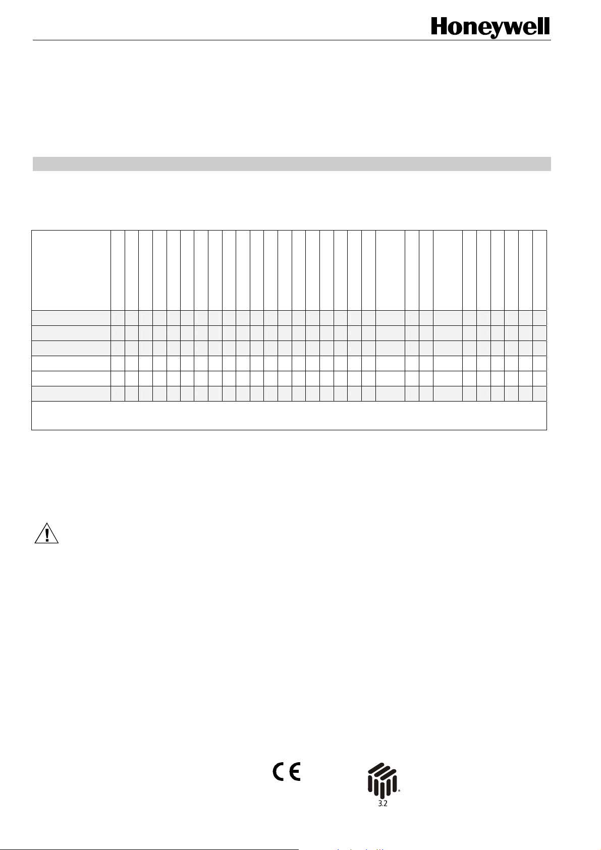
Depending on your application's hardware requirements, you can choose between the following different Excel 12 models:
Table 1. Overview of Excel 12 models
W7704A1004*1 X X X X X X X X X X X X X X X X X X X X X X X X X
W7704B1002*1 X X X X X X X X X X X X X X X X X X X X X X X X X X X
W7704C1000*1 X X X X X X X X X X X X X X X X X X X X X X
W7704D1008 X X XX X X X X XXXXXXXXX X XX X X X XXXX
W7704D1016 X X XX X X X X XXXXXXXXX X XX X X X XXXX
W7704F1003*1*2 X X X X X X X X X X X X X X
*1 These hardware versions have been discontinued.
2
The hardware variant W7704F1003 is cost-optimized for light control and does not support hardwired wall modules.
*
BEFORE INSTALLATION
IMPORTANT
It is recommended that the Excel 12 be kept at room
temperature for at least 24 hours before applying
power; this is to allow the evaporation of any
condensation resulting from low shipping / storage
temperatures.
short housing
long housing
24 Vac
230 Vac
binary input 1
binary input 2
binary input 3
binary input 4
relay 1 (N-O)
relay 2 (N-O)
relay 3 (N-O)
relay 4 (C-O)
relay 5 (C-O)
triac 1
triac 2
triac 3
traic 4
triac 5
triac 6
wall module LED
output
AI1 (NTC20k + V)
Standards
CE-certified according to EN60730-1.
Weight
Short housing: 400 g
Long housing: 860 g
AI2 (NTC20k)
AI3 (fan speed /
bypass)
AI4 (setpoint)
AI5 (NTC20k + V)
AI6 (NTC20k)
AI7 (NTC20k + V)
AO1 (0...10 Vdc)
Mounting
CAUTION
To avoid electrical shock or equipment damage, you
must turn off the power supply before attaching /
removing connections to/from any terminals.
Safety
Temperature Limits
• Ambient operating limits: 0…+50 °C at 5…90% r.H.
• Ambient storage limits: -30…+70 °C at 5…90% r.H.
Protection Standard as per EN60529
• IP20 without protection covers
• IP30 with protection covers
Software Class as per EN60730-1
Class A
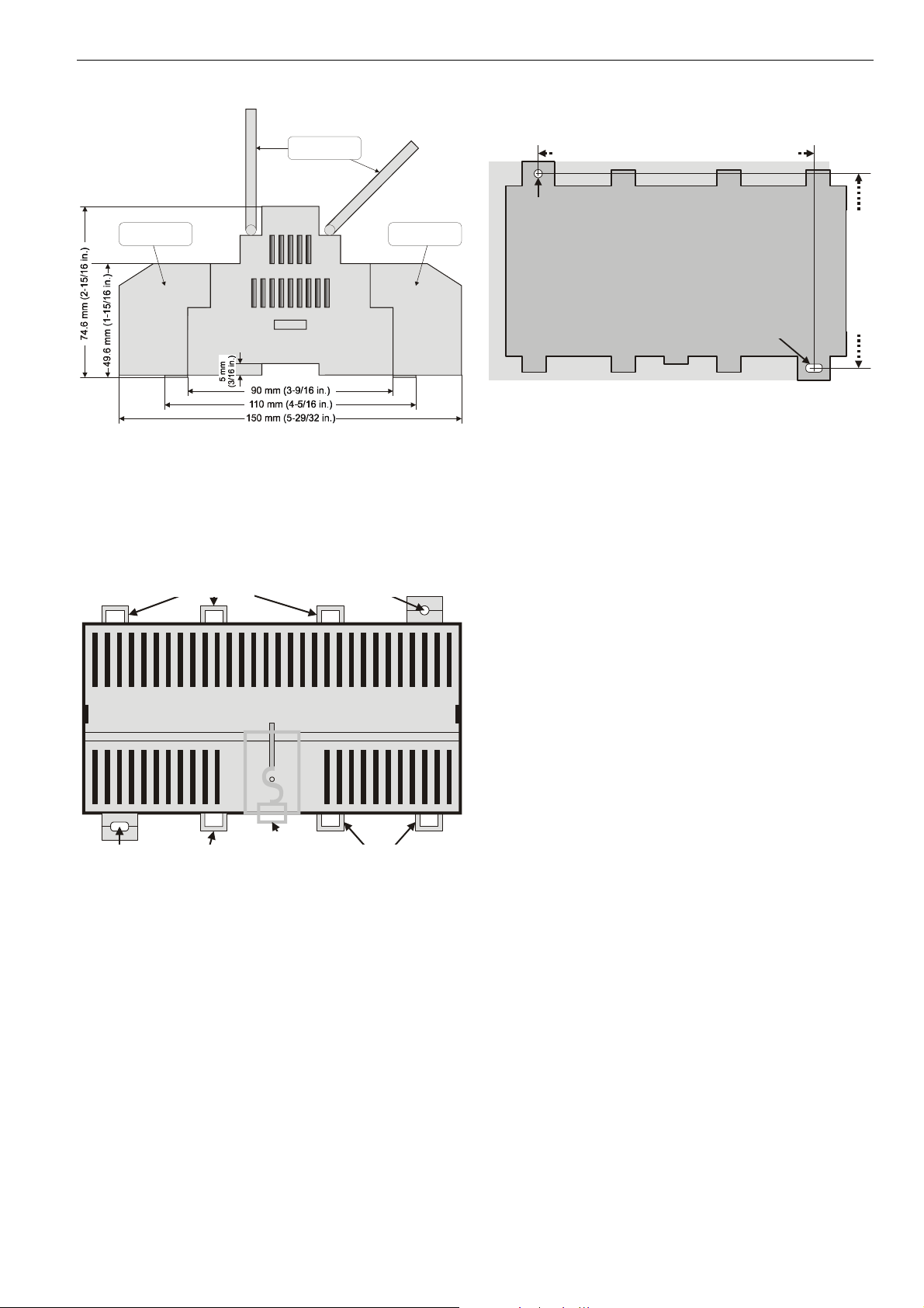
The Excel 12 is available with either short (W x L x H =
126 x 76 x 110 mm) or long (W x L x H = 180 x 76 x 110 mm)
housings (see Fig. 1). The mounting procedures are similar
for both sizes.
The Excel 12 is suitable for mounting on a standard rail (DIN
EN 50022-35 x 7,5) and for installation in wiring cabinets, in
fuse boxes, and on walls/ceilings.
AO2 (0...10 Vdc)
® U.S. Registered Trademark
Copyright © 2009 Honeywell Inc. EN1B-0201GE51 R0209E
All Rights Reserved
Page 2
EXCEL 12 MODULES
terminal protection
cover (optional)
swivel label
holders (optional)
terminal protection
cover (optional)
Wall/Ceiling Mounting/Dismounting
short housing: 100 mm; long housing: 154 mm
round hole
(diameter: 4 mm)
Fig. 1. Excel 12 housing (side view)
DIN Rail Mounting/Dismounting
The unit can be mounted onto a DIN rail simply by snapping it
into place and securing it with a stopper to prevent sliding. It
is dismounted by gently pulling the stirrup located in the base
of the housing (see Fig. 2).
screwing nose
(round hole)
eyelets for
cable binders
screwing nose
(oval hole)
Fig. 2. Housing base (view from below)
eyelets for
cable binders
eyelet for
cable binders
stirrup;
pull to dismount
from rail
oval hole
(4x7 mm)
Fig. 3. Drilling template (view from above)
The unit can be mounted on walls or ceilings in any
orientation desired. In the case of ceiling mounting, however,
it should not be operated at ambient temperatures exceeding
45 °C. The unit is mounted by inserting 3.5-mm dowel screws
through the corresponding screwing noses.
Optional Use of Terminal Covers
After mounting the Excel 12 onto the wall or ceiling, provide
for cable access by snipping out the terminal protection
covers' cut-out tabs and snap (by hand) the covers (available
in packs of 8) into place onto the housing. To remove a cover,
place a screwdriver in the leverage slot (see Fig. 10 on page
7) and pry it loose.
Terminal Assignment
The terminal blocks are arranged on two sides of the
controller: the relay side and the low-voltage side.
• The relay side consists of a single row of terminal blocks
for the connection of cables to the relays. In the case of
models with 230 Vac power supply, the 230 Vac power is
also connected on this side.
• The low-voltage side consists of two rows of terminal
blocks for the connection of cables to all other input /
outputs. In the case of models with 24 Vac power supply,
the 24 Vac power supply is also connected on this side.
NOTE: According to VDE guidelines, it is not allowed to mix
low-voltage and high-voltage signals on the relays.
NOTE: For controlling thermal actuators, we recommend
using the 24 Vac models, which provide more
current.
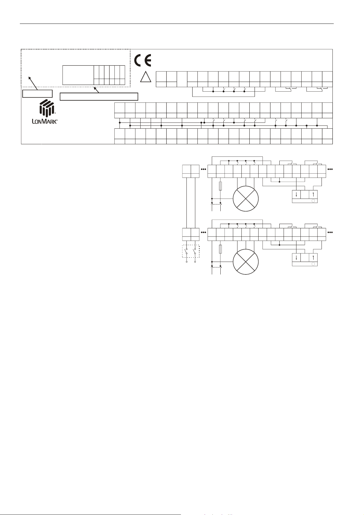
Every Excel 12 is equipped with a terminal assignment label
on the top of the housing (see Fig. 4). The terminal assignment label is a plastic part displaying the maximum
complement of I/O's.
The small sticker in the upper left corner provides modelspecific information, e.g. the date code, the type of power
supply, that terminals 36-38 (triac outputs 5 and 6) are not
connected, and that terminals 1, 2, 22, and 23 may be used
as 24 Vac output terminals, only (secondary side of the builtin transformer).
long housing: 100 mm
short housing: 100 mm
EN1B-0201GE51 R0209E
2
Page 3
W7704A1004
1401
date code
230 Vac +10/-15%; 20VA
50/60 Hz; Rel.Com. Max 6A
IP30 with terminal cover
X: not used
O: out, only
1, 2
45-52
53-58
36-38
43, 44
22, 23
XOO
model-specific information
24V~
24V~
0
~
23
22
24V~
24V~
0
~
21
LON
24
LON
0
Power
Power
!
BI3
LON
0
2
1
1
LON
2625
BI1
0
2
5
43
Fig. 4. Example terminal assignment label for W7704A1004
Power Supply
General Information
NOTE: Local wiring guidelines (e.g. VDE 0100) may take
precedence over recommendations provided in these
installation instructions.
NOTE: To comply with CE requirements, devices having a
voltage of 50...1000 Vac or 75...1500 Vdc but lacking
a supply cord, plug, or other means for disconnecting
from the power supply must have the means of
disconnection incorporated in the fixed wiring. This
means of disconnection must have a contact
separation of at least 3 mm at all poles.
All wiring must comply with applicable electrical codes and
ordinances. Refer to job or manufacturers’ drawings for
details. Use a min. of 18 AWG (1.0 mm
14 AWG (2.5 mm
2
) for all power wiring.
If power is supplied via a T terminal plug, individual Excel 12
modules can be disconnected from the power supply without
disturbing the operation of other devices powered by the
same source.
Models with 230 Vac Power Supply
Models with 230 Vac power supply are equipped with a builtin 24 Vac transformer, the secondary side of which can be
used to power external devices. The max. current at the field
device supply terminals and all triac outputs together must not
exceed 300 mA continuous.
NOTE: Do not connect external 24 Vac on models with
230 V power supply!!
These models have a long housing (180 mm). The power
supply (230 Vac [-15% / +10%], 50/60 Hz) is connected to
terminals 43 and 44. Terminals 1, 2, 22, and 23 are
connected to the secondary side of the built-in 24 Vac
transformer; these terminals must not be used for connecting
an external transformer. The terminals can be used to power
e.g. an active sensor.
2
) and a max. of
EXCEL 12 MODULES
Ho ne ywe ll
BI3
27
BI1
~
BI4
0
Y
BI2
0
Y
N
BI4
Y
BI2
Y
0
Power
Power
0
Power
Power
43
230 Vac
+10% / -15%
QLQN
Rel123
COM
Tria c
T1,2
COM
24V~
24V~
Out 0
Out ~
109876
~
~
44
Rel1
NO
Tria c
2
1
AI1
Y
QLQN
4 A
NL
QLQN
4645
4 A
NL
Rel123
COM
Rel123
COM
47
Rel2
NO
T3,4
COM
AI2
Y
1211
Rel1
NO
Rel1
NO
NO
Tria c
3
AI3
Y
13
Rel2
NO
LOW
FAN
Rel2
NO
LOW
FAN
QL
QNRel3
T5,6
Tria c
COM
4
LED
AI4
Out
Y
14
QNRel3
NO
HI
MED
QNRel3
NO
HI
MED
Rel4
Rel4
NC
COM
Tria c
AI5
1615
545352515049484746454443
Triac
6
5
AI5
0
Y
17
Rel4
Rel4
COMQL
Rel4
Rel4
COMQL
Fig. 5. Connection to 230 Vac power supply
NOTE: The max. current at the field device supply terminals
and all triac outputs together must not exceed
300 mA continuous. Disregarding these limits can
result in the destruction of the built-in transformer.
When not supplying external devices with 24 Vac, these
models have a power consumption of under 17.5 VA.
Models with 24 Vac Power Supply
These models have a short housing (126 mm). The power
supply (24 Vac [±20%], 50 or 60 Hz) is connected to terminals
1 and 2. Terminals 22 and 23 may be used to connect further
devices to the same 24 Vac power supply.
NOTE: Do not reverse the polarity of the power connection
cables and avoid ground loops (i.e. avoid connecting
one field device to several XL12's) as this may result
in short circuits damaging your device.
Rel5
Rel4
COM
NO
55
AO1
AO1
0
AI6
Y
Rel5
Rel4
COM
NO
NC
55
56
545352515049484746454443
sunblind
Rel5
Rel4
COM
NO
NC
54535251504948
sunblind
56
40393837363534333231302928
AI6
0
0
Rel5
Rel5
NO
NC
57
58
AO2
AO2
0
Rel5
NC
Rel5
NC
Y
42
41
AI7
AI7
0
Y
201918
21
Rel5
NO
57
58
M
Rel5
NO
58575655
M
Y
0
EN1B-0201GE51 R0209E
3
Page 4

EXCEL 12 MODULES
24 V
~
24 V
~
24 V
~
22
24 V
~
1
230 Vac
120 Vac
24 Vac
+/-20%
24 V
24 V
24 V
24 V
QLQN
Rel1
Rel123
45
4 A
NL
QLQN
4 A
NL
COM
Rel123
COM
NO
Rel1
NO
LOW
FAN
LOW
FAN
0
232322
0
221
0
0
fuses dependent
upon your transformer
Rel2
NO
Rel2
NO
QN
Rel3
NO
MED
NO
MED
HI
QL
QNRel3
HI
COM
5352515049484746
Rel4
COM
NC
54
Rel4
NC
54535251504948474645
NO
Rel4
NO
55
sunblind
55
sunblind
COM
56
Rel5
COM
NO
NC
57
58
0
M
Rel5
Rel5
NO
NC
585756
0
M
Rel5
Rel5
Rel5
Rel4
Rel4
Rel4
QL
Fig. 6. Connection to 24 Vac power supply
NOTE: The max. current at the field device supply terminals
and all triac outputs together must not exceed
500 mA continuous. Disregarding these limits can
result in the destruction of the built-in transformer.
The 24 V models have a power consumption of under 6.5 VA.
Wall Modules
The T7460 and T7560 Wall Modules can be used in conjunction with the Excel 12 to perform room temperature
sensing, set-point adjustment, fan speed manual override,
and occupancy bypass. When hardwired to the Excel 12, the
wall module's LED/LCD can be configured to provide
information about the effective occupancy mode, etc. (see
section "Configuration of the Wall Module's LED / LCD").
Table 2. Supported wall module functions
T7560
button
bypass
T7460C •
T7460D •
T7460E • •
T7460F •
left •
T7560A
middle •
right •
left •
T7560B
middle •
right •
NOTE: The intended use of the wall module's buttons must
be configured using Honeywell's LNS plug-in.
Example:
The T7560A has a left button which can be configured to act
as a “fan speed” button, a middle button which can be
configured to act as a “unit ON/OFF” button, and a right
button for “bypass.”
unit
ON/OFF
fan speed
Wall Module Connection
AI7
24V~
24V~
BI2
Out 0
Out ~
Y
9
8
com-
AI2
AI1
Y
Y
10
1211
1 2 3 4
set-
temp.
point
sensor
mon
AI3
Y
13
bypass
fan
AI4
14
LED
Y
5
in
LED
0
Out
1615
6 7 8
not
not
used
used
24V~
AI5
AI6
AI7
AI6
AI5
0
Y
Y
17
Excel 12
0
Y
201918
21
T7560
Fig. 7. Wall module connection
Configuration of the Wall Module's LED / LCD
When either a T7460 and T7560 Wall Module has been
hardwired to the Excel 12, its LED can be configured (using
Honeywell's LNS plug-in) to provide information about e.g.
overrides or effective occupancy modes. Further, in the case
of a T7560 Wall Module, its LCD can likewise be configured
to display such information.
Configuration of the LED to Display Info on Overrides
The wall module's LED can indicate if an override has been
activated by either the wall module's bypass button being
pushed or because the Excel 12 has received a network
command. Specifically:
• If the wall module's LED is OFF, then no override (from
the wall module or the L
effect.
• If the wall module's LED is ON continuously, the bypass
button or a network command has placed the Excel 12
into the "occupied" or "bypass" mode (however, if the bypass button is again pushed or if a cancellation network
command is received or if the bypass time expires, the
Excel 12 will return to its scheduled occupancy mode).
• If the wall module's LED flashes once per second, the
bypass button or a network command has placed the
Excel 12 into the "unoccupied" mode (however, if the bypass button is again pushed or if a cancellation network
command is received, the Excel 12 will return to its
scheduled occupancy mode).
• If the wall module's LED flashes twice per second, a network command has placed the Excel 12 into either the
"standby" or the "occupied" mode.
• If the wall module's LED flashes four times per second,
the Excel 12 is responding to a network management
"wink" command.
Configuration of the LED to Display Info on Occupancy Mode
The wall module's LED can also indicate the Excel 12's
effective occupancy mode. Specifically:
• If the wall module's LED is OFF, the Excel 12 is in the
"unoccupied" mode.
• If the wall module's LED is ON, the Excel 12 is in the
"occupied" mode.
• If the wall module's LED flashes once per second, the
Excel 12 is in the "standby" mode.
• If the wall module's LED flashes four times per second,
the Excel 12 is responding to a network management
"wink" command.
Configuration of the T7560 Wall Module's LCD
The T7560 Wall Module's LCD can be configured to display
various symbols providing the following information:
ONWORKS network) is currently in
EN1B-0201GE51 R0209E
4
Page 5

EXCEL 12 MODULES
2
2
• If is displayed continuously, the Excel 12 is in the
"occupied" or "bypass" mode; if it flashes, the given mode
has been overridden.
• If
is displayed continuously, the Excel 12 is in the
"standby" mode; if it flashes, the "standby" mode has been
overridden.
• If
is displayed continuously, the Excel 12 is in the
"unoccupied" mode; if it flashes, the "unoccupied" mode
has been overridden.
NOTE: If all three of these symbols are flashing simul-
taneously, the Excel 12 is responding to a network
management "wink" command.
•
means that the Excel 12 is OFF.
•
and mean that the Excel 12 is OFF, but that "frost
protection" has been enabled.
Connection of CO2-Sensor
A CO2-sensor (e.g. C7110D1009) may be connected to
analog inputs 1, 5, or 7 for air-quality control.
W7704
24 VAC
COMMON
CO2 IN
TEMP. SENSOR
BYPASS / FAN
TEMP. SETPOINT
LED OUT
9 10 11 12 13 14 15 16
3
1 2
4
5 6 7
Connecting to the LONWORKS Network
IMPORTANT
Do not bundle wires carrying field device signals or
LonWorks communications together with high-voltage
power supply or relay cables. Specifically, maintain a
min. separation of 3 inches (76 mm) between such
cables. Local wiring codes may take precedence over
this recommendation.
IMPORTANT
Try to avoid installing in areas of high electromagnetic
noise (EMI).
The unit must be wired to the L
IV 22 AWG (Belden part number 9D220150) or plenum-rated
level IV 22 AWG (Belden part number 9H2201504) nonshielded, twisted-pair, solid-conductor wire. When possible,
use Honeywell AK3781, AK3782, AK3791, or AK3792 cable
(US part nos.). See Excel 50/5000 LonWorks Mechanisms,
EN0B-0270GE51, for details, including max. lengths.
Use wire with a min. size of 20 AWG (0.5 mm
size of 14 AWG (2.5 mm
The unit is connected to the L
Fig. 9 via terminal pins 3 and 4 (black screw-type T terminal
plug) underneath the terminal protection cover (if present)
located on the low-voltage side. Terminal 24 and 25 are used
to connect further devices to the L
24V
24V
0
~
22
23
24V
24V
0
~
1
2
ONWORKS network using level
2
2
).
ONWORKS network as shown in
ONWORKS network.
LON
LON
1
2
24
25
LON
2
4
Excel 1
LON
1
3
) and a max.
24 VAC
COMMON
CO2 OUT
TEMP. SENSOR
BYPASS / FAN
TEMP. SETPOINT
LED IN
C7110D
Fig. 8. Connection of C7110D1009
LonWorks Communications
General Information
The Excel 12 is equipped with a free-topology transceiver
(FTT10A) for communicating on L
L
ONWORKS network is insensitive to polarity, eliminating the
possibility of installation errors due to miswiring.
Different network configurations (daisy-chain, loop, and star
configurations, or any combination thereof) are possible (see
also Excel 50/500 L
ONWORKS Mechanisms Interface
Description, EN0B-0270GE51).
All Excel 12 controllers feature a L
service button (see section "Troubleshooting" on page 6).
ONWORKS® networks. The
ONWORKS service LED and
24V
24V
LON
LON
0
~
22
24V
~
1
1
LON
2
25
24
Excel 1
LON
1
2
3
4
23
24V
0
2
Fig. 9. Connection to LonWorks (fixed terminals)
Depending upon the chosen network configuration, one or two
terminations (see section "L
ONWORKS Termination" on page
7) may be required.
Inputs/Outputs
Wiring the Inputs/Outputs
Use a min. size of 20 AWG (0.5 mm2) and a max. of 14 AWG
(2.5 mm
all input/output cables is 1300 ft (400 m).Two wires with a
total thickness of 14 AWG can be twisted together and
connected using a wire nut (include a pigtail with this wire
group and attach the pigtail to the individual terminal block).
Deviations from this rule can result in improper electrical
contact. Local wiring codes may take precedence over this
recommendation. Wire to the terminal blocks as follows:
2
) for all input/output connections. The max. length of
5
EN1B-0201GE51 R0209E
Page 6

EXCEL 12 MODULES
1. Strip 5/16 in. (8 mm) insulation from the conductor.
2. Insert it at the required terminal location, and tighten the
screw to complete the termination. Fix the cable using
cable binders if required.
Binary Inputs
The Excel 12 is equipped with dry-contact binary inputs. The
binary inputs are fast (i.e. the signal must be stable for
25 ms). The binary inputs are therefore suitable for processing signals which need to be handled quickly, e.g. light
switch input or sunblind UP/DOWN button. In the case of slow
signals, it is sufficient to use analog inputs, all of which can be
configured as slow binary inputs using Honeywell's LNS plugin.
Hardware Limits
• In order for the software to detect that a fast binary input is
closed, the resistance of the dry contact must be less than
200 Ω.
• In order for the software to detect that a fast binary input is
open, the resistance of the dry contact must exceed
50 kΩ.
• Signal must be stable for a min. of 25 ms.
NOTE: Push buttons connected to the Excel 12 must be
new. Specifically, it is not allowed to use push
buttons which have already been used for 230 Vac.
Binary Outputs
The triac outputs or relay outputs can be configured for
different functions.
Example: Floating Drives
You can choose to use two triac outputs or two relays to
connect a floating drive (no mixing of triac outputs and relays
allowed). Once the outputs have been configured using
Honeywell's LNS plug-in, floating actuators can be directly
connected to them.
Relay Outputs
The Excel 12 is equipped with up to two change-over relays
and up to three normally-open relays.
Hardware Limits
• A min. current of 50 mA is required to ensure a reliable
contact.
• The normally-open contacts are designed for a max.
continuous current of 6 A. The normally-closed contacts
are designed for a max. continuous current of 1 A.
• The max. combined allowable current flowing through all
relays simultaneously is 24 A (continuous).
• The max. peak in-rush current (20 ms) at the normallyopen contact is 80 A.
• Number of switching operations at
- Resistive charge: 200,000 (6 A)
- Inductive charge: 170,000 (6 A, cos φ > 0.6)
NOTE: If inductive components are to be connected to the
relays and if these relays switch more often than
once every two minutes, they must be prevented
from causing harmful interference to radio or television reception (conformance with EN 45014).
NOTE: Fluorescent lamps with electronic control gear often
have high switching currents. To reduce this
switching current, you could use current limiters (e.g.
EBN2 Schalk electronics) or install 10 m cable
(25 mm
2
) between the Excel 12 controller's relays
and the electronic ballast. If the analog input of a
dimmable electronic load is not a protective lowvoltage signal or if the analog signal is wired in the
same cable as the dimmable electronic ballast's
power supply, the Excel 12 system ground must be
earthed.
Triac Outputs
The Excel 12 is equipped with up to six triac outputs.
Hardware Limits for Excel 12 with 230 Vac Power Supply
• Low signal: 0 V; high signal: 24 Vac
• Maximum 250 mA continuous current in sum for all triac
outputs together
• 550 mA for max. 10 sec.
• cos ϕ > 0.5
Hardware Limits for Excel 12 with 24 Vac Power Supply
• Low signal: 0 V; high signal: 24 Vac
• Maximum 500 mA continuous current in sum for all triac
outputs together
• 800 mA for max. 10 sec.
• cos ϕ > 0.5
Analog Inputs
The Excel 12 is equipped with up to seven analog inputs, all
of which can be configured as slow binary inputs (in which
case the signal must be stable for at least 1.25 seconds) for
the detection of slow signals (e.g. from a window contact).
The analog inputs are configured using Honeywell's LNS
plug-in.
Table 3. Analog input usage
analog input voltage NTC wall module
AI1 X X e.g. CO2 or humidity
AI2 X room temperature1
AI3 fan speed or bypass2
AI4 set-point3
AI5 X X e.g. CO2 or humidity
AI6 X
AI7 X X e.g. CO2 or humidity
1
For all NTC inputs, temperatures of ≤ -50...-45 °C are interpreted as
being due to a sensor break, and temperatures of ≥ +145...+155 °C
are interpreted as being due to a sensor short-circuit.
2
A contact open for ≥ 10 seconds is interpreted as a sensor failure.
3
A resistance of > 15 kΩ is interpreted as being due to a sensor
break, a resistance of < 100 Ω is interpreted as being due to a
sensor short-circuit.
Analog Outputs
The Excel 12 is equipped with two 0...11 Vdc analog outputs,
each of which can drive a max. of 1.1 mA.
Troubleshooting
All models feature a LONWORKS service LED and corresponding L
outside on top of the module) for commissioning and
troubleshooting. When the service button is pressed, the
service pin message is broadcasted.
ONWORKS service button (accessible from the
EN1B-0201GE51 R0209E
6
Page 7

EXCEL 12 MODULES
See Table 4 on page 8 for a description of the meaning of the
various different possible behaviors of the L
ONWORKS service
LED. For more information on standard service LED behavior,
refer to Motorola L
ONWORKS Technology Device Data
Manual, page AL-190.
Possible Problems and Recommended Actions
Check if switching the power OFF/ON changes the
L
ONWORKS service LED's behavior. Please contact Honeywell
if this does not solve the problem.
leverage slot
long housing (with built-in transformer): 180 m (7-7/8 in.)
Short housing (without transformer): 126 mm (4-15/16 in.)
LonWorks
service button
LonWorks
service LED
ventilation slits
Accessories
Swivel Label Holders
For short or long housings (required for modules equipped
with manual override switches). Packs of eight.
• 24 Vac models (short), order no.: XAL_LAB_S
• 230 Vac models (long), order no.: XAL_LAB_L
Terminal Protection Covers
For short or long housings (required for wall/ceiling mounting).
Packs of eight.
• 24 Vac models (short), order no.: XAL_COV_S
• 230 Vac models (long), order no.: XAL_COV_L
LONWORKS Termination
One or two LONWORKS terminations are required, depending
on the given LonWorks bus layout.
Two different L
• L
ONWORKS termination module, order no.: 209541B
• L
ONWORKS connection / termination module (mountable
on DIN rails and in fuse boxes), order no.: XAL-Term
removable screw-type
3-pole terminal block
ONWORKS terminations are available:
l
l
e
w
y
e
n
o
H
m
r
e
T
-
L
A
X
4
3
L
L
O
O
N
N
shield shield
plug-in
jumper
34
15
06
LON
Termination
FTT/LPT Bus
FTT/LPT Free
Park Position
Fig. 10. Housing (top view)
Fig. 11. LONWORKS connection and termination module
7
EN1B-0201GE51 R0209E
Page 8

EXCEL 12 MODULES
Table 4. L
LED Flashing Pattern Meaning
1 LED remains OFF after power-up.
2 LED is ON continuously after first power-up. Defective hardware.
LED flashes at power-up, goes OFF, then comes ON
3
solid.
4 LED flashes briefly once every second.
5 LED flashes ON and OFF at 0.5 Hz. Node is unconfigured but has an application.
OFF duration ≈ 10 sec. Afterwards, the service LED
6a
turns ON and remains ON, indicating completion of the
blanking process.
OFF duration ≈ 1 sec. Afterwards, the service LED turns
6b
ON and remains ON.
OFF duration is 1...15 sec, depending on the application
6c
size and the system clock. Afterwards, the service LED
begins flashing ON and OFF at 0.5 Hz.
OFF duration is indefinite (1...15 sec to load internal
6d
EEPROM; remains OFF).
7 LED remains OFF after a short ON duration. Node is configured and running normally.
LED flashes ON for one second and OFF for one second
8
five times in succession and then remains OFF for five
seconds, after which the pattern is repeated.
LED flashes ON for one second and OFF for one second
9
four times in succession and then remains OFF for five
seconds, after which the pattern is repeated.
ONWORKS Service LED Behaviors and Meanings
Defective device hardware. Suspect power supply
problems, clock problems, or a defective Neuron Chip.
Node is applicationless.
This device is probably experiencing continuous
watchdog resets, or the external memory or EEPROM is
corrupt.
Using EEBLANK on a Neuron 3150 Chip-based custom
node.
First power-up with a new PROM on a Neuron 3150
Chip-based custom node. Application less firmware state
exported.
First power-up with a new PROM on a Neuron 3150
Chip-based custom node. Unconfigured firmware state
exported.
First power-up with a new PROM on a Neuron 3150
Chip-based custom node. Configured firmware state
exported.
Module has received a WINK command from the
network. Other physical outputs are unaffected.
There are two possible causes:
1. Coprocessor identification. After reset (power-up),
the Neuron Chip waits for the coprocessor's ID
message (sent periodically until acknowledged).
While waiting, the application remains OFF. This wait
status will remain if the hardware ID fails e.g.
because the Neuron application does not match the
hardware.
2. NEC/Neuron communication failure. If a NEC failure
(e.g. NEC application too big, sensor break, etc.) is
detected, the service LED flashes as described at
left, and continues doing so as long as the NEC
failure is recognized.
Manufactured for and on behalf of the Environmental and Combustion Controls Division of Honeywell Technologies Sàrl, Rolle, Z.A. La Pièce 16, Switzerland by its Authorized Representative:
Automation and Control Solutions
Honeywell GmbH
Böblinger Strasse 17
71101 Schönaich / Germany
Phone: (49) 7031 63701
Fax: (49) 7031 637493
http://ecc.emea.honeywell.com
Subject to change without notice. Printed in Germany
EN1B-0201GE51 R0209E
 Loading...