

Page 1
Honeywell
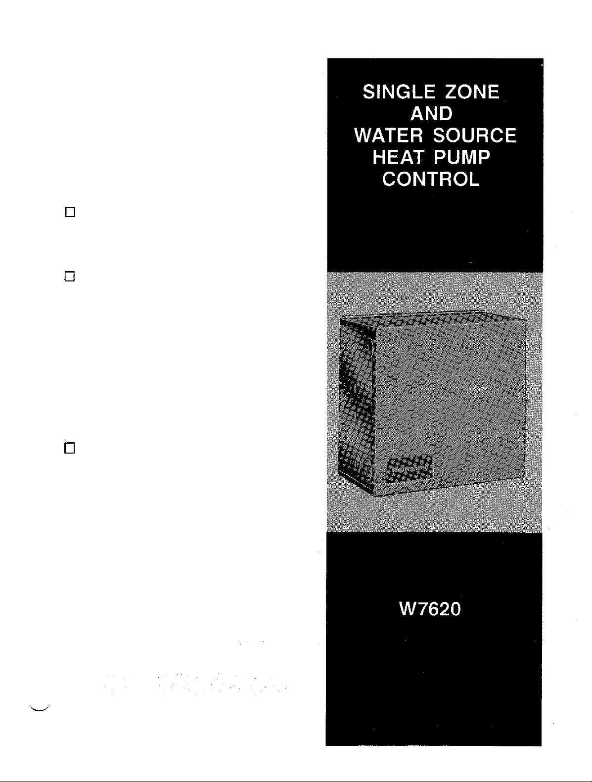
W7620
PROVIDES CUSTOMIZED CONTROL OF HVAC
SINGLE ZONE EQUIPMENT. SPECIFIC
FEATURES THIS SYSTEM OFFERS INCLUDE:
COMMUNICATION, APPLICATION FLEXIBILITY,
DIRECT DIGITAL CONTROL, EASY
INSTALLATION AND PROGRAMMING, AND
INCREASED EQUIPMENT RELIABILITY.
0
0
q
SINGLE
W7620 Base Controller provides:
-
four relay outputs
-
network communication
-
T7660 Space Temperature Sensor inputs
W7621 Expansion Input
ditional input point expansion on one board of up
to:
-
two resistive inputs
-
two digital inputs
-
two voltage inputs (one dry contact, one
extended 24 Vac input)
W7622 Expansion Output Point
ditional output point expansion on one board of
up to:
-
three analog outputs
-
three digital outputs
ZONE CONTROL
Point
Boards provide ad-
Boards
SYSTEM
provide ad-
0
T7660 Space Temperature Sensor provides up to:
-
one space temperature input
-
one space temperature &point
-
one override push button/LED indication
Cl Up to four heat/four cool conventional or four-
compressor
heat pump
q Flexible control options:
-
analog/humidity switch
-
packaged or integrated economizer
-
indoor
air quality switches
HG/KH
8/91
Form Number 63-4224
©Honeywell 1991
Page 2

SYSTEM DESCRIPTION . . . ; . . . . . . . . . . . . . . . . . . . . . . . . . . . . . . . . . . . . . . . . . . . . 3
INST~LATION........,..1..........................................
CHECKOUT
. . . . . . . . . . . . .
..1............~...........................11
SPECIFICATIONS. . . . . . . . . . . . . , . . . . . . . . . . . . . . . . . . . . . . . . . . . . . . . . . . . . 13
ACCESSORIES . . . . . . . . . . . .
..‘.......................................lS
7
WHEN PURCHASING REPLACEMENT AND
DISTRIBUTOR, REFER TO TRADELINE CATALOG OR PRICE SHEETS FOR COMPLETE ORDERING
IF YOU
PRODUCTS
1.YOUR LOCAL HONEYWELL
2. RESIDENTIAL AND BUILDING CONROLS
IN CANADA -
CANADA
HAVE ADDITIONAL QUESTIONS, NEED
OR
SERVICES;
RESIDENTIAL
MINNEAPOLIS, MINNESOTA 55422, (612)
AND BUILDING CONTROLS SALES
HONEYWELL LIMITED/HONEYWELL
M1P 2VP.
PLEASE WRITE OR
SALES OFFICE (CHECK WHITE PAGES OF YOUR PHONE DIRECTORY,. ASK FOR THE
INTERNATIONAL SALES AND SERVICE OFFICES IN ALL PRINCIPAL CITIES OF THE
MODERNIZATION
FURTHER INFORMATION
PHONE:
REPRESENTATIVE.
CUSTOMER
542-7500.
LIMITEE,
PRODUCTS FROM YOUR AUTHORIZED SYSTEMS
OR WOULD LIKE To COMMENT ON OUR
SERVICE HONEYWELL INC., 1885 DOUGLAS DRIVE NORTH,
740 ELLESMERE ROAD, SCARBOROUGH ONTARIO
NUMBER.
WORLD.
Page 3

The W7620
new
can conveniently monitor and
zone equipment.
System features include CNAP (Control Network
Automation Protocol) communication, application
flexibility, DDC (Direct Digital Control), network
integration, easy installation and programming, and
increased
The basic
capability to process
programs, and communicate along with other devices on
the CNAP
The W7620
DDC has a control loop which periodically updates
outputs as a
given set of algorithms.
Single
Zone Control System is Honeywell’s
line
of single
equipment reliability.
W7620
network.
zone control
Single
I/O
(Input/Output) data,
See W7620 family photo.
Single Zone
function
of a set of measured inputs and
products. The W7620,
control
individual HVAC
Zone
Controller has built-in
run
DDC
Controller is a DDC device.
the
The
advantages of DDC
are:
Control
The W7620
control loops for accurate control of single zone equipment
that prevents
comfort in the
Single Zone
temperature
zone.
Controller provides sophisticated
droop and provides greater
the RS-485 CNAP network. The CNAP
communication to multiple
well as to other
Module, 47640 NIU or a
a PC with ZM7603 Remote Monitoring
to the ZM7601 Configuration Tool/ZM7603 Remote
Monitoring
for a more detailed description.
Through the CNAP network, the controller can be
provided with information
only, or
controllers. ZM7601/ZM7603 software
provided
for
Figure 1.
a
The W7620 Zone Control System was designed for
application flexibility.
which is stored in EBPROM and by
and
be applied in a variety of applications.
network
W7620 Zone
controllers,
software
with information necessary for a group of
with periodic information on any controller data
monitoring, data gathering, or report generating. See
output requirements, the same
such as the
Q7650
PC Interface Card in
specification
specific
Simply
by changing
sheet,
Form 63-4272,
to its controlled
determining the input
W7620 controller can
enables
Controllers as
W7600
Control
software.
can, in turn,
Refer
the
algorithm
zone
zone
be
Maintainability
Use of a single programmed computer reduces
requirements for calibration checks because
fewer interconnected analog components. Periodic
recalibration is automatically
performed.
there
are
Reliability
EEPROM (Electrically Erasable Programma
Only Memory) and EPROM
Read Only Memory) hold the control program and
parameters
eliminating
the
(Erasable Programmable
need
for a
battery.
ble Read
Communlcatlon
Networking controllers together on a
using
CNAP software provides information for integration
of control functions, monitoring, trending, alarming, and
report
generation.
The W7620
stand-alone environment with distributed zone control
and
hard-wired time-of-day
applied as part of a
Single Zone
networked
Controller can be applied in a
functionality It can
system via connection
RS-485 network
also be
to
‘Ike W7620 Baseboard provides input dedicated to the
T7660 Space Temperature Sensor (space temperature,
remote
CNAP communication connections). The baseboard
provides four SPST
A variety of small point, single zone or heat pump
applications
The
one AC input, and two voltage
for a variety of inputs depending on application. One
W7621 input board
controller.
setpoint,
W7621
bypass switch with LED feedback, and
only
(Single
Pole, Single Throw) relays.
can
be met by using only the
Input Board
adds two resistive, one digital,
inputs that can
can
be
added
to the
W7620.
be used
W7620
Zone
3
63-4224
Page 4
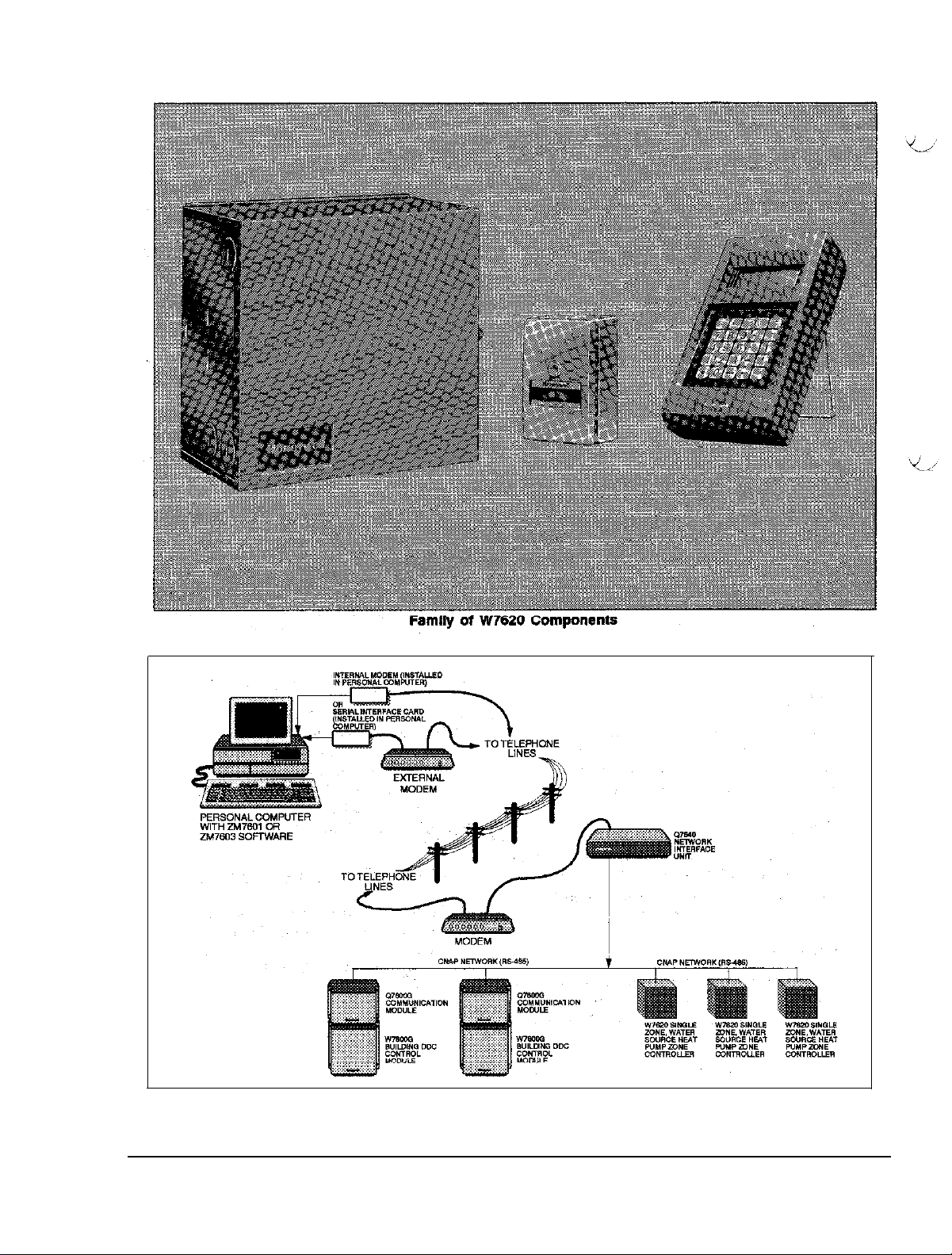
Figure
1 - CNAP Network Diagram
Page 5

The W7622 output board has a
on
depending
any type
The W7622 drives any output (for heat, cool, etc.), either
digital
relay outputs have both
closed contacts. The
The
‘I7660
Device) that is placed in the
Sensors are
adjustment dial or an occupant override push button with
status
LED (Figure 2). The push button allows setting
the heating or
the control system is in an unoccupied
can be
The LED indicates
are furnished with an RJ11 connector for local operation
of an
S7610
the T7660A-D Space Temperature Sensors Information
and
Installation
the model
can
be added to the
or
analog. Function depends upon application. The
is a platinum RTD (Resistive Temperature
available with or without an
cooliig
used
to initiate a
the
POT (Portable Operator’s Terminal). (See
sheet,
number.
normally open
analog
outputs are 0-10
zone
system to an occupied mode when
continuous unoccupied period.
override
Form
selection
One output board of
W7620
for temperature readings.
status.
These zone sensors
63-4219, for
of outputs
Zone Controller.
and
normally
Vdc.
integral setpoint
mode.
Also, it
more
details.)
The S7610
means to set, test, and monitor point and parameter values.
The POT utilizes the RS-485 CNAP nehvork for
communication and connects to
cable to an RJ11 jack at
Sensor, or to an RJ11 jack inside
The POT
network.
63-4225, for information on operation. See Figure 3.
POT
is a hand-held &vice that provides a
the T7660
can
communicate to
See the S7610 Zone
the
controller through a
Zone
Temperature
the
controller
any controller on the
Control
POT Guide,
case.
Form
Page 6

Figure
3 -POT (Portable Operator’s Terminal)
Page 7

When
installing
1.
Read these
them could damage the product or cause
hazardous condition.
2.
Check the
section and on
product is suitable for the application.
3. The installer must be a
service or installation technician.
4.
After installation is complete, check system
operation as provided in
5.
Verify
with
procedures.
6.
Verify that the T7660
installed in
T7660
this product . . .
instructions
ratings
that the W7620s are
the
job
drawings
accordance
Specification Sheet (63-4219).
carefully. Failure to
given in
the
product to make
the
SPECIFICATION:
trained,
experienced
these instructions.
installed in
and
these installation
Space
Temperature Sensor
with job drawings and
sure that the
accordan
a
follo
the
surface-before removing the W7621 or W7622
expansion board from the antistatic bag.
Failure to do so might damage the board.
I
Mount
the
wiring, servicing
controller in a location that allows clearance
Remove the cover by loosening the two side
screws
location appropriate to the equipment being
controlled.
secure the controller to the mounting surface
through the four
(Figure
and removal of
4) and mount
screws
key
holes
inside
the
cover.
the controller in a
(obtain locally) to
the case,
for
1.
2. Use No. 8 sheet metal
I
Disconnect power supply before beginning
installation
equipment damage.
radiate radio frequency energy. not installed
and used in accordance with the instruction
manual, it may cause interference to radio
communications. Pursuant to FCC Rules,
Subpart J of Part 15, this equipment has
been tested and found to comply with the
limits for a Class A computing device. These
limits are designed to provide reasonable
protection against interference when operating
in a commercial environment. Operating this
equipment in a residential environment is
likely to cause interference, in which case the
user at his own expense will be required to
take whatever measures necessary to correct
the interference.
to prevent electrical shock and
3. Test the
4. Replace and secure the controller cover after
wiring
controller
is
complete.
and equipment operation.
Mountlng Additional Boards
To install additional input or output expansion boards
(W7621 or
on
following:
1.
2.
3. Lean the input or output board in at the base to
4. Snap the board into place
5. Secure the board into place by applying and
W7622) which
the
base board assembly (Figure 5) complete
Align the
baseboard with
the input board
Align the white plastic standoff tab with the hole
located near the lo-pin connector.
catch the metal tab located on the bottom of the
controller.
tightening the two board screws provided with
each expansion
IO-pin
are
not
manufacturer installed
connector (J4) or
the
10-pin inverse
(J15)
or output board (13).
board.
the
(J5) on the
connector on
7
63-4224
Page 8

,&Knockout for
h
Double knockout for
l/2
in. conduit fittings.
l/2
or
3/4
in. conduit fittings.
Figure 4 - W7620 Mounting
STANDOFF HOLE
PLASTIC STANDOFF
Figure 5 -Mounting Additional Board
8
PIN CONNECTOR
10
Page 9

r
If securing screws are not used, the
expansion board will
will
result in improper operation or damage to
the
device.
I
not be
grounded. This
Pull the
controller
terminals marked CNAP +/- (Figure 6).
I
pair of CNAP communication cables to each
on
the network and connect to the screw
NOTE
I
NOTE
The
W7620
63-4220,
designations to function
wiring
and the J/O Control Function Cross-Reference provided
on
the
Wire as follows:
1.
strip % inch (5 mm)
conductor.
2. Insert the wire in the required terminal location
and tighten
Figure 6 illustrates the terminal arrangement in the
controller. All
terminal arrangement similar to
Single Zone Application Guide, Form
provides information on corresponding
was done according
inside cover of
screw terminal.
controller
the
connections.
to the wiring diagram provided
W7620.
insulation
models are
that
Verify that the
from the
furnished with
shown in
terminal
this
figure.
a
I
Power Wire Lengths
1. Power requircmcnts limit 24 Vac power
transmission distance. The following data can be
used in calculating load versus wire length:
Device
VA
W7620 3.9
output relay
Analog output 0.6
Power relay 4-10
2.
The power relay load rating depends on the relay
can
used. Power relays
current
from separate 24 Vac supply.
3.
The operating voltage range for
to 30 Vac.
Pull a pair of 24 Vac
or
shared transformer to each controller on
ml connect to Terminals TR
be wired to draw coil
power
cables from either an isolated
0.5
the
and
TR earth-ground.
W7620 is 20
the net
work
Figure 6 -Terminal Designation Label
Page 10

T and Al). See the T7660 Space
Sensor
correct temperature to
cross-reference.
specification
sheet, Form 63-4219,
measure resistance
Temperature
for the
value
3.
Observe the fan or measure
expected result is not achieved, measure the
resistance across the correct
OUT1 A and C). The resistance should hold at
approximately
1.0 when the output is ON.
the
output. If the
terminals
(e.g.,
4.If long sensor
supplied to the W7620 by both
sensor and the leadwire for greater accuracy.
wiring
is used,
m-
the
temperature
resistance
Output Point Test Procedures
Testing outputs consists of observing the analog or digital
output states of physical points to see that the value
state is comparable to the point value as displayed on
the S7610
devices can be used to
known state to facilitate checkout.
procedures:
1.
2. Measure or observe the output
3.If the output does not follow the command
4. Clear the override condition.
POT
or ZM760l/ZM7603 software. These
override
Set the
value with the S7610 POT or ZM7601/ZM7603
software.
turns
override condition, isolate
checking connections and measurements at
output destination as
override
on).
on an output point to a desired
well as
the output point to a
Use
the following
condition
the
problem by
at the W7620.
(e.g., fan
or
the
Example:
The
following
any
one of the outputs, 1-7, depending on
output options
Zone/WSHP
63-4220.
1.
Display Fan (OUT.) on the S7610 POT or
ZM7601/03 software.
2. Set into override the point to the desired state, ON
or OFF.
procedure is for Fan (can be
selected,
Application
see W7620 Single
Guide, Form
Page 11

The following steps for complete checkout and testing
of a W7620 are described fully below. The procedures
are
as follows:
1.
Check W7620 installation and wiring, including
power to the W7620.
2.
Start-up W7620 (connect S7610 POT or
ZM7601/ZM7603 software) and assign a network
node address and application (even when using
device in a nonnetworked application). Refer to
W7620 Application Manual, Form 63-4220.
3. Test analog and digital input points
4. Test analog and digital output points.
5.
Verify
parameter point values.
1.
Verify that the connections between the W7620
and peripheral equipment are secure.
2.
Verify that
grounding
is correct in
accordance
with
GROUNDING in this guide as follows:
a.
Verify that each W7620 case is grounded
when the
individual
b. Verify that all W7620 cases are grounded
when the
c-on
c.
Verify that if
transformer
side is connected to earth-ground on the
W7620 (TR earth-ground).
d.
Verify that neither of the CNAP network wires
is grounded or
e.
Verify that the
network wires is correct, positive to positive
and negative to negative in alI cases.
3.
Verify the CNAP network termination and biasing
resistors
Network Interface Unit
(63-4290).
4.
Turn on power and
least 20 Vac at Terminals TR and TR
earth-ground.
W7620s are
transformers.
W7620s
transformer.
the
secondaries, that the grounded
are installed in accordance with 47640
powered from
are powered from a
application calls for grounded
connected
polarization
verify
to the 24 Vac wires.
of the CNAP
specification
that each W7620 has at
sheet
Testing physical points requires either the actual sensor
be at a known
known value or digital state be applied to the input point
terminals.
condition of the controlled equipment must be known,
or the output terminals of the W7620 can be measured
with an indicating device or meter. The Hardware
Configuration Data table shows all of the possible physical
points with terminal designation and use. The General
Guide for Input/Output Point Testing table can be used
to determine what can be used to provide inputs and
what to use to
value or
In the case of physical output points, the output
measure
digital state, or that a simulated
outputs.
Input Point lest Procedures
1.
Read point value through the S7610 POT or the
ZM7601/ZM7603 software to verify approximate
analog value or digital state. If the data is
acceptable, proceed to the next point.
2.
For analog points that display FA (sensor
next to the
a.
Provide a known measurable value to the input.
b. Compare the input point value displayed on
the POT or ZM7601/ZM7603 software with
the known value.
c.If the difference between the two values
exceeds the acceptable range, isolate the
problem by taking a measurement at the
input
wire), and the W7620.
Example:
The following is the procedure for input
Point 1 (SPACE TEMP).
1.
Measure the
Fahrenheit
thermometer, near the actual sensor.
2.
Verify
ZM76Ol/ZM7603 software
expected temperature.
3.
If the accuracy of the measurement is in question,
measure resistance supplied by the sensor at the
Space Sensor itself to fmd sensed value Terminal
engineering
source, the conductors (e.g., cable,
input
with another source, such as a
that the S7610 POT or the
unit:
space temperature in degrees
value
reads the
failure)
Page 12

or removing connections from Terminals TR
and TR earth-ground.
2. To disable a controller, remove both legs of
I
the AC power. Removing only one leg may
prevent other controllers on the same
transformer from communicating on the
CNAP network.
I
L
The
W7620
Zone Control System must be earth-grounded
W7620
at each cluster of
controllers powered by a single 24 Vac transformer). Use
No. 18 AWG or larger copper conductor
earth-ground, such as a water pipe driven into the earth
or the ground connection found within the power
distribution panel. The power distribution panel must be
earth-grounded per National Electric Codes. Do not “se
or
the ductwork
necessarily provide a good ground. The following
provides
1.
Earth-ground one
W7620s
the wiring conduit since these do not
grounding details:
connected to a given
controllers (one or mote
run
W7620
within a group of
transformer.
W7620
to a known
Connect the
screw on the
ground wire
W7620
chassis. See Figure 7.
to the
green ground
connect the same side of the
transformer secondary to the same terminal
number on each W7620.
2.
Grounded Transformer Secondaries: If the
has
Transformer
necessary
ohm meter to test for conductivity between one
side of the transformer and the suspected
grounding plane (usually the controller chassis).
If one side of the transformer is grounded,
connect
earth-ground
earth-ground).
a grounded
to identify the
the
grounded
connection on the
secondary,
grounded
secondary
it is
side. Use an
to the
W7620 (TR
to connect grounded secondary to
will cause damage to the
Tie each
W7620
(using ground
screw) together in the cluster.
Earth-ground each cluster at some
accessible point that is a good
distribution ground.
Page 13

Electrical Ratings
Supply
Voltage
Current
System
Inputs:
Outputs:
Relay (expansion)
Draw
Resistive
Voltage 0-10 Vdc with 2
Digital
AC
Analog O-IO
Relay (base)
Temperature Ratings
Ambient
20-30
Vac, 50 or 60 HZ
maximum at 30 Vac,
8.5 VA
29104370 ohm (-40 to 265°F temperature range with
platinum sensors)
Vdc
j External contact (switch,
Input
Up to three 24 Vac
from same
separately or together to determine the final state of input.
2.0 amp maximum running, 7.5
60 Hz
1.6 amp maximum
60
40 to 110°F [4 to 44°C]
transformer, All three Inputs
Vdc,
20 mA maximum
Hz
running,
50 or 60 HZ
overrange
relay or
source indicating digital
transistor) Into
can
amp
In-rush at 30 Vac, 50 or
7.5 amp In-rush at 30
15
Vdc,
response to
be used
Vac,
15
call
50 or
5-95%
RH,
noncondensing
any surface using
temperature, and
ctrical,
anchoring screws (not provided
humidity ratings
can
be
Page 14

bl
Knockout for
Q
Double knockout for 1 /2 or 3/4 in. conduit fittings.
l/2
in. conduit fittings.
Figure 8 - W7620 Dimensions
14
63-4224
Page 15

Base Unit
Input
Expansion
(with
cover)
Boards
Damper Actuator
Use with
W7459 Economizer Logic Module,
modulating spring
Page 16

This
digital apparatus
for radio noise
limits
set
out
I”
the Radio
Canadian Department of Communications.
Dear Customer,
welcome
We
this publication.
Your assistance
provide
HONEYWELL MINNEAPOLIS, MN
Australia, Canada, Finland, France, Germany,
your comments
is greatly appreciated and will enable us to
better technical information
does not exceed the
emission
I-
and suggestions
fmm
Regulations Of the apparelIs
for you.
55408
INTERNATIONAL Sales offices I” all
digital apparatus
Canadian EMI
Class A
for Improving
Japan,
Mexico,
Le prdsent apparelI “wn&-lque “&net pas
rad4c&ctiques
le R@lament SW le bmufllege
!aar 18 mlnlstBr@ des Communlcstions du
send your
Please
Honeywell Inc.
Bluewater
8500
Albuquerque. NM 87121-1958
Technical Editor
ATTN:
Netherlands, Spain,
depassant les llmltes appllcables BUX
nutirlques de la
comments
N.W.
principal cities
Taiwan, United Kingdom, U.S.A.
Classe
radl,Mktrlqua
and suggestions
of the
de
btults
A praadtes dens
Bdlctd
Canada.
to:
world. Manufacturing
PRINTED IN U.S.A.
In
 Loading...