

Page 1

WebStat W7350A1000
QUICK START GUIDE
PRODUCT DESCRIPTION
WebStat W7350A is a web-based building manager that
leverages the Niagara
communicates over the LonWorks network to perform building
management control of T7350 thermostats through a web
browser. It runs building management applications such as
Trending, Scheduling, and Alarming.
WebStat W7350A acts like a network time master to
synchronize the time and date in thermostats linked to it with
its own time and date or with the Internet time servers. Its
Device Discovery feature enables you to discover online
thermostats. You can perform User Administration and Access
Level control. System Administration functions such as
configuring network settings, site information settings, system
& control network, date and time settings, and new module
installation are also enabled.
TM
architecture and T7350 Wizards. It
CAUTION
Make sure that there is not more than one WebStat
accessing the same Lon network simultaneously.
If more than one WebStat accesses the same Lon
network simultaneously, there may be problems in
downloading and uploading parameters.
WebStat is compatible with IE 6.0 SP2. Suggested
screen resolution is 1024x768 pixels.
BEFORE INSTALLATION
Prior to installation, ensure you have the following:
• WebStat W7350A1000 Mounting and Wiring
Instructions Document
• WebStat
• Power Adapter
• LON Connector
• Ethernet CAT 5 cable with RJ-45 connectors
• Laptop/PC that will be used to perform initial
configuration
• Cable for Grounding (Refer JACE-2 Mounting and
Wiring Instructions)
• The installation network and Internet requirements
determined
For access from a local or wide area network (LAN/WAN),
WebStat will be connected to the LAN/WAN. Ensure the
presence of a network administrator. In case there is no
network administrator, it might be necessary for the installer or
the facility manager to consult an independent network
professional. Internet access to WebStat is frequently
provided through a LAN/WAN. Prior to installation, identify the
procedures for connecting WebStat to the LAN/WAN and gain
Internet access.
Network Security
As with any Internet web server, WebStat is subject to attack
by “hackers”. While WebStat is supplied with the best
available internal protection, a network “firewall” must be used
if Internet access is provided. Review the Internet, LAN, or
WAN provisions for installation and determine the appropriate
firewall requirements.
IMPORTANT
• When connecting WebStat to the Internet directly, or
through a LAN or WAN, use of additional external
security measures such as a “firewall” is strongly
advised.
• When connecting WebStat directly to the Internet from
a cable/DSL modem with no network, a firewall must
be established by adding a router. (Simple switches
and hubs are insufficient.)
• Most routers used with cable/DSL modems provide a
significant level of hardware protection and network
address translation (NAT), and have the ability to
implement a software firewall as well. Such routers are
widely available at nominal cost.
Generally, local and wide area networks have sophisticated
firewall protection and it is necessary to work with a network
administrator to install WebStat properly. Network
reconfiguration might be needed to support WebStat. If the
installer or end user does not have the expertise required to
determine the network capabilities or to set up an appropriate
firewall, consult a network specialist.
63-2657-01
Page 2

WEBSTAT W7350A1000
IMPORTANT
• Networks configured with the Microsoft® Windows®
Network Setup Wizard as a proxy server (the
recommended wizard procedure) may not support
WebStat.
• Installing WebStat in such a network requires
reconfiguring the network for peer-to peer operation.
WebStat has been designed with many features to promote
Internet security. The most basic is the user ID and password
access to the system. WebStat has a default user ID and
password for initial installation. After installation, each
individual user is provided with a unique ID and password.
Internet best practices recommend IDs and passwords that
are eight characters or more in length with a mix of alpha and
numeric characters. Best practices also require individual
users to change passwords periodically. As with any system,
when personnel changes occur, old IDs and passwords must
be deleted and new ones assigned.
WebStat closes all unused internal software access ports. It is
designed to allow access through HTTP and Niagara FOX
ports during normal system operation.
Initial setup of WebStat requires a PC to be physically
connected to WebStat’s Ethernet port. When configuration is
completed, remove the PC – WebStat Ethernet connection.
NOTE: Future upgrades and service packs for WebStat will
be available on the Internet.
CAUTION
It is not suggested to use DHCP addressing
mechanism. The IP address is dynamically
assigned to WebStat. Unless the IP address is
known, WebStat cannot be accessed. DHCP
addressing mechanism should be used only when
there is a way to know the IP address assigned to
WebStat such as DHCP logs and Router
Administration User Interface.
Uniform Resource Locator
A Uniform Resource Locator (URL) is required to address
WebStat with Microsoft® Internet Explorer. In many
installations, the URL will be routed through a Dynamic Name
Service (DNS) to address WebStat. However, DNS is not
required for installations using an Ethernet DHCP address. If
DNS is used, the information for WebStat setup data must be
obtained prior to setup. This can require obtaining a registered
domain name from a Domain Name registration service. The
information should be available from the facility’s network
administrator and/or ISP. The processes for setting up DNS
service vary depending on the ISP, DNS service, and the
user’s LAN/WAN operating policies and are beyond the scope
of this document.
Using a DNS address, the URL is in the form of protocol:
//FullyQualifiedDomainName/resource (See definitions
below).
Setup Information Requirements
Specific information about the network is required to configure
the network interface of WebStat. The section titled Setup
Data Descriptions identifies the data required for each
configuration option. This information should be gathered prior
to setting up WebStat. Appendix A is provided to record and
collect all applicable data required to configure WebStat.
In local area network/wide area network (LAN/WAN)
applications, the data required will be provided by the network
administrator.
Static or Dynamic Address Option
It is necessary to provide an IP (Internet Protocol) address for
WebStat in order to communicate with it.
WebStat supports both static and Dynamic Host Configuration
Protocol (DHCP) IP addressing. A static IP address is one that
is permanently assigned to WebStat and is provided by the
ISP or LAN/WAN network administrator.
A dynamic IP address is one that is assigned by another
network device (DHCP Server) and can change based on
rules established for the network.
Alternatively, you can use the IP Address to access WebStat.
The URL will be in the form of protocol: //IP_Address (See
definitions below).
WebStat URL COMPONENT DEFINITIONS
• protocol = http
IMPORTANT
The protocol must be entered as ‘http’. Entering
incorrect protocol results in an error message, “The
page cannot be displayed”. Internet Explorer defaults
to the http protocol which results in the error message FullyQualifiedDomainName (FQDN) = hostname.domainname
• domain.name = the domain name assigned by the ISP or
network administrator.
— The domain name must be registered if it is to be used
through the Internet.
— WebStat installed in a LAN/WAN must be provided by
the network administrator.
— WebStat installed in a small network using a Cable/
DSL router can require configuring the router DMZ or
port redirection to provide access.
• hostname = the host name for WebStat (host) assigned by
the installer during configuration. Refer to Setup Data for
Configuration Options.
• IP address = the static IP address assigned by the ISP,
network administrator, or the dynamic IP address assigned
by the DHCP host.
63-2657—01 2
Page 3

WEBSTAT W7350A1000
Setup Data for Configuration Options
There are two network configuration options. Table 1 captures
the data required for each type of configuration. The Setup
Data Descriptions section describes each configuration data
prompt with an indication of where the data can be obtained.
If the installer is not familiar with the processes required to
configure network devices, consult a networking specialist.
Table 1.
IP Address
Options Static DHCP
IP Address X
Network Mask X
Default Gateway X
Primary DNS
Server
Local Host Name XX
Local Domain
Name
Setup Data Description
[IP Address] WebStat IP address - user assigned
This is the LAN/WAN IP address which applies to WebStat in
static IP configurations. It is not applicable in DHCP
configurations. The IP address consists of four sets of
numbers separated by a decimal point. The valid values for
each number range from 0 to 255.
[Netmask] LAN Subnet Mask address
X
XX
[Local Host Name] WebStat name
This is assigned by the user. Type any unique name WebStat is recommended. A LAN/WAN with multiple WebStat
device installation requires each host name to be unique and
descriptive of the location. Names can be in only
alphanumeric characters. The only special characters allowed
are: “-” (dash), and “_” (underbar).
[Domain Name] ISP domain name:
This is not a user’s domain name. It is necessary for alarm
and emails to be sent correctly. To access from a PC, click
Start > Run and type cmd. Type ipconfig/all and look for
Connection specific DNS Suffix.
HARDWARE INSTALLATION
When installing this product:
• Read the instructions carefully. Failure to follow them could
damage the product or cause a hazardous condition.
• Check ratings given in instructions and on the product to
ensure the product is suitable for your application.
• Installer must be a trained and an experienced service
technician.
• After installation is complete, check out product operation
as provided in the instructions.
Mounting
Mount the WebStat W7350A1000 controller in a location that
allows clearance for wiring, servicing, and module removal.
Additional mounting information applies as follows:
• Environmental Requirements
• Physical Mounting
This is applicable only to Ethernet Static IP configurations.
You can configure the Netmask from the router or using the
“ipconfig /all”, executed on the command line on a PC that is
on the same network. To access from a PC, click Start > Run
and type cmd. Type ipconfig/all and look for Subnet Mask. To
configure from a router, refer to the Router Manual.
[Default Gateway] LAN
This is applicable only to Ethernet Static IP configurations. It is
the default Gateway address. To access from a PC, click Start
> Run and type cmd. Type ipconfig/all and look for Default
Gateway.
[Primary Domain Name Server] WAN (cable/DSL modem)
This is the DNS address (first in the list). This is necessary for
email alarm notification. You can access it from router or
“ipconfig /all”. In router setup, look for “DNS” and use the first
address in the list (primary).
To access from a PC, click Start > Run and type cmd. Type
ipconfig/all and look for DNS Servers and use the first
address in the list (primary).
Environmental Requirements
Note the following requirements for the WebStat W7350A1000
mounting location:
•This product is intended for indoor use only. Do not
expose the unit to ambient conditions outside of the
range of 0
humidity outside the range 5% to 95% non-condensing
(pollution degree 1)
•If mounting inside an enclosure, the enclosure should be
designed to keep the unit within its required operating
range considering a 20-watt dissipation by the controller.
This is especially important if the controller is mounted
inside an enclosure with other heat producing
equipment.
•Do not mount the unit:
— in an area where excessive moisture, corrosive fumes,
— where vibration or shock is likely to occur
— in a location subject to electrical noise. This includes
3 63-2657—01
0
C (320 F) to 500 C (1220 F) and relative
or explosive vapors are present
the proximity of large electrical contractors,
electrical machinery, welding equipment, and
spark igniters
Page 4
WEBSTAT W7350A1000
Physical Mounting
The following information is important when physically
mounting the uni:
•You can mount the WebStat W7350A1000 in any
orientation. It is not necessary to remove the cover
before mounting.
•Mounting on a 35mm wide DIN rail is recommended. The
WebStat W7350A1000 unit base has a molded DIN rail
slot. and locking clip.
•If DIN rail mounting is impractical, you can use screws in
mounting tabs on the WebStat W7350A1000 and in any
end-connected accessory (NPB-PWR).
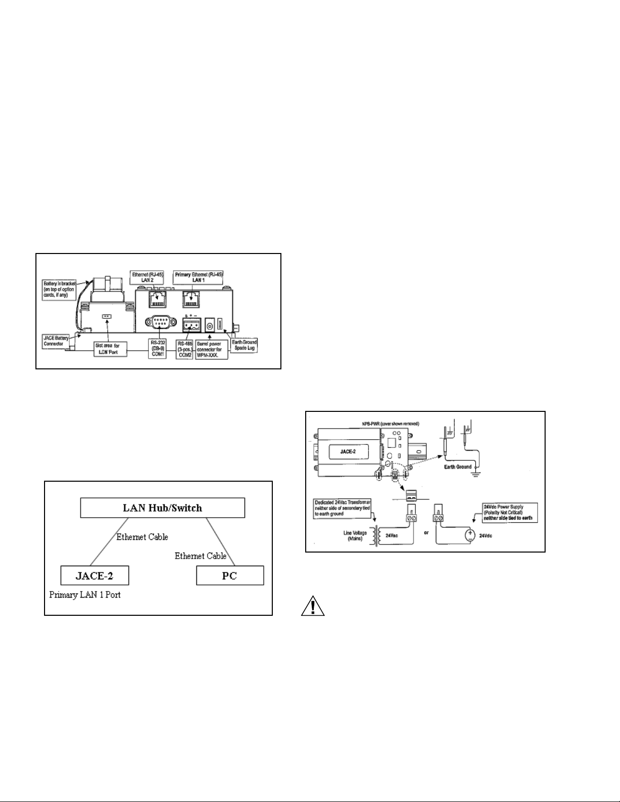
Wire and Cable Connections
Fig. 1. Wire and Cable Connections.
(Reference from JACE-2 Mounting and Wiring Instructions)
• Host Name: WebStat
• Domain Name: WebStat
• DHCP Enabled: false
• IP Address: 10.0.0.1
• Subnet Mask: 255.0.0.0
• Default Gateway: 10.255.255.254
• DNS Server: 10.0.0.3
SECONDARY LAN 2 INTERFACE
• Enabled: false
Grounding
An earth ground spade lug (0.187”) is provided on the base of
the WebStat W7350A for connection to earth ground. For
maximum protection from electrostatic discharge or other
forms of EMI, connect the supplied earth grounding wire to
this lug and a nearby earth ground (see Figure 3). Keep this
wire as short as possible.
Power Wiring
The WebStat W7350A must be powered by an approved 15
Vdc power source. This can be either an external wall mount
AC adapter (WPM-XXX) or the DIN-mount 24 Vac powered
module (NPB-PWR). The WebStat W7350A controller does
not include an on/off switch. To apply power, plug in the power
connector to either the WebStat W7350A (if WPM-XXX) or the
NPB-PWR.
Connecting to LAN/WAN
The following diagram depicts the wiring needed to connect
WebStat to LAN/WAN. It also shows the PC/Laptop that will
be used for initial configuration.
Fig. 2. WebStat Network Connection Diagram.
LAN Hub/Switch can be as simple as a HUB all the way to a
Switch with Router features.
Primary and Secondary interface varies from network to
network. WebStat W7350A1000 comes with the following
default network configuration
PRIMARY LAN 1 INTERFACE
• Enabled: true
Fig. 3. Wiring Diagram for Grounding.
(Reference from JACE-2 Mounting and Wiring Instructions)
CAUTION
Do not connect both the WPM-XXX and NPB-PWR
supplies at the same time, or equipment may be
damaged.
About the Battery
The WebStat W7350A is provided with a custom 10-cell NiMH
battery pack mounted to the unit. This battery allows the
WebStat W7350A to continue through very short power
bumps (a few seconds in duration). If a longer power outage
occurs, the battery provides enough run time for the WebStat
63-2657—01 4
Page 5

WEBSTAT W7350A1000
W7350A to backup data and then shutdown. Typically, this is
one minute. Shutdown occurs automatically after data is
backed up to on-board flash memory.
The WebStat W7350A1000 charges the battery during normal
operation until fully charged. Typically, the charge operation
completes within 18 hours. Following a power outage, the
battery is charged again, as necessary. The power and
battery circuitry is monitored by a station running on the
WebStat W7350A1000 (via the PowerMonitorService). Station
alarms are generated whenever primary power is lost or if the
battery is uncharged or unable to hold a sufficient charge.
The battery should be replaced approximately every three
years or more often if the unit operates in a high temperature
area.
CAUTION
WebStat Comes with built in battery. To increase
the shelf life, the built in battery does not comes
charged. When WebStat is first powered up and
configured, you must initiate a reboot wait for five
minutes before powering it down to avoid loss of
configuration. This procedure has to be followed
only when there is no charge in the battery and
you have made some changes to the
configurations.
However if the battery has charge and the power
goes off, WebStat's built in power management
system initiates a proper shutdown that avoids
loss of configuration. The configuration changes
are written to non-volatile memory once in every
30 minutes. If the above procedure is not followed,
all the changes made since the last Save are lost.
Charging operation completes within 18 Hours.
Connect the Backup Battery
With the cover removed from the WebStat W7350A, locate the
red and black wires coming from the backup battery. On the
end of the wires should be a 2-position connector plug. Insert
the plug into the connector labeled BATTERY on the bottom
board. The red (positive) connection should be the furthest
from the two 30-pin option board connectors.
LED Status
Table 2.
Controllers Color of LED LED Off LED On LED Blinking Location LED’s Activity
Ethernet Port
(Primary)
Ethernet Port
(Secondary)
Heartbeat Yellow N/A N/A Blinks once
Status Green Error condition Whenever the
Green No Ethernet
link is
established
Green No Ethernet
link is
established
Ethernet link is
present, but no
activity on LAN
Ethernet link is
present, but no
activity on LAN
WebStat
W7350A1000
is powered
Ethernet link is
present with
data activity on
LAN
Ethernet link is
present with
data activity on
LAN
per second
N/A Right of the
Top cover Shows the
Top cover Shows the
Right of the
Ethernet
status LEDs
heartbeat
(“BEAT”) LED
status of the
Ethernet link
status of the
Ethernet link
Provides a
CPU machine
status check
5 63-2657—01
Page 6

WEBSTAT W7350A1000
INITIAL WEBSTAT CONFIGURATION
Configuring PC Network
WebStat comes with a default network configuration. The PC/
Laptop that will be used for initial configuration of WebStat
should be configured so that it can communicate with WebStat
using Internet Explorer.
NOTE: PC/Laptop should be running one of Microsoft Win-
dows operating systems. It should have Internet
Explorer 6.0 SP2 or above installed on it.
1. Open the Network and Dial-up Connections window.
(Location: Start > Programs > Accessories > Com-
munications). The window shown in Figure 4 should
appear.
NOTE: The equivalent in Windows XP is “Network Connec-
tions”.
Fig. 4. Network and Dial-up Connections Window.
2. Right click on the appropriate LAN adapter that will be
used for configuring the WebStat W7350A1000 and
click Properties to open the Network Adapter Proper-
ties popup as shown in Figure 5. .
Fig. 5. Properties Page.
3. Double click “Internet Protocol (TCP/IP) to open the
TCP/IP Settings. A popup as shown in Figure 6 should
appear.
63-2657—01 6
Fig. 6. TCP/IP Settings Page.
Page 7

WEBSTAT W7350A1000
IMPORTANT
Provide the following information in the respective fields:
Before making any changes here, note the values in
each field, as this information is needed to restore
the network configuration back to original.
• Use the following IP Address: Selected
• IP Address: 10.0.0.2
• Subnet Mask: 255.0.0.0
• Default Gateway: 10.0.0.254
• DNS Server: 10.0.0.3
4. Click OK on both the pop-ups. Restart the PC/Laptop if
required.
5. Open the command prompt on the PC/Laptop (To
open
the command prompt on the PC/Laptop, click
Start > Programs > Accessories > Command
Prompt or Click Start > Run and type "cmd"
ping WebStat by executing the following command to
check if the communication has been established.
C:\> ping 10.0.0.1
NOTE: In case the ping fails, recheck your network configu-
rations and network connections. If the problem still
persists, take assistance of network administrator.
) and
7 63-2657—01
Page 8

WEBSTAT W7350A1000
Initial Login
To log on to WebStat from the PC/Laptop:
1. Open Internet Explorer in PC/Laptop.
2. In the address bar, type http://10.0.0.1 and press the
Enter key. The browser should open the WebStat login
page as shown in Figure 7.
Fig. 7. WebStat Login Screen.
3. Provide User ID and Password as SysAdmin and
!Sys!Admin correspondingly to login.
4. Click the System tab. This opens the System Configu-
ration screens as shown in Figure 8.
Synchronize with Internet Time Source
Refer to the Initial Login section for steps to login and get to
System Configuration screens.
1. In the Network sub-tab, fill in the network information.
The required information can be obtained from the Net-
work Setup Worksheet (reference the Network Setup
Worksheet in Appendix A) that you have filled by fol-
lowing instructions in the Setup Information Requirements section of this document.
2. On the General sub-tab, in the Time and Date Settings section, check the Use Internet Time Server
checkbox. This enables the Sync Now button.
3. Select appropriate Internet Time server from the list pro-
vided in Time Server Address combo box.
4. Click Save to save the changes made.
NOTE: Sync Now will fail to work if WebStat is on initial
default IP address.
Setup WebStat as Network Time Master
Refer to the Initial Login section for steps to login and get to
System Configuration screens.
1. On the General sub-tab, in the Time and Date Settings section, check the WebStat Network Time Master checkbox. This enables the Sync Now button.
2. Click Save to save the changes made.
Fig. 8. Configuration Window.
Adjusting WebStat System Clock
Refer to the Initial Login section for steps to login and get to
the System Configuration screens.
1. On the General sub-tab, in the Time and Date Set-
tings section, select the appropriate TimeZone and
click Save.
2. If the Time Zone is changed, WebStat will prompt you to
reboot WebStat. Click Yes to proceed. It will take about
5 minutes for WebStat to boot. After 5 minutes, re-login
following the steps given in the Initial Login section.
3. On the General sub-tab, in the Time and Date Set-
tings, adjust the date and time accordingly and click
Save to save the changes made.
NOTE: Sync Now will do nothing if there are no devices
connected to WebStat to manage.
Configuring WebStat Network Interface
Refer to the Initial Login section for steps to login and get to
System Configuration screens.
Fig. 9. Network Settings Window.
1. On the Network tab, enter the network information.
The required information can be obtained from the Network Setup Worksheet (reference Network Setup
Worksheet in Appendix A) that you have filled by fol-
lowing instructions in the Setup Information Requirements section of this document.
2. Click Save to save the network changes. WebStat will
prompt to reboot the system as shown in Figure 10.
63-2657—01 8
Page 9

WEBSTAT W7350A1000
•Port 80 – HTTP Connection to WebStat from Internet
•Port 3011 – Niagarad Platform Daemon access port
NOTE: Network proxy servers can interfere with network
access to WebStat. To minimize the interference, the
proxy server may need re-configuration.
DNS and WINS Support
WebStat supports and uses DNS for sending alarm
information through Electronic Mail. If WebStat is configured
to use static IP address, it would be convenient to register
WebStat’s host name and IP address in a DNS server so that
WebStat can be accessed using Fully Qualified Domain Name
instead of IP address.
WebStat does not support WINS name resolution.
Fig. 10. Reboot Message.
3. Click Yes to reboot the system. WebStat will take about
5 minutes to reboot. Wait for 5 minutes and access it
again. WebStat will start using the new network settings.
4. Restore the network settings of the PC/Laptop. Refer
the original settings that have been suggested in the
Configuring PC Network section.
NOTE: WebStat cannot be accessed from the PC/Laptop
that was used for initial configuration until its network
settings are restored back.
WebStat can be accessed from LAN/WAN as configured.
NOTE: WebStat can synchronize its time with Internet Serv-
ers now. The Sync Now button in the System >
General tab can be used to force time synchronization. Synchronization will succeed only if the DNS is
configured properly and the Internet Time Server is
accessible to WebStat.
INFORMATION FOR NETWORK ADMINISTRATORS
The following information can be required by the network
administrator and/or ISP prior to installation of WebStat. Copy
this page and give it to the network administrator or ISP
contact.
Connection Protocol and IP Address
WebStat supports Ethernet protocol and either Static or DHCP
IP addressing.
Identify the IP addressing type as static or DHCP:
•For static addressing, provide the static IP address.
•For DHCP, the DHCP server assigns the IP address.
Uniform Resource Locator (URL)
WebStat URL is structured as:
scheme://domainname, where:
• Scheme = http
• Domainname = IP address or Fully Qualified
Domain
Name (FQDN) assigned by network administrator or ISP
Electronic Mail Options
WebStat can be configured to send email to a SMTP email
server within the LAN/WAN to which it is connected. If a LAN/
WAN SMTP server is to be used, the SMTP server name is
required. This may be necessary if the local network requires
an email to be delivered only through a network email server.
Consult the site IT System Administrator for the correct
settings.
Ports Used
WebStat web access requires the following network ports to
be open for Internet access:
•Port 1911 – FOX Connection for Trend Charts
Upgrades and Service Packs
Future upgrades and service packs for WebStat will be made
available by download. Specific instructions for downloading
and installing upgrades and service packs will be
communicated as part of the upgrade or service pack
announcement.
9 63-2657—01
Page 10

WEBSTAT W7350A1000
ABOUT WEBSTAT
Use the WebStat to:
•Configure thermostats, schedule them, add them to floor
plans, generate and view trends
•Configure users and define their roles in accessing and
configuring thermostats and WebStat
•Configure a maximum of 12 thermostats on a single
network
•Configure a maximum of 5 schedules on a single network
•Assign up to 12 devices per schedule (one device can be
associated only to one schedule)
•Configure a maximum of 5 trends (each trend having two
thermostat points)
•Store up to 500 samples per trend
•Configure up to 25 user defined alarms
•Store and view up to 200 alarm records
Overview
The Overview screen displays summary information about all
the thermostats within a building. A maximum of 12
thermostats are displayed. Use this screen to view information
related to thermostats.
If you are a user with Contractor privileges, you can also edit
and configure information related to thermostats. You can:
• View Thermostats Details
• Override Schedule Occupancy State
• Cancel Schedule Occupancy Override
• View Alarms
Floor Plans
A Floor Plan is a graphical illustration of a building's layout
coupled with the T7350 thermostat. Floor Plans depict the
placement of thermostats within a building.
There are three occupancy modes:
• Occupied: A period of time when the controlled
environment is considered to be occupied. It
requires a closer control for comfort, health, and
safety. Indicates that the room is occupied.
• Unoccupied: A period of time when the controlled
environment is considered to be unoccupied. It is
used to reduce energy consumption. Indicates that
the room is unoccupied.
• Standby: A period during the normal occupied
period when the space may not be occupied. It is
used for energy saving programs. Indicates that the
room is in the standby mode.
You can:
• View Schedules
• Add and Modify Schedules
• Define Weekly Schedules
• Define Special Events
• Assign Thermostats
• Delete Schedules
Alarms
Use the Alarms tab to view and acknowledge alarms that are
raised on thermostats. You can filter alarms based on
occurrence, acknowledgment status, and priority. You can
setup alarms, define their limits, and prioritize them. You can
also acknowledge alarms and delete acknowledged alarms.
You can configure a maximum of 25 alarms.
You can:
• View Alarms
• Add/Modify Alarms
• Delete Alarm configuration
• Acknowledge Alarms
• Delete Alarms
You can have more than one thermostat in a single floor plan.
All thermostats are configured according to their schedules.
You can:
• Create new Floor Plans
• Modify the existing ones
• Change the images
• Change thermostats
• View different Floor Plans
WebStat can support a maximum of 5 Floor Plans.
Schedules
Schedules define the times and days when an occupancy
event must occur. Schedules are weekly calendars for
occupancy mode changes. Schedules also contain holiday
information. You can have a maximum of five schedules in
WebStat.
63-2657—01 10
Trends
Trends depict the values of points over time in a graphical
format. Use the Trends page to view trends for the selected
points over a period ranging from a day to a year. You can
create and view a maximum of 5 trends.
Trends are plotted for two points, which are read by the same
or two different thermostats over a specified period of time.
For example, outside air temperature and space temperature
can be plotted for a period of one month. You can:
• View Trends
• Add/Modify Trends
• Delete Trends
Page 11

WEBSTAT W7350A1000
Users
Use the Users page to add users, assign thermostats to them
and define their privileges based on their roles. There are
three types of user roles:
• Contractor - This user is the super user of the
system. A Contractor can perform all tasks. At any
point there should be at least one contractor
available in the system.
• Facility Manager - This role represents Building
Engineer who maintains HVAC equipment and
monitors the system with the help of WebStat.
• Tenan t - The user assigned to this role has limited
access to WebStat. A Tenant can access only those
T7350s to which he/she is assigned.
You can:
• View list of Users
• Add/Modify Users
• Delete Users
Thermostats
A thermostat is a device that automatically responds to
temperature changes and activates switches controlling
equipment. It is a circuit that indicates a measured
temperature above or below a particular temperature
threshold or trip point.
Systems
You can use the Systems page only if you have a Contractor's
privileges. Use this page to configure General settings of the
system that include Time and Date settings, new package
installation, SMTP settings, Network settings, and Home Page
settings. You can:
• Configure General Properties
• Configure SMTP Setup Details
• Configure Network Properties
• Configure Home Page Details
CAUTION
It is recommended to use the backup files created
by the current (the one on which you are working
presently) WebStat only. Restoring a backup file
that has been created by a different WebStat (on
which you are not working presently) makes this
WebStat unusable.
Thermostats are used for thermal protection and simple
temperature control systems. They can be combined with
home heating systems, refrigerators, or air conditioners. You
can:
• View list of Thermostats
• Add\Modify Thermostats
• Configure Thermostats
• Discover Thermostats
• Copy Thermostats
• Download Thermostats
• Upload Thermostats
• Delete Thermostats
11 63-2657—01
Page 12

WEBSTAT W7350A1000
APPENDIX A
Network Setup Worksheet
The following information is required to complete the
installation of WebStat. This information is used to configure
WebStat for the network.
NOTE: You may want to take a copy of this worksheet and
use it as a checklist for recording information.
Table 3.
IP Address
Options Static DHCP
IP Address X
WebStat
Setup Data
URL
The URL is required to access WebStat from the Internet or
LAN.
Enter the URL for WebStat. Refer to the Uniform Resource
Locator section for structure.
Fully Qualified Domain Name or IP address
https://
IP Addressing
[ ] Static
[ ] DHCP (Dynamic Host Configuration Protocol)
Setup Data
Based on the selections above, identify the setup data
required. Circle or highlight the column selected and enter the
specific information in Table 3.
Refer to Configuring WebStat Network Interface section for
description
Network Mask X
Default Gateway X
Primary DNS
Server
Local Host Name XX
Local Domain
Name
Refer to Configuring WebStat Network Interface section for
description
WebStat System Settings Details
SMTP Email Server
Email Account ID
Email Account needs
Password
X
XX
Table 4.
Email Account Password
By using this Honeywell literature, you agree that Honeywell will have no liability for any damages arising out of your use or modification to, the
literature. You will defend and indemnify Honeywell, its affiliates and subsidiaries, from and against any liability, cost, or damages, including
attorneys’ fees, arising out of, or resulting from, any modification to the literature by you.
Automation and Control Solutions
Honeywell International Inc. Honeywell Limited-Honeywell Limitée
1985 Douglas Drive North 35 Dynamic Drive
Golden Valley, MN 55422 Toronto, Ontario M1V 4Z9
customer.honeywell.com
® U.S. Registered Trademark
© 2008 Honeywell International Inc.
63-2657—01 HTS Rev. 01-08
 Loading...