

Page 1

Economizer Logic Modules
APPLICATION
W6215, W7215, and W7460 Economizer Logic Modules are
used with an indoor sensor input (ISI), and solid state C7400
Enthalpy Sensors or C7650 Dry Bulb Temperature Sensors.
All models proportion outdoor and return air dampers for
control of free cooling in commercial HVAC equipment. The
W7215B and W7460B are used with an outdoor sensor input
(OSI) along with the ISI.
W6215, W7215, W7460
FOR VENTILATION CONTROL
PRODUCT DATA
FEATURES
• Operates from the space thermostat and an ISI to
provide a totally integrated control system.
• Solid state control package provides accuracy,
reliability and stability.
• Housed in high-impact, glass-fiber reinforced
plastic case.
• Mounts on sheet metal duct or remotely in a
mechanical room. Mounting screws included.
• The W6215 and W7215 are used with Honeywell
Series 62 and Series 72 actuators (respectively).
The W7460 is used with Honeywell M7415 Damper
Actuators.
• Combines minimum and maximum damper position
potentiometers and compressor staging relay
functions with solid state enthalpy or dry bulb
changeover control this control can be tempered
by ISI, and fan cycling.
• Outdoor Sensor input incorporated into logic of
W7215B and W7460B models.
• Shutdown and Air Change can be used with all
models.
• Purge cycling can be used with the W6215A, W7215A
and W7460A models.
• Terminals included for connecting optional S963B1128
Remote Potentiometers for remote minimum and
maximum damper position control.
• LED and relay terminals indicate when free cooling
is available.
• LED indicates when module is in ISI mode.
® U.S. Registered Trademark
Copyright © 2001 Honeywell • All Rights Reserved
Contents
Application ........................................................................ 1
Features ........................................................................... 1
Specifications ................................................................... 2
Ordering Information ........................................................ 2
Installation ........................................................................ 3
Operation .......................................................................... 5
Settings and Adjustments ................................................. 6
Checkout and Troubleshooting ......................................... 26
63- 2544- 3
Page 2

W6215, W7215, W7460 ECONOMIZER LOGIC MODULES
SPECIFICATIONS
Models:
See Table 1.
Dimensions: See Fig. 1.
Electrical Ratings:
Input Voltage: 24 Vac +20%, -15%; 50/60 Hz (Class 2).
Nominal Power Consumption (at 24 Vac, 60 Hz):
W6215A: 12.5 VA.
W7215A, W7460A: 10 VA.
W7215B, W7460B: 10.5 VA.
Relay Contact Rating at 30 Vac (maximum power from class 2
input only): 1.5A run, 3.5A inrush.
Ambient Ratings:
Temperature:
Operating Ambient: -25°F to +125°F (-32°C to +52°C).
Shipping: -25°F to +125°F (-32°C to +52°C).
Humidity (Noncondensing): 5 to 95 percent rh.
Inputs:
Enthalpy (C7400): 2-wire (18,20,22 AWG) connection.
Dry Bulb Temperature (C7650): 2-wire (18,20,22 AWG)
connection.
Discharge Air (C7046): 2-wire (18,20,22 AWG) connection.
Mixed Air (C7150): 2-wire (18,20,22 AWG) connection.
Indoor Sensor: 2-10 Vdc control signal.
Outdoor Sensor (W7215B and W7460B only): 2-10 Vdc
control signal.
Outputs:
W7215: 2-10 Vdc.
W6215: Series 62 (Open/Close/Hold).
24 Vac out (W7215, W6215 only): 25 VA maximum.
Accessories:
32004783-001 Weather Shield Economizers.
4074EJM Bag Assembly. Consists of: Checkout jumper,
620 ohm, 1.2K ohm, 5.6K ohm, and 6.8K ohm checkout
resistors, and 536 ohm, 665 ohm, and 3480 ohm resistors
for use with Honeywell Series 90 Actuators.
C7046A Discharge Air Temperature Sensor.
C7150B Mixed Air Temperature Sensor.
C7400 Solid State Enthalpy Sensor.
C7650 Dry Bulb Temperature Sensor.
S963B1128 Remote Potentiometer to provide remote control
of damper minimum or maximum position.
ST6008 Energy Management Timer for occupied/unoccupied
control.
Approvals:
Underwriters Laboratories Inc. listed: Meets UL873
plenum requirements.
3/4 (19)
1
(25)
24VAC
TR Hot
BC
A
Maximum
Position
Open
Free Cool
Mininum
Position
Closed
6
2
ISI
Set Pt
ISI
50%
0%
Exhaust
Set Pt
Exhaust
100%
TR1
Com
+
D
So
+
Sr
5
1
2
3
4
T
T1
P
Q
AQ
+
AQ1
10
SD
SD1
AC
AC1
PC
PC1
8-5/8
P1
(219)
Q1
–
1
(25)
1-9/16
(40)
+
–
24VAC
Hot
24VAC
Com
2-10V
OUT
Free
Cool
Unit
Control
Exhaust
Fan
Indoor
Fan
W7215A
5-3/4 (146)
Fig. 1. W6215,W7215,W7460 dimensions
in in. (mm). [W7215A shown]
M11788A
ORDERING INFORMATION
When purchasing replacement and modernization products from your TRADELINE® wholesaler or distributor, refer to the
TRADELINE® Catalog or price sheets for complete ordering number.
If you have additional questions, need further information, or would like to comment on our products or services, please write or
phone:
1. Your local Home and Building Control Sales Office (check white pages of your phone directory).
2. Home and Building Control Customer Relations
Honeywell, 1885 Douglas Drive North
Minneapolis, Minnesota 55422-4386
In Canada—Honeywell Limited/Honeywell Limitée, 35 Dynamic Drive, Scarborough, Ontario M1V 4Z9.
International Sales and Service Offices in all principal cities of the world. Manufacturing in Australia, Canada, Finland, France,
Germany, Japan, Mexico, Netherlands, Spain, Taiwan, United Kingdom, U.S.A.
63-2544—3 2
Page 3

W6215, W7215, W7460 ECONOMIZER LOGIC MODULES
0
Table 1. W6215, W7215, and W7460 Economizer Models.
For Use
Model
W6215A Honeywell Series 62 C7150B or C7046A Sensor No Adjustable Yes
W7215A Honeywell Series 72 C7150B or C7046A Sensor No Adjustable Yes
W7215B Honeywell Series 72 C7150B or C7046A Sensor Yes Fixed No
W7460A Honeywell M7415 C7150B or C7046A Sensor No Adjustable Yes
W7460B Honeywell M7415 C7150B or C7046A Sensor Yes Fixed No
NOTE: All models include minimum and maximum position potentiometers, setpoint for enthalpy or dry-bulb, and ISI setpoint.
with Actuator
Discharge Air
Temperature Input
Outdoor Sensor
Input (OSI) Setpoint
Exhaust
Fan Setpoint Purge
INSTALLATION
When Installing this Product...
1.
Read these instructions carefully. Failure to follow
them could damage the product or cause a hazardous
condition.
2.
Check the ratings given in the instructions and on the
product to make sure the product is suitable for your
application.
3. Installer must be a trained, experienced service
technician.
4. After installation is complete, check out product
operation as provided in these instructions.
CAUTION
Electrical Shock or Equipment Damage Hazard.
Can shock individuals or short equipment
circuitry.
Disconnect power supply before installation.
IMPORTANT
Location and Mounting
All wiring must agree with applicable codes,
ordinances and regulations.
OUTDOOR AIR SENSING
1.
Mount sensor in any orientation that exposes it to freely
circulating air and protects it from rain, snow, and direct
sunlight.
2. Connect it to the S
RETURN AIR SENSING
1.
Ensure differential enthalpy control has a second
sensor in the return air duct.
2. Connect this sensor to the S
W6215, W7215, or W7460.
and + terminals of the device.
O
and + terminals of the
R
W6210 A 1003
W6215, W7215, W7460 Economizer Logic Module
W6215, W7215, and W7460 Logic Modules mount directly on
a sheet metal duct or panel. When planning the installation,
allow enough clearance for maintenance and service. Mount
device in a location protected from rain, snow, and direct
sunlight. Secure device to sheet metal using the three supplied
mounting screws, see Fig. 2.
NOTE: See Fig. 3 for representative locations of connected
system devices.
C7400 Enthalpy Sensor and
C7650 Dry Bulb Temperature Sensor
W6215,W7215,W7460 Logic Modules accept signals from
either the C7400 Enthalpy Sensor or the C7650 Dry Bulb
Temperature Sensor. The wiring is the same for either sensor.
IMPORTANT
When using differential sensing, both sensors must
be of the same type (enthalpy or dry bulb).
M1179
Fig. 2. Mounting W6215, W7215, W7460 on sheet metal.
Indoor Sensor Input
The ISI can be any sensor that provides a 2-10 Vdc output.
The ISI modulates the outdoor damper to provide ventilation
based on occupancy. The designer determines contaminants
to monitor, selects appropriate sensor, determines the sensor
threshold, and adjusts the ISI potentiometer accordingly. The
ISI LED lights when the ISI signal is above setpoint. Mount the
sensor according to the manufacturer specifications. If not
available, use the following guidelines:
1. Mount sensor in an area with unobstructed air circulation.
2. Connect it to the AQ
W7215, or W7460 (see Wiring section for details).
3. Adjust the ISI potentiometer setpoint to correspond to
ISI voltage output at the threshold.
IMPORTANT
Ensure proper polarity of sensor connections.
Incorrect polarity negates the sensor signal.
3 63-2544—3
and AQ1 terminals of the W6215,
Page 4

W6215, W7215, W7460 ECONOMIZER LOGIC MODULES
Outdoor Sensor Input (W7215B and W7460B only)
The OSI sensor can be any sensor that provides a 2-10 Vdc
output. Mount the sensor according to the manufacturer
specifications. If not available, use the following guidelines:
1. Mount sensor in an area with unobstructed air circulation
that is protected from rain, snow, and direct sunlight.
DISCHARGE
AIR SENSOR
INDOOR
FAN
DIRECT
EXPANSION
COIL
W6215,
W7215,
OR
W7460
C7046A
DISCHARGE
AIR
2
C7150B
MIXED AIR
SENSOR
C7400
ENTHALPY
SENSOR
IMPORTANT
Ensure proper polarity of sensor connections.
Incorrect polarity negates the sensor signal.
2. Connect it to the OA
or W7460B (see Wiring section for details).
and OA1 terminals of the W7215B,
3. Adjust the OSI potentiometer setpoint to correspond to
OSI sensor voltage output at the threshold.
SPACE
2
SERIES
62 OR 72
ACTUATOR
1
THERMOSTAT
1
C7400
OUTDOOR
AIR
SENSOR
INDOOR
AIR
SENSOR
ENTHALPY
SENSOR
OUTDOOR
AIR
FOR DIFFERENTIAL ENTHALPY, THE TWO C7400
1
ENTHALPY SENSORS ARE CONNECTED TO THE
W6215/W7215/W7460 ECONOMIZER CONTROL—ONE
IS MOUNTED IN RETURN AIR, AND THE OTHER IS
MOUNTED IN OUTDOOR AIR. DIFFERENTIAL
ENTHALPY CONTROL PROVIDES GREATER
ENERGY SAVINGS THAN SINGLE ENTHALPY.
2
USE EITHER MIXED AIR SENSOR OR DISCHARGE
AIR SENSOR, NOT BOTH.
Fig. 3. Representative locations of connected Economizer system devices.
Wiring
CAUTION
Electrical Shock or Equipment Damage Hazard.
Can shock individuals or short equipment
circuitry.
Disconnect power supply before installation.
IMPORTANT
1. All wiring must comply with applicable local codes,
ordinances and regulations.
2. Refer to Fig. 6 through 25 for typical wiring diagrams.
3. Refer to Table 2 for a list of the wiring diagrams and
corresponding Figure numbers in this document.
4. All device inputs and outputs must be 24 Vac Class 2.
NOTE: All connections with label designation ending in 1
(examples: TR1, T1, P1, Q1, AQ1) are ac/dc
common connections.
EXHAUST
FAN
RETURN AIR
EXHAUST AIR
M11816
Optional Applications
Remote Minimum Position Control
Remote control of outdoor air dampers is desirable when
requiring temporary additional ventilation. One potentiometer
controls the damper minimum position, another potentiometer
controls the damper maximum position. The addition of
S963B1128 Remote Potentiometers allows occupants to open
or close the dampers beyond minimum position for modified
ventilation. Connect the potentiometers as shown in Fig. 4.
IMPORTANT
Free Cool Timing
The Free Cool contacts close while the logic module operates
free cooling. Connecting a timer to these contacts allows
tracking of the free cooling usage time.
The minimum position signal takes priority to the
maximum position signal. With the maximum set
below the minimum, the logic module signals the
actuator to maintain the minimum position.
63-2544—3 4
Page 5

W6215, W7215, W7460 ECONOMIZER LOGIC MODULES
Table 2. Applicable Wiring Diagrams.
Logic Module Actuator Enthalpy Changeover Figure Comments
W6215A Honeywell Series 62 Single 8 Single-stage cooling system.
Single or Differential 9 Two-stage cooling system.
W7215A Honeywell Series 72 Single 10 Single-stage cooling system.
Single or Differential 11 Two-stage cooling system.
12 T775 controller.
Honeywell Series 90 n/a 6 Add Q7230 Interface Module.
W7215B Honeywell Series 72 Single 13 Single-stage cooling system.
Single or Differential 14 Two-stage cooling system.
15 T775 controller.
W7460A Honeywell M7415 Single 16 Single-stage cooling system.
Single or Differential 17 Two-stage cooling system.
W7460B Honeywell M7415 Single 18 Single-stage cooling system.
Single or Differential 19 Two-stage cooling system.
ALL n/a n/a 20 W7100 controller.
25 W973 Logic Panel.
4 S963 remote damper control.
Parallel Wiring
W6215 Honeywell Series 62 Single or Differential 21 Honeywell Series 62 Direct Coupled Actuators.
W7215A Honeywell Series 72 22 Honeywell Series 72 Direct Coupled Actuators.
23 Honeywell Series 72 Modutrol Motors.
Honeywell M7415 24 M7415 Motors.
OPERATION
The purpose of the economizer is to use outdoor air for
cooling, whenever possible, to reduce compressor operation.
When wired as shown in Fig. 6 through 25, the logic module
responds to the cooling thermostat signal. This system
uses C7400 Solid State Enthalpy Changeover Sensor(s) or
C7650 Dry Bulb Temperature Sensor(s). The C7400 responds
to both dry bulb temperature and humidity, allowing use of
outdoor air at higher temperatures for free cooling when
humidity is low. The C7650 responds only to dry bulb
temperature; use only in dry, arid climates.
The logic module functions as a true first stage of cooling
providing maximum fuel economy during the cooling cycle.
It automatically locks out free cooling during heating; holding
the outdoor air damper at the minimum position setting.
The logic module can operate as either a basic free cooling
controller, or it can incorporate additional functions. Tables 3
and 5 detail the input/output (I/O) logic of the module. Certain
functions—Purge, Shutdown, and Air Change—override
others, see Table 3. When these functions are all off, the logic
module energizes the Unit Control and Indoor Fan contacts,
operating according to Table 5.
Purge (W6215A, W7215A, and W7460A only)
When terminals PG and PG1 connect through relay contacts
or a jumper:
1. Outdoor damper drives fully closed.
2.
Exhaust fan turns on.
S963B1128 REMOTE
OPEN
MINIMUM
POSITION
ADJUSTMENT
CW
MAXIMUM
POSITION
ADJUSTMENT
CW
W6215/W7215/W7460 ECONOMIZER
P1
P
Q1
Q
Fig. 4. S963B1128 Remote Potentiometer used with
W6215, W7215, W7460 for remote damper control.
POTENTIOMETER
R
CCW
OPEN
135 OHM
S963B1128 REMOTE
POTENTIOMETER
CCW
OPEN
135 OHM
CW
CLOSE
R
CW
CLOSE
M11796A
WB
WB
5 63-2544—3
Page 6

W6215, W7215, W7460 ECONOMIZER LOGIC MODULES
Table 3. W6215, W7215, W7460 Economizer Purge,
Shutdown, and Air Change I/O Logic.
INPUTS OUTPUTS
Purge
Shut-
a
down
Air
Change Damper
Unit
Control
Indoor
Fan Exhaust
On - - Fully Closed Off Off On
Off On - Off
Off On Fully Open On On
a
Purge present only on W6215A, W7215A, and W7460A.
Shutdown
One contact closure shuts down all systems. When terminals
SD and SD1 connect through relay contacts or a jumper:
1.
Outdoor damper drives fully closed.
2.
Exhaust fan turns off.
3. Indoor fan turns off.
Air Change
When terminals AC and AC1 connect through relay contacts
or a jumper:
1. Outdoor damper drives fully open.
2. Exhaust fan turns on.
3. Indoor fan turns on.
NOTE: With Purge, Shutdown, and Air Change de-
energized, Exhaust will be de-energized unless the
signal exceeds the exhaust fan setpoint; other logic
module functions remain unaltered.
SETTINGS AND ADJUSTMENTS
Potentiometers with screwdriver adjustment slots, located on
the device face, provide adjustments for several parameters
(see Fig. 5 for locations on device):
— ISI setpoint.
— OSI setpoint (W7215B and W7460B only).
— Minimum damper position.
— Maximum damper position.
— Enthalpy changeover.
— Exhaust setpoint (W6215A, W7215A and W7460A only).
Indoor Sensor Input Setpoint
The logic module modulates the outdoor damper to provide
ventilation based on the 2-10 Vdc ISI. With no cooling signal,
the ISI overrides the outdoor air damper when ventilation
requires outdoor air.
Outdoor Sensor Input Setpoint (W7215B and W7460B only)
The OSI logic operates from a 2-10 Vdc sensor signal. The
operation of these logic modules is slightly different from the
other models, see Table 4.
Table 4. W7215B and W7460B OSI Operation.
OSI ISI Actuator OSI LED Alarm
Below set Below set
Above set
Modulates
Modulates
Modulates
Above set Below set Fully closed On Off
Above set
a
Modulation based on signal from mixed air sensor.
b
With ISI signal greater than mixed air sensor signal:
Modulates
Modulation, based on ISI signal, between minimum and
maximum positions.
c
With ISI signal less than mixed air sensor signal:
Modulation, based on mixed air sensor signal, between:
M7215B: Minimum and full open positions
M7460B: Minimum and maximum positions.
d
Modulation based on mixed air sensor signal;
connect to energize warning light, audio alarm, or air cleaner.
a
Off Off
b
c
d
On On
Alarm
terminals
Table 5. W6215, W7215, W7460 Economizer I/O Logic.
INPUTS OUTPUTS
a
Y1
b
Y2
b
Damper
Compressor
On Off On Off
Modulating
c
On Off
ISI
Below set
(ISI LED Off)
Enthalpy
Outdoor Return 1 2
High (Free Cooling LED Off) Low On On Minimum position On On
Low (Free Cooling LED On) High On On
On Off Off Off
Above set
(ISI LED On)
High (Free Cooling LED Off) Low On On
On Off On Off
Low (Free Cooling LED On) High On On
Modulating
Modulating
d
e
On On
On Off
On Off Off Off
a
For single enthalpy control, the module compares outdoor enthalpy to the ABCD setpoint.
b
If both stages of cooling are off, the system is off and the damper is at: • Minimum position if ISI is below setpoint.
c
W6215, W7460: Modulation, based on the mixed air sensor signal, between minimum and maximum positions.
W7215: Modulation, based on the mixed air sensor signal, between minimum and full-open positions.
d
Modulation, based on the ISI, between minimum and maximum positions.
e
Modulation, based on the greater of ISI and mixed air sensor signals, between minimum and either maximum position (ISI) or
• Modulating if ISI is above setpoint.
fully open (mixed air signal).
NOTE: Each sensor has it’s own setpoint for threshold and LED indication.
63-2544—3 6
Page 7

W6215, W7215, W7460 ECONOMIZER LOGIC MODULES
T
24VAC
24VAC
Hot
24VAC
Com
+
2-10V
OUT
–
Free
Cool
Unit
Control
Exhaust
Fan
Indoor
Fan
LED LIGHTS WHEN EXHAUST IS ON
W7215A
TR Hot
BC
A
Mininum
Position
Open
Free Cool
Maximum
Position
Closed
2
ISI
Set Pt
ISI
50%
0%
Exhaust
Set Pt
Exhaust
TR1
Com
+
D
So
+
Sr
5
1
2
3
4
T
T1
P
P1
Q
Q1
AQ
6
+
AQ1
–
Q
10
SD
SD1
AC
AC1
Q
PG
PG1
Q
100%
Fig. 5. Potentiometer and LED locations.
ENTHALPY
CHANGEOVER
SETPOINT
MINIMUM
DAMPER
POSITION
SETTING
LED LIGHTS
WHEN
OUTDOOR
AIR IS
SUITABLE
FOR FREE
COOLING
MAXIMUM
DAMPER
POSITION
SETTING
INDOOR AIR
SENSOR
SETPOINT
LED LIGHTS
WHEN INDOOR
SENSOR INPU
IS ABOVE
SETPOINT
EXHAUST
FAN
SETPOINT
M11787A
NOTE: Make minimum position adjustments with at least a
10°F [6°C] temperature difference between outdoor
and return air.
1. Calculate the appropriate mixed air temperature, see
Equation 1.
2. Disconnect mixed air sensor from terminals T and T1.
3. Ensure that either the factory-installed jumper is in
place across terminals P and P1 or, of remote damper
position is required, that it is wired according to Fig. 4
and turned fully clockwise.
4.
Connect 24 Vac across terminals TR and TR1.
5. Carefully adjust the potentiometer on the face of the
device with a small screwdriver until the mixed air
temperature reaches the calculated value.
NOTE: Ensure that the sensed air is well mixed.
Equation 1. Formula to aid in minimum position
adjustment.
TOOA×()TRRA×()+ TM=
Where:
TO = Outdoor air temperature
OA = Percent of outdoor air
= Return air temperature
T
R
RA = Percent of return air
= Resulting mixed air temperature
T
M
IMPORTANT
This procedure requires use of a quality thermometer
capable of reading to 0.5°F [0.25°C].
Adjusting Minimum and Maximum Positions
The minimum position potentiometer maintains the minimum
outdoor air flow into the building during occupied period. The
maximum position potentiometer allows the installer to limit
the amount of outdoor air flow into the building, when the ISI
overrides the mixed air sensor. Setting the maximum position
of the damper prevents the introduction of large amounts of
hot or cold air into the space.
IMPORTANT
NOTES:
Minimum Position Adjustment
For detailed assistance in minimum position selection
reference the Economizer Application Guide (form 63-8594)
Ventilation section. The following provides basic guidelines for
minimum position selection and adjustment:
IMPORTANT
With the maximum position set below the minimum
position, the minimum position overrides the
maximum position (negating most functions of the
logic module, as the damper cannot move).
— When the mixed air sensor takes control, it
overrides the maximum position potentiometer.
— If mixed air temperature drops to 40°F, the mixed
air sensor overrides the ISI and closes the damper
to minimum position to protect from freezing the
hot or chilled water coils. Control returns to normal
once the mixed air temperature rises to 43°F.
Adjust the minimum position potentiometer to allow
the minimum amount of outdoor air, as required by
local codes, to enter the building.
NOTE: The following sample calculation uses only
Fahrenheit temperature.
EXAMPLE: Assume local codes require 10% outdoor air
during occupied conditions, outdoor air is 60°F
and return air is 75°F. Under these conditions,
what is the temperature of the mixed air?
0.1 60°F×()0.9 75°F×()+ 6.0°F 67.5°F+ 73.5°F==
Mixed air will be 73.5°F when OA is 60°F and RA is 75°F with
10 percent outdoor air entering the building.
Maximum Position Adjustment
1. Disconnect mixed air sensor from terminals T and T1
and short terminals T and T1.
2. Make sure either the factory-installed jumper is in place
across terminals Q and Q1 or, if remote damper position
is required, that it is wired according to Fig. 4 and turned
fully clockwise.
3. Connect 24 Vac across terminals TR and TR1.
4. Adjust the potentiometer on the face of the device with a
screwdriver for desired maximum position.
Enthalpy Changeover
Outdoor Enthalpy Changeover Setpoint
The outdoor enthalpy changeover setpoint returns the outdoor
air damper to minimum position when enthalpy rises above its
setpoint. Enthalpy setpoint scale markings, located in the
device, are A, B, C, and D. See Fig. 7 for the corresponding
control point. The factory-installed 620-ohm jumper must be in
place across terminals S
and +.
R
7 63-2544—3
Page 8

W6215, W7215, W7460 ECONOMIZER LOGIC MODULES
85
100
105
110
)
0
)
Differential Enthalpy Changeover Setting
Differential enthalpy control uses two C7400 Enthalpy
Sensors connected to one logic module. The logic module
compares outdoor air to return air instead of to a setpoint as it
does for single enthalpy. Turn the setpoint potentiometer fully
clockwise to the D setting. The logic module selects the lower
enthalpy air (return or outdoor) for cooling; for example, when
outdoor air has lower enthalpy than return air, the outdoor air
damper opens to bring in outdoor air for free cooling.
Exhaust Setpoint
Except for Purge, Shutdown, and Air Change, the exhaust
setpoint determines when the exhaust fan runs based on the
damper position. When the ISI call for exhaust comes, the
module provides a 45 ±15 second delay before exhaust fan
activation. This delay allows the damper to reach the
appropriate position to avoid unnecessary fan overload.
Adjustable Exhaust Setpoint (W6215A, W7215A, and W7460A only)
The W6215A, W7215A, and W7460A Logic Modules have an
adjustable setpoint. This potentiometer allows the installer to
set the exhaust setpoint at an actual damper position
percentage open from fully closed.
Fixed Exhaust Setpoint (W7215B and W7460B)
The W7215B and W7460B Logic Modules have a fixed
exhaust setpoint. The logic module uses an exhaust setpoint
of 60 percent. When the damper reaches 60 percent open
(from fully closed), the logic module calls for exhaust.
W7215A
HONEYWELL
SERIES 90
ACTUATOR
(ML9175,
ML9185,
M9175,
M9185)
1
M11903A
W
R
1
B
USE 1/2 WATT, 1% RESISTORS OF
SPECIFIED OHM RATINGS (INCLUDED
IN 4074EJM RESISTOR KIT). FOR
MOD IV MOTORS, THE Q7230 MODULE
CAN REPLACE THE RESISTORS.
665
Ohms
3480
Ohms
536
Ohms
Fig. 6. W7215A used with Honeywell Series 90 Actuator.
24 VAC HOT
24 VAC COM
+
2-10V
OUT
–
TR
TR1
CONTROL
12 14 16 18 20 22 24 26 28 30 32 34 36 38 40 42 44 46
CURVE
A
B
C
D
CONTROL POINT
APPROX. °F (°C)
AT 50% RH
73 (23)
70 (21)
67 (19)
63 (17)
ENTHALPY—BTU PER POUND DRY AIR
60
(16)
55
(13)
B
50
C
(10)
45
D
(7)
40
(4)
35
(2)
75
(24)
70
(21)
100
90
65
(18)
80
70
A
80
(27)
60
50
(29)90(32)95(35)
RELATIVE HUMIDITY (%)
40
30
(38)
20
(41)
(43
10
35
40
45
50
(2)
(4)
(7)
(10)
55
(13)
APPROXIMATE DRY BULB TEMPERATURE—°F (°C)
Fig. 7. W6215, W7210, and W7460/C7400 performance characteristics for enthalpy changeover settings.
63-2544—3 8
60
(16)
65
(18)
70
(21)
A
B
C
D
105
75
80
(24)
85
(27)
(29)90(32)95(35)
100
(38)
(41)
(43
M11806
11
Page 9

HONEYWELL
SERIES 62
ACTUATOR
(ML6275,
ML6285,
M6275,
M6285)
24 VAC HOT
24 VAC COM
CLOSE
OPEN
W6215A
W6215, W7215, W7460 ECONOMIZER LOGIC MODULES
TR1
TR
C7400
OUTDOOR
+
S
O
+
S
R
620 OHM
RESISTOR
5
6
9
+
AIR
ENTHALPY
S
SENSOR
500 OHM
W2
1S
OPEN
WIPER
CLOSED
5
Y1
Y2
4
1S1
MINIMUM POSITION
ADJUSTMENT
MAXIMUM
FREE
POSITION
COOL
ADJUSTMENT
UNIT
CONTROL
EXHAUST
FAN
INDOOR
FAN
T6031 AMBIENT
W
LOCKOUT
CONTROL
R
50 F SETPOINT
1K
2K
1
3
T
P
Q
AQ
SD
AC
PG
2
4
T1
P1
Q1
AQ1
SD1
AC1
PG1
C7150B MIXED
AIR OR
C7046A
DISCHARGE
AIR SENSOR
2-10 VDC
INDOOR AIR
SENSOR
+
SHUT DOWN
AIR CHANGE
PURGE
Y1
W2
9
8
UNOCCUPIED
ST6008
TIMER
OCCUPIED
C
COOL 1
HEAT 2
2
HEAT 1
FAN
DELAY
RELAY
FAN
M11803A
3
L2
L1
(HOT)
1
W1
G
RH
RC
7
X
T7300 OR T874
THERMOSTAT
1
POWER SUPPLY. PROVIDE DISCONNECT MEANS AND OVERLOAD
PROTECTION AS REQUIRED.
2
ACTUATOR SPRING-RETURNS CLOSED WHEN FAN IS NOT RUNNING.
3
ENSURE THAT TRANSFORMER IS SIZED TO HANDLE THE EXTRA
LOAD OF THE ECONOMIZER AND ACTUATOR.
1S IS AN ELECTRONIC SWITCH THAT CLOSES WHEN POWERED
4
BY A 24 VAC INPUT.
5
THE COMMON FOR THE W6215A IS DIFFERENT THAN THE
COMMON (WIPER) FOR THE SERIES 62 ACTUATORS. BE SURE
TO CONNECT EACH TO A DIFFERENT CIRCUIT.
W1
FDR
G
FDR
R
HVAC EQUIPMENT
TERMINAL STRIP
6
FACTORY INSTALLED 620 OHM, 1 WATT, 5% RESISTOR SHOULD NOT BE
REMOVED. DIFFERENTIAL ENTHALPY NOT RECOMMENDED FOR USE
WITH SINGLE-STAGE COOLING SYSTEMS OR SINGLE-STAGE COOLING
THERMOSTATS.
7
FOR T7300 ONLY.
8
FOR T7300, USE CONTACTS A1 AND A2 INSTEAD OF THE TIMER.
9
FOR TWO-STAGE THERMOSTATS ONLY.
Fig. 8. W6215A used in single-stage cooling system with single enthalpy changeover and Honeywell Series 62 Actuator.
9 63-2544—3
Page 10

W6215, W7215, W7460 ECONOMIZER LOGIC MODULES
W6215A
HONEYWELL
SERIES 62
ACTUATOR
(ML6275,
ML6285,
M6275,
M6285)
24 VAC HOT
24 VAC COM
CLOSE
OPEN
TR1
TR
C7400
OUTDOOR
+
S
O
+
S
R
620 OHM
RESISTOR
5
6
+
AIR
ENTHALPY
S
SENSOR
500 OHM
Y1
Y2
1S
OPEN
WIPER
CLOSED
5
4
1S1
MINIMUM POSITION
ADJUSTMENT
FREE
COOL
UNIT
CONTROL
EXHAUST
FAN
INDOOR
FAN
MAXIMUM
POSITION
ADJUSTMENT
1K
2K
1
3
T
P
Q
AQ
SD
AC
PG
2
4
T1
P1
Q1
AQ1
SD1
AC1
PG1
C7150B MIXED
AIR OR
C7046A
DISCHARGE
AIR SENSOR
T6031 AMBIENT
LOCKOUT
CONTROL
50 F SETPOINT
2-10 VDC
INDOOR AIR
+
SENSOR
SHUT DOWN
AIR CHANGE
PURGE
C
Y1
Y2
W
R
COOL 1
COOL 2
UNOCCUPIED
8
ST6008
TIMER
OCCUPIED
W2
W1
G
RH
RC
7
1
2
3
4
X
T7300 OR T874
THERMOSTAT
POWER SUPPLY. PROVIDE DISCONNECT MEANS AND OVERLOAD
PROTECTION AS REQUIRED.
ACTUATOR SPRING-RETURNS CLOSED WHEN FAN IS NOT RUNNING.
ENSURE THAT TRANSFORMER IS SIZED TO HANDLE THE EXTRA
LOAD OF THE ECONOMIZER AND ACTUATOR.
1S IS AN ELECTRONIC SWITCH THAT CLOSES WHEN POWERED
BY A 24 VAC INPUT.
Fig. 9. W6215A used in two-stage cooling system with a Honeywell Series 62 Actuator.
63-2544—3 10
2
HEAT 2
HEAT 1
FAN
DELAY
RELAY
FAN
3
L2
L1
(HOT)
1
W2
W1
FDR
G
FDR
R
HVAC EQUIPMENT
TERMINAL STRIP
5
THE COMMON FOR THE W6215A IS DIFFERENT THAN THE COMMON
(WIPER) FOR THE SERIES 62 ACTUATORS. BE SURE TO CONNECT EACH
TO A DIFFERENT CIRCUIT.
FACTORY INSTALLED 620 OHM, 1 WATT, 5% RESISTOR SHOULD BE REMOVED
6
ONLY WHEN A C7400 ENTHALPY SENSOR IS ADDED TO SR AND + FOR
DIFFERENTIAL ENTHALPY.
7
FOR T7300 ONLY.
8
FOR T7300, USE CONTACTS A1 AND A2 INSTEAD OF THE TIMER.
M11800A
Page 11

HONEYWELL
SERIES 72
ACTUATOR
(ML7275,
ML7285,
ML7295A,C
M7275,
M7285)
W7215A
24 VAC HOT
24 VAC COM
W6215, W7215, W7460 ECONOMIZER LOGIC MODULES
TR1
TR
C7400
OUTDOOR
+
S
O
+
S
R
620 OHM
RESISTOR
5
6
9
+
AIR
ENTHALPY
S
SENSOR
W2
1S
+
+
2-10 VDC
OUT
––
5
Y1
Y2
W
R
4
1S1
MINIMUM POSITION
ADJUSTMENT
FREE
COOL
UNIT
CONTROL
EXHAUST
FAN
INDOOR
FAN
MAXIMUM
POSITION
ADJUSTMENT
T6031 AMBIENT
LOCKOUT
CONTROL
50° F SETPOINT
1K
2K
1
Q
AQ
SD
AC
PG
2
4
3
C7150B MIXED
T1
T
P1
P
Q1
AQ1
SD1
AC1
PG1
AIR OR
C7046A
DISCHARGE
AIR SENSOR
–
2-10 VDC
INDOOR
+
AIR SENSOR
SHUT DOWN
AIR CHANGE
PURGE
C
Y1
W2
9
COOL 1
HEAT 2
8
ST6008
TIMER
UNOCCUPIED
OCCUPIED
2
HEAT 1
FAN
DELAY
RELAY
FAN
3
L2
L1
(HOT)
M11804A
1
W1
G
RH
RC
7
1
2
3
4
5
X
T7300 OR T874
THERMOSTAT
POWER SUPPLY. PROVIDE DISCONNECT MEANS AND OVERLOAD
PROTECTION AS REQUIRED.
ACTUATOR SPRING-RETURNS CLOSED WHEN FAN IS NOT RUNNING.
ENSURE THAT TRANSFORMER IS SIZED TO HANDLE THE EXTRA
LOAD OF THE ECONOMIZER AND ACTUATOR.
1S IS AN ELECTRONIC SWITCH THAT CLOSES WHEN POWERED
BY A 24 VAC INPUT.
FOR THE ML7295A,C, USE THE 4-20mA MODEL ACTUATOR. THESE
MODELS HAVE 500 OHM INPUT IMPEDENCE THAT ALLOWS THE
ACTUATOR TO ACCEPT A 2-10 VDC SIGNAL.
W1
FDR
G
FDR
R
HVAC EQUIPMENT
TERMINAL STRIP
6
FACTORY INSTALLED 620 OHM, 1 WATT, 5% RESISTOR SHOULD NOT BE
REMOVED. DIFFERENTIAL ENTHALPY NOT RECOMMENDED FOR USE
WITH SINGLE-STAGE COOLING SYSTEMS OR SINGLE-STAGE COOLING
THERMOSTATS.
7
FOR T7300 ONLY.
8
FOR T7300, USE CONTACTS A1 AND A2 INSTEAD OF THE TIMER.
9
FOR TWO-STAGE THERMOSTATS ONLY.
Fig. 10. W7215A used in single-stage cooling system with single enthalpy changeover and Honeywell Series 72 Actuator.
11 63-2544—3
Page 12

W6215, W7215, W7460 ECONOMIZER LOGIC MODULES
W7215A
HONEYWELL
SERIES 72
ACTUATOR
(ML7275,
ML7285,
ML7295A,C
M7275,
M7285)
24 VAC HOT
24 VAC COM
TR1
TR
C7400
OUTDOOR
S
+
O
S
R
620 OHM
+
RESISTOR
5
6
+
AIR
ENTHALPY
S
SENSOR
1S
+
–
5
Y1
Y2
+
2-10V
OUT
–
4
1S1
MINIMUM POSITION
ADJUSTMENT
FREE
COOL
UNIT
CONTROL
EXHAUST
FAN
INDOOR
FAN
MAXIMUM
POSITION
ADJUSTMENT
1K
2K
1
T
Q
AQ
SD
AC
PG
2
4
3
T1
P1
P
Q1
AQ1
SD1
AC1
PG1
C7150B MIXED
AIR OR
C7046A
DISCHARGE
AIR SENSOR
T6031 AMBIENT
LOCKOUT
CONTROL
50° F SETPOINT
2-10 VDC
–
INDOOR
+
AIR SENSOR
SHUT DOWN
AIR CHANGE
PURGE
C
Y1
Y2
W
R
UNOCCUPIED
ST6008
TIMER
COOL 1
COOL 2
OCCUPIED
8
W2
W1
G
RH
RC
7
1
2
3
4
X
T7300 OR T874
THERMOSTAT
POWER SUPPLY. PROVIDE DISCONNECT MEANS AND OVERLOAD
PROTECTION AS REQUIRED.
ACTUATOR SPRING-RETURNS CLOSED WHEN FAN IS NOT RUNNING.
ENSURE THAT TRANSFORMER IS SIZED TO HANDLE THE EXTRA
LOAD OF THE ECONOMIZER AND ACTUATOR.
1S IS AN ELECTRONIC SWITCH THAT CLOSES WHEN POWERED
BY A 24 VAC INPUT.
Fig. 11. W7215A used in two-stage cooling system with Honeywell Series 72 Actuator.
63-2544—3 12
2
HEAT 2
HEAT 1
FAN
DELAY
RELAY
FAN
3
L2
L1
(HOT)
1
W2
W1
FDR
G
FDR
R
HVAC EQUIPMENT
TERMINAL STRIP
5
FOR THE ML7295A,C, USE THE 4-20 mA MODEL ACTUATOR. THESE
MODELS HAVE 500 OHM INPUT IMPEDENCE THAT ALLOWS THE
ACTUATOR TO ACCEPT A 2-10 VDC SIGNAL.
6
FACTORY INSTALLED 620 OHM, 1 WATT, 5% RESISTOR SHOULD BE REMOVED
ONLY WHEN A C7400 ENTHALPY SENSOR IS ADDED TO SR AND + FOR
DIFFERENTIAL ENTHALPY.
7
FOR T7300 ONLY.
8
FOR T7300, USE CONTACTS A1 AND A2 INSTEAD OF THE TIMER.
M11801A
Page 13

HONEYWELL
SERIES 72
ACTUATOR
(ML7275,
ML7285,
ML7295A,C
M7275,
M7285)
24 VAC HOT
24 VAC COM
W7215A
W6215, W7215, W7460 ECONOMIZER LOGIC MODULES
TR1
TR
C7400
S
+
S
O
+
S
R
620 OHM
RESISTOR
5
6
OUTDOOR
AIR
ENTHALPY
+
SENSOR
1S
4
7
NC
COM
NO
+
2-10V
OUT
–
MINIMUM POSITION
ADJUSTMENT
FREE
COOL
UNIT
CONTROL
EXHAUST
FAN
INDOOR
FAN
1S1
MAXIMUM
POSITION
ADJUSTMENT
+
–
5
T775 THERMOSTAT
NC
COM
NO
NO
COM
NC
1
POWER SUPPLY. PROVIDE DISCONNECT MEANS AND OVERLOAD
PROTECTION AS REQUIRED.
2
ACTUATOR SPRING-RETURNS CLOSED WHEN FAN IS NOT RUNNING.
3
ENSURE THAT EQUIPMENT TRANSFORMER IS SIZED TO HANDLE
THE EXTRA LOAD OF THE ECONOMIZER AND ACTUATOR.
1S IS AN ELECTRONIC SWITCH THAT CLOSES WHEN POWERED
4
BY A 24 VAC INPUT.
1K
2K
W
T6031 AMBIENT
LOCKOUT
R
CONTROL
50° F SETPOINT
2
1
4
3
C7150B MIXED
T1
T
P1
P
Q1
Q
AQ
AQ1
SD
SD1
AC
AC1
PG
PG1
5
FOR THE ML7295A,C, USE THE 4-20 MA MODEL ACTUATOR. THESE MODELS
HAVE 500 OHM INPUT IMPEDENCE THAT ALLOWS THE ACTUATOR TO ACCEPT
A 2-10 VDC SIGNAL.
6
FACTORY INSTALLED 620 OHM, 1 WATT, 5% RESISTOR SHOULD BE REMOVED
ONLY WHEN A C7400 ENTHALPY SENSOR IS ADDED TO SR AND + FOR
DIFFERENTIAL ENTHALPY.
T775 REQUIRES A MINIMUM OF THREE RELAY OUTPUTS: TWO FOR COOLING
7
AND ONE FOR FAN CONTROL. A MAXIMUM ONE STAGE OF HEATING IS
POSSIBLE WHEN THE SYSTEM IS WIRED IN THIS FASHION.
AIR OR
C7046A
DISCHARGE
AIR SENSOR
–
2-10 VDC
INDOOR
AIR SENSOR
+
SHUT DOWN
AIR CHANGE
PURGE
C
Y1
Y2
G
R
HVAC EQUIPMENT
TERMINAL STRIP
COOL 1
COOL 2
2
FAN
UNOCCUPIED
ST6008
TIMER
OCCUPIED
L2
L1
(HOT)
M11792A
3
1
Fig. 12. W7215A used with T775 Controller and Honeywell Series 72 Actuator.
13 63-2544—3
Page 14

W6215, W7215, W7460 ECONOMIZER LOGIC MODULES
W7215B
HONEYWELL
SERIES 72
ACTUATOR
(ML7275,
ML7285,
ML7295A,C
M7275,
M7285)
+
5
24 VAC HOT
24 VAC COM
1S
4
+
2-10 VDC
OUT
––
FREE
COOL
ALARM
UNIT
CONTROL
EXHAUST
FAN
INDOOR
FAN
1S1
MINIMUM POSITION
ADJUSTMENT
MAXIMUM
POSITION
ADJUSTMENT
1K
2K
Q
AQ
SD
AC
OA
TR
S
O
S
R
1
3
T
P
Q1
AQ1
SD1
AC1
OA1
TR1
+
+
5
2
4
T1
P1
620 OHM
RESISTOR
6
C7150B MIXED
AIR OR
C7046A
DISCHARGE
AIR SENSOR
–
2-10 VDC
INDOOR
AIR SENSOR
+
SHUT DOWN
AIR CHANGE
–
2-10 VDC
OUTDOOR
AIR SENSOR
+
+
S
9
C7400
OUTDOOR
AIR
ENTHALPY
SENSOR
9
T6031 AMBIENT
Y1
Y2
W2
W1
G
RH
RC
7
1
2
3
4
X
T7300 OR T874
THERMOSTAT
POWER SUPPLY. PROVIDE DISCONNECT MEANS AND OVERLOAD
PROTECTION AS REQUIRED.
ACTUATOR SPRING-RETURNS CLOSED WHEN FAN IS NOT RUNNING.
ENSURE THAT TRANSFORMER IS SIZED TO HANDLE THE EXTRA
LOAD OF THE ECONOMIZER AND ACTUATOR.
1S IS AN ELECTRONIC SWITCH THAT CLOSES WHEN POWERED
BY A 24 VAC INPUT.
W
LOCKOUT
CONTROL
50° F SETPOINT
R
C
ST6008
TIMER
UNOCCUPIED
OCCUPIED
M11812A
2
COOL 1
HEAT 2
HEAT 1
FAN
DELAY
RELAY
FAN
Y1
W2
W1
FDR
G
FDR
R
HVAC EQUIPMENT
TERMINAL STRIP
5
FOR THE ML7295A,C, USE THE 4-20 mA MODEL ACTUATOR. THESE MODELS
HAVE 500 OHM INPUT IMPEDENCE THAT ALLOWS THE ACTUATOR TO
ACCEPT A 2-10 VDC SIGNAL.
6
FACTORY INSTALLED 620 OHM, 1 WATT, 5% RESISTOR SHOULD NOT BE
REMOVED. DIFFERENTIAL ENTHALPY NOT RECOMMENDED FOR USE
WITH SINGLE-STAGE COOLING SYSTEMS OR SINGLE-STAGE COOLING
THERMOSTATS.
7
FOR T7300 ONLY.
8
FOR T7300, USE CONTACTS A1 AND A2 INSTEAD OF THE TIMER.
9
FOR TWO-STAGE THERMOSTATS ONLY.
3
L2
L1
(HOT)
8
1
Fig. 13. W7215B used in single-stage cooling system with single enthalpy changeover and Honeywell Series 72 Actuator.
63-2544—3 14
Page 15

HONEYWELL
SERIES 72
ACTUATOR
(ML7275,
ML7285,
ML7295A,C
M7275,
M7285)
W7215B
24 VAC HOT
24 VAC COM
W6215, W7215, W7460 ECONOMIZER LOGIC MODULES
TR1
TR
C7400
+
S
+
O
+
S
R
620 OHM
RESISTOR
5
6
OUTDOOR
AIR
ENTHALPY
S
SENSOR
1S
+
–
5
Y1
Y2
+
2-10V
OUT
–
4
1S1
MINIMUM POSITION
ADJUSTMENT
FREE
COOL
ALARM
UNIT
CONTROL
EXHAUST
FAN
INDOOR
FAN
MAXIMUM
POSITION
ADJUSTMENT
1K
2K
Q
AQ
SD
AC
OA
1
3
T
P
Q1
AQ1
SD1
AC1
OA1
2
4
T1
P1
C7150B MIXED
AIR OR
C7046A
DISCHARGE
AIR SENSOR
T6031 AMBIENT
50° F SETPOINT
–
2-10 VDC
INDOOR
AIR SENSOR
+
SHUT DOWN
AIR CHANGE
–
2-10 VDC
OUTDOOR
+
AIR SENSOR
C
Y1
Y2
LOCKOUT
CONTROL
W
R
COOL 1
COOL 2
ST6008
TIMER
8
UNOCCUPIED
OCCUPIED
W2
W1
G
RH
RC
7
X
T7300 OR T874
THERMOSTAT
1
POWER SUPPLY. PROVIDE DISCONNECT MEANS AND OVERLOAD
PROTECTION AS REQUIRED.
2
ACTUATOR SPRING-RETURNS CLOSED WHEN FAN IS NOT RUNNING.
3
ENSURE THAT TRANSFORMER IS SIZED TO HANDLE THE EXTRA
LOAD OF THE ECONOMIZER AND ACTUATOR.
1S IS AN ELECTRONIC SWITCH THAT CLOSES WHEN POWERED
4
BY A 24 VAC INPUT.
Fig. 14. W7215B used in two-stage cooling system with Honeywell Series 72 Actuator.
2
HEAT 2
HEAT 1
FAN
DELAY
RELAY
FAN
3
L2
1
L1
(HOT)
M11810A
W2
W1
FDR
G
FDR
R
HVAC EQUIPMENT
TERMINAL STRIP
5
FOR THE ML7295A,C, USE THE 4-20 mA MODEL ACTUATOR. THESE MODELS
HAVE 500 OHM INPUT IMPEDENCE THAT ALLOWS THE ACTUATOR TO
ACCEPT A 2-10 VDC SIGNAL.
6
FACTORY INSTALLED 620 OHM, 1 WATT, 5% RESISTOR SHOULD BE REMOVED
ONLY WHEN A C7400 ENTHALPY SENSOR IS ADDED TO SR AND + FOR
DIFFERENTIAL ENTHALPY.
7
FOR T7300 ONLY.
8
FOR T7300, USE CONTACTS A1 AND A2 INSTEAD OF THE TIMER.
15 63-2544—3
Page 16

W6215, W7215, W7460 ECONOMIZER LOGIC MODULES
W7215B
POSSIBLE WHEN THE SYSTEM IS WIRED IN THIS FASHION.
HONEYWELL
SERIES 72
ACTUATOR
(ML7275,
ML7285,
ML7295A,C
M7275,
M7285)
+
–
5
24 VAC HOT
24 VAC COM
+
2-10V
OUT
–
1S
4
1S1
MINIMUM POSITION
ADJUSTMENT
FREE
COOL
ALARM
UNIT
CONTROL
EXHAUST
FAN
INDOOR
FAN
MAXIMUM
POSITION
ADJUSTMENT
TR1
TR
C7400
OUTDOOR
+
S
O
+
S
R
1K
1
3
2K
T
P
Q
Q1
AQ1
AQ
SD
SD1
AC
AC1
OA
OA1
620 OHM
RESISTOR
5
2
4
T1
P1
6
C7150B MIXED
AIR OR
C7046A
DISCHARGE
AIR SENSOR
–
2-10 VDC
INDOOR
AIR SENSOR
+
SHUT DOWN
AIR CHANGE
–
2-10 VDC
OUTDOOR
AIR SENSOR
+
+
AIR
ENTHALPY
S
SENSOR
T775 THERMOSTAT
NC
COM
NO
NO
COM
NC
1
POWER SUPPLY. PROVIDE DISCONNECT MEANS AND OVERLOAD
PROTECTION AS REQUIRED.
2
ACTUATOR SPRING-RETURNS CLOSED WHEN FAN IS NOT RUNNING.
3
ENSURE THAT EQUIPMENT TRANSFORMER IS SIZED TO HANDLE
THE EXTRA LOAD OF THE ECONOMIZER AND ACTUATOR.
1S IS AN ELECTRONIC SWITCH THAT CLOSES WHEN POWERED
4
BY A 24 VAC INPUT.
7
NC
COM
NO
Fig. 15. W7215B used with T775 Controller and Honeywell Series 72 Actuator.
C
Y1
T6031 AMBIENT
W
LOCKOUT
CONTROL
50° F SETPOINT
R
5
FOR THE ML7295A,C, USE THE 4-20 mA MODEL ACTUATOR. THESE MODELS
HAVE 500 OHM INPUT IMPEDENCE THAT ALLOWS THE ACTUATOR TO ACCEPT
A 2-10 VDC SIGNAL.
6
FACTORY INSTALLED 620 OHM, 1 WATT, 5% RESISTOR SHOULD BE REMOVED
ONLY WHEN A C7400 ENTHALPY SENSOR IS ADDED TO SR AND + FOR
DIFFERENTIAL ENTHALPY.
7
T775 REQUIRES A MINIMUM OF THREE RELAY OUTPUTS: TWO FOR COOLING
AND ONE FOR FAN CONTROL. A MAXIMUM OF ONE STAGE HEATING IS
Y2
G
R
HVAC EQUIPMENT
TERMINAL STRIP
COOL 1
COOL 2
2
FAN
ST6008
TIMER
UNOCCUPIED
OCCUPIED
3
L2
1
L1
(HOT)
M11815A
63-2544—3 16
Page 17

W7460A
W6215, W7215, W7460 ECONOMIZER LOGIC MODULES
TR1
TR
C7400
+
S
+
O
+
S
R
620 OHM
RESISTOR
5
4
OUTDOOR
AIR
ENTHALPY
S
SENSOR
7
M7415
TR1
L2
P1
TR
L1
(HOT)
Y1
Y2
W2
1S
4
3
+
M7415
OUT
P
1
–
1S1
MINIMUM POSITION
ADJUSTMENT
FREE
COOL
UNIT
CONTROL
EXHAUST
FAN
INDOOR
FAN
MAXIMUM
POSITION
ADJUSTMENT
T6031 AMBIENT
W
LOCKOUT
CONTROL
50° F SETPOINT
R
1K
2K
PG
1
T
P
Q
AQ
SD
AC
2
4
3
T1
P1
Q1
AQ1
SD1
AC1
PG1
C7150B MIXED
AIR OR
C7046A
DISCHARGE
AIR SENSOR
–
2-10 VDC
INDOOR
AIR SENSOR
+
SHUT DOWN
AIR CHANGE
PURGE
Y1
W2
7
C
COOL 1
HEAT 2
ST6008
TIMER
6
UNOCCUPIED
OCCUPIED
2
HEAT 1
FAN
DELAY
RELAY
FAN
L2
L1
(HOT)
M11805A
W1
G
RH
RC
5
1
2
3
X
T7300 OR T874
THERMOSTAT
POWER SUPPLY. PROVIDE DISCONNECT MEANS AND OVERLOAD
PROTECTION AS REQUIRED. M7415 MOTOR MUST USE AN
INDEPENDENT TRANSFORMER.
ACTUATOR SPRING-RETURNS CLOSED WHEN FAN IS NOT RUNNING.
1S IS AN ELECTRONIC SWITCH THAT CLOSES WHEN POWERED
BY A 24 VAC INPUT.
W1
FDR
G
FDR
R
HVAC EQUIPMENT
TERMINAL STRIP
4
FACTORY INSTALLED 620 OHM, 1 WATT, 5% RESISTOR SHOULD NOT BE
REMOVED. DIFFERENTIAL ENTHALPY NOT RECOMMENDED FOR USE
WITH SINGLE-STAGE COOLING SYSTEMS OR SINGLE-STAGE COOLING
THERMOSTATS.
5
FOR T7300 ONLY.
6
FOR T7300, USE CONTACTS A1 AND A2 INSTEAD OF THE TIMER.
7
FOR TWO-STAGE THERMOSTATS ONLY.
Fig. 16. W7460A used in single-stage cooling system with single enthalpy changeover and M7415 Motors.
17 63-2544—3
1
Page 18

W6215, W7215, W7460 ECONOMIZER LOGIC MODULES
W7460A
TR
S
O
S
R
TR1
+
+
5
620 OHM
RESISTOR
5
C7400
+
OUTDOOR
AIR
ENTHALPY
S
SENSOR
M7415
TR1
L2
P1
P
TR
L1
(HOT)
1S
3
+
M7415
OUT
–
1
Y1
Y2
1S1
MINIMUM POSITION
ADJUSTMENT
FREE
COOL
UNIT
CONTROL
EXHAUST
FAN
INDOOR
FAN
MAXIMUM
POSITION
ADJUSTMENT
1K
2K
1
3
P
Q
AQ
SD
AC
PG
2
4
T1
T
P1
Q1
AQ1
SD1
AC1
PG1
C7150B MIXED
AIR OR
C7046A
DISCHARGE
AIR SENSOR
T6031 AMBIENT
LOCKOUT
CONTROL
50° F SETPOINT
–
2-10 VDC
INDOOR
+
AIR SENSOR
SHUT DOWN
AIR CHANGE
PURGE
C
Y1
Y2
W
R
UNOCCUPIED
COOL 1
COOL 2
ST6008
TIMER
OCCUPIED
4
W2
W1
G
RH
RC
6
X
T7300 OR T874
THERMOSTAT
1
POWER SUPPLY. PROVIDE DISCONNECT MEANS AND OVERLOAD
PROTECTION AS REQUIRED. M7415 MOTOR MUST USE AN
INDEPENDENT TRANSFORMER.
2
ACTUATOR SPRING-RETURNS CLOSED WHEN FAN IS NOT RUNNING.
3
1S IS AN ELECTRONIC SWITCH THAT CLOSES WHEN POWERED
BY A 24 VAC INPUT.
Fig. 17. W7460A used in two-stage cooling system with M7415 Motors.
63-2544—3 18
2
HEAT 2
HEAT 1
FAN
DELAY
RELAY
FAN
L2
L1
(HOT)
M11802A
1
W2
W1
FDR
G
FDR
R
HVAC EQUIPMENT
TERMINAL STRIP
4
FOR T7300, USE CONTACTS A1 AND A2 INSTEAD OF THE TIMER.
5
FACTORY INSTALLED 620 OHM, 1 WATT, 5% RESISTOR SHOULD BE REMOVED
ONLY WHEN A C7400 ENTHALPY SENSOR IS ADDED TO SR AND + FOR
DIFFERENTIAL ENTHALPY.
6
FOR T7300 ONLY.
Page 19

W7460B
W6215, W7215, W7460 ECONOMIZER LOGIC MODULES
TR1
TR
C7400
+
S
+
O
+
S
R
620 OHM
RESISTOR
5
4
OUTDOOR
AIR
ENTHALPY
S
SENSOR
7
M7415
TR1
L2
1
P1
TR
L1
(HOT)
Y1
Y2
W2
1S
3
+
M7415
OUT
P
–
FREE
COOL
ALARM
UNIT
CONTROL
EXHAUST
FAN
INDOOR
FAN
7
W
R
1S1
MINIMUM POSITION
ADJUSTMENT
MAXIMUM
POSITION
ADJUSTMENT
T6031 AMBIENT
LOCKOUT
CONTROL
50° F SETPOINT
1K
2K
Q
AQ
SD
AC
OA
1
3
T
P
SD1
Q1
AQ1
AC1
OA1
2
4
C7150B MIXED
T1
P1
AIR OR
C7046A
DISCHARGE
AIR SENSOR
–
2-10 VDC
INDOOR
AIR SENSOR
+
SHUT DOWN
AIR CHANGE
–
2-10 VDC
OUTDOOR
+
AIR SENSOR
Y1
W2
C
COOL 1
HEAT 2
ST6008
TIMER
6
UNOCCUPIED
OCCUPIED
2
HEAT 1
FAN
DELAY
RELAY
FAN
L2
L1
(HOT)
M11813A
W1
G
RH
RC
5
1
2
3
X
T7300 OR T874
THERMOSTAT
POWER SUPPLY. PROVIDE DISCONNECT MEANS AND OVERLOAD
PROTECTION AS REQUIRED. M7415 MOTOR MUST USE AN
INDEPENDENT TRANSFORMER.
ACTUATOR SPRING-RETURNS CLOSED WHEN FAN IS NOT RUNNING.
1S IS AN ELECTRONIC SWITCH THAT CLOSES WHEN POWERED
BY A 24 VAC INPUT.
W1
FDR
G
FDR
R
HVAC EQUIPMENT
TERMINAL STRIP
4
FACTORY INSTALLED 620 OHM, 1 WATT, 5% RESISTOR SHOULD NOT BE
REMOVED. DIFFERENTIAL ENTHALPY NOT RECOMMENDED FOR USE
WITH SINGLE-STAGE COOLING SYSTEMS OR SINGLE-STAGE COOLING
THERMOSTATS.
5
FOR T7300 ONLY.
6
FOR T7300, USE CONTACTS A1 AND A2 INSTEAD OF THE TIMER.
7
FOR TWO-STAGE THERMOSTATS ONLY.
Fig. 18. W7460B used in single-stage cooling system with single enthalpy changeover and M7415 Motors.
19 63-2544—3
1
Page 20

W6215, W7215, W7460 ECONOMIZER LOGIC MODULES
W7460B
TR
S
O
S
R
TR1
+
+
5
620 OHM
RESISTOR
5
C7400
OUTDOOR
+
AIR
ENTHALPY
S
SENSOR
M7415
TR1
L2
1
P1
P
TR
L1
(HOT)
Y1
Y2
+
M7415
OUT
–
FREE
COOL
ALARM
UNIT
CONTROL
EXHAUST
FAN
INDOOR
FAN
1S
1S1
MINIMUM POSITION
ADJUSTMENT
MAXIMUM
POSITION
ADJUSTMENT
1K
3
2K
AQ
OA
SD
AC
2
1
3
4
C7150B MIXED
T1
T
P1
P
Q
Q1
AQ1
SD1
AC1
OA1
AIR OR
C7046A
DISCHARGE
AIR SENSOR
–
2-10 VDC
INDOOR
AIR SENSOR
+
SHUT DOWN
AIR CHANGE
–
2-10 VDC
OUTDOOR
+
AIR SENSOR
T6031 AMBIENT
LOCKOUT
CONTROL
50° F SETPOINT
W
R
4
UNOCCUPIED
C
Y1
Y2
COOL 1
COOL 2
ST6008
TIMER
OCCUPIED
W2
W1
G
RH
RC
6
1
2
3
X
T7300 OR T874
THERMOSTAT
POWER SUPPLY. PROVIDE DISCONNECT MEANS AND OVERLOAD
PROTECTION AS REQUIRED. M7415 MOTOR MUST USE AN
INDEPENDENT TRANSFORMER.
ACTUATOR SPRING-RETURNS CLOSED WHEN FAN IS NOT RUNNING.
1S IS AN ELECTRONIC SWITCH THAT CLOSES WHEN POWERED
BY A 24 VAC INPUT.
Fig. 19. W7460B used in two-stage cooling system with M7415 Motors.
63-2544—3 20
2
HEAT 2
HEAT 1
FAN
DELAY
RELAY
FAN
L2
L1
(HOT)
1
M11811A
W2
W1
FDR
G
FDR
R
HVAC EQUIPMENT
TERMINAL STRIP
4
FOR T7300, USE CONTACTS A1 AND A2 INSTEAD OF THE TIMER.
5
FACTORY INSTALLED 620 OHM, 1 WATT, 5% RESISTOR SHOULD BE REMOVED
ONLY WHEN A C7400 ENTHALPY SENSOR IS ADDED TO SR AND + FOR
DIFFERENTIAL ENTHALPY.
6
FOR T7300 ONLY.
Page 21

HONEYWELL
T
ACTUATOR
3
W6215, W7215, W7460 ECONOMIZER LOGIC MODULES
W6215/W7215/W7460 ECONOMIZER
L2
L1
(HOT)
1
AT72A (40 VA)
TRANSFORMER
2
GND
TR
TR
W
R
B
Y
10
9
24 VAC
ECONO
CHANGE
OVER
1S
1S1
W7100
1K
2K
COOL
COOL
COOL
COOL
COOL
COOL
5
2
1
4
3
T6031 AMBIENT
LOCKOUT
W
CONTROL
R
50° F SETPOIN
POWER
SUPPLY
6
B
C
A
5
B
C
A
4
B
C
A
3
B
C
A
2
B
C
A
1
B
C
A
COOL 6
COOL 5
COOL 4
COOL 3
COOL 2
COOL 1
1
POWER SUPPLY. PROVIDE DISCONNECT MEANS AND OVERLOAD PROTECTION AS REQUIRED.
2
510 OHM 1/4 WATT. 5 PERCENT RESISTOR (CONTAINED IN 4074EFV BAG ASSEMBLY) ELIMINATES ECONOMIZER DELAYS.
3
ACTUATOR MODEL DEPENDENT ON LOGIC MODULE MODEL.
Fig. 20. W6215, W7215, or W7460 used with W7100 Controller.
21 63-2544—3
M11897A
Page 22

W6215, W7215, W7460 ECONOMIZER LOGIC MODULES
MASTER
ML6275, ML6285
1
3
BLACK
RED
YELLOW
BLUE
8
500 OHM
SLAVE
ML6275, ML6285
BLACK
RED
YELLOW
BLUE
9
24 VAC HOT
24 VAC COM
CLOSE
OPEN
OPEN
WIPER
CLOSED
W6215A
1S
4
1S1
MINIMUM POSITION
ADJUSTMENT
FREE
COOL
UNIT
CONTROL
EXHAUST
FAN
INDOOR
FAN
MAXIMUM
POSITION
ADJUSTMENT
TR1
TR
C7400
S
+
S
O
+
S
R
1K
1
3
2K
T
P
Q
AQ
SD
AC
PG
5
2
4
T1
P1
Q1
AQ1
SD1
AC1
PG1
620 OHM
RESISTOR
6
C7150B MIXED
AIR OR
C7046A
DISCHARGE
AIR SENSOR
2-10 VDC
INDOOR
AIR SENSOR
+
SHUT DOWN
AIR CHANGE
PURGE
OUTDOOR
AIR
ENTHALPY
+
SENSOR
Y1
Y2
W2
W1
G
RH
RC
7
X
T7300 OR T874
THERMOSTAT
1
POWER SUPPLY. PROVIDE DISCONNECT MEANS AND OVERLOAD
PROTECTION AS REQUIRED.
2
ACTUATOR SPRING-RETURNS CLOSED WHEN FAN IS NOT RUNNING.
3
ENSURE THAT TRANSFORMER IS SIZED TO HANDLE THE LOAD
OF ALL ACTUATORS.
1S IS AN ELECTRONIC SWITCH THAT CLOSES WHEN POWERED
4
BY A 24 VAC INPUT.
5
FOR T7300, USE CONTACTS A1 AND A2 INSTEAD OF THE TIMER.
Fig. 21. W6215 controlling parallel-wired Honeywell Series 62 Direct Coupled Actuators.
C
2
COOL 1
COOL 2
HEAT 2
HEAT 1
FAN
DELAY
RELAY
FAN
1
ST6008
TIMER
UNOCCUPIED
OCCUPIED
L2
L1
(HOT)
Y1
Y2
W2
W1
FDR
G
FDR
R
HVAC EQUIPMENT
TERMINAL STRIP
FACTORY INSTALLED 620 OHM, 1 WATT, 5% RESISTOR SHOULD
6
BE REMOVED ONLY WHEN A C7400 ENTHALPY SENSOR IS ADDED
TO SR AND + FOR DIFFERENTIAL ENTHALPY.
7
FOR T7300 ONLY.
8
CONNECT ONLY THE MASTER ACTUATOR TO THE W6215
FEEDBACK OUTPUT.
9
THE COMMON FOR THE W6215A IS DIFFERENT THAN THE COMMON
(WIPER) FOR THE SERIES 62 ACTUATORS. BE SURE TO CONNECT
EACH TO A DIFFERENT CIRCUIT.
5
M16060A
63-2544—3 22
Page 23

W6215, W7215, W7460 ECONOMIZER LOGIC MODULES
ML7285
24 VAC HOT
1
3
RED
BLACK
WHITE
BROWN
ML7285
RED
BLACK
WHITE
BROWN
24 VAC COM
+
2-10V
OUT
–
W7215A
1S
4
1S1
MINIMUM POSITION
ADJUSTMENT
FREE
COOL
UNIT
CONTROL
EXHAUST
FAN
INDOOR
FAN
MAXIMUM
POSITION
ADJUSTMENT
TR1
TR
C7400
S
+
S
O
+
S
R
1K
1
3
2K
T
P
Q
AQ
SD
AC
PG
5
2
4
T1
P1
Q1
AQ1
SD1
AC1
PG1
620 OHM
RESISTOR
6
C7150B MIXED
AIR OR
C7046A
DISCHARGE
AIR SENSOR
2-10 VDC
–
INDOOR
AIR SENSOR
+
SHUT DOWN
AIR CHANGE
PURGE
OUTDOOR
AIR
ENTHALPY
+
SENSOR
C
2
COOL 1
COOL 2
HEAT 2
HEAT 1
FAN
DELAY
RELAY
FAN
Y1
Y2
W2
W1
G
RH
RC
7
1
2
3
4
X
T7300 OR T874
THERMOSTAT
POWER SUPPLY. PROVIDE DISCONNECT MEANS AND OVERLOAD
PROTECTION AS REQUIRED.
ACTUATOR SPRING-RETURNS CLOSED WHEN FAN IS NOT RUNNING.
ENSURE THAT TRANSFORMER IS SIZED TO HANDLE THE LOAD
OF ALL ACTUATORS.
1S IS AN ELECTRONIC SWITCH THAT CLOSES WHEN POWERED
BY A 24 VAC INPUT.
Y1
Y2
W2
W1
FDR
G
FDR
R
HVAC EQUIPMENT
TERMINAL STRIP
5
FOR T7300, USE CONTACTS A1 AND A2 INSTEAD OF THE TIMER.
FACTORY INSTALLED 620 OHM, 1 WATT, 5% RESISTOR SHOULD
6
BE REMOVED ONLY WHEN A C7400 ENTHALPY SENSOR IS ADDED
TO SR AND + FOR DIFFERENTIAL ENTHALPY.
7
FOR T7300 ONLY.
Fig. 22. W7215A controlling parallel-wired Honeywell Series 72 Direct Coupled Actuators.
ST6008
TIMER
5
UNOCCUPIED
OCCUPIED
L2
1
L1
(HOT)
M11793A
23 63-2544—3
Page 24

W6215, W7215, W7460 ECONOMIZER LOGIC MODULES
E
W7215A
24 VAC HOT
24 VAC COM
MOD MOTOR
SERIES 72
1
T1
T2
+
–
+
2-10V
OUT
–
MOD MOTOR
SERIES 72
T1
T2
+
–
1S
4
1S1
MINIMUM POSITION
ADJUSTMENT
FREE
COOL
UNIT
CONTROL
EXHAUST
FAN
INDOOR
FAN
MAXIMUM
POSITION
ADJUSTMENT
TR1
TR
C7400
S
+
S
O
620 OHM
+
S
R
1K
1
3
2K
T
P
Q
AQ
SD
AC
PG
5
2
4
T1
P1
Q1
AQ1
SD1
AC1
PG1
RESISTOR
6
C7150B MIXED
AIR OR
C7046A
DISCHARGE
AIR SENSOR
–
2-10 VDC
INDOOR
+
AIR SENSOR
SHUT DOWN
AIR CHANGE
PURGE
OUTDOOR
AIR
ENTHALPY
+
SENSOR
Y1
Y2
W2
W1
G
RH
RC
5
1
2
3
4
X
T7300 OR T874
THERMOSTAT
POWER SUPPLY. PROVIDE DISCONNECT MEANS AND OVERLOAD
PROTECTION AS REQUIRED.
ACTUATOR SPRING-RETURNS CLOSED WHEN FAN IS NOT RUNNING.
FOR T7300, USE CONTACTS A1 AND A2 INSTEAD OF THE TIMER.
1S IS AN ELECTRONIC SWITCH THAT CLOSES WHEN POWERED
BY A 24 VAC INPUT.
Fig. 23. W7215A controlling parallel-wired Honeywell Series 72 Modutrol Motors.
C
2
COOL 1
COOL 2
HEAT 2
HEAT 1
FAN
ST6008
TIMER
UNOCCUPIED
OCCUPIED
L2
L1
(HOT)
Y1
Y2
W2
W1
FDR
G
FDR
R
HVAC EQUIPMENT
TERMINAL STRIP
5
FOR T7300 ONLY.
FACTORY INSTALLED 620 OHM, 1 WATT, 5% RESISTOR SHOULD B
6
REMOVED ONLY WHEN A C7400 ENTHALPY SENSOR IS ADDED TO
SR AND + FOR DIFFERENTIAL ENTHALPY.
3
1
M11794A
63-2544—3 24
Page 25

W6215, W7215, W7460 ECONOMIZER LOGIC MODULES
W7215A
24 VAC HOT
TR1
24 VAC COM
1
5
M7415
TR
TR1
P1
P
M7415
TR
TR1
P1
P
Q769C
Q769C
1S
4
+
–
+
–
+
2-10V
OUT
–
MINIMUM POSITION
ADJUSTMENT
FREE
COOL
UNIT
CONTROL
EXHAUST
FAN
INDOOR
FAN
1S1
MAXIMUM
POSITION
ADJUSTMENT
2K
TR
C7400
S
+
S
O
+
S
R
1K
1
3
T
P
Q
AQ
SD
AC
PG
5
2
4
T1
P1
Q1
AQ1
SD1
AC1
PG1
620 OHM
RESISTOR
6
C7150B MIXED
AIR OR
C7046A
DISCHARGE
AIR SENSOR
–
2-10 VDC
INDOOR
AIR SENSOR
+
SHUT DOWN
AIR CHANGE
PURGE
OUTDOOR
AIR
ENTHALPY
+
SENSOR
Y1
Y2
W2
W1
G
RH
RC
7
X
T7300 OR T874
THERMOSTAT
1
POWER SUPPLY. PROVIDE DISCONNECT MEANS AND OVERLOAD
PROTECTION AS REQUIRED. M7415 MOTOR MUST USE AN
INDEPENDENT TRANSFORMER.
2
ACTUATOR SPRING-RETURNS CLOSED WHEN FAN IS NOT RUNNING.
3
FOR T7300, USE CONTACTS A1 AND A2 INSTEAD OF THE TIMER.
4
1S IS AN ELECTRONIC SWITCH THAT CLOSES WHEN POWERED
BY A 24 VAC INPUT.
Fig. 24. W7215A controlling parallel-wired M7415 Motors.
C
2
COOL 1
COOL 2
HEAT 2
HEAT 1
FAN
ST6008
TIMER
3
UNOCCUPIED
OCCUPIED
L2
L1
(HOT)
Y1
Y2
W2
W1
FDR
G
FDR
R
HVAC EQUIPMENT
TERMINAL STRIP
5
ENSURE THAT TRANSFORMER IS SIZED TO HANDLE THE LOAD
OF ALL ACTUATORS.
FACTORY INSTALLED 620 OHM, 1 WATT, 5% RESISTOR SHOULD
6
BE REMOVED ONLY WHEN A C7400 ENTHALPY SENSOR IS ADDED
TO SR AND + FOR DIFFERENTIAL ENTHALPY.
7
FOR T7300 ONLY.
1
M11795A
25 63-2544—3
Page 26

W6215, W7215, W7460 ECONOMIZER LOGIC MODULES
T
T
W6215/W7215/W7460 LOGIC MODULE
HONEYWELL
ACTUATOR
2
5
W973B LOGIC PANEL
2 1
HEAT
3 HEAT
2 1
COOL
MOD-HEAT
WH BH RH
SENSOR STAT 24 VAC
T
C +20 H N
T134251TRTR
RC BC WC
3 COOL
MOD-COOL
1S
1S1
1
POWER SUPPLY. PROVIDE DISCONNECT MEANS AND OVERLOAD
PROTECTION AS REQUIRED.
ACTUATOR MODEL DEPENDENT ON LOGIC MODULE MODEL.
2
1K
2K
2
1
4
3
W
R
COOL 1
COOL 2
COOL 3
M11991A
T6031 AMBIEN
LOCKOUT
CONTROL
50° F SETPOIN
1
L2L1
(HOT)
Fig. 25. W6215, W7215, or W7460 used with W973B Logic Panel.
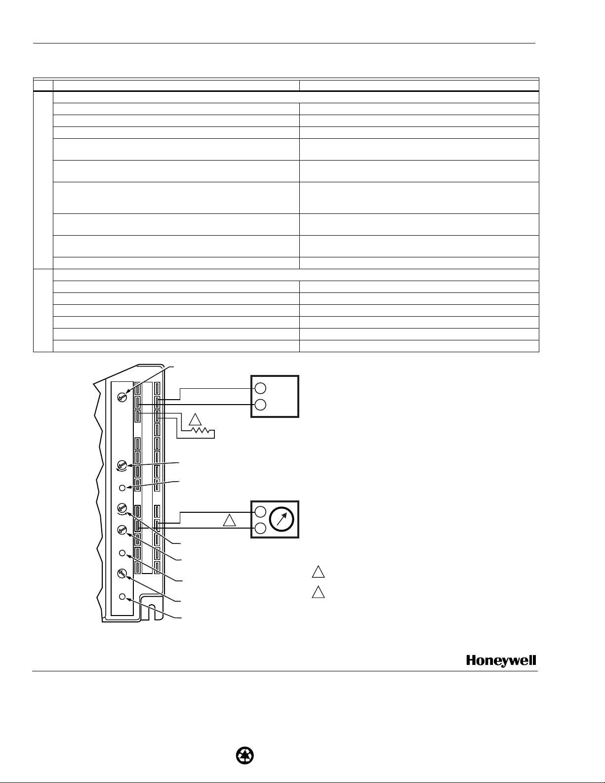
CHECKOUT AND TROUBLESHOOTING
Checkout requires a 9V battery, 620 ohm, 1.2K ohm,
5.6K ohm, and 6.8K ohm resistors. Use Table 6 and Fig. 26
for checkout.
63-2544—3 26
CAUTION
Equipment Damage Hazard.
Excessive force can damage potentiometer
controls.
Use a small screwdriver when adjusting enthalpy
changeover and minimum damper position controls.
Page 27

W6215, W7215, W7460 ECONOMIZER LOGIC MODULES
Table 6. Checkout For W6215, W7215, W7460 Economizer Connected To Honeywell Actuator.
Step Checkout Procedure Proper Response
1. CHECKOUT PREPARATION
a. Disconnect power at TR and TR1. Free Cool, Unit Control, Indoor Fan, and Exhaust Fan contacts are open.
b. Disconnect devices at P and P1, and Q and Q1. c. Jumper P to P1, and Q to Q1.
d. Turn minimum position potentiometer fully CCW.
e. Turn maximum position potentiometer fully CW.
f. Place 6.8K ohm resistor across T and T1.
g. Jumper TR to 1.
h. If connected, remove C7400 Enthalpy Sensor from terminals S
Connect 1.2K ohm 4074EJM Checkout Resistor across terminals S
and +.
O
and +.
O
i. Set both ISI and Exhaust potentiometers fully CCW.
j. Put 620 ohm resistor across S
and +.
R
k. Set enthalpy potentiometer to D.
l. Apply power (24 Vac) to terminals TR and TR1.
2. DIFFERENTIAL ENTHALPY
a. Execute step one, Checkout Preparation. b. Place 620 ohm resistor across S
c. Place 1.2K ohm resistor across S
and +. -
O
and +. Free cool LED turns on.
R
d. Remove 620 ohm resistor from SO and +. Free cool LED turns off.
3. SINGLE ENTHALPY
a. Execute step one, Checkout Preparation. b. Set enthalpy potentiometer to A (fully CCW). Free cool LED turns on.
c. Set enthalpy potentiometer to D (fully CW). Free cool LED turns off.
4. ISI AND EXHAUST
a. Execute step one, Checkout Preparation. b. Ensure terminals AQ and AQ1 are open. LED for both ISI and Exhaust should be off.
Actuator drives fully closed.
c. Connect 9V battery positive to AQ and negative to AQ1. LED for both ISI and Exhaust turn on.
Actuator drives 90 to 95 percent open.
d. Turn Exhaust potentiometer CW until Exhaust LED turns off. Exhaust LED turns off with potentiometer at approximately 90 percent.
Actuator remains in position.
e. Turn ISI potentiometer CW. ISI LED turns off with potentiometer at approximately 9V.
Actuator drives fully closed.
f. Turn ISI and Exhaust potentiometers CW until Exhaust LED turns on. 45 seconds after Exhaust LED turns on, Exhaust contacts close.
5. FREEZE PROTECTION
a. Execute step one, Checkout Preparation. b. Connect 9V battery positive to AQ and negative to AQ1. LED for both ISI and Exhaust turn on.
Actuator drives 90 to 95 percent open.
c. Remove 6.8K ohm resistor from T and T1. Exhaust LED turns off. Actuator drives fully closed.
d. Replace 6.8K ohm resistor across T and T1. Exhaust LED turns on. Actuator drives 90 to 95 percent open.
6. MINIMUM AND MAXIMUM POSITION
a. Execute step one, Checkout Preparation. b. Connect 9V battery positive to AQ and negative to AQ1. ISI LED turns on. Actuator drives 90 to 95 percent open.
c. Turn maximum position potentiometer to midpoint. Actuator drives to between 20 and 80 percent open.
d. Turn maximum position potentiometer to fully CCW. Actuator drives fully closed.
e. Turn minimum position potentiometer to midpoint. Actuator drives to between 20 and 80 percent open.
f. Turn minimum position potentiometer fully CW. Actuator drives fully open.
27 63-2544—3
Page 28
Printed in U.S.A. on recycled
paper containing at least 10%
post-consumer paper fibers.
W6215, W7215, W7460 ECONOMIZER LOGIC MODULES
R
Table 6. Checkout For W6215, W7215, W7460 Economizer Connected To Honeywell Actuator. (Continued)
Step Checkout Procedure Proper Response
7. AIR CHANGE, SHUTDOWN, AND PURGE
a. Execute step one, Checkout Preparation. b. Ensure terminals AQ and AQ1 are open. c. Turn minimum position potentiometer to midscale. Actuator drives to between 20 and 80 percent open.
d. Make sure Air Change, Purge, and Shutdown terminals are empty. Exhaust LED turns on.
Unit Control and Indoor Fan contacts close.
e. Jumper Air Change terminals. Exhaust LED turns on. Unit control contacts open.
Indoor Fan contacts close. Actuator drives fully open.
f. Jumper Shutdown terminals. Exhaust LED turns off.
Unit Control, Indoor Fan, and Exhaust Fan contacts open.
Actuator drives fully closed.
g. Remove Shutdown jumper. Exhaust LED turns on. Unit control contacts open.
Indoor Fan contacts close. Actuator drives fully open.
h. Jumper Purge terminals. Exhaust LED turns off. Unit Control, and Indoor Fan contacts open.
Exhaust Fan contacts close. Actuator drives fully closed.
i. Jumper Shutdown terminals. -
8. MIXED AIR INPUT
a. Execute step one, Checkout Preparation. b. Set enthalpy potentiometer to A. Free cool LED turns on.
c. Replace 6.8K ohm resistor (across T and T1) with 5.6K ohm resistor. Actuator drives to between 20 and 80 percent open.
d. Remove 5.6K ohm resistor and jumper T to T1. Actuator drives fully open.
e. Remove jumper from T to T1 and leave open. Actuator drives fully closed.
f. Replace 6.8K ohm resistor across T and T1. Actuator drives fully closed.
W6215A
TR Hot
24VAC
BC
A
Mininum
Position
Open
Free Cool
Maximum
Position
Closed
6
2
ISI
Set Pt
ISI
50%
0%
100%
Exhaust
Set Pt
Exhaust
TR1
Com
+
D
So
+
Sr
5
1
2
3
4
T
T1
P
P1
Q
Q1
AQ
AQ1
10
Q
SD
SD1
AC
AC1
Q
PG
PG1
Q
ENTHALPY
CHANGEOVER
SETPOINT
+
C7400
S
2
620 OHM
JUMPER
MINIMUM DAMPER POSITION SETTING
LED LIGHTS WHEN OUTDOOR AIR
IS SUITABLE FOR FREE COOLING
–
1
MAXIMUM DAMPER
POSITION SETTING
INDOOR AIR
SENSOR SETPOINT
LED LIGHTS WHEN INDOOR SENSOR
INPUT IS ABOVE SETPOINT
EXHAUST FAN SETPOINT
+
DC VOL TMETER
1
INSERT DC VOLTMETER BETWEEN AQ AND AQ1 FO
CHECKOUT AND TROUBLESHOOTING.
2
JUMPER USED FOR SINGLE ENTHALPY CONTROL.
LED LIGHTS WHEN EXHAUST IS ON
Fig. 26. Meter location for checkout and troubleshooting.
By using this Honeywell literature, you agree that Honeywell will have no liability for any damages arising out of your use or modification to, the literature. You will defend and indemnify
Honeywell, its affiliates and subsidiaries, from and against any liability, cost, or damages, including attorneys’ fees, arising out of, or resulting from, any modification to the literature by you.
M11807
Home and Building Control Home and Building Control Honeywell International Honeywell Europe S.A.Honeywell Latin American
Honeywell Honeywell Limited-Honeywell Limitée Home and Building Control 3 Avenue du Bourget Region
1985 Douglas Drive North 35 Dynamic Drive Honeywell Building 1140 Brussels 480 Sawgrass Corporate Parkway
Golden Valley, MN 55422 Scarborough, Ontario 17 Changi Business Park Central 1 Belgium Suite 200
M1V 4Z9 Singapore 486073 Sunrise FL 33325
63-2544—3 B.B. Rev. 9-01 www.honeywell.com/building/components
 Loading...