

Honeywell VU443, VU444 Installation Manual
VU53F,N,S,T; VU54F,N,S,T; VU443A; VU444A; VU843A; VU844A
FAN COIL VALVES AND ACTUATORS
How to Find Valve Pressure Drop
SI (metric) units (Fig.3)
1. Calculate desired flow through valve in m
3
second. L/s = 3.6 X m
/h.
2. Determine the kv rating of the valve.
3. Select the graph corresponding to the kv rating.
3
/h or litres/
4. Determine the pressure drop across the valve by:
3
1. Locate the flow rate (in m
/h on the left edge of the
graph).
2. Draw a line from the flow rate to the intersection of
the kv line.
3. Draw a line from the intersection to the bottom to
determine the pressure drop in kPa or Bar.
10
5
3
3
1
Flow(m/h)
0.5
0.3
0.1
kPa
Bar
INSTALLATION
kv7.0
kv6.0
kv3.4
1 3 5 30 50 3001 0 1 0 0
0.01 0.1 1.0
Pressure Drop
Fig. 3. Flow characteristics of VU53, VU54 valves, SI units.
kv3.0
kv0.8
36
21
18
10.8
7.1
3.6
2.2
1.1
0.9
0.7
0.4
Flow (L/s)
When Installing this Product…
1. Read these instructions carefully. Failure to follow them
could damage the product or cause a hazardous
condition.
2. Check the ratings given in the instructions and on the
product to make sure the product is suitable for your
application.
3. Installer must be a trained, experienced service
technician.
4. After installation is complete, check out product
operation as provided in these instructions.
CAUTION
1. Disconnect power supply before connecting
wiring to prevent electrical shock or equipment
damage.
2. On 24V systems, never jumper the valve coil
terminals even temporarily. This can burn out the
heat anticipator in the thermostat.
3. Wear safety glasses to protect eyes from
injury when removing or installing the large
spring clip that holds the actuator mounting
plate to the valve body.
Use proper snap ring pliers to remove or
install spring clip.
95C-10885
Mounting
The valve can be mounted in any position on a vertical line.
See Fig. 5. If the valve is mounted horizontally; the actuator
must be even with or above the center line of the piping.
Make sure to leave enough room above the actuator to
remove the cover or actuator for servicing.
Mount the valve directly in the tube or pipe. Make sure that
the flow through the valve is in the direction indicated by
the arrow stamped on the valve body.
HORIZONTIAL
PIPING
VERTICAL
PIPING
Fig. 5 Mounting positions.
4
M10162
VU53F,N,S,T; VU54F,N,S,T; VU443A; VU444A; VU843A; VU844A
On diverting valves, the three fittings or ports are labeled on
the bottom of the valve body casting. Port AB is the inlet port
and is open at all times. Port A is closed and port B is open
when the valve is de-energized. Refer to the equipment
manufacturer instructions to determine which port (A or B)
should be connected to the coil bypass.
Sweat Copper Models
1. Use new, properly reamed pipe, free from dents or
corrosion.
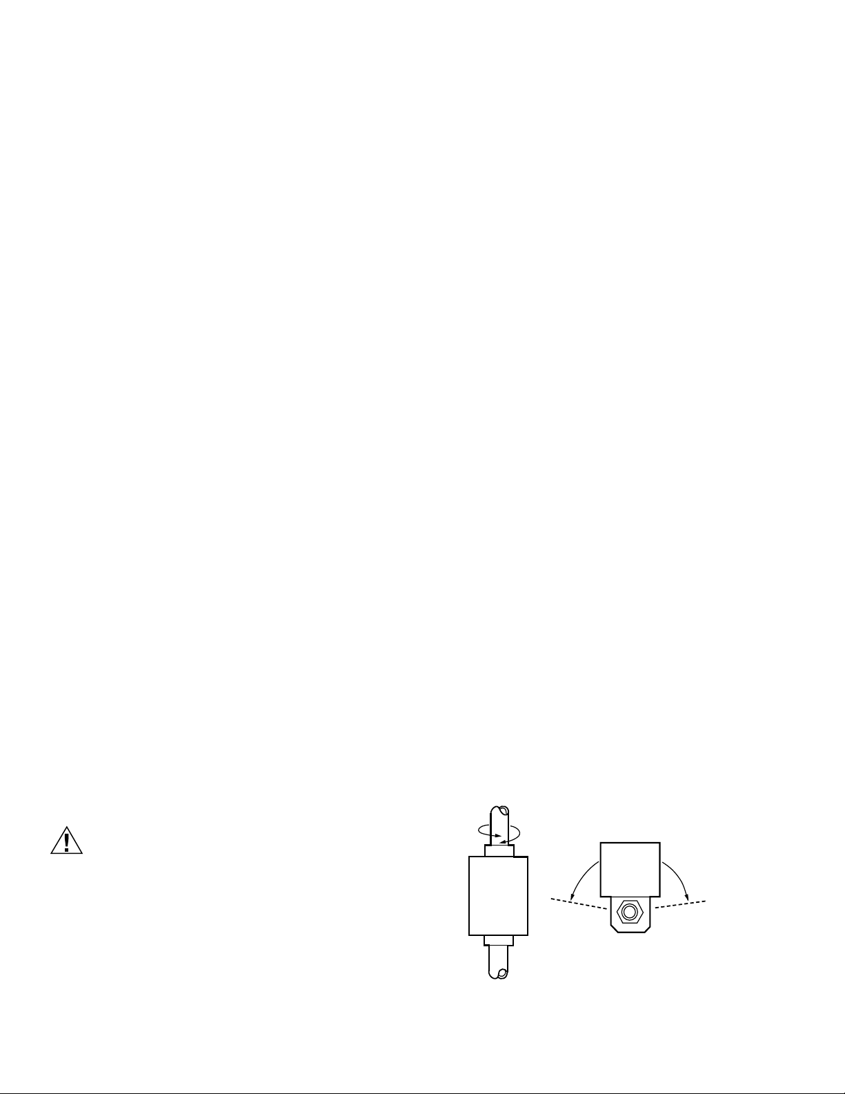
2. Place the valve on the pipe. Rotate valve stem so that
the shaft slot points at the notch in the side of the body
(90° to flow directions.) See Fig. 6. This protects the
plug inside the valve by removing it from the seat.
3. Sweat the joints, keeping the outer surface free from
solder. DO NOT use silver solder because of the high
melting temperature required.
SHAFT SLOT IN VALVE STEM
POINTING TO NOTCH ON SIDE OF
NOTCH
VALVE BODY
NOTCH
FAN COIL VALVES AND ACTUATORS
ACTUATOR
COUPLING
ENSURE SHAFT
SLOT
POINTS TOWARDS
NOTCH ON SIDE
OF BODY FOR
FITTING INTO
ENGAGING SHAFT
Fig. 6 Slot position.
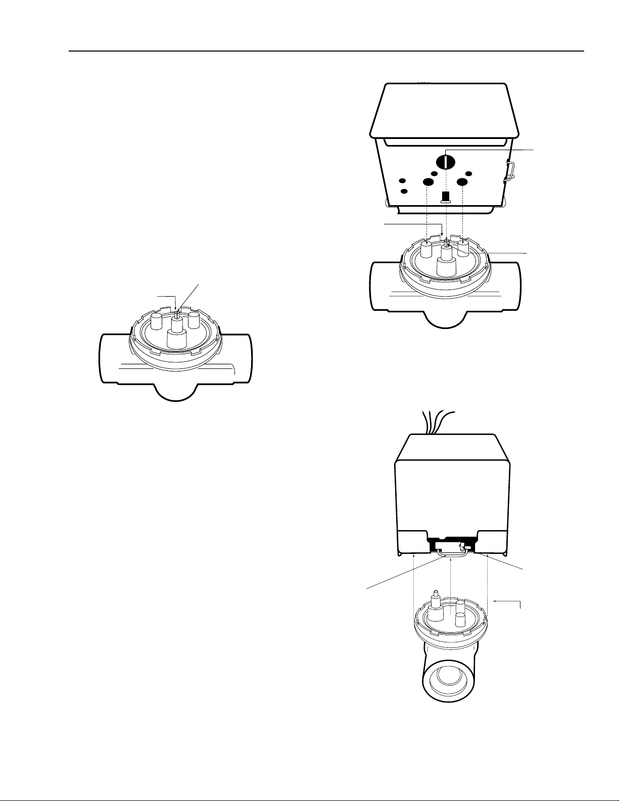
To Install & Remove Actuator
INSTALLING ACTUATOR ON VU-SERIES VALVE
BODY ASSEMBLY(See Gig. 7) :
Orient slot in shaft of VU-series valve body toward
1.
notch in side of body (i.e. 90
This lifts the ball off seat, prevents damage to the ball seat
while soldering, and makes actuator attachment easier.
2. Install valve body into pipe.
3. Wiring connections may be made either before or after
actuator installed on valve body.
Place manual operating lever on the actuator in
4.
the MAN. OPEN position.
5. Line up motor coupling to slot in shaft of body and fit the
head onto the valve body, ensuring that the shaft seats
correctly. (See Fig. 7)
6. Snap actuator onto body by pressing down.
7. Make wiring connections. Refer to wiring section for proper
instructions.
°
to water flow.) See Fig. 7
Fig. 7 Installing new actuator.
REMOVING ACTUATOR FROM THE VU-SERIES VALVE
BODY ASSEMBLY (See Fig. 8):
.
AUTO OPEN
1. PLACE MANUAL
2.
DEPRESS
3. LIFT ACTUATOR
Inspect the actuator installation and the valve body to
ensure that all connections and adjustments have been
correctly made. Adjust the thermostat or controller
connected to the valve so that the valve runs through its
cycle. Make sure the valve runs smoothly and positively
from closed to open to closed again.
Fig. 8 Removing actuator from valve
5
95C-10885
 Loading...