

Honeywell VSD-261P Operation Manual

Read this Manual carefully before installation and keep it by hand for future reference.
VISTA Series VSD TM Speed Dome
VSD-261P Operation Manual
2
CAUTION
z Persons without technical qualifications should not attempt to operate this dome device before reading this Manual
thoroughly.
z Remove any power to the dome before attempting any operations or adjustments inside the dome cover to avoid
potential damage to the mechanism.
z Inside the dome cover there are precision optical and electrical devices. Heavy pressure, shock and other sudden
adjustments or operations should be avoided. Otherwise, you may cause irreparable damage to the product.
z Please DO NOT remove or disassemble any internal parts of the video camera to avoid normal operation and possibly
void the warranty. There are no serviceable parts inside the camera.
z Please connect all the wires of the dome strictly accordingly to the specifications, It is highly recommended that the
proper lightning arrestors and surge suppressors are installed before the dome is entered into service.
z Please do not use the product under circumstances where the limits exceed the maximum specified temperature,
humidity or power Supply specifications.
z Suggest using UPS or other stable power supply system to make sure camera system can work normally.
1

1
Table of Contents
Cautions ……………………………………………1 Auto AF…………………………………………18
Package contents …………………………………1 Auto AE…………………………………………18
Chapter One – Introduction ………………………1 Vector Scan AF ………………………………18
1.1 Performance Characteristics ………………1 Vector Scan Still …………………………………18
1.2 Features and Functions ………………………1 4.5 Diagnostic Options ……………………………18
Chapter Two – Camera installation ………………2 Clear Memory …………………………………18
2.1 Important Safeguards ………………………2 Restore Def Setting ……………………………18
2.2 Package Contents ……………………………3 Color System … …………………………………19
2.3 Camera Installation …………………………4 Dome Information ………………………………19
2.4 Camera Shroud installation …………………5 4.6 Camera Options ………………………………19
2.5 Bracket installation……………………………5 Camera Name ……………………………………20
2.6 Installation of the acrylic dome cover…………7 Zoom and Focus ………………………………20
2.7 Wiring Specifications …………………………8 Camera Exposure ………………………………21
Chapter Three Basic Configuration ………………9 Mask Zone ………………………………………22
3.1 Wiring ……………………………………………9 Mask Color………………………………………22
3.2 Protocol and baud rate setting ………………10 Others… …………………………………………23
3.3 Address setting of each dome …………………11 4.7 Function Programming …………………………23
3.4 Controller setting ………………………………11 PTZ Tour ………………………………………23
Chapter Four Menu setting …………………………12 Program Vector Scan …………………………24
4.1 Operation instruction ………………………12 Annex: Short-cut Operations and Specifi-
Main Menu ……………………………………12 cation of Dome device …………………25
Number Programming Instruction ………………12 Short-cut Operation Table … ………26
4.2 Main Menu ……………………………………12 Product Specifications ………………27
4.3 Display Options ………………………………13 Lightning arresters and Surge
PreShot …………………………………………13 Suppressors ………………………………28
Setting of Sector ………………………………15
Coordinates ……………………………………17
Crosshairs ………………………………………17
Start-Up Scr Msg ………………………………17
4.4 Control Options ………………………………17
Set Pan and Tilt ………………………………17
Set Default Function ……………………………18
Speed Limit ……………………………………18
Auto Flip ………………………………………18

2
Package Contents
Please check the quantity of the package contents when open the carton.
Description Qty
Manual, Certificate each1
BNC Wire 1
Rubber Cushion 1
Lower housing of dome 1
Bag of screws 1
High Speed Dome 1
Camera Module 1
Wall bracket 1
AC24V transformer 1
Camera Shroud 1
Terminal 2
Please contact the distributors in time if the spare parts are missing.
1

1
Chapter One – Introduction
1.1 Performance Characteristics
z 0~255 individually addressed units. The dome address is defined using a dip switch with 8 positions (Binary
addressing scheme).
z Integrated multi-protocol and auto protocol differentiation. Note: The dome can auto differentiate the protocol of
the Controller only on power Up.
z Continuous Pan 360 degree rotation.
z 90 degree Tilt action plus 2 degree angle adjustment (the view angle can be 90 or 92 degrees).
z Pan speed in manual operation is variable from 0.1 Up to 300 degrees per second.
z Tilt speed in manual operation is variable from 0.1 to 120 degrees per second.
z 128 preset positions. (A preset position is defined as a user definable setting for precise coordinates).
z The maximum speed when a preset position is called can reach 400 degrees per second with positioning accuracy of±
0.1 degree.
z Input power Supply: 24VAC-2Amp (outdoor).
z User friendly on screen menu interface for ease of installation.
z Environmental protection conforming to IP66 standards (outdoor model).
z RS-485 (long distance) communications mode.
z Selectable transmission speed, (i.e. Baud rate). User definable via dip switch setting from 2400bps to 1920 bps.
1.2 Features and Functions
z Multi-language on screen menu for operation and function settings.(The camera title is user definable as well as the
ability to display or not the camera coordinates).
z On screen Crosshair function (By enabling this option, the target can be followed more effectively using the crosshairs
as a reference point).
z Three user definable PTZ tours with Up to 2 minutes record duration for each tour. (User has the ability in real-time to
monitor and record the action of a manual dome operation).
Six group of programmable vector scans (including scan speed, dwell time, preset and dwell time between tours) Auto
flip function in tilt action + 10 degree positioning.
z 24 sectors of user programmable privacy zones (sectional mask) .User can mask part of the camera sectors which
differs between different models of installed cameras.
z Eight sectors of user programmable sectional display. User can define and display the name and position of the camera,
which differs between different models of installed cameras.
z Resume automatic operation after initial self-test of the dome as well as resume automatic operation when there is no
transmission from a keyboard controller (Dwell time can be set from 1 to 999 seconds).
z Freeze frame function (Snapshot function availability Supported by camera).
z Resume operation function (Dome unit will return to the previous operation after the execution of an operation using
the on screen menu).
z Intelligent manual scan function (By executing this function in manual pan, you can adjust the manual pan behavior of
the dome).

2
z Intelligent power off real time memory (Should power fail while the dome was in operation,the dome well resume its
preprogrammed function upon power restore).
z Highly efficient 3-dimensional scan function (User can change the pan scan tour when the dome is in manual scan or
auto scan between two pan points).
z Zoom and dome speed correction function (When the zooming-in of the camera is disabled, the dome speed is reduced
to allow for precise operation control).
Chapter Two – Camera installati on
2.1 Important Safeguards
2.1.1 Read this Manual and Intelligent Camera Operation Guideline before attempting installation or operation of
dome device(This manual will be subject to revision without further notification).
2.1.2 Power Supply: AC24V.The input voltage of the dome is indicated on the bottom of the dome device or on the
input position.
2.1.3 Inside the dome cover there are precision optical and electrical devices.
Heavy pressure, strong shaking and other sudden adjustment or operations should be avoided
during the transportation. Otherwise, you may cause irreparable damage to the product.
2.1.4 Please DO NOT remove or disassemble any internal parts of the video camera to avoid
normal operation and possibly void the warranty.
2.1.5 During usage, user should abide by all electrical safety standards.
Use only the power supply specified by manufacturer. The control cable
for RS485 communications as well as the video signal cables should be
isolated from high voltage equipment and or high voltage cables.
It is highly recommended that the proper lightning arresters and surge
suppressors are installed before the dome is entered into service.
2.1.6 Indoor dome is for indoor use only and not suitable for outdoor or
high humidity ratings. Use outdoor dome for high humility location or in the rain.
2.1.7 Please do not use the product under circumstances where the limits
exceed the maximum specified temperature, humidity or power Supply specifications.
2.1.8 Avoid pointing the camera directly to the sun or other extremely bright objects for prolonged period of time.
2.1.9 Cleaning agent of abrasion should not be used to clean the dome device.
Use a piece of dry cloth to clean and dry the device.
2.1.10 Use the camera carefully to avoid striking or shaking.
2.1.11 Verify that the surface you are planning to use for attaching the dome
can adequately support the weight of the device and mounting hardware.
2.1.12 Should the lens of the camera become dirty, use special lens cleaning cloth and solution to properly clean it
3
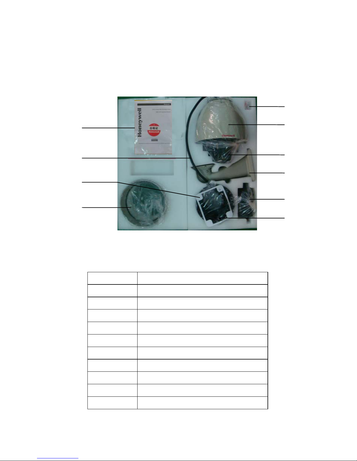
2.2 Package Contents
2.2.1 Below figures illustrate the package contents.
Figure 1. Illustrates the Upper layer of the carton (top half), Figure 2. Illustrates the lower layer of the carton (bottom
half).
Fig 1 Fig 2
Sequence No. Description
1 Manual, Certificate
2 BNC Wire
3 Rubber Cushion
4 Lower housing for the dome, Terminal
5 Bag of Screws
6 High Speed Dome
7 Camera Module
8 Wall bracket
9 AC24V transformer
10 Camera Shroud
2
3
4
5
6
7
8
9
10
1
4
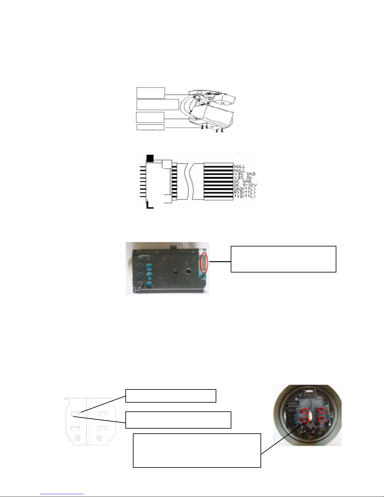
2.3 Camera Installation
2.3.1 Ribbon cable:Insert FPC socket of the cable to the relevant port of the base plate on the dome control board.
(Ribbon cable length of 65MM and110MM, user can select the ribbon cable according to the different models of camera)
Figure 4 below illustrates the writing configuration of the ribbon/cable.
FP C
Connector
FP C
Connector
FFC
Flexible Flat Cable
4-PWM2*6
Fig.3
Fig.4
Output of ribbon cable
Fig.5
2.3.2 Install the camera module: Install the camera module on the vertical axis tray of the dome as illustrated in Fig. 6 and
Fig. 7. Attention: Take care not to scratch th e l ens when instal l in g th e camera. Do make sure the camera model is
the right one for instal lat ion . Secu re the ca mera to th e c orrespo ndi ng s crew holes as ill ustrated in Fig . 6 , acco rdi ng
to the model and make of the camera, as different camera models may have different dimensions. Fo llowing the
installation of t he camera modu le verify that it does not touch an y of the dome p arts in cluding th e camera shroud
and acrylic dome by gently moving the camera module along the vertical axis.
Fig.6 Fig.7
Insert the camera ribbon to the camera
FPC Socket to secure the connection.
Sony camera model screw holes
Install the camera module on the vertical axis
tray of the dome as illustrated in Fig.7 using the
4 supplied PWM2*6 Screws.
Honeywell camera model screw holes
FPC Socket
5
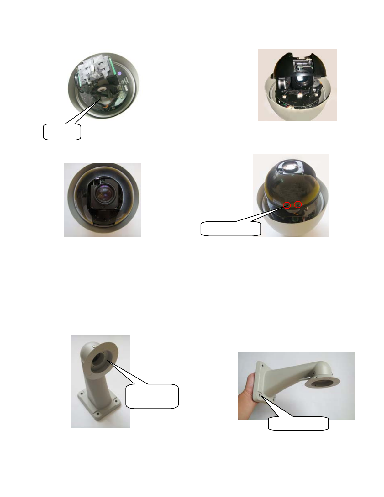
2.4 Camera Shrou d installation
Fig.8 illustrates the location of the 4 screw holes for the camera shroud (M3).
Fig.8 Fig.9
Fig.10 Fig.11
2.4.1 Position the open end of the camera shroud towards the camera lens as illustrated on Fig. 9. Align the 4 holes of the
shroud with the 4 holes on the core of the dome as illustrated in Fig. 10.
2.4.2 Utilizing the supplied (4) four M3*14 screws securely tighten the camera shroud in place, as illustrated in Fig. 11.
2.5 Bracket installation
2.5.1 Feed the BNC wiring harness through the channel inside the wall bracket as illustrated in Fig 12. Ve r i f y t h a t
the channel remains empty before feeding the wiring harness
Fig.12 Fig.13
2.5.2 Affix the wall bracket to the wall using 4 M6 Expand screws as illustrated in Fig 13.
Screw holes
Tighten the screws
Feed the BNC
Wiring from here
4-M6 expand screw
6
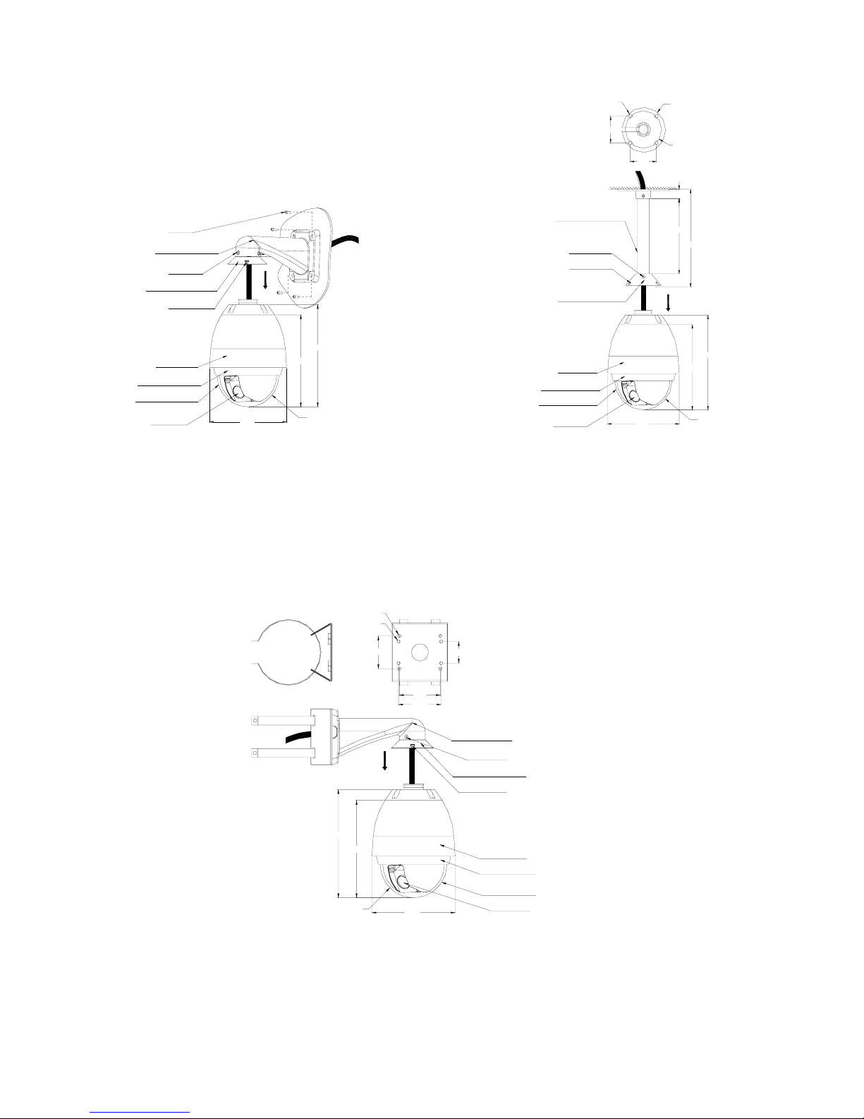
Fig. 14 illustrates installation of wall bracket Fig 15 illustrates installation of pendent bracket
2-PM5*14
4-M6
3-M5*8
OD housing
Bracket adapter
195.4
252.1
SR78.5
226.7
Wall bracket
Inner housing
Clear acrylic
Camera
4-M8
3-PM5*12
2-PM4*10
Bracket adapter
260.0
200.0
25.0
70.7
70.7
? 100.0
? 120.0
195.4
252.1
SR78.5
226.7
Pendent bracket
OD housing
Inner housing
Clear acrylic
Camera
Fig.14 Fig.15
Fig. 16 illustrates installation of pole bracket
2-PM5*14
Bracket adapter
3-M5*8
96.0
100.0
4-M8
4-M8
76.0
50.0
195.4
226.7
SR78.5
252.1
Pole bracket
Camera
Clear acrylic
Inner housing
OD housing
Fig.16
 Loading...