

Page 1
VS8510,VS8520
OBSOLETE
Millivolt Gas Valve
INSTALLATION INSTRUCTIONS
APPLICATION
The VS8510, VS8520 Millivolt Gas Valve is compact and
has a 60,000 Btuh capacity (1 in. pressure drop for
straight through configuration). Its design makes it ideal
for fireplace and space heating applications.
SPECIFICATIONS
Main Gas Connection:
Pilot Gas Connection and Flow:
Connection Size: 7/16-24 UNS.
Flow: 1700 Btuh at 4.0 in. wc pressure drop.
Thermocouple and Pilot Threads:
Ambient Temperature Range:
0°F to 175°F (-18°C to 79°¡C).
Option for 225°F (107°C).
Pressure Regulation:
Servo regulator with adjustable outlet pressure.
Natural Gas: Typically 3.5 in. wc.
LP: Typically 11 in. wc.
Regulator Adjustments:
Natural Gas: 3 in. to 5 in. field adjustable.
LP: 8 in. to 12 in. field adjustable.
Vol ta ge:
VS8510: 750 mV operator.
VS8520: 750 mV operator, 30 mV thermocouple.
Approvals:
International Approval Services (IAS) Certificate:
C2030022.
European Community (CE) Certificate: Applied for.
Valve: 3/8 in. NPT thread.
Metric and UNS.
INSTALLATION
When Installing this Product...
Read these instructions carefully. Failure to follow
1.
them could damage the product or cause a
hazardous condition.
Check the ratings given in the instructions and on
2.
the product to make sure the product is suitable for
your application.
Installer must be a trained, experienced service
3.
technician.
After installation is complete, check out product
4.
operation as provided in these instructions.
WARNING
Oxygen depletion hazard.
Can cause injury or death due to
asphyxiation.
Use only vented gas valve models on vented
1.
appliances.
Use only unvented gas valve models on
2.
unvented appliances.
WARNING
Fire or explosion hazard.
Can cause property damage, severe injury or
death.
Follow these warnings exactly:
Disconnect power supply before wiring to
1.
prevent electrical shock or equipment damage.
To avoid dangerous accumulation of fuel gas,
2.
turn off gas supply at the appliance service
valve before starting installation, and perform a
Gas Leak Test after the installation is
complete.
Always install the sediment trap in the gas
3.
supply line to prevent contamination of the gas
control.
Do not force the gas control knob. Use only
4.
your hand to turn the gas control knob. Never
use any tools. If the gas control knob does not
operate by hand, the gas control should be
replaced by a qualified service technician.
Force or attempted repair can result in fire or
explosion.
® U.S. Registered Trademark
Copyright © 2000 Honeywell Inc. •All Rights Reserved
69- 1024- 5
Page 2
VS5810, VS5820 MILLIVOLT GAS VALVE
OBSOLETE
CAUTION
Equipment damage.
Can burn out heat anticipator in thermostat.
Never apply a jumper across or short the valve
coil terminals.
IMPORTANT
These gas controls are shipped with protective
seals over the inlet and outlet tappings. Do not
remove the seals until ready to connect the
piping.
Follow the appliance manufacturer instructions, if
available; otherwise, use these instructions.
Converting Between Natural and LP Gas
WARNING
Fire or explosion hazard.
Can cause property damage, severe injury or
death.
Do not use a gas control set for natural gas on
1.
an LP gas system or a gas control set for LP
gas on a natural gas system.
When making a conversion, the main pilot
2.
burner orifices must be changed to meet the
appliance manufacturer specifications.
When making a conversion, change main pilot burner
orifices to meet the appliance manufacturer
specifications. Refer to the appliance manufacturer
instructions for orifice specifications and changeover
procedure. Gas controls are factory-set for natural (and
manufactured) or LP gas. Do not attempt to use a control
set for natural (manufactured) gas on LP gas, or a control
set for LP on natural (manufactured) gas.
VS8510A and VS8520A gas controls with a standard
regulator can be converted from one gas to the other with
a conversion kit (ordered separately). Order part no.
395991 to convert from natural (manufactured) to LP
gas. Order part no. 395992 to convert from LP to natural
(manufactured) gas.
VS8510E and VS8520E gas controls with a Convertible
High/Low regulator can be converted from one gas to the
other with a conversion kit (ordered separately). Order
part no. 396087-1 to convert from LP to natural
(manufactured) gas. Order part no. 396087-2 to convert
from natural (manufactured) to LP gas.
High/Low regulator models VS8510D and VS8520D
cannot be converted.
VS8510R and VS8520R
Convertible Pressure Regulators
Gas valves with suffix letter R are convertible pressure
regulator models. They can be converted from natural
gas to LP or from LP to natural gas without a converter
kit.
Before converting the gas valve from one gas to another,
check the gas valve label and the appliance
manufacturer rating plate to make sure the pressure
regulator setting (factory set) meets the appliance
manifold requirements after conversion.
NOTE: Convertible pressure regulator models (suffix
R) do not have field-adjustable regulators. The
natural gas and LP settings are factory-manufactured.
IMPORTANT
Follow these instructions carefully.
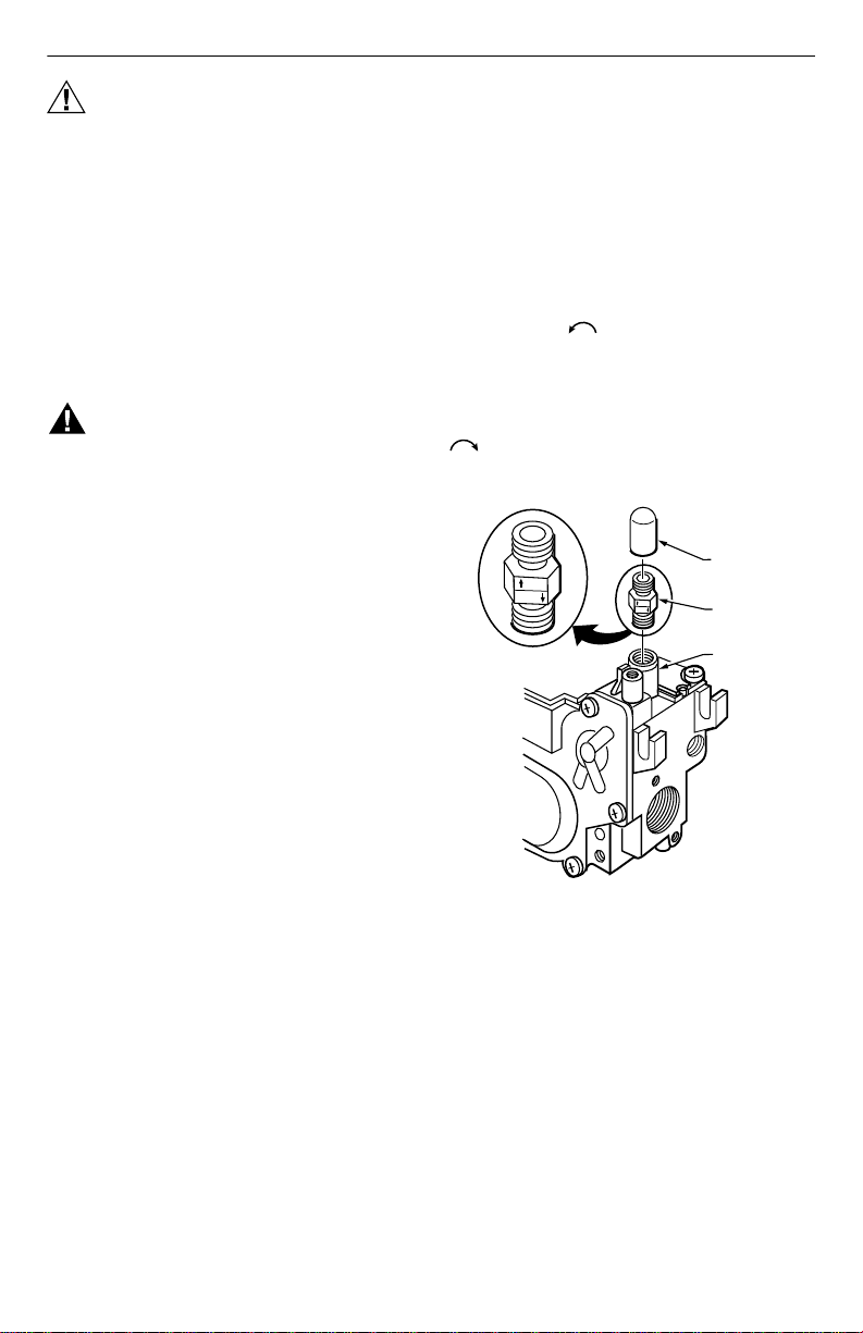
CONVERTING THE GAS VALVE
If the factory pressure regulator setting meets the
appliance manifold requirement, convert the gas valve as
follows (see Fig. 1):
Remove the black thread protective cap.
1.
Remove the conversion flip cap by turning it
counterclockwise .
Invert the conversion flip cap so the bottom of the
2.
letters and associated arrow for the gas type
appropriate for the appliance application are face
down toward the valve. NAT is for natural gas and
LP is for liquid petroleum gas.
Tighten the conversion flip cap by turning it clockwise
, using 10 in. lbs of force.
Replace the black thread protective cap.
PROTECTIVE
LP
NAT
Fig. 1. Converting the gas valve (shown
assembled for natural gas).
LP
NAT
CAP
CONVERSION
FLIP CAP
PRESSURE
REGULATOR
HOUSING
M16521
Location
Locate the combination gas control where it cannot be
affected by steam cleaning, high humidity, dripping water,
corrosive chemicals, dust or grease accumulation or
excessive heat. To assure proper operation, follow these
guidelines:
• Locate gas control in a well-ventilated area.
• Mount gas control high enough to avoid exposure to
flooding or splashing water.
• Assure the ambient temperature does not exceed the
ambient temperature ratings for each component.
• Cover gas control if appliance is cleaned with water,
steam, or chemicals or to avoid dust and grease
accumulation.
• Avoid locating gas control where exposure to
corrosive chemical fumes or dripping water is likely.
69-1024—5 2
Page 3
VS5810, VS5820 MILLIVOLT GAS VALVE
OBSOLETE
Install Piping to Gas Control
All piping must comply with local codes and ordinances
or with the National Fuel Gas code (ANSI Z223.1 NFPA
No. 54), whichever applies. Tubing installation must
comply with approved standards and practices.
Use new, properly reamed pipe free from chips.
1.
When tubing is used, assure the ends are square,
deburred and clean. All tubing bends must be
smooth and without deformation.
Run pipe or tubing to the control. If tubing is used,
2.
obtain a tube-to-pipe coupling to connect the
tubing to the control.
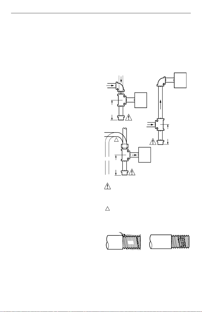
Install sediment trap in the supply line to the gas
3.
control. See Fig. 1.
Install Control
Mount control 0 to 90 degrees, in any direction,
1.
from the upright position of the gas control knob,
including vertically.
Mount the control so gas flow is in the direction of
2.
the arrow on the side of the control.
Thread pipe 9/16 in. into the control. Do not insert
3.
deeper than 3/8 in. Valve distortion or malfunction
can result if the pipe is inserted too deeply.
Apply a moderate amount of good quality pipe
4.
compound (do not use Teflon tape) to pipe only,
leaving two end threads bare. On LP installations,
use compound resistant to LP gas. See Fig. 2.
Remove seals over control inlet and outlet, if
5.
necessary.
Connect pipe to control inlet and outlet. Use
6.
wrench on either side of the pipe outlet. Refer to
Fig. 3 through 5.
Wiring
Follow the wiring instructions furnished by the appliance
manufacturer, if available, or use the general instructions
provided below. Where these instructions differ from the
appliance manufacturer, follow the appliance
manufacturer instructions. For typical wiring diagrams,
see Fig. 6 and 7.
All wiring must comply with applicable electrical codes
and ordinances.
Disconnect power supply before making wiring
connections to prevent electrical shock or equipment
damage.
Check the power supply rating on the gas control
1.
and make sure it matches the available supply.
Install the transformer, thermostat, and other
controls, as required.
This valve can only be used in a self-generating
2.
system.
Adjust the thermostat heat anticipator to the 0.1A
3.
at 750 mV rating stamped on the valve operator.
OPERATION
The Millivolt Gas Valve System has two different
configurations. The first configuration includes a gas
valve, quick drop-out thermocouple, thermopile, millivolt
thermostat and a pilot burner. In this configuration, the
thermopile drives the operator and the quick dropout
thermocouple operates the power unit. See Fig. 7. The
second configuration includes a gas valve, thermopile,
millivolt thermostat, and a pilot burner. The thermopile
drives the operator and the power unit. See Fig. 8.
DROP
HORIZONTAL
3 INCHES
(76 MM)
MINIMUM
HORIZONTAL
ISER
3 INCHES
(76 MM)
MINIMUM
CAUTION
GAS LEAKAGE HAZARD.
FAILURE TO FOLLOW PRECAUTIONS CAN
RESULT IN A GAS-FILLED WORK AREA.
SHUT OFF THE MAIN GAS SUPPLY BEFORE REMOVING END CAP.
TEST FOR GAS LEAKAGE WHEN INSTALLATION IS COMPLETE.
1
ALL BENDS IN METALLIC TUBING SHOULD BE SMOOTH.
TWO IMPERFECT
THREADS
THREAD PIPE ACCORDING TO
INSTALLATION PROCEDURE FOR
INSERTION INTO GAS CONTROL.
PIPED
GAS
SUPPLY
GAS
CONTROL
DROP
TUBING
1
GAS
SUPPLY
GAS
CONTROL
Fig. 2. Sediment trap installation.
GAS CONTROL
PIPE
APPLY A MODERATE AMOUNT OF
PIPE COMPOUND TO PIPE ONLY
(LEAVE TWO END THREADS BARE).
RISER
PIPED
GAS
SUPPLY
3 INCHES
(76 MM)
MINIMUM
GAS
CONTROL
M4603A
M6913
Fig. 3. Use moderate amount of pipe compound.
3 69-1024—5
Page 4

VS5810, VS5820 MILLIVOLT GAS VALVE
OBSOLETE
WIRING
TERMINALS
HI
O
L
OUTLET
PRESSURE TAP
Fig. 4. Top view of gas control with HI/LO regulator.
INLET
PRESSURE TAP
HI/LO REGULATOR
PILOT
ADJUSTMENT SCREW
PILOT
ON
GAS
CONTROL KNOB
APPLY WRENCH
FROM BOTTOM OF
GAS CONTROL TO
SHADED AREA
OFF
M6914
WIRING
TERMINALS
OUTLET
PRESSURE
TAP
INLET
PRESSURE TAP
PRESSURE REGULATOR
ADJUSTMENT (UNDER
CAP SCREW)
Fig. 5. Top view of gas control with
standard regulator.
ON
PILOT
OFF
GAS
CONTROL
KNOB
PILOT
ADJUSTMENT
SCREW
M6915
M6916
Fig. 6. Proper use of wrench on gas control.
Pilot Gas and Lighting Procedure
Turn the knob counterclockwise to PILOT
1.
position, push the knob down, and hold in position.
The pilot valve opens and allows gas to flow to the
pilot burner.
Light the pilot burner while holding the knob down
2.
until a strong flame is present (approximately 60
seconds).
Release the knob. The shaft will move upward and
3.
engage the safety valve lever that opens the safety
valve.
Turn the knob counterclockwise to the ON
4.
position. On a call-for-heat, the main valve opens
and the main burner ignites.
Shut off Procedure
To shut off the system, turn the knob
1.
clockwise to the OFF position. This action
closes the main gas and safety valves. However,
69-1024—5 4
the power unit must drop out before the lighting
sequence can begin again. The VS8510 drops out
within three minutes. The VS8520 drops out within
30 seconds.
To relight the pilot light, follow the steps in the Pilot
2.
Gas and Lighting Procedure section.
HI/LO Regulator
As you turn the HI/LO knob, the gas pressure changes.
Turn the knob clockwise towards the HI set-
1.
ting to increase gas pressure.
Turn the knob counterclockwise towards the LO
setting to decrease gas pressure.
Minimum and maximum regulator settings vary for each
individual gas valve. See gas valve label for actual
minimum and maximum ranges. Table 1 lists possible
minimums and maximums for gas valves.
Page 5

VS5810, VS5820 MILLIVOLT GAS VALVE
OBSOLETE
MILLIVOLT
THERMOSTAT
HIGH LIMIT
CONTROL
HI
O
L
HI/LO
REGULATOR
Fig. 7. Millivolt system wiring diagram with
MILLIVOLT
THERMOSTAT
HIGH LIMIT
CONTROL
TARGET
PILOT
ON
GAS
CONTROL
KNOB
quick drop-out thermocouple.
Q313
THERMOPILE
QUICK DROP-OUT
THERMOCOUPLE
ELECTRODE
VS8520 HI/LO
MILLIVOLT
GAS VALVE
OFF
PILOT
ADJUSTMENT
SCREW
Q313
THERMOPILE
Table 1. HI/LO and Standard Regulator Specification
Type of
Gas
Natural 1.2 in. minimu m to
LP 3.7 in. minimum to
Pressures in in. wc (kPa).
HI/LO Regulator
Setting Ranges
3.5 in. maximum.
11.0 in. maximum.
3.0 minimum to 5.0
maximum.
8.0 in. minimum to 12.0
in. maximum.
Standard Regulator
Standard Pressure Regulator
Check the manifold pressure listed on the appli-
1.
ance nameplate. Gas control outlet pressure
should match the nameplate.
With the main burner operating, check the gas
2.
control flow rate using the meter clocking method
or measure the pressure by attaching a plastic
tube with a 1/4 in. shell I.D. to the manometer and
connecting the manometer to the outlet pressure
tap on the gas control. See Fig. 5.
If necessary, adjust the pressure regulator to
3.
match the appliance rating. See Table 1 for
factory-set nominal outlet pressure and adjustment
range.
a. Remove pressure regulator adjustment cap
M6917A
screw.
b. Using a screwdriver, turn inner adjustment
screw clockwise to increase or
counterclockwise to decrease gas
pressure to burner.
c. Always replace cap screw and tighten firmly to
prevent gas leakage.
If desired outlet pressure or flow rate cannot be
4.
achieved by adjusting the gas control, check gas
control inlet pressure using a manometer at the
gas control inlet pressure tap. If inlet pressure is in
the normal range (see Table 1), replace gas
control. Otherwise, take the necessary steps to
provide proper gas pressure on the control.
CHECKOUT
Setting Ranges
VS8510 HI/LO
MILLIVOLT
GAS VALVE
HI
O
L
HI/LO
REGULATOR
Fig. 8. Millivolt system wiring diagram without
quick drop-out thermocouple.
PILOT
ON
GAS
CONTROL
KNOB
OFF
PILOT
ADJUSTMENT
SCREW
M6918
WARNING
Fire or explosion hazard.
Can cause property damage, severe injury or
death.
1. Do not force the gas control knob on the
appliance. Use only your hand to turn the gas
control knob. Never use any tools.
2. If the knob does not operate by hand, the
control should be replaced by a qualified
service technician.
Gas Control Knob Settings
Gas control knob settings are as follows:
• OFF: Prevents main gas flow through the control.
• ON: Permits main burner and pilot gas flow. Gas
control and thermostat control main burner gas flow.
• PILOT: Opens pilot valve and allows gas flow to pilot
burner.
• HI/LO: Manually adjusts outlet pressure.
NOTE: Controls are shipped with the gas control knob
in the ON position.
5 69-1024—5
Page 6

VS5810, VS5820 MILLIVOLT GAS VALVE
OBSOLETE
Perform Gas Leak Test
WARNING
Fire or explosion hazard.
Can cause property damage, severe injury or
death.
1. Stand away from the main burner while
lighting. Hidden gas leaks can cause
flashbacks in the appliance vestibule.
2. Check for gas leaks with rich soap and water
solution any time work is done on a gas
system.
Gas Leak Test
Paint the pipe connections upstream of the gas
1.
control with rich soap and water solution. Bubbles
indicate a gas leak.
If a leak is detected, tighten the pipe connections.
2.
Light the main burner.
3.
With the main burner in operation, paint the pipe
4.
joints (including adapters) and control inlet and
outlet with a rich soap and water solution.
If another leak is detected, tighten the adapter
5.
screws, joints, and pipe connections.
Replace part if leak cannot be stopped.
6.
Turn on System
Rotate the gas control knob counterclockwise to
ON.
Turn on Main Burner
Follow the instructions provided by the appliance
manufacturer or turn up the thermostat to call for heat.
Check and Adjust Gas Input and Burner Ignition
CAUTION
Equipment Damage Hazard.
Improper adjustment of gas input and burner
can cause carboning and/or unnecessary
shutdown of the system.
1. Do not exceed the input rating stamped on the
appliance nameplate, or manufacturer
recommended burner orifice pressure for size
orifice(s) used. Be sure primary air supply to
the main burner is properly adjusted for
complete combustion. Follow the instructions
of the appliance manufacturer.
2. IF CHECKING GAS INPUT BY CLOCKING
GAS METER: Be sure there is no gas flow
through the meter other than to the appliance
being checked. Other appliances must remain
off with the pilots extinguished (or the
consumption must be deducted from the meter
reading). Convert the flow rate to Btuh as
described in the Gas Controls Handbook, form
70-2602, and compare to the Btuh input rating
on the appliance nameplate.
3. IF CHECKING GAS INPUT WITH MANOMETER: Both the inlet and outlet pressure
taps have a captive screw. To measure the
pressure of the tap, loosen, but do not remove
the captive screw, attach a plastic tube with a
1/4 in. shell I.D. and connect the manometer.
After checking the pressure, turn the gas
control knob to the OFF position. Before
opening the outlet press ure tap, be sure the
gas control is in the OFF position. Before
opening the inlet pressure tap, shut off the gas
supply at the manual valve in the gas piping to
the appliance or, for LP, at the tank. Repeat the
Gas Leak Test at the pressure tap with the
main burner operating.
Check Safety Shutdown Performance
WARNING
Fire or explosion hazard.
Can cause property damage, severe injury or
death.
Perform the safety shutdown test any time work
is done on a gas system.
Place gas control knob in PILOT position. Main
1.
burner should go off and pilot should remain lit.
Extinguish pilot flame. The VS8510 pilot gas flow
2.
should stop within three minutes; the VS8520 pilot
gas flow stops within thirty seconds. Safety shutoff
of pilot gas proves complete shutdown because
safety shutoff valve prohibits main burner and pilot
gas flow.
Relight pilot burner and operate the system
3.
through one complete cycle to ensure all controls
operate properly.
MAINTENANCE
WARNING
Fire or explosion hazard.
Can cause property damage, severe injury or
death.
Do not attempt to take apart the gas control or to
clean it. Improper assembly and cleaning can
cause unreliable operation.
Regular preventive maintenance is important in
applications that place a heavy load on system controls
such as those used in the commercial cooking and
agricultural and industrial industries because:
• In many such applications, particularly commercial
cooking, the equipment operates 100,000 to 200,000
cycles per year. Such heavy cycling can wear out the
gas control in one to two years.
• Exposure to water, dirt, chemicals and heat can
damage the gas control and shut down the control
system.
The maintenance program should include regular
checkout of the system as outlined in the Checkout
section, and checkout of the control system as described
in the appliance manufacturer literature.
69-1024—5 6
Page 7

Maintenance frequency must be determined individually
OBSOLETE
for each application. Some considerations are:
• Cycling frequency. Appliances that may cycle 20,000
times annually should be checked monthly.
• Intermittent use. Appliances that are used seasonally
should be checked before shutdown and again before
the next use.
• Consequence of unexpected shutdown. Where the
cost of an unexpected shutdown would be high, the
system should be checked more often.
• Dusty, wet, or corrosive environment. Because these
environments can cause the gas control to deteriorate
more rapidly, the system should be checked more
often.
Any control should be replaced if it does not perform
properly on checkout or service. In addition, replace any
module if it is wet or looks like it has ever been wet.
SERVICE
WARNING
Fire or explosion hazard.
Can cause property damage, severe injury or
death.
Do not disassemble the gas control; it contains
no replaceable components. Attempted
disassembly or repair can damage the control.
CAUTION
Equipment damage.
Can burn out heat anticipator in thermostat.
Do not apply a jumper across (or short) the valve
coil terminals even temporarily.
If Main Burner does not Come on with Call for Heat
Confirm that the gas control knob is in the ON posi-
1.
tion.
Adjust the thermostat several degrees above the
2.
room temperature.
Use a dc voltmeter to measure the voltage across
3.
the THTP and TP terminals.
If no voltage is present, check the control circuit for
4.
proper operation.
If proper control system voltage is present, replace
5.
the gas control.
VS5810, VS5820 MILLIVOLT GAS VALVE
WARNING
Fire or explosion hazard.
Can cause property damage, severe injury or
death.
Exactly follow the warnings and the lighting
instructions.
1. Before lighting, smell around the appliance
area for gas. If the appliance uses LP (bottled)
gas, be sure to smell next to the floor because
LP gas is heavier than air. If you smell gas,
immediately shut off the manual valve in the
gas piping to the appliance or, on LP, at the
tank. Do not try to light any appliance. Do not
touch any electrical switch or use the phone.
Leave the building and call your gas supplier. If
your gas supplier cannot be reached, call the
fire department.
2. Do not force the gas control knob on the
appliance. Use only your hand to turn the gas
control knob. Never use any tools. If the knob
does not operate by hand, have a qualified
service technician replace the control. Force or
attempted repair can result in fire or explosion.
3. The gas control must be replaced if it has been
flooded with water. Call a qualified service
technician.
4. The gas control is a safety device. It must be
replaced in case of any physical damage such
as bent terminals, missing or broken parts,
stripped threads, or evidence of exposure to
heat.
IMPORTANT
Follow the operating instructions provided by
the manufacturer of your heating appliance.
TROUBLESHOOTING
IMPORTANT
Troubleshooting procedures should only be performed by an experienced, qualified service
technician.
Use Fig. 9 and Table 2 or 3 to assist in troubleshooting
the VS8510 or VS8520.
TH
TH
TH
TP TPTH
M17511
Fig. 9. Test points for troubleshooting the
VS8510/VS8520 Millivolt Gas Valves.
7 69-1024—5
TP
TP
Page 8

VS5810, VS5820 MILLIVOLT GAS VALVE
OBSOLETE
Table 2. VS8510 Troubleshooting Tests.
Tes t
Letter Test Connect Meter to Set Thermostat to Meter Reading
A Coil Resistance TP and TH Open 3.6 ohms maximum.
B Thermopile TP and TPTH Open 460 mV minimum.
C Operator Pull-In TH and TP Open 155 mV minimum.
D Resistance System — Closed 1.7 ohms maximum.
A—Have thermostat contacts open and pilotstat knob turned to OFF. Coil resistance should be maximum of 3.6 ohms.
If not, replace the valve.
B—Have thermostat contacts open and pilot burning with pilotstat knob turned to PILOT. There should be a minimum of
460 mV. If not, replace thermopile.
C—Have thermostat contacts open and pilot burning with pilotstat knob in the PILOT position. Close
contacts. The thermopile should provide 155 mV. If not, replace the thermopile. If output is 155 mV or greater, the
valve operator will make an audible sound or click when it pulls in. If the valve does not make a sound, replace the
valve.
D—The system resistance from the remote switch or thermostat and leadwires should not exceed 1.7 ohms. If it does,
reduce the resistance.
Tes t
Letter Test Connect Meter to
A Coil Resistance TP and TH Open 3.6 ohms maximum.
B Thermopile TP and TPTH Open 460 mV minimum.
C Thermocouple Tip Open 18 mV minimum.
D Operator Pull-in TH and TP Open 155 mV minimum.
E Resistance system — Closed 1.7 ohms maximum.
A—Have thermostat contacts open and pilotstat knob turned to OFF. Coil resistance should be maximum of 3.6 ohms.
If not, replace the valve.
B—Have thermostat contacts open and pilot lit with pilotstat knob turned to PILOT. There should be a minimum of 460
mV. If not, replace thermopile.
C—Have thermostat contacts open and pilot burning with the pilotstat knob turned to PILOT. The voltage should be 18
mV for a new thermocouple. You must press pilotstat knob to maintain the gas flow. If the output does not meet the
minimum voltage, replace the thermocouple. The power unit will hold in down to 3 mV. If the output of the thermocouple is below 3 mV, replace the thermocouple.
D—Have thermostat contacts open and pilot burning with pilotstat knob in the PILOT position. Close
contacts. The thermopile should provide 155 mV. If not, replace the thermopile. If output is 155 mV or greater, the
valve operator will make an audible sound or click when it pulls in. If the valve does not make a sound, replace the
valve.
E—The system resistance from the remote switch or thermostat and leadwires should not exceed 1.7 ohms. If it does,
reduce the resistance.
Table 3. VS8520 Troubleshooting Tests.
Set Thermostat
to Meter should read
the thermostat
the thermostat
Home and Building Control Home and Building Control
Honeywell Inc. Honeywell Limited-Honeywell Limitée
Honeywell Plaza 155 Gordon Baker Road
P.O. Box 524 North York, Ontario
Minneapolis, MN 55408-0524 M2H 3N7
69-1024—5 G.R. Rev. 6-00 www.honeywell.com
Printed in U.S.A. on recycled
paper containing at least 10%
post-consumer paper fibers.
 Loading...