

Honeywell VS8420C Installation Instructions Manual
APPLICATION
The VS8420 Millivolt Gas Valve is compact and has a
low capacity. The design makes it ideal for central heating, fireplace, and space heating applications.
The VS8420 Millivolt Gas Valve is approved in accordance with existing European standards.
SPECIFICATIONS
VS8420C,M
Millivolt Gas Valve
INSTALLATION INSTRUCTIONS
VS8420: 750 mV operator, 30 mV thermocou-
Vol ta ge:
ple.
Approvals:
0063AU1270.
Other Features:
Pressure Tap: 9 mm outside diameter at inlet and outlet
Screen: Fine mesh inlet screen.
Interrupter (ECO) Connection: 6.3 mm tab connectors.
Piezo Sparker: Optional piezo sparker.
European Community (CE) Certificate: CE-
sides in accordance with EN 126.
Main Gas Connection:
Valve:3/8" ISO 7/1 internal thread for 12 mm outside
diameter tube.
Inlet connection at inlet side or at bottom.
Outlet connection at outlet side or at bottom.
Pilot Gas Connection and Flow:
Connection Size: M10 x 1 for 4 or 6 mm outside diame-
ter tube. At inlet side or at bottom.
Flow: Adjustable from 0.014 m3/h air at 35 mbar inlet
pressure to 0.105 m3/h at 7.5 mbar.
Thermocouple and Pilot Threads:
Metric and UNS.
Thermocouple connection: M10 x 1 at bottom. Optional at
the outlet side with use of a thermocouple re-route.
Ambient Temperature Range:
175°F).
Maximum Inlet Pressure:
Pressure Regulation (Standard Regulator):
Servo regulator with adjustable outlet pressure; in
accordance with EN 88, class C.
Natural Gas: 9 mbar, typical.
LP: 27 mbar, typical.
Regulator Adjustments (Standard Regulator):
Natural Gas: 7.5 mbar to 12.5 mbar field adjustable.
LP: 20 mbar to 30 mbar field adjustable.
In appliances where no regulation is required, the pressure regulator must be blocked by turning the pressure
regulator adjustment screw fully down. The regulator
will then be set at 30 mbar.
0°C to 80°C (32°F to
60 mbar (24 in. wc)
INSTALLATION
When Installing this Product...
Read these instructions carefully. Failure to follow
1.
them could damage the product or cause a hazardous condition.
Check the ratings given in the instructions and on
2.
the product to make sure the product is suitable
for your application.
Installer must be a trained, experienced service
3.
technician.
After installation is complete, check out product
4.
operation as provided in these instructions.
WARNING
Oxygen Depletion Hazard.
Can cause injury or death due to asphyxiation.
Use only vented gas valve models on vented
appliances. Use only unvented gas valve models on unvented appliances.
® U.S. Registered Trademark
Copyright © 1999 Honeywell Inc. • All Rights Reserved
69- 1304
VS8420C,M MILLIVOLT GAS VALVE
Ñ
Ñ
WARNING
Fire or Explosion Hazard.
Can cause property damage, severe injury or
death.
Follow these instructions exactly:
Turn off gas supply at the appliance service
1.
valve before starting installation, and perform
a Gas Leak Test after the installation is complete.
Always install the sediment trap in the gas
2.
supply line to prevent contamination of the
gas valve.
Do not force the gas valve control knob. Use
3.
only your hand to turn the control knob. If the
knob does not operate by hand, the valve
should be replaced by a qualified service
technician.
WARNING
Electrical Shock or Equipment Damage Hazard.
Can cause equipment damage, serious
injury or death.
Disconnect all power supplies before installation.
CAUTION
Equipment Damage.
Can burn out heat anticipator in thermostat.
Never apply a jumper across or short the valve
coil terminals.
IMPORTANT
These gas valves are shipped with protective
seals over the inlet and outlet tappings. Do not
remove the seals until ready to connect the
piping.
Follow the appliance manufacturer instructions, if available; otherwise, use these instructions.
Converting Between Natural and LP Gas
WARNING
Fire or Explosion Hazard.
Can cause property damage, severe injury or
death.
Do not use a gas valve set for natural gas on an
LP gas system or a gas valve set for LP gas on
a natural gas system. When making a conversion, change the main pilot burner orifices to
meet the appliance manufacturer specifications.
VS8420M gas controls with Convertible High/Low regulators can be converted from one gas to the other with a
conversion kit (ordered separately). Order part number
396087-1 to convert from LP to natural gas. order part
number 396087-2 to convert from natural gas to LP.
High/low regulator model VS8420C cannot be
converted.
Location
Locate the combination gas valve where it cannot be
affected by steam cleaning, high humidity, dripping
water, corrosive chemicals, dust or grease accumulation or excessive heat. To assure proper operation,
follow these guidelines:
• Locate gas valve in a well-ventilated area.
• Mount gas valve high enough to avoid exposure to
flooding or splashing water.
• Assure the ambient temperature does not exceed
the ambient temperature ratings for each
component.
• Cover gas valve if appliance is cleaned with water,
steam, or chemicals or to avoid dust and grease
accumulation.
• Avoid locating gas valve where it can be exposed to
corrosive chemical fumes or dripping water.
Install Piping to Gas Valve
Tubing installation must comply with approved standards and practices.
Use new, properly reamed pipe free from chips.
1.
When tubing is used, assure the ends are square,
deburred and clean. All tubing bends must be
smooth and without deformation.
Run pipe or tubing to the valve. If tubing is used,
2.
obtain a tube-to-pipe coupling to connect the tubing to the valve.
Install sediment trap in the supply line to the gas
3.
valve. See Fig. 1.
Install Valve (Using Pipe)
Mount valve 0 to 90 degrees, in any direction
1.
cluding vertically
gas control knob.
Mount the valve so gas flow is in the direction of
2.
the arrow on the side of the valve.
Thread pipe 15 mm. Do not insert deeper than10
3.
mm. Valve distortion or malfunction can result if
the pipe is inserted too deeply.
Apply a moderate amount of good quality pipe
4.
compound (do not use Teflon tape) to pipe only,
leaving two end threads bare. On LP installations,
use compound resistant to LP gas. See Fig. 2.
Remove seals over valve inlet and outlet, if nece-
5.
sary.
Connect pipe to valve inlet and outlet. Use
6.
wrench on either side of the pipe outlet. Refer to
Fig. 3 through 5.
from the upright position of the
in-
69-1304 2
VS8420C,M MILLIVOLT GAS VALVE
TAP
DROP
3 IN.
PIPED
GAS
SUPPLY
GAS
CONTROL
2
DROP
TUBING
1
GAS
SUPPLY
2
GAS
CONTROL
RISER
PIPED
GAS
SUPPLY
3 IN.
(76 MM)
MINIMUM
2
HORIZONTAL
3 IN.
(76 MM)
MINIMUM
HORIZONTAL
RISER
(76 MM)
MINIMUM
ALL BENDS IN METALLIC TUBING SHOULD BE SMOOTH.
1
CAUTION: SHUT OFF THE MAIN GAS SUPPLY BEFORE REMOVING
2
END CAP TO PREVENT GAS FROM FILLING THE WORK AREA. TEST
FOR GAS LEAKAGE WHEN INSTALLATION IS COMPLETE.
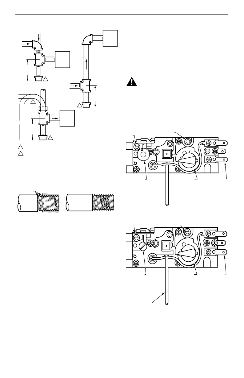
Fig. 1. Sediment trap installation.
TWO IMPERFECT
THREADS
GAS CONTROL
PIPE
GAS
CONTROL
M3077
Pilot Gas Connection
Square off the end of tubing and remove burrs.
1.
Slip compression fitting over tubing. Insert tubing
2.
into pilot outlet connection until it bottoms, slide
fitting into place and turn finger tight. Do not use
jointing compound.
Use a wrench to tighten fitting about 1-1/2 turns
3.
beyond finger tight to shear off the olive.
Connect other end of tubing to pilot burner
4.
according to the manufacturer’s instructions.
WARNING
Fire or Explosion Hazard.
Can cause property damage, severe injury or
death.
Do not bend tubing at gas valve after compression fitting has been tightened, as this may
result in a gas leak at the connection.
OUTLET
PRESSURE
TAP
HI/LO
REGULATOR
INLET
PRESSURE TAP
PILOT
N
O
GAS
CONTROL KNOB
F
F
O
WIRING
TERMINALS
M12670
THREAD PIPE THE AMOUNT
SHOWN IN TABLE FOR
INSERTION INTO GAS CONTROL
Fig. 2. Use moderate amount of pipe compound.
Install Valve (Using Tubing)
Mount valve 0 to 90 degrees, in any direction—
1.
including vertically—from the upright position of
the gas control knob.
Mount the valve so gas flow is in the direction of
2.
the arrow on the side of the valve.
Slip gland and ferrule over tubing.
3.
Insert tubing into inlet/outlet connection until it
4.
bottoms, slide ferrule and gland into place and
turn finger tight. Do not use pipe joint compound.
Use a wrench to tighten gland about 1 turn
5.
beyond finger tight. Refer to Fig. 3 through 5.
APPLY A MODERATE AMOUNT OF
PIPE COMPOUND TO PIPE ONLY
(LEAVE TWO END THREADS BARE).
M3075B
Fig. 3. Top view of gas valve with HI/LO regulator.
F
F
O
PILOT
N
O
RESSURE
EGULATOR
DJUSTMENT
UNDER CAP SCREW)
IEZO SPARKER
Fig. 4. Top view of gas valve with standard
GAS
CONTROL KNOB
regulator.
3 69-1304
WIRING
TERMINALS
M12673
 Loading...