

Page 1

V
V
ideo Recorder
RX180
User Manual
Issue 3 – 03/03 US1I-6228
Page 2

Issue 3 – 03/03 US1I-6228
Page 3

Copyright, Notices, and Trademarks
© Copyright 2000 by Honeywell Inc.
While this information is presented in good faith and believed to be
accurate, Honeywell disclaims the implied warranties of
merchantability and fitness for a particular purpose and makes no
express warranties except as may be stated in its written agreement
with and for its customer.
In no event is Honeywell liable to anyone for any indirect, special or
consequential damages. The information and specifications in this
document are subject to change without notice.
This document was prepared using Information Mapping
methodologies and formatting principles.
Information Mapping is a trademark of Information Mapping Inc.
Windows is a registered trademark of Microsoft Inc.
Modbus is a registered trademark of MODICON, Inc.
The omission of a name from this list is not to be interpreted that the
name is not a trademark.
Video Recorder – User Manual i
Page 4

About This Document
Abstract
This manual describes the installation, configuration, operation, and maintenance of the Video
Recorder.
Warranty
The device described herein has been manufactured and tested for correct operation and is warranted
as follows: The Video Recorder carries an 18 month warranty. This warranty includes immediate
technical assistance and replacement of the defective part or instrument, if necessary.
Honeywell warrants goods of its manufacture as being free of defective materials and faulty workmanship. Contact your local sales office of warranty information. If warranted goods are returned to
Honeywell during the period of coverage, Honeywell will repair of replace without charge those items it
finds defective. The foregoing is Buyer’s sole remedy and is in lieu of all other warranties,
expressed or implied, including those of merchantability and fitness for a particular purpose.
Specifications may change without notice. The information we supply is believed to be accurate and
reliable as of printing. However, we assume no responsibility for its use. While we provide application
assistance personally, through our literature and the Honeywell website, it is up to the customer to
determine the suitability of the product in the application.
Contacts
If you encounter any problem with your video recorder, please contact your nearest Sales Office. (See
the address list at the end of this manual).
An engineer will discuss your problem with you. Please have your complete model
number, serial number, and software version available. Model number and serial
number are located on the chassis nameplate. Software version can be viewed under
Maintenance mode; see Section 8 of this manual.
If it is determined that a hardware problem exists, a replacement instrument or part will be shipped
with instructions for returning the defective unit. Do not return your instrument without authorization
from your Sales Office or until the replacement has been received.
ii Video Recorder – User Manual
Page 5
Symbol Meanings
Symbol What it means
Protective ground terminal. Provided for connection of the protective earth green (green
or green/yellow) supply system conductor.
Functional ground terminal. Used for non-safety purposes such as noise immunity
improvement.
WARNING. Risk of electric shock. This symbol warns the user of a potential shock
hazard where voltages greater than 30 Vrms, 42.4 Vpeak, or 60 Vdc may be accessible.
Failure to comply with these instructions could result in death or serious injury
CAUTION. When this symbol appears on the product, see the user manual for more
information. This symbol appears next to the required information in the manual.
Failure to comply with these instructions may result in product damage.
CE conformity
This product conforms with the protection requirements of the following European Council
Directives: 89/336/EEC, the EMC directive, and 73/23/EEC, the low voltage directive. Do not
assume this product conforms with any other “CE Mark” Directive(s).
Attention
The emission limits of EN 50081-2 are designed to provide reasonable protection against harmful
interference when this equipment is operated in an industrial environment. Operation of this
equipment in a residential area may cause harmful interference. This equipment generates, uses, and
can radiate radio frequency energy and may cause interference to radio and television reception when
the equipment is used closer than 30 meters to the antenna(e). In special cases, when highly
susceptible apparatus is used in close proximity, the user may have to employ additional mitigating
measures to further reduce the electromagnetic emissions of this equipment.
Video Recorder – User Manual iii
Page 6

iv Video Recorder – User Manual
Page 7

Contents
1. INTRODUCTION................................................................................................................ 1
1.1 Video Recorder Overview ...............................................................................................................1
1.2 Specifications..................................................................................................................................2
1.3 Model Selection Guide..................................................................................................................12
2 INSTALLATION.................................................................................................................13
2.1 Warning.........................................................................................................................................13
2.2 Unpacking .....................................................................................................................................14
2.3 Panel mounting the video recorder...............................................................................................15
2.4 Wiring the video recorder..............................................................................................................17
2.5 Terminal connections....................................................................................................................19
3. PROGRAMMING AND OPERATING CONCEPTS AND PROCEDURES........................ 35
3.1 Overview .......................................................................................................................................35
3.2 Quick Start Programming..............................................................................................................35
3.3 Modes of Operation.......................................................................................................................35
3.4 Menu Navigation...........................................................................................................................36
3.5 Button functions ............................................................................................................................41
3.6 Text Entry From External Sources................................................................................................45
3.7 Connecting a keyboard or a barcode reader ................................................................................47
3.8 Installing and removing a floppy disk............................................................................................48
3.9 Definition of Function Blocks.........................................................................................................49
3.10 Components of function blocks.....................................................................................................51
3.11 How to program input parameters ................................................................................................55
3.12 How to program function block parameters..................................................................................58
3.13 How to program a simple configuration ........................................................................................58
3.14 How to program common configurations......................................................................................60
3.15 Data Storage.................................................................................................................................74
4. HOW TO PROGRAM FUNCTION BLOCKS AND FEATURES........................................ 79
4.1 Overview .......................................................................................................................................79
4.2 Programming tips..........................................................................................................................80
4.3 The Program mode menu.............................................................................................................81
4.4 Frequently used programming prompts........................................................................................82
4.5 Set Mode.......................................................................................................................................83
Video Recorder – User Manual v
Page 8

4. HOW TO PROGRAM FUNCTION BLOCKS AND FEATURES..........CONT………………….
4.6 Enter Labels..................................................................................................................................84
4.7 Program Analog Inputs .................................................................................................................87
4.8 Program Control Loops.................................................................................................................90
4.9 Program Analog Outputs ............................................................................................................101
4.10 Program Discrete Inputs .............................................................................................................104
4.11 Program Discrete Outputs ..........................................................................................................105
4.12 Program Calculated Values ........................................................................................................105
4.13 Program Alarms..........................................................................................................................143
4.14 Program Totalizers......................................................................................................................144
4.15 Program Profiles .........................................................................................................................146
4.16 Program Constants.....................................................................................................................147
4.17 Copy Block..................................................................................................................................149
4.18 Program Displays........................................................................................................................150
4.19 Enable Features..........................................................................................................................159
4.20 Program Security ........................................................................................................................160
4.21 Serial Communications ...............................................................................................................161
4.22 Set Clock.....................................................................................................................................162
4.23 Load/Store Configuration............................................................................................................163
4.24 Scan Rate ...................................................................................................................................164
4.25 Select Language .........................................................................................................................165
4.26 Data Storage...............................................................................................................................166
5. SETPOINT PROFILER................................................................................................... 175
5.1 Overview of the Setpoint Profiler ................................................................................................175
5.2 Components of a profile..............................................................................................................178
5.3 Parameters that control a profile’s execution..............................................................................185
5.4 How to set up a profiler ...............................................................................................................189
5.5 How to load and run a profiler.....................................................................................................197
6. ONLINE OPERATIONS USING PRIMARY DISPLAYS.................................................. 209
6.1 Overview .....................................................................................................................................209
6.2 Interacting With Primary Displays...............................................................................................210
6.3 Display Messages and Symbols.................................................................................................217
vi Video Recorder – User Manual
Page 9

7. ONLINE OPERATION USING MENU S.......................................................................... 221
7.1 Overview .....................................................................................................................................221
7.2 Data Storage...............................................................................................................................222
7.3 Access Summaries .....................................................................................................................228
7.4 Data Entry...................................................................................................................................232
7.5 Setpoint Profiles..........................................................................................................................234
7.6 Tune Loop...................................................................................................................................235
7.7 Set Mode.....................................................................................................................................242
7.8 Review Programming..................................................................................................................242
8. MAINTENANCE............................................................................................................. 243
8.1 Overview .....................................................................................................................................243
8.2 Routine Maintenance..................................................................................................................245
8.3 Set Mode.....................................................................................................................................245
8.4 Calibrate Analog Inputs...............................................................................................................245
8.5 AO MODULE calibration .............................................................................................................246
8.6 Off-line Diagnostics.....................................................................................................................247
8.7 Database Services......................................................................................................................248
8.8 Reset Unit ...................................................................................................................................248
8.9 Product Information.....................................................................................................................248
8.10 Mains Frequency.........................................................................................................................248
8.11 Warm Start Time.........................................................................................................................249
8.12 Demo...........................................................................................................................................250
9. DIAGNOSTIC AND ERROR MESSAGES...................................................................... 251
9.1 Diagnostic Messages..................................................................................................................251
9.2 Loop Error Indicators...................................................................................................................254
9.3 Error Messages...........................................................................................................................255
10. PARTS ........................................................................................................................... 259
APPENDIX A........................................................................................................................ 263
SAFETY................................................................................................................................ 265
INDEX................................................................................................................................... 277
SALES AND SERVICE
Video Recorder – User Manual vii
Page 10

TABLES
Table 1-1 Specifications........................................................................................................................................ 2
Table 1-2 Analog Input Accuracy--Linear types .................................................................................................. 7
Table 1-3 Analog Input --Non-linear types........................................................................................................... 8
Table 1-4 Standards ............................................................................................................................................... 9
Table 2-1 Universal Analog Input Board Specifications..................................................................................... 22
Table 3-1 Button Functions................................................................................................................................. 41
Table 3-2 QWERTY Key Equivalents................................................................................................................ 45
Table 3-3 Function Block Types........................................................................................................................... 50
Table 3-4 Function Block Parameter Designators .............................................................................................. 53
Table 3-5 Output Code Connection Procedure................................................................................... ................ 55
Table 3-6 Example Number Selection Procedure Using Front Panel Buttons..................................................... 57
Table 3-7 Example Programming Discrete Input Parameter with a Number....................................................... 57
Table 3-8 Example Function Block Parameter Selection Procedure ................................................................... 58
Table 3-9 Function Block Configuration Procedure........................................................................................... 58
Table 3-10 Example Configuration Procedure..................................................................................................... 59
Table 3-11 Data Storage File Extensions............................................................................................................. 75
Table 4-1 Program Mode Menu........................................................................................................................... 81
Table 4-2 Frequently Used Programming Prompts............................................................................................. 82
Table 4-3 Labels for Function Blocks................................................................................................................. 85
Table 4-4 Other Labels ....................................................................................................................................... 86
Table 4-5 Analog Input Algorithm Selection...................................................................................................... 87
Table 4-6 Standard Algorithm Prompts.............................................................................................................. 87
Table 4-7 Custom Algorithm Prompts................................................................................................................ 89
Table 4-8 Loop Characteristics........................................................................................................................... 90
Table 4-9 Control Loop Type Menu Selections.................................................................................................. 92
Table 4-10 Loop Prompts.................................................................................................................................... 94
Table 4-11 Analog Output Types....................................................................................................................... 101
Table 4-12 Prompts For Analog Output Types.................................................................................................. 101
Table 4-13 Analog Output Prompts.................................................................................................................. 102
Table 4-14 Discrete Input Prompts................................................................................................................... 104
Table 4-15 Discrete Output Prompts................................................................................................................. 105
Table 4-16 CV Types......................................................................................................................................... 106
Table 4-17 Peak Picking Prompts..................................................................................................................... 107
Table 4-18 Signal Select Prompts..................................................................................................................... 108
Table 4-19 Compare Prompts............................................................................................................................ 109
Table 4-20 Compare’s Condition Type and Condition Time Prompts ............................................................. 111
Table 4-21 Counter Prompts............................................................................................................................. 113
Table 4-22 Math Prompts..................................................................................................................................114
Table 4-23 Free Form Math Prompts................................................................................................................ 115
Table 4-24 Free Form Math Functions ............................................................................................................. 116
Table 4-25 Logic Prompts................................................................................................................................. 117
Table 4-26 Logic Operators.............................................................................................................................. 118
Table 4-27 Free Form Logic Prompts ............................................................................................................... 119
Table 4-28 (A OR B) AND C............................................................................................................................ 120
Table 4-29 Results of Logic Equation Using Iteration....................................................................................... 120
Table 4-30 Inverter Prompts............................................................................................................................. 120
Table 4-31 BCD Prompts.................................................................................................................................. 121
Table 4-32 How Profiles Are Saved In Memory .............................................................................................. 122
Table 4-33 Function Generator Prompts........................................................................................................... 123
Table 4-34 Interval Timer Prompts.................................................................................................................... 125
Table 4-35 Periodic Timer Prompts.................................................................................................................. 127
viii Video Recorder – User Manual
Page 11

Table 4-36 Set Up Timer Prompts..................................................................................................................... 127
Table 4-37 Mass Flow Prompts........................................................................................................................ 128
Table 4-38 Carbon Prompts.............................................................................................................................. 129
Table 4-39 Relative Humidity Prompts ........................................................................................................... 131
Table 4-40 F
Sterilization Prompts.................................................................................................................. 132
0
Table 4-41 Advanced Splitter Prompts............................................................................................................... 134
Table 4-42 Standard Splitter Prompts................................................................................................................. 135
Table 4-43 Scaling Prompts.............................................................................................................................. 136
Table 4-44 Signal Clamp Prompts.................................................................................................................... 137
Table 4-45 1 Point Block Average Prompts...................................................................................................... 138
Table 4-46 Rolling Average Prompts................................................................................................................ 139
Table 4-47 Multiple Average Prompts.............................................................................................................. 140
Table 4-48 CEMS Block Average Prompts...................................................................................................... 141
Table 4-49 CEMS Rolling Average Prompts.................................................................................................... 142
Table 4-50 Alarm Prompts................................................................................................................................ 143
Table 4-51 Totalizer Prompts.............................................................................................................................. 145
Table 4-52 Constant Prompts............................................................................................................................ 147
Table 4-53 Copy Block Prompts........................................................................................................................ 149
Table 4-54 Display Setup Procedure................................................................................................................. 152
Table 4-55 Set Up Trend 1 Prompts ................................................................................................................. 152
Table 4-56 Paper Chart Speed Equivalents to Time Base Selections ............................................................... 153
Table 4-57 1 trend group live buffer size............................................................................................................ 154
Table 4-58 2 trend group live buffer size........................................................................................................... 154
Table 4-59 4 trend group live buffer size........................................................................................................... 155
Table 4-60 Set Up Bar Graph 1 Prompts.......................................................................................................... 156
Table 4-61 Set Up Panel Display Prompts........................................................................................................ 156
Table 4-62 Set Up Unit Data Display Prompts................................................................................................. 156
Table 4-63 Set Up Profile Display Prompts...................................................................................................... 156
Table 4-64 Assign Displays To Keys Prompts................................................................................................. 157
Table 4-65 Enable Features Prompts ................................................................................................................ 159
Table 4-66 Security Prompts.............................................................................................................................. 160
Table 4-67 Serial Communications Prompts ...................................................................................................... 161
Table 4-68 Set Clock Prompts.......................................................................................................................... 162
Table 4-69 Load/Store Config Files Prompts....................................................................................................163
Table 4-70 Suggested Scan Rates ...................................................................................................................... 164
Table 4-71 Data Storage Setup Procedure........................................................................................................ 166
Table 4-72 Prompts For Storage Setup Of Trends, Alarms, Events, Diagnostics............................................. 168
Table 4-73 Stored Events.................................................................................................................................. 169
Table 4-74 Unit Data Prompts.......................................................................................................................... 170
Table 4-75 Disk capacity Prompts.................................................................................................................... 172
Table 4-76 Disk Storage Capacity of LS120 or ZIP disk.................................................................................. 173
Table 4-77 Disk Storage Capacity for the 1.44 Mbyte Floppy Disk................................................................... 174
Table 5-1 Example of Segment Events............................................................................................................. 183
Table 5-2 Parameters That Control Profiler Execution..................................................................................... 185
Table 5-3 Program Profiler Prompts................................................................................................................. 190
Table 5-4 Setpoint Profiles Prompts................................................................................................................... 191
Table 5-5 Edit Profile Prompts ......................................................................................................................... 193
Table 5-6 Edit Segments Prompts..................................................................................................................... 196
Table 5-7 How Profiles Are Stored In Memory................................................................................................ 198
Table 5-8 Procedure To Load A Program From Memory Using Online Menu................................................. 199
Table 5-9 Procedure To Load A Program From Memory Using Point/Detail Menu......................................... 199
Table 5-10 How Profiles Are Stored On Disk.................................................................................................. 200
Table 5-11 Disk Program Capacity................................................................................................................... 200
Table 5-12 Procedure To Load A Program From Disk..................................................................................... 201
Video Recorder – User Manual ix
Page 12

Table 5-13 Profiler Starting Procedure............................................................................................................. 202
Table 5-14 Profiler Hold Procedure.................................................................................................................. 203
Table 5-15 Profiler Reset Procedure................................................................................................................. 203
Table 5-16 Profiler Advance Procedure............................................................................................................ 204
Table 5-17 Profiler Shutdown Procedure.......................................................................................................... 204
Table 5-18 Event Viewing Procedure............................................................................................................... 205
Table 5-19 Details Viewing Procedure............................................................................................................. 205
Table 5-20 Summary Viewing Procedure......................................................................................................... 206
Table 5-21 Segment Editing Procedure ............................................................................................................ 207
Table 6-1 Displays Accessed With Display Button.......................................................................................... 209
Table 6-2 Point/Detail Menu Prompts .............................................................................................................. 211
Table 6-3 Stop Panel_4 Display Rotation Procedure........................................................................................ 214
Table 6-4 Resume Panel_4 Display Rotation Procedure.................................................................................. 214
Table 6-5 Interacting With Loop Displays........................................................................................................ 216
Table 6-6 Messages and Symbols at Bottom of Display................................................................................... 218
Table 6-7 Messages and Symbols Elsewhere on Display.................................................................................. 219
Table 7-1 Online Main Menu............................................................................................................................. 221
Table 7-2 Floppy Disk Insertion/Removal Procedure....................................................................................... 222
Table 7-3 Disk Status......................................................................................................................................... 223
Table 7-4 Storage Start/Stop Controls .............................................................................................................. 225
Table 7-5 Data Storage Replay Procedure........................................................................................................ 226
Table 7-6 Alarm Acknowledgment Procedure................................................................................................... 229
Table 7-7 Diagnostic Acknowledgment Procedure............................................................................................ 230
Table 7-8 Delete All Diagnostics Procedure..................................................................................................... 231
Table 7-9 Tune Loop Prompts........................................................................................................................... 235
Table 7-10 Stages Of Pretune ............................................................................................................................ 238
Table 7-11 Pretune STOPPED Prompts............................................................................................................. 238
Table 7-12 Pretune IDENTIFYING & CALCULATING Prompts.................................................................. 239
Table 7-13 Pretune COMPLETE Prompts......................................................................................................... 240
Table 7-14 Pretune Abort Messages .................................................................................................................. 241
Table 8-1 Maintenance Mode Menu................................................................................................................. 243
Table 8-2 Calibrate Analog Output Procedure................................................................................................... 247
Table 8-3 Offline Diagnostic Prompts............................................................................................................... 247
Table 8-4 Database Services Prompts............................................................................................................... 248
Table 9-1 Diagnostic Error Messages................................................................................................................ 251
Table 9-2 Internal Error Messages.................................................................................................................... 252
Table 9-3 Abnormal Loop Conditions And Indicators...................................................................................... 254
Table 9-4 Error Messages................................................................................................................................. 255
Table 10-1 Parts................................................................................................................................................ 259
Table A-1 Security Bypass Procedure ...............................................................................................................263
x Video Recorder – User Manual
Page 13

Figures
Figure 1-1 Video Recorder .............................................................................................................................. 1
Figure 1-2 Video Recorder Model Number................................................................................................. 10
Figure 2-1 AI Board Terminal Block Connections...................................................................................... 22
Figure 2-2 10 ohm Copper Connections ..................................................................................................... 22
Figure 2-3 DI Board Terminal Block Connections...................................................................................... 23
Figure 2-4 AO Board Terminal Block Connections.................................................................................... 24
Figure 2-5 DO Board Terminal Block Connections.................................................................................... 25
Figure 2-6 DO Board Relay Contact Setting............................................................................................... 26
Figure 2-7 RS232 wiring configur at ion......................................................................................................... 29
Figure 2-8 RS422 wiring configuration ........................................................................................................ 30
Figure 2-9 RS422 Interface Connections.................................................................................................... 30
Figure 2-10 RS485 wiring configurat ion ........................................................................................................ 32
Figure 2-11 Interface connector ..................................................................................................................... 32
Figure 3-1 Video Recorder Front Door Buttons.......................................................................................... 36
Figure 3-2 Menu Navigation Guide Through ON LINE, PROGRAM, and MAINTENANCE mode
MAIN MENUs............................................................................................................................... 37
Figure 3-3 ON LINE mode MAIN MENU ...................................................................................................... 38
Figure 3-4 PROGRAM mode MAIN MENU.................................................................................................. 39
Figure 3-5 MAINTENANCE mode MAIN MENU ......................................................................................... 40
Figure 3-6 Connection of a keyboard or a barcode reader........................................................................ 47
Figure 3-7 Alarm 1 Function Block Components......................................................................................... 51
Figure 3-8 Example Input Parameter Connection....................................................................................... 55
Figure 3-9 Function Block Connection Format............................................................................................ 56
Figure 3-10 Example Configuration................................................................................................................ 59
Figure 3-11 Control Of Furnace Zone Temperature With 4-20 mA (CAT) Control Signal ..................... 60
Figure 3-12 Basic Function Blocks Required For Control Configuration Of Figure 3-11........................ 61
Figure 3-13 Labeling Each Function Block’s Name And Major Inputs And Outputs............................... 62
Figure 3-14 Labels For Internal Function Bl oc k Parameters...................................................................... 63
Figure 3-15 Interconnections Between Function Blocks............................................................................. 62
Figure 3-16 Complete Function Block Diagram Of Figure 3-11................................................................. 64
Figure 3-17 Control Of Wastewater pH Using A Time Proportioning (DAT) Control Signal .................. 65
Figure 3-18 Function Block Diagram Of Figure 3-17................................................................................... 65
Figure 3-19 Temperature Control Of Water Using Split Output Or Duplex Control ................................ 66
Figure 3-20 Function Block Diagram Of Figure 3-19................................................................................... 67
Figure 3-21 Temperature Control Of An Oil Heated Chemical Reaction Chamber ................................ 68
Figure 3-22 Function Block Diagram Of The Cascade Control Strategy.................................................. 69
Figure 3-23 Example Set Point Prof ile........................................................................................................... 70
Figure 3-24 Function Block Diagram Of Set Point Profile Control Of Figure 3-16 .................................. 71
Figure 3-25 Discrete Inputs Controlling Execution Of Set Point Profiler Function Block ....................... 71
Figure 3-26 Up To 16 Discrete Events May Be Programmed Per Step Of A Set Point Profile............. 72
Figure 3-27 Tying A Profile Function Block’s Discrete Events With Discrete Output Hardware ........... 73
Figure 3-28 Categories of Stored Data.......................................................................................................... 74
Figure 4-1 Function Block Configuration of a Typical Ratio Control Loop ....................................... 100
Figure 4-2 Compare Signal Flow...................................................................................................... 109
Figure 4-3 Compare’s Greater Than Result, With Hysteresis.......................................................... 110
Figure 4-4 Math CV Feedback Programming................................................................................... 114
Figure 4-5 Logic Signal Flow............................................................................................................ 116
Figure 4-6 Free Form Logic Signal Flow.......................................................................................... 119
Figure 4-7 Function Generator Curve .............................................................................................. 123
Video Recorder – User Manual xi
Page 14

Figure 4-8 Function Generator Configuration For Valve Characterization....................................... 124
Figure 4-9 Function Generator Configuration For Input Signal Characterization............................. 124
Figure 4-10 Periodic Timer................................................................................................................. 126
Figure 4-11 Typical Carbon Potential Control Configuration.............................................................. 130
Figure 4-12 Advanced Splitter (Default Outputs) .............................................................................. 133
Figure 4-13 Heat/Cool Configuration................................................................................................. 133
Figure 4-14 Standard Split Output Function...................................................................................... 135
Figure 4-15 CEMS Rolling Average .................................................................................................. 142
Figure 4-16 Example of Constant Destination................................................................................... 148
Figure 4-17 Displays Accessible by the Display Buttons (continued)............................................... 150
Figure 5-1 Setpoint Profiler Schematic..................................................................................................... 176
Figure 5-2 Single and Multi-phase Profiles.............................................................................................. 177
Figure 5-3 Value/Duration Ramp Type..................................................................................................... 178
Figure 5-4 Time Ramp Type ...................................................................................................................... 179
Figure 5-5 Rate Ramp Type....................................................................................................................... 180
Figure 5-6 External Ramp Type................................................................................................................. 181
Figure 5-7 Guaranteed Soak and Hysteresis ........................................................................................... 182
Figure 5-8 Activating Events In Mid-Segment .......................................................................................... 183
Figure 5-9 Example Of A Segment Loop .................................................................................................. 184
Figure 5-10 Hot Start...................................................................................................................................... 186
Figure 5-11 Fast Forward............................................................................................................................... 187
Figure 5-12 Shutdown .................................................................................................................................... 188
Figure 5-13 Allowable and Non-All o wable Pro gram Storage................................................................... 192
Figure 5-14 Buttons ........................................................................................................................................ 197
Figure 6-1 Changing Profile Batch Tag ..................................................................................................... 210
Figure 6-2 Horizontal and Vertical Trend Displays .................................................................................. 211
Figure 6-3 Vertical Trend at 2X Zoom........................................................................................................ 213
Figure 6-4 Panel Display.............................................................................................................................. 214
Figure 6-5 Loop Displays............................................................................................................................. 215
Figure 6-6 Example of Primary Display..................................................................................................... 217
Figure 7-1 Data Storage Status Display.................................................................................................... 226
Figure 7-2 Control Loop Tuning Display.................................................................................................... 237
Figure 8-1 AO Module Jumper ST1 ............................................................................................................ 246
xii Video Recorder – User Manual
Page 15
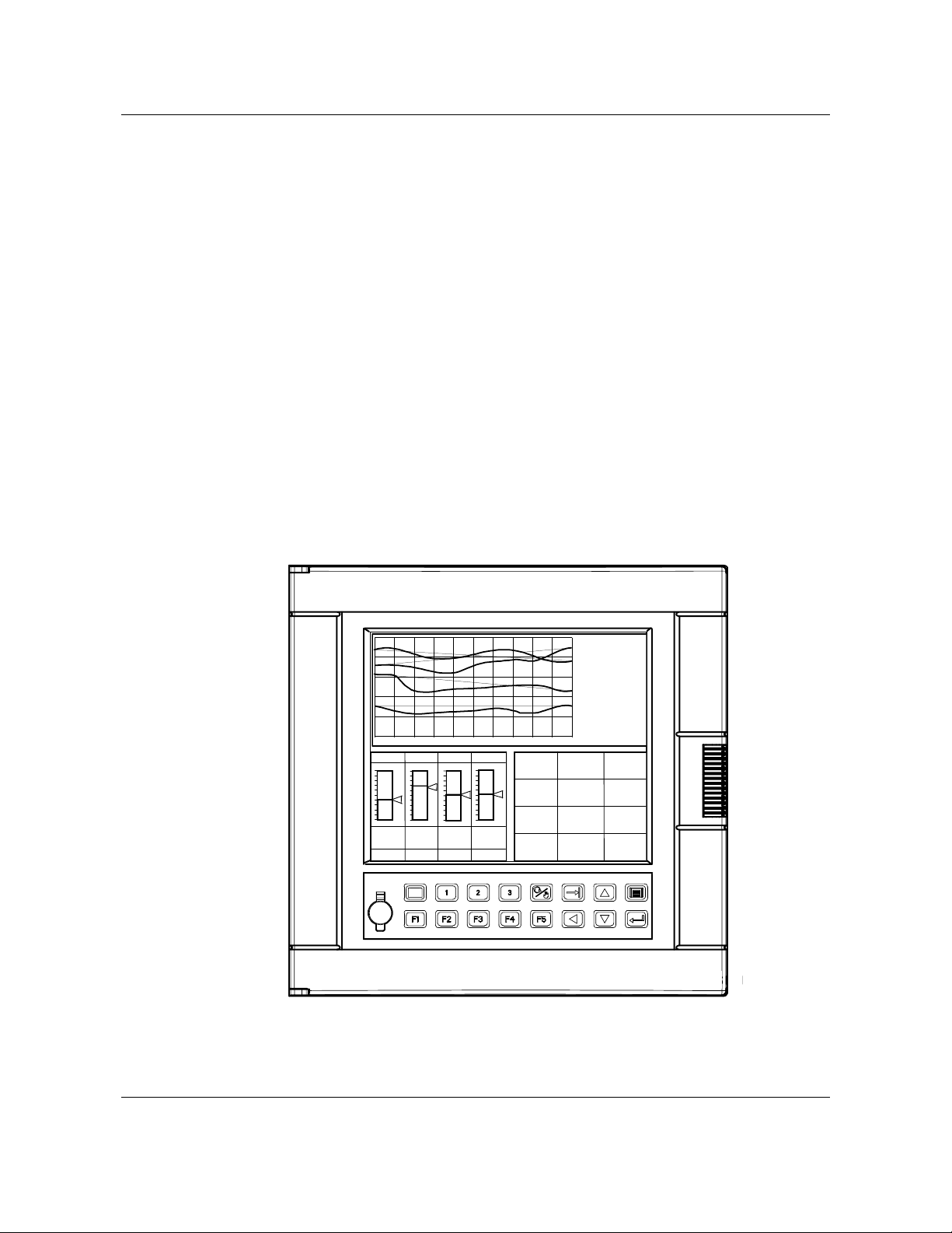
1.1 Video Recorder Overview
The Video Recorder (Figure 1-1) is part of the family of multi-point, multi-function video products. The
instrument offers display versatility, flexible data storage, up to 8 control loops, each one can run its own
profile, and advanced math functions. This integration of several functions eliminates the need for
multiple devices and reduces installation costs.
The instrument features a high resolution LCD display which is capable of displaying up to 16 different
colors simultaneously. The front door opens to allow access to a 100MB ZIP disk drive. A mini DIN
connector can be used on the front door for connecting a PC keyboard or barcode reader for easy
labeling of parameters. Barcode reader also stores Event Records to disk.
Sixteen panel keys control all functions of the instrument, including configuration.
The instrument will accept thermocouple, RTD, pyrometer, milliamp, millivolt and volt inputs. Up to eight
analog outputs are available for retransmission or control. Data can be directed to various display
formats, stored on floppy disk, or read from an optional serial communications link. Analog and discrete
data can be displayed in trend or tabular format. Viewed data can be either “live” (real time inputs) or
historical (retrieved from disk).
Flexible modular design and several options make this instrument adaptable to nearly any industrial
application.
Introduction
1. Introduction
TAG1
TAG7
VALUE1
VALUE7
TAG2
TAG8
VALUE2
VALUE8
TAG3
TAG9
VALUE3
VALUE9
TAG4
TAG10
VALUE4
VALUE10
TAG5
TAG11
VALUE5
VALUE11
TAG6
TAG12
VALUE6
VALUE12
LP1
1000.00
0.00
PV 405.00
SP 405.00
OUT 15 .0
A S1
LP2
1500.00
1054.00
1040.00
10.0
M S2
0.00
LP3
1200.00
623.00
622.00
5.0
M S1
LP4
ZONE1
ZONE2
2400.00
123.45
DEG F
ZONE4
123.45
DEG F
ZONE7
0.00
0.00
1266.00
1244.00
5.0
A S1
123.45
DEG F
ZONEA
123.45
DEG F
123.45
DEG C
ZONE5
123.45
DEG F
ZONE8
123.45
DEG C
ZONEB
123.45
DEG
ZONE3
123.45
DEG F
ZONE6
123.45
DEG C
ZONE9
123.45
DEG F
ZONEC
123.45
DEG F
Figure 1-1 Video Recorder
Video Recorder - User Manual 1
Page 16

Introduction
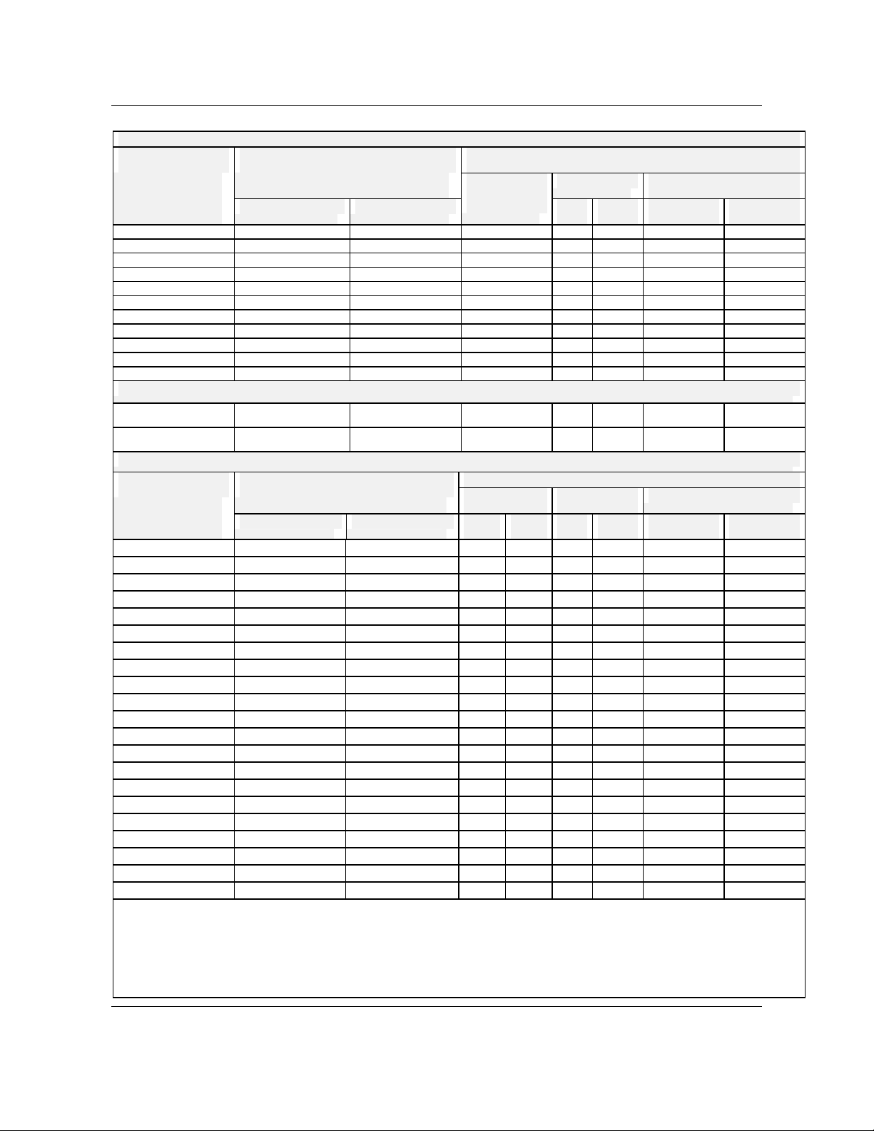
1.2 Specifications
Table 1-1 Specifications
Physical
Enclosure Metal case and rugged die cast aluminium door and frame. High impact resistant
polycarbonate keypad and glass or polycarbonate window. IP55 rating (NEMA 3) from front
panel.
Mounting (Panel) 40 mm thickness (max.) (1,57")
Dimensions Compact size: 320 mm (12.60") depth
310 mm front face height x 317 mm width (12.21" x 12.48")
278 mm x 278 mm (10.95" x 10.95") cutout
Weight 14 kg, depending on configuration (30 lbs)
I/O Ports Standard PC keyboard Connector (6 pin mini DIN type) - on front panel. May be used to connect to a
QWERTY keyboard or to an ASCII Barcode Reader.
Environmental
Temperature
Altitude < 2000 meters
Installation
Category
Pollution Degree 2
Power Universal power supply, 100 to 240 Vac/dc, 100 VA max.
Fuse Rating 3.15 Amps, 250 Vac slow blow
Display
Keys 16 membrane switches.
Data Archiving
Setpoint
programmers
Operating: 5 to 40°C (41 to104°F).
Storage: -20 to 60°C (-4 to 158°F).
Relative Humidity: 10 to 90%, non-condensing at 40°C.
II
Attributes
Type: Color LCD active matrix.
Screen Size: 10.4" diagonal.
Resolution: 640 x 480 pixels.
Update Rate: 1 second.
Trend Timebase: 5 min. to 24 hrs/screen; 0.5 cm/hr to 154 cm/hr vertical (0.2"/hr to 61"/hr
vertical), 0.8 cm/hr to 250 cm/hr horizontal (0.3"/hr to 100"/hr horizontal).
Media: 100MB ZIP disk drive.
Data Types: Analog points, calculations, discrete status, alarms, diagnostics.
Trends: 4 max. (up to 12 points max. per trend)
Unit Data: 1 (up to 12 points, 10,000 records)
Alarm History: Up to 1600 records
Event History: Up to 1600 records
Diagnostic History: Up to 1600 records
Setpoint Programs: 224 maximum on LS120 floppy disk.
Storage Rate Range: 0.25 to 3600 sec.
Capacity: Automatically calculates storage time based on storage rate.
Up to 4
Video recorder – User Manual 2
Page 17

Table 1-1 Specifications (continued)
Program Capability
Introduction
Number of
Programs
Number of
Segments
Ramping Capability
Ramp Time Range
Soak
Soak time range
Program Cycling
Startup/Shutdown
Memory can store 96 programs for a single channel programmer, 48 programs for a dual
channel programmer, 32 programs for a three channel programmer, and 24 for a four
channel programmer. Programs can also be stored to floppy disk. Programmer has ability
to start a program at a predetermined time.
63 segments per profile
Ramp X - Ramp rate is set by specifying x degrees per second, per minute, or per hour.
Ramp T - Ramp rate is set by selecting the time to go from previous setpoint to next
setpoint in t time.
Ramp E - Ramp rate is set to increment by ∆SP for every pulse of a digital input.
Value Duration Ramp - Ramp rate is based on the start value of the ramp and the time
specified to reach the next soak start value.
0-9,999,999 hours, minutes, or seconds.
Guaranteed or non-guaranteed. Can be applied to ramp or soak segment or across entire
profile/program.
0-9,999,999 hours, minutes, or seconds.
Entire programs or portions of a program can be cycled up to 99 times. Loops can be
nested up to 4 deep.
Can be set up to use a predefined startup profile separate from the normal processing
programs. Shutdown profile can be attached to the end of a profile and can be jumped to
for emergency shutdown.
PV Hot Start
Batch Programming
Profile Events
Can start the profile at the point where the present PV value first intersects the profile.
1 to 255 Batch numbers. Batch number is assigned by the programmer and is incremented
automatically when batch is started.
Using a keyboard or bar code reader and the front keyboard connector, a batch can be
labeled with a name of up to 8 characters.
Up to 16 events can be defined in each segment of a profile. Each event’s state is
activated at the beginning of the segment and is held throughout the segment.
Video Recorder - User Manual 3
Page 18

Introduction
Table 1-1 Specifications (continued)
Universal Analog Inputs
Number 4 per module, up to 12 modules per video recorder
Input Types mV, V, mA, T/C, RTD, pyrometers
Signal source Thermocouple with cold junction compensation
Line resistance up to 1000 ohms, T/C, mV, mA, V
RTD, 3-wire connections, 40 ohms balanced maximum
Input Impedance 10 megohms for T/C and mV inputs; >1 megohm for volt inputs
Input Isolation 400 Vdc point-to-point
1350 Vac RMS A/D converter to logic
Stray rejection Series mode >60 dB. Common mode at 120 Vac >130 dB.
Burnout T/C, Pyrometry configurable to upscale, downscale or none.
Linear types: none except following ranges:
Volt: -500 to 500 mV; -1 to 1V; -2 to 2V; -5 to 5V; 0 to 10V; -10 to 10V; inherent to
zero volt
RTD: Inherent upscale
mA: Inherent downscale
T/C Break Detection Via current pulse
Scan rate Fastest rate:
250 ms up to 4 inputs, 500 ms up to 12 inputs, 750 ms up to 16 inputs,
1s up to 24 inputs,1,5 s up to 28 inputs, 2 s up to 44 inputs, 3 s up to 48 inputs.
A/D Converter Resolution Better than 1 part in 50,000 at 50 Hz.
Better than 1 part in 41,667 at 60 Hz.
Analog Outputs
Number 4 per module (non-isolated), up to 2 modules per video recorder (8 outputs)
Type Current output configurable within 0 to 20 mA. Maximum load 400 ohms per output.
Voltage output configurable 0 to 5 V.
Isolation from ground 350 Vac
Accuracy Factory configured accuracy = 0.1% at reference conditions
Field calibration accuracy = 0.05%
Temperature Effects 0.1% per 10°C in the rated limits
D/A Resolution 16 bits
Digital Inputs
Number 6 per module, up to 6 modules per
video recorder
Input Voltage Range 80 to 264 Vac 10.2 to 26.4 Vdc
Peak Voltage 264 Vac 26.4 Vdc
AC Frequency 47 to 63 Hz N/A
Isolation from ground 2300 Vac/1 min. 1100 Vac/1 min.
Isolation between inputs 350 Vac 30 Vac
ON Voltage Level 75 Vac minimum 9.5 Vdc minimum
OFF Voltage Level 20 Vac maximum 3.5 Vdc maximum
AC Inputs DC Inputs
6 (sink/source) per module, up to 6 modules
per video recorder
Video recorder – User Manual 4
Page 19

Introduction
Table 1-1 Specifications (continued)
Input Impedance 51K 5.6K
Input Current 0.9 mA @ 100 Vac 1.1 mA @ 12 Vdc
3.2 mA @ 24 Vdc
Minimum ON Current 0.3 mA 0.3 mA
Maximum OFF Current 0.15 mA 0.2 mA
Base Power Required* 50 mA maximum 50 mA maximum
OFF to ON Response 5 to 30 ms 1 to 8 ms
ON to OFF Response 10 to 50 ms 1 to 8 ms
Logic Inputs
Number 6 (dry contact) per module, up to 6 modules per video recorder
Isolation from ground 2300 Vac/1 min.
Switching Voltage 5 Vdc
Switching Current 5 mA
Digital Outputs
Number 6 per module, up to 6 modules per video
recorder. Only 1-5 on each module can
be configured as DAT outputs.
Operating Voltage 15 to 264 Vac 10.2 to 26.4 Vdc
Output Type SSR (Triac) NPN open collector
Peak Voltage 264 Vac 40 Vdc
AC Frequency 47 to 63 Hz N/A
Isolation from ground 2300 Vac/1 min. 1100 Vac/1 min.
Isolation between outputs 350 Vac 30 Vac
ON Voltage Drop <1.5 Vac (>0.1A)
<3.0 Vac (<0.1A)
Maximum Load Current 0.5A per point 0.3A per point
Maximum Leakage Current 4 mA (264 Vac, 60 Hz)
1.2 mA (100 Vac, 60 Hz)
0.9 mA (100 Vac, 50 Hz)
Maximum Inrush Current 10A for 10 ms 1A for 10 ms
Minimum Load 10 mA 0.5 mA
Base Power required* 20 mA/ ON pt. 250 mA
maximum
OFF to ON Response 1 ms 1 ms
ON to OFF Response 1 ms +1/2 cycle 1 ms
Fuses (European type 5 x
20mm)
Number 6 per module, up to 6 modules per video recorder. Only 1-5 on each module can be
Contact Rating 2A, 250 Vac on resistive load
Isolation from ground 2300 Vac/1 min.
Isolation between outputs 2300 Vac/1 min.
Contact Type SPST normally open (NO), individually configurable to normally closed (NC) via
* Base Power Required is the power required to provided module operation within specifications.
1 per output, 1.0A slow blow 1 per output
configured as DAT outputs.
jumper
AC Outputs DC Outputs
6 (current sinking) per module, up to 6
modules per video recorder. Only 1-5
on each module can be configured as
DAT outputs.
1.5 Vdc maximum
0.1 mA @ 40 Vdc
120 mA maximum
5V
1A fast blow
Relay (Alarm) Outputs
Video Recorder - User Manual 5
Page 20

Introduction
Table 1-1 Specifications (continued)
Time Proportional Outputs (TPO) on digital output
Time Resolution Equals the Scan Cycle time of the recorder.
Module Only Digital outputs 1 to 5 can be configured as DAT outputs.
Synchronization Individual TPOs are not synchronized with others.
Performance/Capacities
Math Calculations Standard Math package includes: 24 Calculated Values along with the following Math
functions: Free Form Math, Math Operators (+, -, x, ÷, Absolute Value, Square Root, Std.
Deviation), Free Form Logic, Logic Operators (AND, OR, XOR, Inverter, Flip Flop, OneShot), Inverter algorithms.
Constants 32
Alarms 96
Totalizers 0, 4 or 48
Control Loops Up to 8 (PID, ON/OFF, Cascade, Split, Ratio).
Auto Tune Each loop can be pre-tuned automatically to establish acceptable tuning parameters. On-
Primary Displays Up to 10 displays may be assigned from the 32 formats selected among trend screens,
Support Displays 13 (menu access).
Communications
(optional)
Advanced Math package includes: 64 Calculated Values with the functions from Standard
Math along with the following types of pre-packaged algorithms: Signal Select, Compare,
Signal Clamp, Periodic Timer, Interval Timer, Counter, Relative Humidity, Standard Splitter,
Scaling.
line fuzzy overshoot suppression.
Bargraph screens, Panel screens, Summary screens, loop screens, Setpoint profiler
screens.
Type: RS-422/485, Modbus RTU protocol
Connection: 2 or 4 wire RS485.
Distance: 600 meters, (2000 feet).
Number of links: Up to 30
Baud Rate: 1200, 2400, 4800, 9600, 19.2K, 38.4K.
Parity: Selectable; odd, even, none.
Video recorder – User Manual 6
Page 21

Accuracy
Accuracy
Rated limits and
associated drifts
Reference conditions
Parameters Rated limits Influence on accuracy
Temperature
Supply voltage
Source resistance
RTD 0.1°C per Ohm in each wire
Humidity
Long-term stability
Table 1-2 Analog Input Accuracy--Linear types
Millivolts Volts Current Ohms
0 to 10 mV
-10, +10 mV
0 to 20 mV
-20, 0, +20 mV
0, 50 mV
-50, 0, +50 mV
10 to 50 mV
0 to 100 mV
-100, 0, +100 mV
0 to 500 mV
-500, 0, +500 mV
NOTE:
- The mA inputs must be connected to a 250 ohms resistor across the input terminals.
Table 1-1 Specifications (continued)
Analog input accuracy and rated limits
Temperature = 23°C ± 2°C (73°F ± 3°F)
Humidity = 65% RH ± 5%
Line voltage = Nominal ± 1%
Source resistance = 0 ohm
Series mode and common mode = 0 V
Frequency = Nominal ± 1%
Field calibration accuracy 0.05% of the selected range (IEC 873)
Factory calibration: 0.1%
Cold junction accuracy: ± 0.5°C
0 to 50°C (32 to 120 °F) 0.15% per 10°C of change (See
85 to 250 V No influence
T/C, mV 6 µV per 400 Ohms of line
10 to 90% RH at 25°C 0.1% max.
0.1% per year
0 to 1 V
-1, 0, 1 V
0 to 2 V
-2, 0, +2 V
0 to 5 V
-5, 0, +5 V
1 to 5 V
0 to 10 V
-10, 0, +10 V
0, 20 mA
4, 20 mA
Introduction
Note A)
Cold junction 0.3°C/10°C
resistance max. = 1000 Ohms
balanced leads
40 Ohms max. (from 0 to 400°C)
0 to 200
0 to 2000
Video Recorder - User Manual 7
Page 22
Introduction
Table 1-3 Analog Input --Non-linear types
Thermocouples -ITS-90 except where noted
Type
% Range
°F °C
J 0 to 2190 -18 to 1199 0.1 0.4 0.2
K 0 to 2500 -18 to 1371 0.1 0.4 0.2
E -450 to 1830 -268 to 999 0.1 0.4 0.2
T -300 to 752 -184 to 400 0.1 0.4 0.2
N 0 to 2372 -18 to 1300 0.1 0.6 0.3
B 110 to 3300 43 to 1816 0.1 2.5 1.4 752 to 3300 400 to 1816
R 0 to 3210 -18 to 1766 0.1 1.5 0.8
S 0 to 3210 -18 to 1766 0.1 1.6 0.9
W5/W26 (3)
PLAT II (3)
NI-NIMO 32 to 2502 0 to 1372 0.1 0.4 0.2
0 to 4200 -18 to 2316 0.1 0.9 0.5 32 to 3272 0 to 1800
-100 to 2500 -73 to 1371 0.1 0.4 0.2
RTD (4)
CU10 -100 to 310 -73 to 154
PT100 IEC -300 to 1570 -184 to 854 0.1 0.5 0.3
0.5 2.5 1.4
Pyrometry (Rayotube & Spectray) Types
Type
Operating span
Max value Min value
°F °C
18890-0035 1200 to 2600 649 to 1426 4 2 1 0.6
18890-0073 800 to 1800 427 to 982 12.5 7 1 0.6
18890-0074 1100 to 2300 594 to 1260 3 1.7 1 0.6
18890-0075 1500 to 3300 816 to 1815 6 3 1.8 1
18890-0163 200 to 1000 94 to 537 11 6 1.5 0.8
18890-0216 2110 to 4600 1155 to 2537 8 4.4 1.8 1
18890-0412 1375 to 3000 747 to 1648 10 5.6 1.3 0.7
18890-00643 1850 to 4000 1010 to 2204 8 4.4 1 0.6
18890-1729 1650 to 3600 899 to 1982 5 3 1.5 0.8
18890-3302 750 to 1600 399 to 871 6 3 1 0.6
18890-5423 2210 to 5000 1210 to 2760 18 10 2 1.1
18894-0579 752 to 2552 400 to 1400 33 18 3.6 2
18899-8814 340 to 1800 172 to 982 11 6 2 1.1
18894-9014 752 to 2552 400 to 1400 20 11 2.6 1.4
Spectray 18885 1832 to 3452 1000 to 1900 30 17 0.6 0.3
Spectray 18885-1 1292 to 2912 700 to 1600 60 33 0.6 0.3
Spectray 18885-2 806 to 1400 430 to 760 38 21 0.2 0.1
Spectray 18886 1833 to 3452 1001 to 1900 20 11 0.6 0.3
Spectray 18886-1 1292 to 2912 700 to 1600 80 44 0.6 0.3
18874-0578 752 to 2552 400 to 1400 3.6 2 1.8 1
18875-0579 752 to 2552 400 to 1400 3.6 2 1.8 1
°F °C °F °C
NOTES:
1: The accuracy will be the larger value between Min Value and %range of the selected limits
2: Reference range = operating range when blank
3: IPTS-68
4: T° influence: 0.5% per 10°C on Cu 10 ohms, 0.3% per 10°C on Pt 100 ≤ 200°C
5: For Pyrometry, the worst accuracy (Max value) is at the low range limit , the best (Min value) is at the high limit.
- For non linear temperature transmitter, the transmitter range MUST be identical to the input range of the recorder.
Accuracy (1) Operating span
Min value
Reference range (2)
°F °C °F °C
Accuracy ( 5 )
Video recorder – User Manual 8
Page 23

Introduction
Table 1-4 Standards
This product is designed and manufactured to be in conformity with applicable U.S., Canadian, and International
(IEC/CENELEC/CE) standards for intended instrument locations. The following Standards and Specifications are
met or exceeded.
Case Protection IP55 on front door only, when the instrument is panel mounted and the front door
securely closed.
Rear of Panel EN 60529, IP 20
Flammability Rating UL 94 - V2
Vibration Level 10 to 40 Hz, 0.07 mm displacement; 40 to 60 Hz, 0.2g acceleration
Electromagnetic
Compatibility
Safety IEC1010 Installation Category II for personal protection
Intended Instrument
Locations
CE EMC Directive 89/336/EEC
Rack or panel mounting in control room or industrial environments (operator
accessibility front of panel only)
Installation Category II with grounded mains supply from isolation transformer or GFI
(ground fault interrupter)
Pollution Degree 2 with rear of panel enclosed, in industrial environment
Video Recorder - User Manual 9
Page 24

Introduction
g
g
g
g
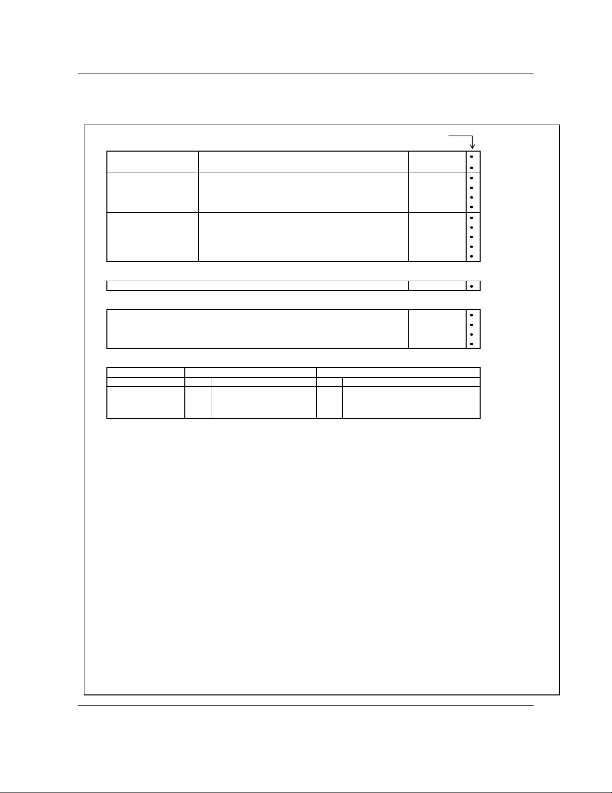
1.3 Model Selection Guide
This table helps you to identify correctly the unit in front of you. Please refer to the product label and
verify that you have the right unit.
Select the desired key number. The mark to the right shows the selection available. A complete model
number has the requested number of digits from each table as follows.
Video Recorder Model Number Figure 1-2 Video Recorder Model Number
Instructions
Key Number I II III IV V VI
KEY NUMBER Selection Availability
Description
Video Recorder VRX180
TABLE I - ANALOG INPUTS
Analog Universal Inputs 4 Universal Analog Inputs 04
TABLE II - ADDITION AL INPUTS AND OUTPUTS
Make the desired selection from Tables I to VI .
The arrow to the right marks the selection available.
A dot ( ) denotes unrestricted availability.
VRX180 - _ _ - _ _ _ _ _ _ - _ _ _ _ _ - _
-
_ _ _ _ _ _
-_ _
( slot A to F ) 8 Universal Analog Inputs 08
12 Universal Analog Inputs 12
16 Universal Analog Inputs 16
20 Universal Analog Inputs 20
24 Universal Analog Inputs 24
Slot J 4 Universal Analog Inputs A _ _ _ _ _
Slot K 4 Universal Analog Inputs _A _ _ _ _
Slot L 4 Universal Analog Inputs _ _ A _ _ _
Slot M 4 Universal Analog Inputs _ _ _ A _ _
None 0 _ _ _ _ _
6 Digital Inputs ( contact closure) B _ _ _ _ _
6 Di
ita l Inputs 24 Vdc C _ _ _ _ _
6 Digital Inputs 120 / 240 Vac E _ _ _ _ _
6 Relays Outputs R _ _ _ _ _
6 Digital O utputs 24 Vdc ( open collector) G _ _ _ _ _
6 Digital O utputs 120 / 240 Vac ( triac ) H _ _ _ _ _
None _0 _ _ _ _
6 Digital Inputs ( contact closure) _B_ _ _ _
ita l Inputs 24 Vdc _C_ _ _ _
6 Di
6 Digital Inputs 120 / 240 Vac _E _ _ _ _
6 Relays Outputs _R_ _ _ _
6 Digital O utputs 24 Vdc ( open collector) _G_ _ _ _
6 Digital O utputs 120 / 240 Vac ( triac )
None _ _ 0 _ _ _
6 Digital Inputs ( contact closure) _ _ B _ _ _
6 Di
ita l Inputs 24 Vdc _ _ C _ _ _
6 Digital Inputs 120 / 240 Vac _ _ E _ _ _
6 Relays Outputs _ _ R _ _ _
6 Digital O utputs 24 Vdc ( open collector) _ _ G _ _ _
6 Digital O utputs 120 / 240 Vac ( triac )
None _ _ _ 0 _ _
6 Digital Inputs ( contact closure) _ _ _ B _ _
6 Di
ita l Inputs 24 Vdc _ _ _ C _ _
6 Digital Inputs 120 / 240 Vac _ _ _ E _ _
6 Relays Outputs _ _ _ R _ _
6 Digital O utputs 24 Vdc ( open collector) _ _ _ G _ _
6 Digital O utputs 120 / 240 Vac ( triac )
_H_ _ _ _
_ _ H _ _ _
_ _ _ H _ _
Video recorder – User Manual 10
Page 25

Model Selection Guide (cont.)
g
g
g
)
Introduction
TABLE II - ADDITIONAL INPUTS AND OUTPUTS (continued)
Slot N 4 Universal Analog Inputs _ _ _ _ A _
Slot P 4 Universal Analo g Inputs _ _ _ _ _ A
TABLE III - FIRMWARE - DATA STORAGE
Control Lo ops 1 Control Loop 1 _ _ _ _
(Notes 1, 5) 2 Control Loops 2 _ _ _ _
Set Point Programs 1 Set Point Program _ 1 _ _ _
(Note 4) 2 Set Point Programs _ 2 _ _ _
Math Standard Math _ _ 0 _ _
(Note 2) Advance Math _ _ 1 _ _
Da ta s tora
Other None
TABLE IV - COMMUNICATION
Comm unication None 0
e (Note 6
TABLE V - OPTIONS
Docum entatio n English E _ _ _ _ _
(prompts langua ge, F rench F _ _ _ _ _
manual) German G _ _ _ _ _
English - (U.S. form at) U _ _ _ _ _
Certificates None _ 0 _ _ _ _
Tagging Non e _ _ 0 _ _ _
None _ _ _ _ 0 _
6 Digital Inputs ( contact closure) _ _ _ _ B _
6 Di
ital Inputs 24 Vdc _ _ _ _ C _
6 D ig ital In p u ts 1 2 0 / 24 0 V a c _ _ _ _ E _
6 Relays Outputs _ _ _ _ R _
6 Digital Outputs 24 Vdc ( open collector) _ _ _ _ G _
6 Digital Outputs 120 / 24 0 Vac ( triac ) _ _ _ _ H _
4 C u rre nt Ou tp u ts
None _ _ _ _ _ 0
6 Digital Inputs ( contact closure) _ _ _ _ _ B
ital Inputs 24 Vdc _ _ _ _ _ C
6 Di
6 Digital Inputs 120 / 240 Vac _ _ _ _ _ E
6 Relays Outputs _ _ _ _ _ R
6 Digital Outputs 24 Vdc ( open collector) _ _ _ _ _ G
6 Digital Outputs 120 / 24 0 Vac ( triac ) _ _ _ _ _ H
4 C u rre n t O u tp u ts
None 0 _ _ _ _
4 Control Loops 4 _ _ _ _
6 Control Loops 6 _ _ _ _
8 Control Lo ops
None _ 0 _ _ _
3 Set Point Programs _ 3 _ _ _
4 Set Point Programs
Advance Math and 4 Totalizers _ _ 2 _ _
Advance Math and 48 Totalizers
100 Mb Z IP Drive
RS485 - Modbus RTU C
Eth ern e t In te rfa c e E c
Ita lian I _ _ _ _ _
Spanish S _ _ _ _ _
Certificate of C onformance _ B _ _ _ _
C a libr a tio n C ert ificate
Calibration and Conformance Certificates
Linen _ _ L _ _ _
Stainless steel
(No te 7 )
(No te 3 )
(No te 3 )
VRX180
Sele c tion
_ _ _ _ M _
_ _ _ _ _ M
8 _ _ _ _
_ 4 _ _ _
_ _ 3 _ _
_ _ _ 2 _
_ _ _ _ 0
_ C _ _ _ _
_ E _ _ _ _
_ _ S _ _ _
Video Recorder - User Manual 11
Page 26
Introduction
(
)
p
g
p
y
g
Model Selection Guide (cont.)
TABLE V - OPTIONS (continued)
Approvals CE Mark Compliant _ _ _ 0 _ _
Software None _ _ _ _ 0 _
Case Galvanized Case, Grey Door, Glass Window, Latch _ _ _ _ _ 0
TABLE VI
Factory Use Only 00
SOFTWARES AND SUPPORT PARTS Part #
SDA Data Analysis Software (can be ordered separately if not selected in Table V) 045501
SCF Configuration Software (can be ordered separately if not selected in Table V) 045502
SDI Di sk In itia liza tio n S o ftw a re
Kit of 4 resistors 250 Ohms for 4-20 mA in
RESTRICTIONS
Restriction Letter Available With Not Available With
c
Notes:
1. The available algorithms include: P ID (standard and advance), Cascade, Split O utput and On/Off.
The appropriate outputs from Table I must be specified - Current or Relays.
If Split (Duplex) output Control is required, adv ance math must be selected ( Table III ).
2. Standard Math includes 24 Calculated Values and the following pre-packaged algorithms
Free Form Math Logic Operators Flip-Flop/One Shot Periodic Tim er
Free Form Logic Math Operators Invertor
Advance Math includes 64 Calculated Values and the followin
Signal Select Interval Timer Counter
Compare R elative Humidity Scaling
Signal Clamp Mass Flow Advanced Splitter
Peak Picking Fo Calculation Continuous Emissions Monitoring
Function Generator Multi
Carbon Potential Single Point Average - CEM Rolling Average
Rolling Average Standard Splitter
3. Customer must supply Input Actuation Type and Range for each input for inclusion in the free form
section of the Factor
based on the factory default ranges.
4. When selectin
5. When selecting Control loops, make sure to select outputs (as necessary in Table II)
6. Provided with each VRX180 are : one pre-initialized disk and one SDI software pack.
SDI software should be installed on a PC and used for initialization of new disks.
7. Must purchase Table II _ _ _ _ M _ in order to select Table II Selection _ _ _ _ _ M.
CSA/NRTLc/CE Mark
SDA and SCF _ _ _ _ B _
SCF (Configuration Software) _ _ _ _ C _
SDA
Data A n a lysis Software
Galvanized Case, Grey Door, Glass Window, Key Lock _ _ _ _ _ 1
Galvanized Case, Grey Door, Plastic Window, Latch _ _ _ _ _ 2
Galvanized Case, Grey Door, Plastic Window, Key Lock _ _ _ _ _ 3
Portable Case (Painted Case, Handles)
(Not e 6 )
ut 46181080-503
Table Selection Table Selection
le Input Average - CEM Block Average
order to supply the Custom Calibration Certificate, otherwise the calibration will be
SP program make sure to select analog output (current) as necessary (Table II slot N,P).
_ _ _ _ _ A, _ _ _ _ _ B, _ _ _ _ _ C,
II
_ _ _ _ _ E, _ _ _ _ _ R, _ _ _ _ _ G,
_ _ _ _ _ H, _ _ _ _ _ M
additional of pre-package algorithms.
VRX180
Selection
_ _ _ C _ _
_ _ _ _ E _
_ _ _ _ _ 6
46193351-501
Video recorder – User Manual 12
Page 27
2. Installation
What’s in this section?
The following topics are covered in this section.
Topic Page
Warning 13
Unpacking 14
Panel mounting the video recorder 15
Wiring the video recorder 17
Terminal connections 19
NOTICE
If this instrument is used in a manner not specified by the manufacturer, the protection provided by the
instrument may be impaired.
2.1 Warning
Installation
To avoid the risk of electrical shock which could cause personal injury, follow all safety notices in
this documentation.
Protective earth terminal. Provided for connection of the protective earth supply system conductor.
• POWER SUPPLY
Ensure the source voltage matches the supply voltage of the video recorder before power on.
(In the rear of the video recorder, near to the connector of the power supply)
• PROTECTIVE GROUNDING
Make sure to connect the protective grounding to prevent an electric shock before power on.
Do not operate the instrument when protective grounding or fuse might be defective.
To avoid a potential shock hazard, never cut off the internal or external protective grounding
wire or disconnect the wiring of protective grounding terminal.
• FUSE
To prevent a fire, make sure to use the appropriate fuse (current, voltage, type). Before
replacing the fuse, turn off the power and disconnect the power source. Do not use a different
fuse or short-circuit the fuse holder.
• DO NOT OPERATE IN AN EXPLOSIVE ATMOSPHERE
Do not operate the instrument in the presence of flammable liquids or vapors. Operation of any
electrical instrument in such an environment constitutes a safety hazard.
• NEVER TOUCH THE INTERIOR OF THE INSTRUMENT
Inside this instrument, there are areas of high voltage; therefore, never touch the interior if the
power is connected. This instrument has an internal changeable system; however, internal
inspection and adjustments should be done by qualified personnel only.
• If the equipment is used in a manner not specified by the manufacturer, the protection
provided by the equipment may be impaired.
• Do not replace any component (or part) not explicitly specified as replaceable by your supplier.
• INSTALL INDOOR ONLY.
Video Recorder - User Manual 13
Page 28
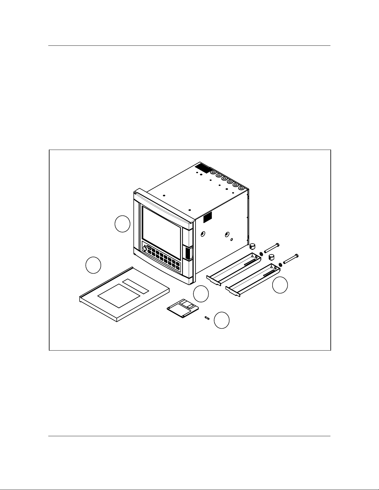
Installation
2.2 Unpacking
Examine the shipping container carefully. If there are visible signs of damage, notify the carrier and your local
sales office immediately.
If there is no visible damage, compare the contents with the packing list. Notify your local sales office if there is
equipment shortage.
To obtain proper credit and to avoid delays, return goods only after contacting your local sales office in
advance.
Carefully remove the instrument and remove any shipping ties or packing material. Follow the instructions on
any attached tags or labels and then remove such tags or labels.
4
5
2
1
1. Fuse (spare) use only 3.15 AT (slow blow) fuses size 5 x 20 mm
2. Floppy disk
3. Mounting brackets with nuts
4. Video recorder
5. Product manual
NOTE: In the event that any items are missing, please contact your nearest sales office.
3
Video Recorder - User Manual 14
Page 29
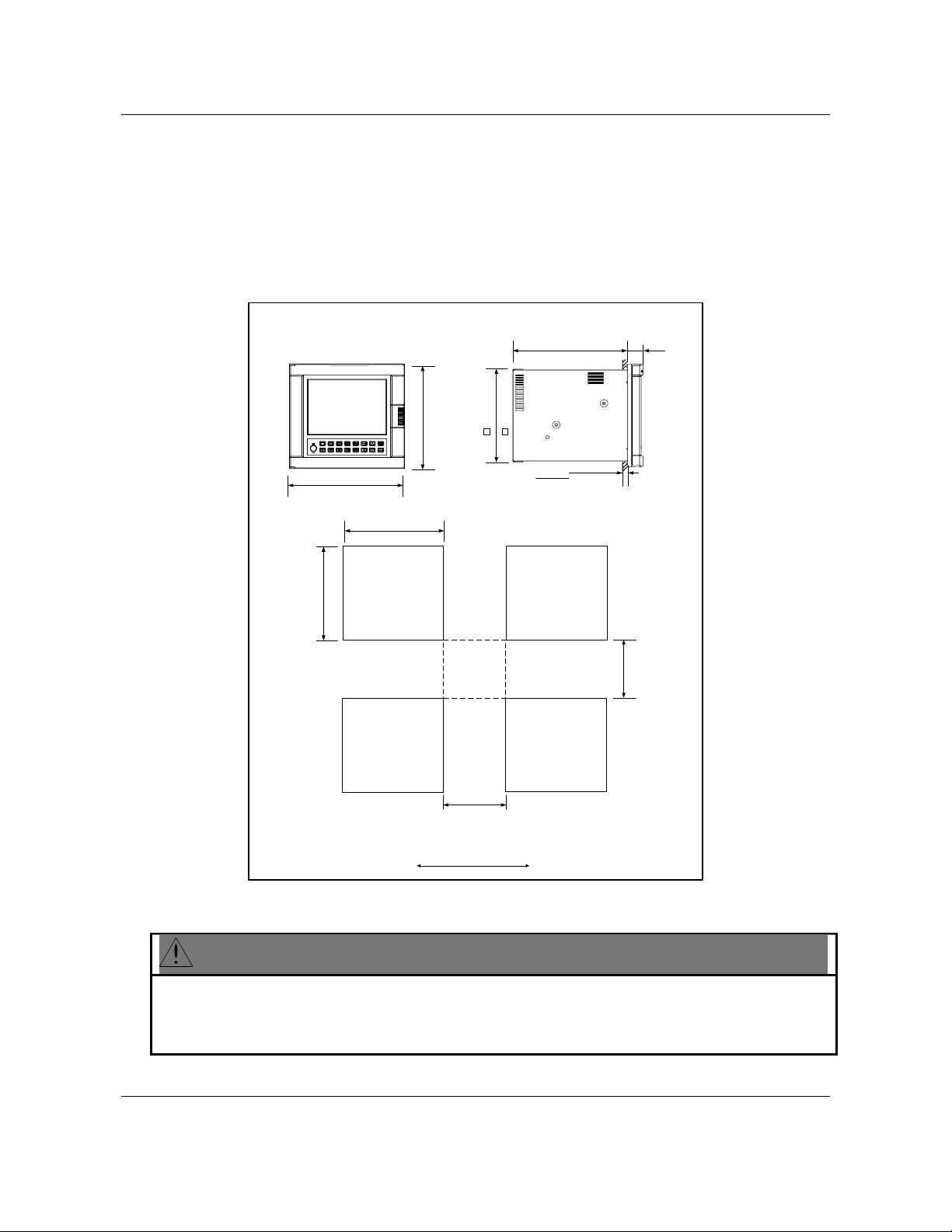
Installation
2.3 Panel mounting the video recorder
2.3.1 Recommendations
This video recorder is designed to operate under specific conditions. If you need more information, refer to the
product specification sheet.
2.3.2 External dimensions and cut-out
Prepare panel cut-out as detailed below:
+1.5
278
320
12.60
275
310
12.21
317
12.48
+1.5
0
278
0
+0.06
10.95
0
0
+0.06
0
10.95
10.83
40 max.
1.55
45
1.77
> 3
> 75
> 75
> 3
millimeters
inches
NOTE: Maximum panel thickness 40 mm (1.55")
CAUTION
The maximum temperature inside the cabinet should not exceed the ambient conditions specific for the
video recorders.
The video recorder must be mounted into a panel to limit operator access to the rear terminals.
Failure to comply with these instructions may result in product damage.
Video Recorder - User Manual 15
Page 30
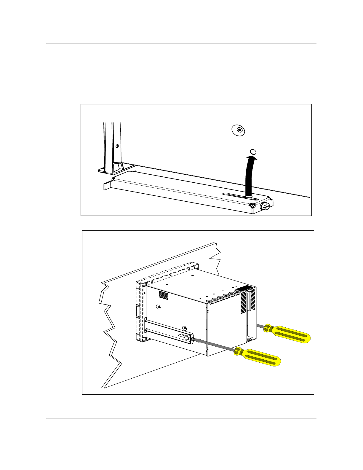
Installation
2.3.3 Installing the video recorder
To install the video recorder, follow the figure below:
Step 1: Remove rear cover and wire access holes
Step 2: Insert video recorder through the panel cutout
Step 3: Attach mounting brackets to the sides of the video recorder
Bracket position
Step 4: Tighten the mounting screws
Mounting brackets
Video Recorder - User Manual 16
Page 31

NOTE: When installing the video recorder, the following limits should be respected:
Mounting angle limits
+ 15 Deg
- 15 Deg
Installation
2.4 Wiring the video recorder
2.4.1 Recommendations
CAUTION
• All wiring must be in accordance with local electrical codes and should be carried out by authorized and
experienced personnel.
• The ground terminal must be connected before any other wiring (and disconnected last).
• A switch in the main supply is mandatory near the equipment.
• If an external fuse is used to protect the electrical circuit to the video recorder, the fuse should match the
video recorder fuse rating (fuse type) as well as for the fuseholder.
• Sensor wiring should be run as far as possible from power wiring. (motors, contactors, alarms, etc.)
• To reduce stray pick-up, we recommend the use of a twisted pair sensor wiring.
• EMI effects can be further reduced by the use of shielded cable sensor wiring. The shield must be
connected to the ground terminal.
Failure to comply with these instructions may result in product damage.
Video Recorder - User Manual 17
Page 32

Installation
• EXAMPLE:
Rep. A: Cable retaining bracket (46210075-501)
Rep. B: Grounding screw
Rep. C: Clamp
Rep. D: Shielded cable (inputs)
Rep. E: External grounding cable
• The use of spade terminals on all wiring is recommended.
A
C
E
B
A
A
D
Video Recorder - User Manual 18
Page 33

Installation
2.5 Terminal connections
2.5.1 Rear cover
The rear cover protects the I/O boards terminal connectors. On the rear cover, a drawing reminds the user of the
terminals use.
Positions
AI = Analog input
AO = Analog output
DI = Digital input
DO = Digital output (relay)
Note: Terminal blocks can be removed from the board for easier wiring and board replacement.
From A to F + J to P (Upper and lower rack)
From N to P (Upper rack)
From J to P (Upper rack)
From J to P (Upper rack)
Video Recorder - User Manual 19
Page 34

Installation
Removing the rear cover grants access to the terminals location:
Step A: Turn off power
Step B: Loosen screws holding rear cover
B
Step C: Slide rear cover to the left
Video Recorder - User Manual 20
C
Step D: Remove rear cover
Page 35

2.5.2 Inserting and extracting inputs and outputs board:
Steps A and B show how to insert or extract a board from the video recorder.
To extract a board: Step A then Step B.
To insert a board: Step B then Step A.
Step A
Installation
1
2
1
(1) Press down on terminal block clips
(2) Push in or pull out to insert or remove from board
Step B
Push in or pull out on the board to insert or remove from video recorder
Video Recorder - User Manual 21
Page 36

Installation
g
2.5.3 Analog input boards
A universal Analog Input board accepts a variety of input signals from field devices.
Figure 2-1 illustrates the terminal block connections for the various inputs. One AI board can be
configured to accept multiple input types.
Table 2-1 Universal Analog Input Board Specifications
Specification Description
Input Types mV, V, mA, T/C, RTD, and Ohms
Number of Inputs 4 per board, up to 12 boards per video recorder (48 inputs)
Signal Source Thermocouple with cold junction compensation, for operation
between 0 to 80º C (32 to 176º F)
Line resistance up to 1000 ohms, T/C, mV, mA, V
RTD, 3-wire connections, 40 ohms balanced max.
Input Impedance
Therm ocouple input
+
-
Ground Terminal
mV, V
mV or V
source
G rou nd T erm ina l G rou nd T erm ina l
Grounded lead of
RTD should be
connected to RTD
terminal of VRX
terminal block
10 Meg Ω for T/C, mV inputs,
> 1 Meg Ω for volt inputs
Slot ID
Inpu ts
+
-
T/C, m V, V
C urrent Input m A
4 to 20
mA
Source
G round T erm inal
*
A 250 ohm resistor is required for the
input range
RTD Input (3 wires)
RTD
+
*
-
+
-
Figure 2-1 AI Board Terminal Block Connections
10 ohm Copper
with common
round lead
-
+
RTD
-
+
RTD
12
+
11
-
10
1
+
9
-
8
7
+
6
-
RTD
RTD
5
4
3
+
2
-
1
All RTD connections are
common on Universal AI
board.
C hannel 4
C hannel 3
C hannel 2
C hannel 1
Figure 2-2 10 ohm Copper connections
Video Recorder - User Manual 22
Page 37

2.5.4 Digital Inputs Boards
Three types of Digital Input (DI) boards accept three types of input signals.
1. Logic Input
2. DC Input
3. AC Input
Each type is described on the following pages.
DI boards. See Section 1 for details on all I/O board specifications.
Contact Closure
Installation
Figure 2-3 shows the terminal block connections for all
SLOT ID
12
DI 6
11
10
Logic input
24 VDC
DC input
120/240 VAC
AC input
Figure 2-3 DI Board Terminal Block Connections
2.5.5 Analog Outputs
The Analog Output (AO) board provides four outputs at 0 to 20 mA (configurable for 4 to 20 mA or any
span between 0 to 20 mA). When not used for an analog output, an output channel may be used to
power a transmitter with 24 Vdc power. The video recorder will support up to two AO boards, for a total
of eight outputs.
on all I/O board specifications.
Figure 2-4 shows the terminal connections for the AO board. See Section 1 for details
L1
L2
9
DI 5
8
DI 4
7
+
-
6
DI 3
5
4
DI 2
3
2
DI 1
1
Video Recorder - User Manual 23
Page 38

Installation
4 to 20 mA output
Slot ID
+
Load
-
Ground Terminal
+
24V
-
NOTE - Channels not used as analog outputs can be used
to supply a transmitter with 24 Vdc power
.
Figure 2-4 AO Board Terminal Block Connections
12
11
10
9
8
7
6
5
4
3
2
1
Channel 4
2
Channel 3
Channel 2
Channel 1
2.5.6 Digital Outputs
There are three types of Digital Output (DO) boards which provide three types of Off/On control.
1. Relay (alarm) Output
2. DC Output
3. AC output
Figure 2-4 shows the terminal block connections for the DC output and AC output DO boards. See
Section 1 for details on all I/O board specifications.
Video Recorder - User Manual 24
Page 39

Installation
Figure 2-5 DO Board Terminal Block Connections
The Digital Output board with relay outputs contain jumpers to set the de-energized state of the relay
contacts. The relays are factory set to Normally Closed (NC) for each output on the relay output board,
To change the state of the contacts: See
of needle-nose pliers and move the jumper from the location NC (normally closed ) to the location NO
(normally open).
Figure 2-6 DO Board Relay Contact Setting. Use a pair
Video Recorder - User Manual 25
Page 40

Installation
Digital
Output Board
NC6
S6
N
O
NC5
N
O
NC4
N
O
NC3
N
O
NC2
N
O
NC1
N
O
S5
6
S4
S3
S2
5
S1
12
11
10
!
9
8
4
3
2
1
7
6
5
4
NO NC
3
2
1
NO
Normally Open
Contacts
NC
Normally Closed
Contacts
Figure 2-6 DO Board Relay Contact Setting
2.5.7 Wiring communications
This software package has been designed to operate with three kinds of serial communication
standards which are: RS232, RS422 and RS485. Refer to the following chapters for the wiring
configuration of each of them. For more details on the wiring, please refer to your computer product
manual.
Video Recorder - User Manual 26
Page 41

2.5.7.1 RS232 wiring configuration
Installation
2.5.7.1.1 Switch configuration
VIDEO RECORDER
Figure 2-7 RS232 wiring configuration
RS232
3
2
1
LEFT
away from PC board
RIG HT
towa rd PC b o a rd
Video Recorder - User Manual 27
Page 42

Installation
2.5.7.1.2 Interface connector
• With DB9 connector
Interface cable connectors pin arrangement and signal functions.
VIDEO RECORDER SIDE
1 2 3 4 5 6 7 8 9 10 11 12 13
14 15 16 17 18 19 20 21 22 23 24 25
DB25 male connector face view
5 4 3 2 1
DB9 female connector face view
PC SIDE
9 8 7 6
RECORDER PC
Pin n° Pin n°
2 2
3 3
5 4
7 5
20 6
20 8
Note
: Check compatibility with your PC as far as no standard for DB9 connector exists yet.
VIDEO RECORDER
PC
1 DCD
Video Recorder - User Manual 28
2
3
7
2 RD
3 TD
4 DTR
5 S.G.
6 DSR
7 RTS
8 CTS
Page 43

• With DB25 connector
Interface cable connectors pin arrangement and signal functions.
Installation
VIDEO RECORDER SIDE
1 2 3 4 5 6 7 8 9 10 11 12 13
14 15 16 17 18 19 20 21 22 23 24 25
DB25 male connector face view
VIDEO RECORDER PC
Pin n° Pin n°
3 2 to video recorder transmitted DATA
2 3 from video recorder received DATA
- 4 from DTE request to send
- 5 to DTE clear to send
7 7 - ground
VIDEO RECORDER
PC SIDE
13 12 11 10 9 8 7 6 5 4 3 2 1
25 24 23 22 21 20 19 18 17 16 15 14
DB25 female connector face view
Direction Description
PC
2
3
7
2 TD
3 RD
4 RTS
5 CTS
6 DSR
7 S.G.
8 DCD
20 DTR
Video Recorder - User Manual 29
Page 44

Installation
2.5.7.2 RS422 wiring configuration
VIDEO RECORDER VIDEO RECORDER
2.5.7.2.1 Switch configuration
away from PC board
VIDEO RECORDER
Figure 2-8 RS422 wiring configuration
RS422
3
2
1
LEFT
RIG HT
towa rd PC b o a rd
Video Recorder - User Manual 30
Page 45

2.5.7.2.2 Interface connector
Installation
TOP SIDE
RXA (-)
RXB (+)
TXA (-)
TXB (+)
BOTTOM SIDE
Figure 2-9 RS422 Inferface connections
2.5.7.3 RS485 (2 wires) wiring configuration
VIDEO RECORDER VIDEO RECORDER
VIDEO RECORDER
Figure 2-10 RS485 wiring configuration
Video Recorder - User Manual 31
Page 46

Installation
2.5.7.3.1 Switch configuration
RS485
3
2
1
2.5.7.3.2 Interface connector
LEFT
away from PC board
TOP SIDE
BOTTOM SIDE
RIGHT
toward PC board
RX/TXA (-)
RX/TXB (+)
Video Recorder - User Manual 32
Figure 2-11 Interface connector
Page 47

Installation
2.5.7.4 Connecting the RS422/485 link to a computer
The VRX180 video recorder with the RS422/485 Communications option can be connected your
computer using one of two arrangements :
• Wired to an RS422/485 compatible serial port (if the computer is equipped with such a port).
• Wire the RS232 serial port of the computer to an RS232 to RS485 converter. The RS485 port
of the converter should be wired to the Communications port of the VRX recorder.
Arrangement
ICS plug-in I/O board
Description
Wired directly to the RS422/485 port in your computer using an ICS plugin I/O board which is specifically designed to interface with the IBM (or
IBM compatible) PC, PC/XT; or PC/AT computer.
This board is available from...
ICS Computer Products, Inc.
5466 Complex Street
Suite 208
San Diego, California 92123
Burr-Brown Converter Using the RS232 port a Burr-Brown RS232 to RS422/485 converter
installed between the RS232 port and the video recorder.
This converter is available from :
Burr-Brown
International Airport Industrial Park
P.O. Box 11400
Tucson, Arizona 85734
Part number LDM485ST, limited distance modem
Westermo converter The Westermo MA44 converts RS232 to RS422/485. It is installed
between the RS232 port and the video recorder.
2.5.7.5 Rear connection
The video recorder has built in circuits to reduce the effects of most electrical noise. We recommend
that you review the following guidelines, to minimize the noise effects.
1. Separate the communication leadwires from the line voltage, the alarm output, contactors, motors etc...
2. For a communication distance, over 1.5 meters, use a separate metal tray, or metal conduit.
3. Use wiring cable composed of twisted pair wirings, with a shield for RS485 and RS422. Use a shielded
cable for RS232.
4. Connect the shield wire to the ground, at one end only, preferably at the video recorder. Use for example
a wiring cable type: Belden 9271 twinax, or equivalent.
5. We recommend to install a 120 ohms resistor between TXA and TXB, on the last video recorder on
communication link.
6. The maximum capabilities are:
Type of communication Distances max. # of Unit
RS232 15 meters / 50 feet 1
RS422 1000 meters / 3280 feet 15
RS485 1200 meters / 4000 feet 31
Video Recorder - User Manual 33
Page 48

Installation
Video Recorder - User Manual 34
Page 49

Programming and Operating Concepts
3. Programming and Operating Concepts and Procedures
3.1 Overview
This section explains the instrument’s programming and operating concepts and procedures. Read and
understand this section before attempting to program and operate your instrument.
3.2 Quick Start Programming
Use this section to quickly start up your instrument. This section contains the basic concepts you should
know for configuring the instrument. For more details on specific topics, you should refer to section 4 and
5 of this manual.
Step Action See
1 To program analog inputs Section 4.7 Program Analog Inputs
2 To program control (if your
application has control)
3 To configure displays Section 4.18 Program Displays
4 To configure data storage Section 4.26 Data Storage
5 To program other functions Remaining sections in
Section 3.14 How to program common configurations
Section 4.8 Program Control Loops
Section 5 Setpoint Profiler (if your instrument has a setpoint profiler)
Section 4.9 Program Analog Outputs
Section 4 How To Program Function Blocks and Features
3.3 Modes of Operation
The instrument has three modes of operation: Program, Online, and Maintenance. Each mode has its
own menus. Most menu items provide access to sub-level menus. The SET MODE item switches the
instrument from one mode to another. Your instrument may have reduced menus if options are not
present.
Program mode
Program Mode is an off-line mode for programming (configuring) the instrument. In this mode, all inputs
and outputs are frozen. If any of the five relays are assigned as DAT outputs the recorder will stop
pulsing them when it is placed into Program Mode. The outputs will remain frozen in their present state,
either On or Off.
Online Mode
Online Mode enables full use of the instrument with its inputs, outputs and internal programming. In this
mode, it is fully interactive with all externally connected elements.
Maintenance Mode
Maintenance Mode is an off-line mode for maintaining proper and complete functioning of the instrument.
Functions include calibration, off-line diagnostic testing, and various setups for operation. In
Maintenance Mode, all inputs and outputs are frozen. If any of the five relays are assigned as DAT
outputs the recorder will stop pulsing them when it is placed into Maintenance Mode. The outputs will
remain frozen in their present state, either On or Off.
Video Recorder – User Manual 35
Page 50

Programming and Operating Concepts
3.4 Menu Navigation
Moving between the Program, Online, and Maintenance modes of the instrument is accomplished
through use of the instrument’s Menu, Up Arrow, Down Arrow, and Enter keys located on its front door.
Refer to Figure 3-1.
LP1
LP2
1000.00
1500.00
0.00
PV 405.00
1054.00
SP 405.00
1040.00
OUT 15 .0
10.0
A S1
M S2
TAG1
TAG2
TAG3
TAG4
TAG5
TAG6
TAG7
VALUE7
TAG8
VALUE8
TAG9
VALUE9
TAG10
VALUE10
TAG11
VALUE11
TAG12
VALUE12
ZONE3
123.45
DEG F
ZONE6
123.45
DEG C
ZONE9
123.45
DEG F
ZONEC
123.45
DEG F
VALUE1
VALUE2
VALUE3
VALUE4
VALUE5
VALUE6
LP4
ZONE1
LP3
2400.00
1200.00
623.00
622.00
5.0
M S1
0.00
0.00
1266.00
1244.00
5. 0
A S1
0.00
123.4 5
DEG F
ZONE4
123.45
DEG F
ZONE7
123.45
DEG F
ZONEA
123.45
DEG F
ZONE2
123.45
DEG C
ZONE5
123.45
DEG F
ZONE8
123.45
DEG C
ZONEB
123.45
DEG
Display
F1
Display 1
Display 2
F2
F3
Display 3
F4
Auto/
Manual
F5
Left
Arrow
Tab
Down
Arrow
Up
Arrow
Figure 3-1 Video Recorder Front Door Buttons
Menu
Enter
Video Recorder – User Manual 36
Page 51

Programming and Operating Concepts
A more detailed explanation of the function of each button appears in Section 3.5.
To develop a feel for navigating between modes, power up the instrument and perform the sequence of
steps that follows.
Upon powering up the instrument for the very first time, the logo display will initially appear. Press the
Menu button several times until the ON LINE, PROGRAM, or MAINTENANCE mode MAIN MENU is
displayed. Refer to Figure 3-2. Note: Menus are shown with all possible options; your menu may not
have all options.
PRODUCT
INFO
S/N YXXXX XXXXX XXXXX X
PART NUMBER
Product Info Display
46900052-001
VER SION X.X
DEMO
ACCESS SUMMARIES
TUNE LOOP
PROFILE RS
DATA ENTRY
SETPOINT PROFILES
CONSTANTS
LANGUAGE
OFF-LINE DIAGNOSTICS
DATABASE SERVICESRESET UNITPRODUCT INFORMATIONMAINS FREQUENCY
MAIN MENU - ONLINE
MAIN MENU - PROGRAM
MAIN MENU - MAINTENANCE
SETMODE ONLINE
REVIEW PROGRAMMIN G
PROGRAM LABELS ANALOG INPUTS CONTROL LOOPS
SETMOD E
CALCULATED VALUES DISCRETE OUTPUTS DISCRETE INPUTS ANALOG OUTPUTS
ALARMS TOTALIZERS
SERIAL COMMUNICATIONS SECURITY FEATURES DISPLAYS
COPY BLOCK CLOCK LOAD/STORE CONFIG SCAN RATE
SETMODE MAINTENANCE
WARM START TIME
DATA STORAGE
SET ANALOG OUTPUTS
CALIBRATE ANALOG INPUTS CALIBRATE ANALOG OUTPUT S
Figure 3-2 Menu Navigation Guide Through ON LINE, PROGRAM, and MAINTENANCE
mode MAIN MENUs.
Once you have established which MAIN MENU you are on, use the Up Arrow and Down Arrow buttons
to verify each MAIN MENU choice as indicated in Figure 3-2.
Use the Up Arrow and Down Arrow buttons to find and highlight the menu’s SET MODE prompt.
When the SET MODE prompt is highlighted, press the Enter button.
Use the Up Arrow or Down Arrow buttons to switch the instrument to one of the other two instrument
modes and press the Enter button.
Video Recorder – User Manual 37
Page 52

Programming and Operating Concepts
Once within the mode selected in Step 5, scroll through the mode’s MAIN MENU using the Up Arrow and
Down Arrow buttons. Verify each menu choice as indicated in Figure 3-2.
Repeat Steps 3 through 6 for the last of the three mode selections possible.
Having completed the preceding exercise, changing the instrument’s mode should now be a simple task.
Furthermore, a fundamental understanding of how the Menu, Up Arrow, Down Arrow, and Enter buttons
work should now be at your fingertips.
Now use the Menu, Up Arrow, Down Arrow, and Enter buttons to verify the ON LINE, PROGRAM, and
MAINTENANCE mode sub-level menus detailed in Figure 3-3, Figure 3-4 and Figure 3-5. The sub-level
menus shown represent only the first sub-level below each mode’s MAIN MENU. There are several sublevel menus, not indicated here, that run further below each first sub-level. Note that once inside of a
sub-level menu, regardless of how “deep” the level is, a press of the Menu button will return you to the
next highest menu level. In case you get lost within a mode’s sub-level menu, keep pressing the Menu
button until the ON LINE, PROGRAM, or MAINTENANCE mode MAIN MENU appears on screen.
Be advised that Figure 3-2 through Figure 3-5 comprise a basic “road map” for navigating the menus
within the programmer’s three modes. Sections 4 through 8 of this manual will provide detailed
descriptions of each menu choice and complete guides through all the sub-level menus that run below
the levels indicated in these Figures.
ATTENTION
The following menus contain all possible options. Your instrument may not include some items shown here.
MAIN MENU - ON LINE
SET MODE ON LINE
DATA STORAGE
ACCESS SUMMARIES
DATA ENTRY
SETP OINT PROF ILES
TUNE LOOP
SET ANAL OG OUTPUT S
REVIEW PROGRAMMING
PROFILES
CONSTANTS FEATURES
ENABLE STORAGE
DISPLAY ALARM
SUMMARY
EDIT ALARM
SETPOINTS
EDIT PROFILE #1 EDIT PROFILE #2 EDIT PROFILE #3 EDIT PRO FILE #4
LOOP #1 LOOP #2 LOOP #3 LOOP #4
OUTPUT #1 OUTPUT #2 OUTPUT #3
ANALOG INPUTS ANALOG O UTPUTS DISCRETE INPUTS
DISPLAYS
DATA STOR AGE STA TUS
DISPLAY ALARM
HISTORY
EDIT CONSTANTS
CONTROL LOOPS
ALARMSTOTALIZERS
REPLAY FROM
DISPLAY
DIAGNOSTICS
FORC E DISCRETE
INPUTS
CALCULATED
VALUES
SECURITY
DISK
FORC E DISCRETE
INITIALIZE DISK LIST DISK FILES
DISPLAY ALL
ANALOGS
OUTPUTS
DISPLAY ALL
DISCRETES
ADJUST ANALOG
INPUTS
STOR E PROGRAM
TO DISK
. . .
OUTPUT #4
DISCRETE OUTPUTS
SERIAL COMMUNICATIONS
. . .
SCAN RATE
SET UP NEW
SCHEDULES
DELETE ALL
DIAGNOSTICS
RESET
TOTALIZERS
STOR E PROGRAM
TO MEMORY
LOOP #8
OUTPUT #8
REVIEW CURRENT
SCHEDULES
PRODUCT
INFO RMATI ON
RESET ALL
TOTALIZERS
LOAD PROGRAM
FROM DISK
LOAD PROGRAM
FROM MEMORY
WARNING
BATCH STATEBATC H NUMBER
SET ANAL OG
OUTPUTS
LEVEL
Figure 3-3 ON LINE mode MAIN MENU
Video Recorder – User Manual 38
Page 53

Programming and Operating Concepts
MAIN MENU - PROGRA M
SET MO DE PRO GRAM
LABELS
ANALO G INP UTS
CONT ROL LO OPS
ANAL OG OUT PUTS
DISCRETE INPUTS
DISCR ETE OUTPU TS
CALC ULAT ED VAL UES
ALAR MS
TOTA LIZERS
PROFILES
CONS TANT S
DISPLAYS
FEAT URES
SECU RITY
SERI AL COMM UNICATI ONS
COPY BLOCK
CLOC K
LOA D/STO RE CONFIG
SCAN RATE
ANALOG
INPUT #1
LOOP #1
OUTPUT #1
INPUT #1
OUTPUT #1
VALUE #1
ALARM #1
PROFILE #1
CONSTANT #1
SET UP TREND
EXPANDED
SECURITY
ADDRESS
STORE CONFIG
ANALOG
INPUTS
OUTPUTS
INPUT #2
AI1
LOOP #2
LP1
OUTPUT #2
AO1
INPUT #2
DI1
OUTPUT #2
DO1
CALC
VALUE #2
ALARM #2
AL1
TOTALIZER #1
TL1
PROFILE #2
SP1
CN1
DISPLAYS
PYROMETRY
INPUT
ENABLE
BLOCK
HOURS MINUTES MONTH DAY YEAR
UNIT
TYPE
TO DI SK
MASTER
SEC CODE
NUMBERTONUMBER
AI2
LP2
AO2
DI2
DO2
CALC
AL2
TOTALIZER #2
TL2
PROFILE #3
SP2
CONSTANT #2
CN2
SET UP BARGRAPH
DISPLAYS
BAUD
RATE
FROM
LOAD CONFIG
FROM DISK
DISCRETE
INPUTS
INPUT #3
AI3
LOOP #3
LP3
OUTPUT #3
AO3
INPUT #3
DI3
OUTPUT #3
DO3
CALC
VALUE #3
ALARM #3
AL3
SP3
CONSTANT #3
AI VALUE
ADJUST
SET MO DE
DOWNLOAD
LOCKOUT
DISCRETE
OUTPUTS
INPUT #4
AI4
LOOP #4
LP4
OUTPUT #4
AO4
! ! ! ! ! !
! ! ! ! ! !
! ! ! ! ! !
! ! ! ! ! !
TOTALIZER #3
TL3
PROFILE #4
SP4
! ! ! ! ! !
CN3
SET UP PANEL
DISPLAY
DI/DO
FORCING
OPERATOR
SEC CODE
COPY
BLOCK
OUTPUT #5
CONTROL
LOOPS
INPUT #5
AI5
LOOP #5
LP5
AO5
TOTALIZER #4
TL4
SET UP UNIT
DATA DISPLAY
ALARMS CONSTANTS LABELING
AUT O/MANUA L SP1/SP2
ALARMS TOTALIZERS
FILENAMES
INPUT #6
LOOP #6
OUTPUT #6
AO6
INPUT #34
DI34
OUTPUT #34
CALC
VALUE #62
ALARM #94
AL94
DATE
FORMAT
AI6
LP6
DO34
TOTALIZER #5
CONSTANT #30
SET UP PROFILE
! ! !
LOOP #7
LP7
OUTPUT #7
AO7
INPUT #35
DI35
OUTPUT #35
CALC
VALUE #63
ALARM #95
AL95
TL5
CN30
DISPLAYS
DO35
CALCULATED
VALUES
ENGINEERIN G
INPUT #48
INPUT #36
! ! !
CONSTANT #31
ASSIGN DISPLA YS
SETPOI NT
PROFIL E
UNITS
AI48
LOOP #8
LP8
OUTPUT #8
AO8
DI36
OUTPUT #36
DO36
CALC
VALUE #64
ALARM #96
AL96
CN31
TO KEYS
REVIEW
PROGRAM
CUSTOM
INPUT
PARAMETERS
TOTALIZER 48
SETUP
TL48
CONSTANT #32
CN32
DISK
REPLAY
TIMEBASE
SELECT
REVIEW
PROGRAM
DATA
STORAGE
SETPOI NT
PROFILES
CONSTANTSUNIT
ZOOM
POINT
DETAIL
SELECT L ANGUAGE
Figure 3-4 PROGRAM mode MAIN MENU
Video Recorder – User Manual 39
Page 54

Programming and Operating Concepts
MAIN MENU - MAINTENANCE
SET MO DE MA INTENAN CE
CALIBRATE ANALOG INPUTS
CALIBRATE ANALOG OUTPUTS
OFF-LINE DIAGNOSTICS
DATABASE SERVICES
PROD UCT INFORMA TION
MAINS FREQUEN CY
WARM START TIM E
RESET UNIT
DEMO
CALIBRATE ANALOG
INPUTS
OUTPUT #1
RAM SIZE
CLEAR ALL MEMORY FULL UPGRADE
LOW
(KB)
OUTPUT #1
HIGH
KEYBOARD
TEST
RESET ANALOG INPU T
CALIBRATION
OUTPUT #2
LOW
DISPLAY
TEST
OUTPUT #2
HIGH
DISK READ/
WRITE TEST
COPY ANALOG INPUT
CALIBRATION
OUTPUT #3
INCREMENTAL
SOFTWARE
UPGRADE
LOW
UPGRADE
OUTPUT #3
HIGH
Figure 3-5 MAINTENANCE mode MAIN MENU
CALIBRATE
REFERENCE JUNCTION
OUTPUT #4
LOW
! ! !
! ! !
! ! ! ! ! !
RESET REF. JUNC TION
CALIBRATION
OUTPUT #8
HIGH
Video Recorder – User Manual 40
Page 55

Programming and Operating Concepts
3.5 Button functions
In all modes, the instrument is operated by using the front panel buttons to view and select items from
menus and displays. Table 3-1 describes each panel button and its functions.
Table 3-1 Button Functions
Symbol Name Function Operating mode in which
function applies
Menu
Up Arrow/
Previous
• Accesses Online Mode Menu from
online primary display.
• Backs cursor out of a menu to next
higher menu level. Use when finished
looking at or changing menu items.
• If changes were made and you are
prompted to PRESS ENTER TO SAVE,
press to exit menu without saving
changes.
• Moves cursor up a menu or list of
choices.
• Immediately after selecting a menu item
to change, repeatedly scrolls through
NONE or OFF, PARM(parameters), 0-9
(of most significant digit of a number),
minus sign (-). Once you move the
cursor off a number's most significant
digit, then only 0-9 are choices. You can
change a number to a parameter,
NONE, or OFF only while the cursor is
initially on the most significant digit.
• When selecting most significant digit of
a number, scrolls through 0-9, minus
sign, and OFF or NONE (if available).
For other digits, scrolls through 0-9.
• When entering a label such as a
DESCRIPTOR or TAG, scrolls through
A-Z, 0-9, period (.), hyphen (-), slash (/),
plus (+), asterisk (*), blank ( ).
• In loop display, increases loop's
setpoint value (loop must be in Auto
mode).
• In loop display, increases loop's output
(loop must be in Manual mode).
• Scrolls a trend forward in time.
Program Online Maint
#
#
#
#
#
#
#
#
#
#
#
#
#
#
#
#
#
Video Recorder – User Manual 41
Page 56

Programming and Operating Concepts
Table 3-1 Button functions (continued)
Symbol Name Function Operating mode in which
function applies
Down
Arrow/ Next
Left Arrow
Enter
Tab
• Moves cursor down a list/menu.
• When selecting a number, letter, or decimal
point position, moves cursor one character to
the right, then wraps around to leftmost
character.
• In loop display, decreases loop's setpoint
value.
• In loop display, decreases loop's output (loop
must be in Manual mode).
• Scrolls a trend backward in time.
• Numeric entry: moves one digit to left.
• Text entry: moves one character to right.
• Selects displayed menu item and either
displays its submenu or moves cursor to the
right for data entry.
• Enters a changed value or parameter.
• If prompted to SAVE CHANGES?, saves
changes made and returns to higher menu.
• When trend or panel display is on, accesses
Trend menu or panel display menu to adjust
the appearance of the display.
• When either above menu is shown,
advances display to next live point.
• When Setpoint Profile Trend display is
shown, accesses a menu for viewing and
controlling operation of the profile.
• On Loop displays, tabs cursor to next loop
data field for adjustment.
Program Online Maint
#
#
# # #
#
#
#
#
#
#
#
#
#
#
#
#
#
#
#
#
#
#
#
Display From any display or menu, pressing this button
changes the instrument to online mode* and
accesses the display programmed as Display #4.
Video Recorder – User Manual 42
Repeated presses accesses displays #5 through
#10, then wraps around to display #4 again.
See Table 4-64 on page 154 for more information
on the Displays.
#
#
#
Page 57

Programming and Operating Concepts
Table 3-1 Button functions (continued)
Symbol Name Function Operating mode in which
function applies
Display 1 From any display or menu, pressing this button
1
Display 2 From any display or menu, pressing this button
2
Display 3 From any display or menu, pressing this button
3
* Note: Changing to ONLINE mode by pressing any of the Display buttons can cause incorrect values to be
displayed. The values will correct themselves in a few seconds. To avoid this potential annoyance, first
change to online mode by selecting SET MODE from the PROGRAM or MAINTENANCE menus, then press a
Display button to access the displays.
changes the instrument to online mode* and
accesses the display programmed as Display #1.
See Table 4-64 on page 154 for more information
on Displays.
changes the instrument to online mode* and
accesses the display programmed as Display #2.
See Table 4-64 on page 154 for more information
on Displays.
changes the instrument to online mode* and
accesses the display programmed as Display #3.
See Table 4-64 on page 154 for more information
on Displays.
Program Online Maint
# # #
# # #
# # #
Video Recorder – User Manual 43
Page 58

Programming and Operating Concepts
Table 3-1 Button functions (continued)
Symbol Name Function Operating mode in which
function applies
Auto/
Manual
• In a loop display, toggles loop between
Auto and Manual modes (loop's Force
Remote Manual discrete must be OFF).
• In a loop display, toggles loop between
Remote Manual and Manual modes
(loop's Remote Manual discrete must
be ON).
• Does not function if loop's Discrete vs.
Key discrete is ON. In this case, the
button's functioning has been
transferred to the loop's
Auto/Manual Select discrete.
Program Online Maint
#
#
#
ATTENTION
The following keys are like Digital Inputs on the keypad of the instrument. They must be configured as part of
the instrument’s function blocks in order to be active.
#
#
F1
F2
F1
START
F2
HOLD
• When pressed, this key raises the SY1
F1 signal for 1 machine scan cycle.
• For instruments with the Setpoint
Profiler, user typically programs it to
Profiler Start input or Totalizer Reset.
• When pressed, this key raises the SY1
F2 signal for 1 machine scan cycle.
• User typically programs it to Profiler
Hold input (Use Edge/Level input
selection) or to Totalizer Reset.
Video Recorder – User Manual 44
F3
F4
F5
F3
RESET
F4
F5
• When pressed, this key raises the SY1
F3 signal for 1 machine scan cycle.
• User typically programs it to Profiler
Reset input or Totalizer Reset.
• When pressed, this key raises the SY1
F4 signal for 1 machine cycle.
• When pressed, this key raises the SY1
F5 signal for 1 machine cycle.
#
#
#
Page 59

3.6 Text Entry From External Sources
QWERTY keyboard
To use a keyboard to enter text such as labels, numbers, and equations, connect an AT Qwerty
keyboard to the mini DIN connector. See Table 3-2 for key functions.
The instrument’s cursor must be on the text to be changed (on the right side of the display) before you
type in the new text. Press Enter to accept the changes or press Menu to reject the changes.
Table 3-2 QWERTY Key Equivalents
Button QWERTY key Function
Programming and Operating Concepts
ESC
↑
↓
←
Enter ↵
F4
F3 Accesses Display #1.
• Exits prompt or menu without saving changes.
• Changes from online display to online menu.
• Scrolls up a menu or list
• Scrolls down a menu or list
• Increments the value of the selected field.
• Selects menu item to change it.
• Saves changes made.
• Changes to online mode and shows online
displays.
• Exits Point/Details menu.
1
F10 Accesses Display #2
2
F11 Accesses Display #3
3
F2
• Toggles Loop between Automatic and Manual.
• This button can also be used as Display 4 when
the instrument does not have control.
Video Recorder – User Manual 45
Page 60

Programming and Operating Concepts
Table 3-2 QWERTY Key Equivalents (continued)
Button QWERTY key Function
F1
F2
F3
F4
F5
F1
F5 Initiates a discrete action programmed to this key,
F6 Initiates a discrete action programmed to this key,
F7 Initiates a discrete action programmed to this key,
F8 Initiates a discrete action programmed to this key.
F9 Initiates a discrete action programmed to this key.
• Moves cursor around displays.
• Accesses Point/Details menu.
such as Starting a Setpoint Profile or resetting a
totalizer.
such as Holding a Setpoint Profile or resetting a
totalizer.
such as Resetting a Setpoint Profile or resetting a
totalizer.
ASCII barcode reader
To enter text such as labels, numbers, and equations with a barcode reader, connect the barcode reader
to the mini DIN connector with an adapter (part No. 104286). The instrument buttons remain functional.
See section 3.7 on how to connect a mini DIN connector.
To enter labels, the instrument’s cursor must be on the text to be changed (on the right side of the
display) before you scan in the new text from the barcode. Press Enter to accept the changes, or press
Menu to reject the changes.
The barcode reader may also be used on the instrument trend screens to enter text data that will be
stored as a time stamped event. The ASCII data is split up into three fields:
Description 16 characters
Tag 7 characters
State 6 characters
The first 16 characters will go into the description field. The next 7 into the tag field and so on.
This data will be time stamped and stored in the event file (.LNE) on the floppy disk.
Barcode Reader Recommendation
The barcode reader should output ASCII keyboard data.
The reader should be capable of Code 39 barcode input.
The connector should be able to connect to the Keyboard connector located under the door.
Video Recorder – User Manual 46
Page 61

3.7 Connecting a keyboard or a barcode reader
The mini DIN connector is located on the front door of the instrument.
Lift the rubber cap (1) to
connect the mini DIN
connector (2)
Programming and Operating Concepts
1
2
Figure 3-6 Connection of a keyboard or a barcode reader
Video Recorder – User Manual 47
Page 62

Programming and Operating Concepts
3.8 Installing and removing a floppy disk
To install or remove a floppy disk from the instrument, open the door as described in the following
drawings.
NOTE: recording on the disk stops when door is open.
Open the door latch
Door with key lock Door with latch
2
Video Recorder – User Manual 48
1
Page 63

3.9 Definition of Function Blocks
Definition
A function block is a unit of software that performs a set of operations on its input parameters and
function block parameters and produces output parameters. These output parameters can be
programmed as inputs to other function blocks, whose output parameters can be programmed as inputs
to other function blocks, and so on. By programming all desired function blocks' input parameters and
function block parameters, you configure the instrument to measure and control your process.
Types of function blocks
Each function block performs a set of operations which fulfills a unique purpose. For example, the
Analog Input function blocks processes the analog input data, the alarm function block processes
alarms, and so on.
Table 3-3 describes each function block.
Some function blocks—namely, Analog Input, Analog Output, Discrete Input, and Discrete Output—
interface with the hardware; that is, they are the link between the instrument and the input or output
hardware. The Analog Input and Discrete Input function blocks convert the incoming process data (like
the process variable or any discrete on/off signals from a switch) into information usable by the
instrument. This incoming information is processed according to the entire function block configuration in
the instrument, and it is ultimately passed on to the output function blocks. The Analog Output and
Discrete Output function blocks convert this output information into a voltage or current which is fed to
the corresponding output hardware (like a current output or relay).
Other function blocks are not directly “seen” by the hardware; they are purely software. They can be
thought of as the middle of the process described in the previous paragraph. For example, a Standard
Splitter Calculated Value can split a control loop’s output into 2 values: one for heating and one for
cooling. These 2 values can be passed on to the Analog Output function block which ultimately controls
the amount of output current or voltage.
Programming and Operating Concepts
Flow of information
The “flow” of information— from the input hardware to the input function blocks to the function block
configuration to the output function blocks to the output hardware—can be likened to a river flowing from
upstream to downstream. In some cases, like with a control loop’s feedback, this analogy is not true
because the information is flowing in a circle, but it is a helpful way to view how function blocks are
generally interconnected. For example, the Analog Input function block is typically upstream of the
Control Loop function, which is typically upstream of the Analog Output function block. Of course, if two
function blocks are not directly or indirectly connected, there is no flow between the two. Just remember
that every function block has input, does a set of operations, and produces an output. When several
function blocks are linked together, there is a flow of information.
Video Recorder – User Manual 49
Page 64

Programming and Operating Concepts
Table 3-3 Function Block Types
Function block
name
Alarm AL 96 Causes alarms under specified conditions.
Analog Input AI 48 Interfaces with measuring input hardware (thermocouple,
Analog Output AO 8 Interfaces with analog output hardware (current output
Calculated Value CV 96 Performs various calculations on specified parameters.
Constant CN 32 Outputs a number or an analog parameter value.
Discrete Input DI 36 Interfaces with discrete input hardware (dry contact
Discrete Output DO 36 Interfaces with output relay hardware (AC relay, DC
Loop LP 8 PID or ON/OFF control with various outputs.
Setpoint Profiler SP 4
System SY 1 Outputs discrete status of alarms, data storage, and
Type Maximum
available*
Purpose
RTD, mA, volts).
(CAT)) or with output relay hardware (time proportion
(DAT)).
closure).
relay, mechanical relay, open collector output).
Generates a time-varying setpoint for a loop’s Setpoint
#2.
diagnostics; outputs analog value of reference junction
temperature. This function block is not programmable; its
outputs are produced automatically.
Totalizer TL 48 Outputs accumulated total over time.
* Depends on options ordered.
Why use function blocks?
Function blocks give you configuration flexibility. For instance, the instrument does not have a dedicated
relay that is activated during an alarm; instead, you can program any of several Alarm function blocks to
control any relay. Also, there is not a specific input for your process variable; any of several Analog Input
function blocks can be programmed to be your process variable. In general, function blocks let you
connect the output parameter of any function block to the input parameter of any function block.
Video Recorder – User Manual 50
Page 65

3.10 Components of function blocks
The three components of a function block are:
Input parameter(s)
Function block parameter(s)
Output parameter(s).
Figure 3-7 shows the function block Alarm #1’s components.
Al a rm 1 Fu nc ti on Bl oc k
Programming and Operating Concepts
Func tio n bl ock p aram eter
Func tio n bl ock p aram eter
In put param ete r
In put param ete r
In put param ete r
Func tio n bl ock p aram eter
Func tio n bl ock p aram eter
Input parameter
A function block's input parameter can be configured to be OFF, a number, or it can receive its data from
outside the block from another block's output codes. These output codes are shown in
Table 3-4. That is, an input parameter is any menu item that can be programmed as (connected to) one
of these output codes. These output codes are grouped under the menu choice PARM. When you are
programming a function block and one of your choices is PARM, you know you are programming an
input parameter. See Figure 3-7.
For example, suppose you are programming an alarm function block. One of the alarm’s menu items is
INPUT, which specifies which point will be monitored for an alarm condition. One of the choices for the
INPUT is PARM, which lets you connect the INPUT to one of the output codes in Table 3-4. Therefore,
the INPUT is an input parameter because it receives its data from another function block.
Some function blocks can have multiple input parameters. For example, an Alarm function block has an
INPUT and a SETPOINT, both of which can be connected to other function blocks.
Discrete Input function blocks have no input parameters; that is, they have no inputs that can be
connected to another block’s output codes.
ALAR M AC TION ( Select Hig h, L ow, Dev , LR at e, H Rate )
IN D ECI MAL POS (Selec t input deci mal pos ition)
IN PUT (S elec t O FF , Nu mb e r, o r PA RM)
SETPOI NT (S el ect OFF, Numb er or PARM )
COMPARE POINT (Select OFF, Number, or PARM)
HY STERES IS ( Selec t OF F or Nu mb er)
DELAY TI ME (S el ect O FF or N umber)
Outp ut pa ram eters
AL 1 OS (Alarm state)
AL 1 S2 (Compare point of
AL 1 PV (V a lue of al arm' s IN PUT)
Figure 3-7 Alarm 1 Function Block Components
De vi ation alarm o nly)
Video Recorder – User Manual 51
Page 66

Programming and Operating Concepts
Function block parameter
A function block parameter’s data is contained within the block. When you are programming a function
block and are not given a choice of PARM, you are programming a function block parameter. Typical
choices when programming a function block parameter are NONE, OFF, any numerical value, or a list of
options for the parameter, but not PARM. See Figure 3-7.
For example, to program an Alarm function block’s ALARM ACTION, you select from a list of choices:
NONE, LOW, HIGH, DEV, LRATE, HRATE.
Other function block parameters are an Analog Input’s RANGE LOW and RANGE HIGH, where you
specify the voltage range or temperature range.
Output code
An output code is the result of the function block's operations on the input parameters and function block
parameters. It is designated by one of the two-character output codes shown in Table 3-4. An output
code can be programmed to be the input to one or several other function blocks. See Figure 3-7.
Output codes are either discrete (can be on or off) or analog (numerical value). For example, DI1 OS is
the output status of Discrete Input #1: on or off. AI1 OV is the output value of Analog Input #1: a voltage
or temperature. Therefore, a discrete input parameter must be programmed with only a discrete output
code, and an analog input parameter must be programmed with only an analog output code.
ATTENTION
The function block SYSTEM PARAMETER, abbreviated SY, does not have input parameters or function block
parameters like the other function blocks; SY produces output codes only. These output codes, shown in Table
3-4, are mostly values or states that indicate the status of system-wide parameters. For example, if any Alarm
function block’s output status is ON, the SY function block’s AG (alarm global) output code is also ON.
Another example is the SY F1 output code, which produces a quick ON-to-OFF discrete signal when the F1
key is pressed. This SY F1 can be used as a trigger to another action. For example, to allow an operator to
start the Profile or reset the Totalizer by pressing the F1 key, you can program a Setpoint Profile’s Start
parameter or a Totalizer’s Reset parameter with SY F1.
Video Recorder – User Manual 52
Page 67

Programming and Operating Concepts
Table 3-4 Function Block Parameter Designators
Function
Block
Type
AI Analog Input OV Output Value Analog
SY System Parameter RT
AO Analog Output OV
DI Discrete Input OS Output State Discrete
DO Discrete Output OS Output State Discrete
LP Control Loop
Function Block
Name
ON/OFF Loop only
Output
code
AG
AH
AL
DF
DG
SF
SW
AX
DX
F1
F2
F3
F4
F5
BC
S2
OV
PV
DV
WS
S1
S2
BC
AM
SS
OS
Parameter Name Parameter
Reference Junction Temp.
Alarm Global
Alarm High
Alarm Low
Diagnostic failure
Diagnostic General
Storage Full
Storage Warning
Analog Safe Parameter
Discrete Safe Parameter
F1 or Start Key on keyboard
F2 or Hold Key on keyboard
F3 or Reset Key on keyboard
F4
F5
Output Value
Back Calculation Value (Feedback)
Process Variable (AO’s input)
Output Value
Process Variable
Deviation Value
Working Setpoint
Setpoint #1 Value
Setpoint #2 Value
Back Calculation Value (Cascade feedback)
Auto/Manual Status
Setpoint #1/Setpoint #2 Status
Output Status
Type
Analog
Discrete
Discrete
Discrete
Discrete
Discrete
Discrete
Discrete
Analog
Discrete
Discrete
Discrete
Discrete
Discrete
Discrete
Analog
Analog
Analog
Analog
Analog
Analog
Analog
Analog
Analog
Analog
Discrete
Discrete
Discrete
Video Recorder – User Manual 53
Page 68

Programming and Operating Concepts
Table 3-4 Function Block Parameter Designators (continued)
Function
Block
Type
SP Setpoint Profiler OV
AL Alarm PV
CN Constant OV
CV Calculated Value* OV
*CV output codes are available for programming only if the CV has been programmed. For example, you
cannot program an input parameter with CV1 OV unless CV1 has been programmed.
**Input to the following CV types: Peak Pick, 1 Point Block Avg., 1 Point Rolling Avg., Scaling, Signal Select
TL Totalizer OV
Function Block
Name
Output
code
A1
PV
SN
SH
SE
SA
SI
SR
E1
thru
E9
EA
EB
thru
EG
S2
OS
PV
PV**
A(n)
BC
S2
D(n)
OS
PV
OS
S2
Parameter Name Parameter
Output Value
Auxiliary Output Value
Process Variable (Guaranteed Soak PV #1)
Segment Number
Hold Status
End Status
Active Status
Active or Hold Status
Ready Status
Event#1 Output
thru
Event#9 Output
Event#10 Output
Event#11 Output
thru
Event#16 Output
Process Variable (alarm’s input)
Compare Point (of Deviation alarm)
Output Status
Output Value
Process Variable (Constant’s input)
Output Value
Process Variable
Analog Output #n
Back Calculation
Auxiliary input (link to totalizer preset)
Discrete Output
Output Status
Output Value
Process Variable (Totalizer’s input)
Output Status
Preset Value
Type
Analog
Analog
Analog
Analog
Discrete
Discrete
Discrete
Discrete
Discrete
Discrete
$
Discrete
Analog
Analog
Discrete
Analog
Analog
Analog
Analog
Analog
Analog
Analog
Discrete
Discrete
Analog
Analog
Discrete
Analog
Video Recorder – User Manual 54
Page 69

3.11 How to program input parameters
A function block has two types of programmable parameters: input parameters and function block
parameters. When in a function block’s Program menu, if a menu item has choices OFF, a number, or
PARM, then the menu item is an input parameter to that function block. That is, if you choose PARM
you can connect the input parameter to another function block’s output code.
How to connect an input parameter to another function block
One way to program an input parameter is to connect it to an output parameter from another function
block. We will show you this procedure using a specific function block’s input parameter, but the
keystrokes used in the procedure will apply when you are making any input parameter connection.
Programming and Operating Concepts
Number
CONTROL
LOOP #2
SETPOINT#2
Loop
output
value
LP2 OV
ANALOG
OUTPUT #1
INPUT
SOURCE
FAILSAFE
Figure 3-8 Example Input Parameter Connection
Assume we want to make the connections shown in Figure 3-8. We want Analog Output#1, a current
output, to get its input from Control Loop#2’s output value. Therefore, we must program Analog
Output#1’s Input Source parameter with the output code that represents Control Loop#2’s output value.
The following procedure shows how.
Table 3-5 Output Code Connection Procedure
Step Action
1 In the Program Analog Output menu, select ANALOG OUTPUT#1.
2 Consult the Program Analog Output section of this manual to learn about the menu item you wish to
change, namely, INPUT SOURCE.
3 Press Down Arrow button to move the cursor to the menu choice INPUT SOURCE.
4 Press Enter to move the cursor to the right side of the display where the choices for INPUT SOURCE
are.
5 Press Up Arrow until PARM is displayed. If you press too many times and a number is displayed,
continue pressing Up Arrow until PARM is displayed again. If you press Down Arrow while the
number is displayed, the instrument assumes you want to enter a number, not a parameter. If you
pressed Down Arrow, you must press Menu, then press Enter, then Up Arrow until PARM is
displayed.
6 Press Enter to select PARM, which gives you choices for output codes to connect to. Figure 3-9
shows the format for all output codes.
7 Press Up Arrow or Down Arrow until LP is displayed. From Table 3-4, we know LP is the designator
for the Control Loop function block type.
8 Press Enter to select LP.
9 Press Up Arrow or Down Arrow until 2, the Control Loop number we want, is displayed.
10 Press Enter to select 2.
11 Press Up Arrow or Down Arrow until OV is displayed. From Table 3-4 we know OV is the output
code for the Control Loop’s output value.
12 Press Enter to select OV. The cursor moves to the left and the connection from LP2 OV to Analog
Output#1’s INPUT SOURCE has been made.
Video Recorder – User Manual 55
Page 70

Programming and Operating Concepts
LP 2 OV
Type of
function block
Choices:
AI - Analog Input
AL - Alarm
AO - Analog Output
Choices depend on type of function block.
Commonly used choices:
OV
OS
BC
See Table 3-4 for all choices.
CV - Calculated Value
CN - Constant
DI - Discrete Input
2-character output code
DO - Discrete Output
LP - Loop (control)
SP - Setpoint Profiler
SY - System
Channel number of function block
Choices vary depending on type of function
block
TL - Totalizer
Figure 3-9 Function Block Connection Format
Before programming a function block’s input parameter with a CV’s (Calculated Value) output code, you
must program the CV first. Otherwise, the CV’s output parameter will not be available for programming.
The function block SY (System Parameter) operates internally and cannot be programmed. It
automatically produces outputs which reflect the status of alarms, data storage, diagnostics, and
reference junction temperature. These outputs can be used as inputs to function blocks.
How to program an input parameter with a number
Besides connecting an input parameter to another function block, you can program an input parameter
with a number. The instrument will accept -999,999 to 9,999,999.
Continuing with the previous example, assume we want Loop #2’s Setpoint #2 to be a number.
Therefore, we must program Loop #2’s Setpoint #2 parameter with a number, say 95. The following
procedure shows how.
Video Recorder – User Manual 56
Page 71

Programming and Operating Concepts
Table 3-6 Example Number Selection Procedure Using Front Panel Buttons
Step Action
1 In the Program Control Loops menu, select LOOP #2.
2 Consult the Program Control Loops section of this manual to learn about the menu item you wish to
change, namely, SETPOINT #2.
3 Press Down Arrow button to move the cursor to the menu choice SETPOINT #2.
4 Press Enter to move the cursor to the right side of the display where the choices for SETPOINT #2
are.
5 Press Up Arrow until NUMBER is displayed. Press Enter.
6 The rightmost digit will slowly flash on and off, indicating the cursor position.
Since we want to change the number to 95.00, press the Left Arrow until the ones digit flashes. The
Left Arrow moves the cursor to the left.
7 Press Up Arrow to change the 0 to a 5.
8 To change the tens digit, press Left Arrow to move the cursor one place to the left.
9 To change the 0 to a 9, press Up Arrow nine times.
10 At this point, 95.00 should be displayed with the 9 flashing. Since 95.00 is the value we want, press
Enter to select it. The cursor moves left to the SETPOINT #2 prompt and the value is selected.
ATTENTION
To enter a number with a connected keyboard, instead of steps 5-10 simply type in the number 95 and press
Enter.
How to program a discrete input parameter with a number
Table 3-6 shows how to connect Setpoint #2, an analog parameter, to a number. You can also connect a
discrete parameter to a number. A discrete parameter, such as an alarm’s input source, can be
connected to any discrete parameter type in Table 3-7, or it can be programmed with a 0 to signify the off
state or with a 1 to signify the on state. Enter a value of 1 or 0. For example, if you program an alarm’s
input source (Figure 3-7) with a value of 1, the alarm’s output (AL1 OS) will always be on.
To program a discrete parameter with a 1 or 0, perform the following procedure. The procedure uses
Alarm1’s Input source as the parameter being programmed.
Table 3-7 Example Programming Discrete Input Parameter with a Number
Step Action
1 In the Program Alarms menu, select ALARM #1.
2 Consult the Program Alarm section of this manual to learn about the menu item you wish to change,
namely, INPUT SOURCE.
3 Press Down Arrow to move the cursor to INPUT SOURCE.
4 Press ENTER to move the cursor to the right side of the display where the choices for INPUT
SOURCE are.
5 Press Up Arrow until 1 or 0 is displayed.
6 Press ENTER to select. The cursor moves to the left and the display indicates your choice of 1 or 0
has been made.
Video Recorder – User Manual 57
Page 72

Programming and Operating Concepts
ATTENTION
Note the difference between programming a discrete parameter with OFF and programming it with a 0. “OFF”
means “not connected”; 0 means “off state”.
3.12 How to program function block parameters
The second type of programmable parameter is a function block parameter. A function block
parameter’s data is contained within a function block and cannot be connected to another function block.
When you are programming a function block and are not given a choice of PARM, you are programming
a function block parameter. Typical choices when programming a function block parameter are NONE,
OFF, any numerical value, or a list of options—but not PARM.
Programming procedure
Here is the procedure for programming a function block parameter. It is an example using a specific
function block parameter, but the keystrokes used will apply when you are programming any function
block parameter.
Continuing with the example from Figure 3-8, assume we want Analog Output#1 to default to its lowest
value if the input source, LP2 OV, fails. Therefore, we must program Analog Output#1’s failsafe
parameter with the appropriate selection. The following procedure shows how.
Table 3-8 Example Function Block Parameter Selection Procedure
Step Action
1 In the Program Analog Output menu, select ANALOG OUTPUT#1.
Consult the Program Analog Output section of this manual to learn about the menu item you wish to
2
change, namely, FAILSAFE.
3 Press the Down Arrow button to move the cursor down to FAILSAFE.
4 Press Enter to move the cursor to the right side of the display where the choices for FAILSAFE are.
5 Press Up Arrow or Down Arrow until DOWN is displayed.
6 Press Enter to select DOWN. The cursor moves to the left and DOWN is selected.
3.13 How to program a simple configuration
This section describes how to program your instrument. You should practice doing these procedures
until you are familiar with the buttons and menus.
Table 3-9 Function Block Configuration Procedure
Step Action
1 Select the desired function block from the Program menu.
2 Program each of the function block’s input parameters with OFF, a number, or an output code from
another function block. See section 3.11 for this procedure.
3 Program each function block parameter with a number, selection, NONE, or OFF. See section 3.11
for this procedure.
Continued
Video Recorder – User Manual 58
Page 73

Table 3-9 Function Block Configuration Procedure (continued)
Step Action
4 Program the function block’s other items as desired. Other items include decimal point positions,
descriptor, tag, and various labels for identifying the function block.
5 Repeat steps 1-4 for all desired function blocks until the instrument is configured.
Example configuration
Figure 3-10 shows a simplified configuration using typical function block connections. Note that several
parameters are left out to simplify the drawing and procedure.
Table 3-10 describes how to program these connections.
AI1OV
INP UT
SETPOINT = 500
ACTION = HIGH
AI1OV
AI 1
TYPE = Type J
KEY :
FUNCTION BLO CK TYPE
INPUT PARAMETER
FUNCTION BLOCK PARAM ETER
PARAM ETER CO DE
PV
SETPOINT#1 =
15 00
FEEDBACK
Programming and Operating Concepts
AL 1 DO 1
LP 1
AO1BC
AL1OS
LP1OV
INP UT
AO 1
INP UT
TYPE = CAT
DO1OS
AO1OV
Figure 3-10 Example Configuration
Table 3-10 Example Configuration Procedure
Function block type (Full name
as displayed in the Program
menu)
1. Select this menu item from
the Program menu.
AI 1 (ANALOG INPUT #1)
LP 1 (LOOP #1)
FEEDBACK AO1 BC
AL 1 (ALARM #1)
ACTION HIGH
DO 1 (DISCRETE OUTPUT #1)
AO 1 (ANALOG OUTPUT #1)
Video Recorder – User Manual 59
2. Select this
input parameter
from the function
block’s menu...
...and program it
with this output
code. See Section
3.11 for details.
3. Select this
Function block
parameter from the
function block’s
menu...
...and program
it with this
choice. See
Section 3.12
for details.
-- -- TYPE TYPE J
PV AI1 OV SETPOINT#1 1500
INPUT AI1 OV SETPOINT 500
INPUT AL1 OS -- -INPUT LP1 OV TYPE CAT
Page 74

Programming and Operating Concepts
3.14 How to program common configurations
Being able to diagram a control configuration in terms of function blocks makes it easier to program and
configure your instrument for its intended process control application. This function block diagram you
create can be used as a “construction blue print” to program the instrument. Each block in the diagram
relates to a dedicated instrument programming menu in the instrument’s PROGRAM mode.
What follows are examples where common control configurations are presented along with their function
block diagrams. The first example is a simple control arrangement in great detail to help you understand
function block diagram basics, followed by more sophisticated examples. Once you understand how to
diagram function blocks, you will be able to draw a diagram for virtually any control strategy regardless of
complexity. Understanding the relationship between such diagrams and the instrument’s programming
menus is key to successfully mastering the instrument’s many capabilities and features.
Programming a Current Driven Heat Treat Element
An example of one of the most common and simple control strategies is in Figure 3-11 below.
INSTRUMENT
PV 200
SP 500
OUT 83.5%
ACTUATOR
4 TO 20 mA
(CAT)
GAS
SUPPLY
TYPE J THERMOCOUPLE
VALVE
VALVE
FURNACE ZONE
BURNER
Figure 3-11 Control Of Furnace Zone Temperature With 4-20 mA (CAT) Control Signal
Video Recorder – User Manual 60
Page 75

1. Diagram the function blocks
To configure this application using the instrument, your task is to build up a simple current control loop.
Note that this control loop must monitor and control the temperature of the furnace zone to a local set
point of 500 ºF. Using a 4 to 20 mA signal applied to a gas valve actuator, the furnace zone’s
temperature will be controlled by regulating the flow of gas to the zone’s burner.
The instrument will measure temperature, in a range between 0 and 1000 ºF, by means of a Type J
thermocouple.
To support this application, a 4 to 20 mA control loop with a thermocouple process variable must be
configured. Three function blocks—one for specifying a thermocouple analog input, a second for a
standard PID control loop, and a third defining a 4 to 20 mA analog output—are needed to produce this
control strategy’s function block diagram.
Each function block should first be arranged as in Figure 3-12. Analog input and output function blocks
are represented by right-pointed triangles. Control loop function blocks are represented by right-pointed
parallelograms.
AI
LP
Programming and Operating Concepts
AO
Figure 3-12 Basic Function Blocks Required For Control Configuration Of Figure 3-11
2. Label input parameters
Properly label each function block. First, assign to each function block a name that identifies it within the
hardware and feature capacities of the instrument being worked with. You may assign any of the analog
inputs, control loops, and analog outputs that your instrument has to the blocks comprising the function
block diagram drawn. For simplicity, AI1, LP1, and AO1 will be used in this example.
Refer to Figure 3-13. Note that AI5, LP2, and AO2 could just as easily have been used.
AI = ANALOG INPUT
LP = CONTROL LOOP
AO = ANALOG OUTPUT
Video Recorder – User Manual 61
Page 76

Programming and Operating Concepts
3. Label output parameters
The second part in labeling each function block is to denote the blocks’ major input and output
parameters. Each of these parameters will correspond to actual menu settings that you program on the
instrument. As shown in Figure 3-13, the AI1 function block’s input parameter will be the actual Type J
thermocouple run from the furnace to the instrument’s AI1 input terminals. The AI1 block will process the
thermocouple’s millivolt signal to generate a temperature measurement. AI1’s output value, denoted
“AI1 OV”, will essentially be the furnace zone temperature. The LP1 function block is shown, for now,
with one input denoted by “PV”. Here, the control loop block will expect to find the data comprising its
process variable. The LP1 block’s single output is the loop’s main control output. Denoted “LP1 OV
(Loop 1’s Output Value)”, it will range between 0 and 100%. The value of LP1 OV at any given instant
will be determined by the control loop function block’s PID algorithm.
The last block in the diagram is the analog output function block, AO1. Drawn at this point with just a
single input and output, its primary purpose will be to generate a 4 to 20 mA signal that linearly
corresponds to whatever value is applied at its input. For example, if AO1’s input is defined as some
value that ranges from 0 to 100%, an input value of 0% will cause AO1 to generate a 4 mA signal at the
instrument’s AO1 output terminals. A 12 mA signal will be generated in response to an input of 50%,
while 20 mA will result when a 100% input value is applied. AO1’s input parameter is denoted “IN”, with
its output parameter labeled to identify it as the physical 4 to 20 mA signal detectable at the pair of
instrument rear terminals dedicated to AO1.
TYPE J
THERMOCOUPLE
AI1
Figure 3-13 Labeling Each Function Block’s Name And Major Inputs And Outputs
4. Label function block parameters
Finally, label each block’s internal parameters. “Internal parameters” may also be referred to as “function
block parameters.” As in the case of input and output parameters, internal parameters associated with
each block correspond to actual menu settings you program in the instrument. While input and output
parameters constitute either data exchanged between function blocks or physical signals exchanged
between the instrument and the outside world, internal parameters are settings that uniquely define the
operation of the function block they are associated with. Use of a function block’s internal parameters is
for the most part limited to within the operations of the function block itself.
It is not always possible, or even practical, to draw every internal parameter that a function block has or
might need. Therefore, as a rule-of-thumb for starting out, you should first think of internal parameters
as simple labels that further define and clarify the internal operation of the function block. With this ruleof-thumb in mind, internal parameters become items that are hopefully intuitively obvious. At this point,
what may or may not be an “intuitively obvious” internal parameter will depend on your level of process
control expertise. For the function block diagram built up so far, internal parameters that can be
presumed from the control strategy of Figure 3-11 are indicated in Figure 3-14. Here, the AI1 function
block has been labeled to show that its “INPUT TYPE” will be a Type J thermocouple with a
measurement range between 0 (RANGE LOW) and 1000 ºF (RANGE HIGH).
The label “STANDARD” has been used to indicate the type of control loop LP1 will be, along with the
notation “SP = 500” to show that the loop’s set point will be 500 ºF. The loop tuning constants of GAIN,
RESET, and RATE have been initially indicated as 10, 1 repeat/minute, and 0 minutes, respectively. As
far as the AO1 function block is concerned, its input range has been defined between 0 (IN LOW LIMIT)
and 100 (IN HIGH LIMIT) in anticipation of using LP1’s output to drive the 4 to 20 mA signal it will
generate. Note how AO1’s output range has been defined through use of the notation “OUT LOW LIMIT
= 4” and “OUT HIGH LIMIT = 20.”
AI1 OV
PV
LP
LP1 OV
AO1IN
4 TO 20 mA
Video Recorder – User Manual 62
Page 77

Programming and Operating Concepts
TYPE J
THERMOCOUP LE
Note that the internal parameters that we have specified in the function block diagram built up so far are
based largely on what can be inferred from the elements of the control configuration depicted in
Figure 3-11. These internal parameters will relate directly to settings found in instrument programming
menus that exist for each particular function block. As your experience and familiarity with programming
the instrument increases, you will become more familiar with some of the less intuitive parameters and
you will include these in your diagrams.
5. Connect the blocks
The next step is to connect the function blocks in the diagram. Refer to Figure 3-15.
The interconnection lines drawn depict the flow of information between function blocks and represent
how the blocks work together to support the complete control strategy. As shown, the furnace zone
temperature measurement that AI1 generates will essentially be used as the process variable of the LP1
control loop. Based on the values of the loop’s tuning constants and on how far AI1 OV deviates from
the 500 ºF set point, the control loop function block’s PID algorithm will accordingly adjust LP1 OV to
whatever value will be necessary to maintain the process’ set point. LP1 OV, which ranges from 0 to
100 %, will in turn be applied to AO1’s input to drive the 4 to 20 mA control signal applied to the valve
actuator. By modulating the valve actuator’s position, this 4 to 20 mA signal will regulate the gas flow to
the furnace zone burner and thereby allow the instrument to control the heat levels measured in the
zone.
AI1
INPUT TYPE = J
RANGE LOW = 0
RANGE HIGH = 1000
AI1 OV
PV
LP1
TYPE = STANDARD
SP1 = 500
GAIN = 10
RESET = 1
RATE = 0
LP1 OV
AO1IN
OUTPUT TYPE = CAT
IN LOW LIMIT = 0
IN HIGH LIMIT = 100
OUT LOW LIMIT = 4
OUT HIGH LIMIT = 20
Figure 3-14 Labels For Internal Function Block Parameters
4 TO 20 mA
TYPE J
THERMOCOUPLE
AI1
INPUT TYPE = J
RANGE LOW = 0
RANGE HIGH = 1000
AI1 OV
PV
LP1
TYPE = STANDARD
SP1 = 500
GAIN = 10
RESET = 1
RATE = 0
LP1 OV
AO1IN
OUTPUT TYPE = CAT
IN LOW LIMIT = 0
IN HIGH LIMIT = 100
OUT LOW LIMIT = 4
OUT HIGH LIMIT = 20
4 TO 20 mA
Figure 3-15 Interconnections Between Function Blocks
Video Recorder – User Manual 63
Page 78

Programming and Operating Concepts
6. Draw the Feedback connection
To fully complete the function block diagram, one final and very important interconnection must be
drawn. In setting up control loops in this instrument, a feedback path must be specified between the loop
function block itself and the hardware element that externalizes the loop’s output to the real world. That
is, the control loop block needs confirmation from the analog output block connected to it that the percent
output levels it calls for have been correctly translated into accurate output signals. The feedback path
that provides LP1 with this confirmation is established by means of program settings depicted in
Figure 3-16.
AO1 BC
TYPE J
THERMOCOUPLE
AI1
INPUT TYPE = J
RANGE LOW = 0
RANGE HIGH = 1000
AI1 OV
FB
PV
LP1
TYPE = STANDARD
SP1 = 500
GAIN = 10
RESET = 1
RATE = 0
LP1 OV
AO1IN
OUTPUT TYPE = CAT
IN LOW LIMIT = 0
IN HIGH LIMIT = 100
OUT LOW LIMIT = 4
OUT HIGH LIMIT = 20
4 TO 20 mA
Figure 3-16 Complete Function Block Diagram Of Figure 3-11
Here, the function block diagram is drawn to include the key components of a typical loop feedback path.
The AO1 function block has been changed to feature a second output denoted “AO1 BC.” This output
has been connected to a feedback input at LP1 identified by the notation “FB.” The “AO1 BC” designator
stands for “Analog Output 1’s Back Calculation.” When the control loop is brought on-line, AO1 BC will
essentially represent the value of AO1’s 4 to 20 mA output at any particular instant. The term “Back
Calculation” is used to reinforce the idea that this information is being sent “upstream” against the flow of
all other information within the function block diagram.
Video Recorder – User Manual 64
Page 79

Time Proportioning Relay Driven Pump
A second control scheme is to use a relay to produce a time proportioning or Duration Adjusting Type
(DAT) control signal. Such an application is depicted in Figure 3-17.
INSTRUMENT
PV 4.00
SP 7.00
OUT 90.5%
DAT CONTROL
CAUSTIC
REAGENT
SIGNAL
4 TO 20 mA
Programming and Operating Concepts
LINEAR pH
TRANSMITTER
4.00
pH
PUMP
WASTE WAT ER TREATMENT VESSEL
WITH IMMERSION STYLE pH ELECTROD E
AND MIXING IMPELLER
Figure 3-17 Control Of Wastewater pH Using A Time Proportioning (DAT) Control
Signal
This application requires a basic time proportioning control loop to monitor and control the pH of the
wastewater to a local set point of 7 pH units. That is, the loop will “neutralize” the wastewater so that it
can be safely released to the environment. The wastewater pH, which is assumed to be primarily acidic,
will be controlled by introducing a caustic reagent to the contents of the treatment vessel. This will be
done through use of a time proportioning relay signal that will pulse a pump connected to a caustic
reagent source.
A function block diagram representing the control scheme of Figure 3-17 has been drawn in
Figure 3-18. The same diagram method was used to produce Figure 3-16.
AO1 BC
250 Ω
4 TO 20
mA
+
1 TO 5
VDC
-
AI1
RANGE LOW = 0
RANGE HIGH = 14
CIRCUIT LOW = 1
CIRCUIT HIGH = 5
AI1 OV
FB
PV
LP1
TYPE = STANDARD
SP1 = 7.00
LP1 OV
IN
AO1
OUTPUT TYPE = DAT
IN LOW LIMIT = 0
IN HIGH LIMIT = 100
IMPULSE TIME = 150
DO1
CONNECT
TO PUMP
%
Figure 3-18 Function Block Diagram Of Figure 3-17
This drawing is similar to the temperature control application. The analog input, control loop, and analog
output function blocks (AI1, LP1, and AO1) have been used similarly. The discrete output function block
was added, drawn as a circle at AO1’s apex and named “DO1.” Recall that any analog input, control
loop, analog output, or discrete output available may be used. Up to 36 discrete outputs (DO1 through
DO36) are potentially available depending on the instrument’s model number.
Video Recorder – User Manual 65
Page 80

Programming and Operating Concepts
From Figure 3-18, the instrument’s AI1 function block will essentially process the 4 to 20 mA transmitter
signal to generate a pH measurement. This measurement will be “AI1 OV” which, in turn, will be applied
to LP1’s process variable input, “PV.” Before the 4 to 20 mA signal is applied to AI1, it will be converted
to a 1 to 5 VDC signal with a 250 Ω shunt resistor. AI1 will be configured to generate a pH measurement
in a range from 0 (RANGE LOW = 0) to 14 (RANGE HIGH = 14) in response to a voltage input between
1 (CKT LOW = 1) and 5 (CKT HIGH = 5) VDC. The PID algorithm of the control loop function block will
adjust the value assumed by LP1 OV between 0 and 100%. This 0 to 100% signal will be applied to
AO1, which will be configured as a DAT type analog output. The internal parameter of “IMPULSE TIME”
in AO1 is the DAT analog output’s cycle time or period. With a specified impulse time of 150 seconds
(an arbitrarily picked value), the DAT output will be ON for 75 seconds and OFF for 75 seconds when the
input from LP1 is set to 50%. The ON and OFF times will be determined completely by the % output
levels called for by LP1. Finally, to externalize the ON and OFF output states of AO1 to the outside
world, the DO1 output relay, represented by the DO1 function block, will be programmed for AO1’s
exclusive use. Hence, as AO1 switches between ON and OFF states in response to LP1 OV’s % output
levels, so too will the DO1 output relay to generate the pulses required to drive the caustic reagent
pump.
Split Output or Duplex Control
Split output or duplex control loops are typically used in heat/cool applications. Temperature is
controlled through simultaneous use of both heating and cooling elements. If the instrument was to
support a heat/cool control configuration, an example of the control scheme that might be dealt with is
illustrated in Figure 3-19.
INSTRUMENT
PV 85
SP 95
OUT 73.5%
VALVE
4 TO 20 mA
(CAT)
ACTUATOR
HOT
WATER
COLD
WATER
4 TO 20 mA
(CAT)
VALVE
ACTUATOR
HOT WATER
VALVE
COLD WATER
VALVE
100
Ω
PLATINUM
RTD
WATER TANK
Figure 3-19 Temperature Control Of Water Using Split Output Or Duplex Control
The instrument must be set up to produce two 4 to 20 mA control signals. By applying them to currentcontrolled valve actuators coupled to hot and cold water valves, these signals will regulate the amount of
hot and cold water introduced to the vessel to maintain the water temperature at whatever set point will
be programmed. The temperature of the water will be measured by means of a three-wire 100 Ω
Platinum RTD. This process may be likened to manipulating hot and cold faucets regulate water
temperature.
Video Recorder – User Manual 66
Page 81

Programming and Operating Concepts
In Figure 3-20, the analog input function block AI1 is depicted processing the resistance values produced
by the RTD. The resulting water temperature measurements (AI1 OV) are then fed to the process
variable input (PV) of the LP1 control loop block. Note how LP1 has been defined as a split output
control loop using the notation “TYPE = SPLIT.” Unique to this control loop is the defined range of its
output value, LP1 OV. Where the standard control loops mentioned thus far have had outputs ranging
exclusively between 0 and 100%, the % values of the split output control loop vary between -100 and
100. 0% is considered the midpoint for this control loop’s output range. When brought on-line, a 0 to
100% output value will be generated by LP1 when hot water is needed to maintain the temperature at set
point. When the addition of cold water is necessary, the loop’s output will assume a value between 0
and -100%. Note that to externalize the control signals generated by LP1, two analog output blocks,
AO1 and AO2, will be used. AO1’s 4 to 20 mA signal will be tied to the hot water valve actuator, while
the actuator that adjusts the position of the cold water valve will receive its mA control signal from AO2.
To provide AO1 and AO2 with usable input driving signals, LP1’s output will be applied to a function
called a “standard splitter (STD SPLITTER).” Made from one of the instrument’s calculated value
function blocks (“CV’s”), the standard splitter will essentially be a mechanism that translates the %
values of the split output control loop into two distinct 0 to 100% signals. They will be applied to the
inputs of AO1 and AO2 and, as such, will drive and linearly correspond with AO1 and AO2’s 4 to 20 mA
outputs.
100 Ω
PLATINUM
RTD
INPUT TYPE = PT100
100%
CV1 A2
CV1 BC
AI1
AI1 OV
0-100%
LP1 OV
FB
PV
LP1
TYPE = SPLIT
100%
CV1 A1
00
100%
LP1 OV
IN
TYPE = STD SPLITTER
FB1
CV1
FB2
AO1 BC
A1
A2
CV1 A1
CV1 A2
AO2 BC
4 TO 20 mA
AO1IN
AO2
4 TO 20 mA
IN
Figure 3-20 Function Block Diagram Of Figure 3-19
The two outputs on CV1 that will drive AO1 and AO2 are respectively labeled “CV1 A1” and “CV1 A2.”
CV1’s basic operation is described by a plot of these outputs versus LP1 OV. Shown in the lower left of
Figure 3-20, the plot demonstrates that CV1 will produce a 0 to 100% value at its CV1 A1 output when
LP1 calls for an output level between 0 and 100%. CV1 A2 will remain at 0%. When applied to AO1, the
CV1 A1 value will activate the 4 to 20 mA signal needed at the hot water valve actuator to make the
water temperature in the vessel rise. Similarly, when LP1 calls for an output level between 0 and -100%,
CV1 will produce a corresponding 0 to 100% value at CV1 A2. This time, CV1 A1 will remain at 0% and
the CV1 A2 value generated will induce the introduction of cold water into the vessel to cool its contents
down.
Note the function block diagram’s use of three back calculated feedback paths. Two such paths are
labeled AO1 BC and AO2 BC. They are connected to CV1 from the analog output function blocks at
inputs denoted “FB1” and “FB2.” CV1 BC, the third feedback path, runs from CV1 to the FB input of
LP1. All three feedback paths work together to acknowledge to LP1 that the appropriate output signals
have been generated in response to the % output levels the loop has called for.
Video Recorder – User Manual 67
Page 82

Programming and Operating Concepts
Cascade Control
An example of a cascade control application is featured in Figure 3-21. Cascade control is typically used
when two process values must be simultaneously controlled, with one process value directly influencing
the behavior of the other. In this control strategy, each process value is supported by its own dedicated
control loop. The term “cascade” is used because it describes how this control approach literally
attaches both control loops together. This act of linking control loops allows for the regulation of both
process values using one and only one % output control signal.
INSTRUMENT
PV 200
SP 500
OUT 83.5%
4 TO 20 mA
(CAT)
THERMOCOUPLES
SCR
-
+~
AC POWER
SOURCE
OIL
OIL JACKET
CHEMICAL
REACTION
VESSEL
ELECTRIC
HEATING
ELEMENT
Figure 3-21 Temperature Control Of An Oil Heated Chemical Reaction Chamber
InFigure 3-21, the temperature in a chemical reaction chamber is determined by the temperature of the
heated oil surrounding it. Heating the oil is done by an electric heating element driven by a 4 to 20 mA
controlled SCR and external power source. In this application the instrument controls the temperature of
the chemical reaction chamber through control of the heat emitted by the jacket tank oil. The instrument
must provide a single 4 to 20 mA control output to govern the voltage switched by the SCR and, hence,
the heat applied to the entire system. Temperature is monitored with thermocouples.
The function block diagram of the required instrument configuration is featured in Figure 3-22
Note that this diagram illustrates the classic cascade arrangement of two control loops that defines the
cascade control strategy. The first control loop, LP1, is designated as the primary cascade loop by the
notation “CAS_P.” The notation “CAS_S” indicates LP2’s designation as the secondary cascade loop.
Note how both control loops are joined together. In addition to the back-calculated feedback path set up
between the two (LP2 BC), LP1’s output is connected to an input on LP2 that at this time must be
introduced. Denoted as SP2, this input is LP2’s remote set point input.
Video Recorder – User Manual 68
Page 83

Programming and Operating Concepts
REACTION
VESSEL
THERMOCO UPLE
OIL
THERMOCO UPLE
LP2 BC
AI1 OV
AI1
AI2 OV
AI2
FB
PV
LP1
TYPE = CAS_P
SP1 = 1234.5
LP1 OV
FB
SP2
PV
TYPE = CAS_S
LP2
AO1 BC
LP2 OV
AO1
4 TO 20 mA
IN
NOTE: 1) SP1 is desired reaction vessel temperature.
2) SP2 is the remote setpoint input of LP2.
Figure 3-22 Function Block Diagram Of The Cascade Control Strategy
Recall that based on the instrument’s model number, up to eight control loops (LP1 through LP8) are
potentially available for use within the instrument. All control loops in this product may be programmed
to operate using up to two user defined set point parameters, designated by SP1 and SP2. Should you
implement a control loop using one or both setpoints? That depends on what is necessary to meet the
requirements of the specific application being dealt with. When in the on line mode and viewing a control
loop’s dedicated on line display, the working set point of the live control loop can be switched between
SP1 or SP2 by simply pushing the “SP” key on the instrument’s front door. Note that while both set point
parameters may be programmed to have straight numeric values, only SP2 may be defined as a remote
set point. That is, SP2 may be set up so that its value is determined by the output value of another
function block, such as a setpoint profile. In the cascade control strategy demonstrated in Figure 3-22,
SP2’s remote set point functionality is exploited by the LP2 secondary cascade loop. When this control
configuration is made operational, LP2’s working set point, SP2, will have a value determined by LP1
OV.
In Figure 3-22, the process values of each loop are the output values of the AI1 and AI2 analog input
function blocks. AI1 will produce temperature measurements of the reaction chamber and provide them
to the process variable input of LP1, while measurements of the oil temperature in the jacket tank will be
furnished to LP2’s PV input by AI2. Because LP1 OV will provide LP2 with its operating set point, LP1’s
output range will be defined in engineering units of temperature instead of the usual 0 to 100%. LP2’s
output range is 0 to 100%, in anticipation of using it to drive the AO1 function block’s 4 to 20 mA signal.
Note that the range covered by LP1 OV will have to be consistent with the operating temperature range
of the oil. For example, if it is determined that the oil temperature will be manipulated between 75 and
500 ºF, the low and high limits assumed by LP1 OV (and, for that matter, SP2) will equal 75 and 500,
respectively. Finally, LP2 BC and AO1 BC are the two back-calculated feedback paths shown. As is
true for the operation of all back-calculated feedback paths, both LP2 BC and AO1 BC work together to
acknowledge the cascaded control loops that the appropriate actions have taken place in response to
both loops’ output values.
The method used to coordinate the tuning of the cascaded loops is particularly interesting. Using the
diagram of Figure 3-22, the first priority is to tune the secondary cascade loop of LP2. With LP1 kept in
manual mode, tuning may begin by first placing LP2 in manual mode and then manipulating LP1’s
output. This will allow the generation of an LP2 set point that will induce a process upset when the
secondary loop is placed back in automatic mode. Only after LP2 has been tuned can LP1 be tuned.
When tuning LP1, LP2 will be kept in automatic mode throughout the entire time LP1 is exercised. Since
the tuning of LP2 will have already been established, tuning LP1 may be approached by first mentally
“blocking out” the secondary control loop’s existence and visualizing LP1’s output as connected to a sort
of virtual analog output function block. In this light, tuning the overall cascade control configuration
becomes the considerably simpler matter of tuning a single control loop.
Video Recorder – User Manual 69
Page 84

Programming and Operating Concepts
Set Point Profile Implementation
By definition, set point profiles are essentially user specified plots of process values against time. These
plots are characterized by “segments” which are a series of intervals of varying time lengths that divide
the plots into several segments. Within each segment, process values are typically drawn as straight
lines that ramp up or down or stay constant at predetermined levels. An example of a simple fivesegment set point profile is shown in Figure 3-23. Set point profiles with up to 63 segments can be
specified using the instrument. Note that when a segment depicts the process value as sloping up or
down, it is referred to as a “ramp.” The term “soak” is used to describe a segment when the process
value is made to stay constant. In Figure 3-23, segments 1, 3, and 5 are ramps while segments 2 and 4
are soaks.
&'()*
PROCESS
VALUE IN
ENGINEERING
UNITS
TIME
Figure 3-23 Example Set Point Profile
To force a process value to vary linearly with time at various rates within successive time intervals is the
job of a set point profiler, another class of function blocks available within the instrument. Be advised
that use of set point profilers is typically observed in thermal or heat treat applications. For example,
being able to vary temperature in accordance with a set point profile is vital in the tempering of metal or
ceramic parts.
Refer to the application of Figure 3-11 discussed at the beginning of this section. This application dealt
with controlling a furnace zone’s temperature by means of a 4 to 20 mA gas valve actuator. If the
furnace zone temperature were to be manipulated so that it followed the ramps and soaks of a set point
profile, the first step would be to implement the function block diagram established in Figure 3-16In
general, the control configuration that holds a process value to a local set point, must be programmed
and on line before allowing the process value to be characterized by a profile. With regard to the
application at hand, a set point profiler function block programmed with a user defined set point profile
may be brought into the configuration once the furnace zone’s basic temperature control loop is
operational. Note that the output of the profiler function block will essentially be the set point profile.
From the cascade control strategy’s explanation, recall that all control loop function blocks within the
instrument have a Setpoint #2 parameter that may be used as a remote set point input for connecting to
the profiler’s output.
LP1 in the function block diagram of Figure 3-16 will make use of SP2’s remote set point functionality so
that a set point profiler’s time varying set point may be applied to it. Refer to Figure 3-24.
Video Recorder – User Manual 70
Page 85

Programming and Operating Concepts
AO1 BC
TYPE J
THERMOCOUPLE
AI1
INPUT TYPE = J
RANGE LOW = 0
RANGE HIGH = 1000
AI1 OV
SP1
SP1 OV
FB
PV
LP1
SP2
TYPE = STANDARD
SP1 = 500
SP2 = SP1 OV
GAIN = 10
RESET = 1
RATE = 0
LP1 OV
AO1IN
OUTPUT TYPE = CAT
IN LOW LIMIT = 0
IN HIGH LIMIT = 100
OUT LOW LIMIT = 4
OUT HIGH LIMIT = 20
4 TO 20 mA
Figure 3-24 Function Block Diagram Of Set Point Profile Control Of Figure 3-16
Figure 3-24 basically depicts all the components of the Figure 3-16’s control configuration with a set
point profiler function block denoted by SP1. The profiler’s output (SP1 OV) is connected to the remote
set point input of LP1. Depending on the model number of the instrument, up to four set point profiler
function blocks (SP1 through SP4) may be included within the instrument’s feature capacities. Note that
while the profiler of SP1 was specified in Figure 3-24’s diagram, any of the profilers within the instrument
could have been used.
When a set point profile is executed, discrete inputs are typically used in conjunction with external
switches to control the set point profiler function block. For example, the set point profiler function block
can be programmed to start, hold, or reset based on discrete input statuses. See Figure 3-25.
AO1 BC
TYPE J
THERMOCOUPLE
External
Switches
DI1
DI2
DI3
“OS” = OUTPUT STATE
INPUT TYPE = J
RANGE LOW = 0
RANGE HIGH = 1000
DI1 OS
START
DI2 OS
HOLD
RESET
DI3 OS
AI1
AI1 OV
SP1 OV
SP1
FB
PV
LP1
SP2
TYPE = STANDARD
SP1 = 500
SP2 = SP1 OV
GAIN = 10
RESET = 1
RATE = 0
LP1 OV
IN
AO1
OUTPUT TYPE = CAT
IN LOW LIMIT = 0
IN HIGH LIMIT = 100
OUT LOW LIMIT = 4
OUT HIGH LIMIT = 20
4 TO 20 mA
Figure 3-25 Discrete Inputs Controlling Execution Of Set Point Profiler Function Block
Video Recorder – User Manual 71
Page 86

Programming and Operating Concepts
Also typical in the execution of a set point profile is the generation of discrete events during each profile
step. Discrete events are simply status indicators that are programmed to assume either an ON or OFF
state during a step of a profile. As simple discrete status indicators, these events may, for example, be
used to initiate a logic control scheme on the process being controlled upon the occurrence of a
particular profile segment. In this product, note that up to 16 discrete events may be programmed per
segment. See Figure 3-26.
PROCESS
VALUE IN
ENGINEERING
UNITS
SEGMENT
SP1 EVENT
#1
•
•
•
SP1 EVENT
#16
Figure 3-26 Up To 16 Discrete Events May Be Programmed Per Step Of A Set Point Profile
Discrete events, whose ON or OFF states depend on the step number of the profile they are associated
with, may be externalized using the discrete output hardware available in the instrument. Figure 327features the function block diagram elements that represent how to program the instrument’s discrete
outputs so that their states coincide with those assumed by a profile’s discrete events.
& ' ( ) *
TIME
SEGMENT
#1
ON OFF ON ON OFF
•
•
•
OFF ON ON OFF ON
#2
•
•
•
SEGMENT
#3
•
•
•
SEGMENT
#4
•
•
•
SEGMENT
#5
•
•
•
Video Recorder – User Manual 72
Page 87

Programming and Operating Concepts
AO1 BC
TYPE J
THERMOCOUPLE
External
Switches
DI1
DI2
DI3
INPUT TYPE = J
RANGE LOW = 0
RANGE HIGH = 1000
DI1 OS
START
DI2 OS
HOLD
RESET
DI3 OS
AI1
E1
AI1 OV
SP1
+ + + E16
+
+
+
SP1 OV
+ + +
FB
PV
LP1
SP2
TYPE = STANDARD
SP1 = 500
SP2 = SP1 OV
GAIN = 10
RESET = 1
RATE = 0
SP1 E16
SP1 E1
+ + +
LP1 OV
AO1IN
OUTPUT TYPE = CAT
IN LOW LIMIT = 0
IN HIGH LIMIT = 100
OUT LOW LIMIT = 4
OUT HIGH LIMIT = 20
DO16
+ + +
DO1
4 TO 20 mA
Figure 3-27 Tying A Profile Function Block’s Discrete Events With Discrete Output Hardware
Refer to your instrument’s model number to verify its complement of discrete input and output hardware.
The available combinations of discrete inputs and outputs are featured in the Specifications section.
Video Recorder – User Manual 73
Page 88

Programming and Operating Concepts
3.15 Data Storage
This instrument supports either floppy 1,44 MB or 100 MB ZIP disks. Note that only DOS formatted
floppy disks may be used in the instrument’s disk drive and the unit’s front door must be closed for any
disk drive operations to take place. The floppy disks may be initialized in the instrument or on an IBMPC with the initialize utility.
Read this overview thoroughly to understand the fundamentals behind the instrument’s data storage
capabilities.
Categories of Stored Data
There are four categories of disk storable data. Each category of data is stored in its own unique file.
The categories are:
Data Storage
Configuration Storage
Setpoint Program Storage
Calibration Storage
Data Stora ge Confi guration Ca l ibrationSetpoint Program
Process Data Diagnostic Data
Trends
Uni t Data
Ala rm s
Eve n ts
Figure 3-28 Categories of Stored Data
The first category of stored data, Data Storage, is comprised of two types of data: process data and
diagnostic data. When the instrument stores these data types it is essentially functioning as a recorder.
Process data is comprised of up to four files containing historical information on the process that the
instrument is monitoring and/or controlling, such as the temperature trend or a log of a furnace over time.
Process data also includes any alarm or discrete event information.
Diagnostic data is the result of the instrument’s execution of diagnostic routines during instrument startup and maintenance procedures (such as calibration). Online operation is also monitored to detect both
process faults and internal electronic errors. If a diagnostic error occurs, a record of it can be stored to a
single diagnostic file.
The second category of stored data is configuration storage, which is a single file comprised of the
instrument’s programming and configuration. Configuration storage includes the programming of the
instrument’s analog input characteristics, the configuration of its control loops, or, perhaps, the
programming of any math or logic functions.
The third category of stored data is Setpoint Program storage, which is a single file –a setpoint program–
containing one to eight setpoint profiles, depending on the instrument. Recall that set point profiles are
user specified plots of process values against time that are divided into ramp and soak segments of
varying time lengths. Setpoint programs may be stored to disk or to the instrument’s memory.
The fourth category of stored data is calibration storage, which is a file containing the instrument’s
analog input and output calibration. This file may be used to restore calibration in the event that a full
calibration, using a calibration source and/or meter, cannot be performed.
Video Recorder – User Manual 74
Page 89

Performing Data Storage
Configuring the instrument to store the first category, Data Storage (process and diagnostic data) is done
through an Online menu entitled DATA STORAGE. All aspects of preparing a DOS formatted disk to
accept process and diagnostic data information are managed through this menu’s selections. Process
and diagnostic data may be stored on the same disk, but not along with other storage types (i.e.,
configuration, setpoint programs, or calibration).
The four types of process data are:
Trends - Data comprising the classic horizontal or vertically oriented time-varying traces that represent
process parameters.
Unit Data - Process parameter information collected and displayed in tabular or datalog format.
Alarms - A record of any alarms that activated while the instrument was monitoring and/or controlling
your process.
Events - A record of any discrete events that might have occurred while the instrument was monitoring
and/or controlling your process. Discrete events may occur, for example, in the instrument’s execution of
a set point profile.
When the instrument is On line and performing Data Storage, a separate and distinct disk file will be
established for each process data type along with a file for diagnostic errors. Each file will be
distinguished by a file extension as indicated in Table 3-11.
Data Type File extension
Trends .LNT
Unit Data .LNU
Alarm History .LNA
Discrete Event .LNE
Diagnostics .LND
You can specify which process data types are written to disk and whether or not diagnostic errors are
stored by setting up data storage schedules, accessible under a prompt entitled SET UP NEW
SCHEDULES under the DATA STORAGE menu. Up to Eight files may be written to disk while the
instrument performs Data Storage – four trend files, one unit data file, one alarm file, one event file, and
one diagnostics file.
SET UP NEW SCHEDULES lets you designate several other parameters, such as the data storage rate
(i.e., the distance in time between adjacent samples of a recorded process data parameter), the eightcharacter file names used to identify each process and diagnostic data file, and whether or not the Data
Storage takes place in continuous or batch modes. Data Storage files may be configured to “rollover”
after they have become full. That is, after the space on the disk for each file type has run out, all of the
oldest data on the disk is overwritten with the most recent data.
Programming and Operating Concepts
Table 3-11 Data Storage File Extensions
Video Recorder – User Manual 75
Page 90

Programming and Operating Concepts
Initializing a ZIP disk
To activate the new data storage schedules that have been configured in the SET UP NEW
SCHEDULES menu requires you to “initialize” the DOS formatted disk to which process and diagnostic
data will be stored. This is done by executing a routine entitled INITIALIZE DISK, also found in the
DATA STORAGE menu. This task can also be done on a PC. The task of initializing a disk and
activating data storage schedules are one in the same.
ATTENTION
Initializing a disk is only necessary for performing Data Storage. You do not have to initialize a disk to perform
Configuration, Set Point Program, or Calibration Storage
When executing the INITIALIZE DISK menu prompt, you will observe two selections: USE NEW
SCHEDULES and USE CURRENT SCHEDULES. The “SCHEDULES” in both selections refer to the
data storage schedules prepared in the SET UP NEW SCHEDULES menu described earlier. USE NEW
SCHEDULES to initialize the disk to activate a newly configured data storage schedule for the very first
time. The only time you will USE NEW SCHEDULES again is after you have made any changes to the
way the data storage schedules have been configured. You must USE NEW SCHEDULES to initialize
the disk in order for these changes to take effect. USE CURRENT SCHEDULES to initialize a disk if the
disk will replace one that has become full. This will ensure that data being recorded continues
uninterrupted over the space of both the full and replacement disks. During the time when the full disk is
being replaced with a new disk, recorded data will be stored to the instrument’s memory buffer. Upon
completing initialization via the USE CURRENT SCHEDULES prompt, all buffered data will be written to
the new disk and data storage will resume, with no lapses of storage between disks.
Disk initialization allocates sections of the disk to each of the files you have elected to store per the SET
UP NEW SCHEDULES menu. Once the instrument completes initializing the disk, process and
diagnostic data recording begins immediately, indicated by a yellow-colored letter “S” in the lower right
hand corner of the instrument screen.
Pre-initializing a ZIPdisk on a PC
Pre-initializing a ZIP disk on the video recorder takes time, there is a more efficient way to do it : using
theSDI tool. The SDI tool is a very basic, straightforward Win 95/98/NT program that can be used to
quickly pre-initialize a ZIP disk on a PC. This tool is provided with the video recorder. Install it on your
PC, as per instructions on the floppy disk label.
Here are the 3 steps to follow when running the SDI utility.
Click on initialize
,
Select the drive letter where the
.
disk to initialize can be found
Select the number of trend
-
groups you want to initialize
Video Recorder – User Manual 76
Page 91

(
)
A
The next step to complete is to initialize the disk on the video recorder as you would have done normally,
as explained in the «Initializing a zip disk» section, except that this time, it will take just a few seconds.
Note: it is recommended to dedicate a ZIP disk to storage of data only and store configurations of
products on a separate disk.
Data Storage Status
The prompt DATA STORAGE STATUS, accessed from the Online DATA STORAGE menu item,
displays a calculation of how long a particular disk will last based on the configured data storage
schedule. Disk capacity is indicated in days, hours, and minutes remaining on the disk.
After the instrument has been Online and actively performing Data Storage to disk, a warning message
will appear when the disk reaches the default 90% capacity, or a user-specified capacity. Once a disk
has reached its programmed capacity, a DISK FULL message will be displayed.
Data storage considerations
In order to guarantee a proper operation of the instrument (e.g. no sample lost), there is a maximum load
that the video recorder should not overcome. This load can be theorically computed by considering the
number of data storage trends, live trends and live screens programmed and their associated sample
rate.
1 ) One live screen counts for one schedule per second. At least one live screen is present in the
instrument. A live screen is a display that require any measurement information to be built.
2 ) Each ENABLED Data Storage schedule has a user defined sample rate.
3 ) Each ENABLED Live Trend has the following sample rates :
Screen Size Schedule Sample Rate
5 Min Screen 1 Second
15 Minute Screen 3 Seconds
30 Minute Screen 6 Seconds
1 Hour 12 Seconds
2 Hours 24 Seconds
4 Hours 47 Seconds
8 Hours 93 Seconds (1.55 Minutes)
24 Hours 279 Seconds (4.65 Minutes)
7 Days 1951 Seconds (32.5 Minutes)
31 Days 8640 Seconds (2.4 Hours)
Therefore, to guarantee a proper operation of the instrument, the following inequation should allways be
true :
Programming and Operating Concepts
Programmed trend
live or data storage
Σ
Video Recorder – User Manual 77
ss o ciated sam ple rate
+
Number of
live screens
< 6
Page 92

Programming and Operating Concepts
EXAMPLES :
Example #1
Storage Trend at 10 Seconds + 1 Live Screen.
The result = ((1/12) * 4) + 1/5 + 1/10 + 1 = 1.6333 (BELOW THE LIMIT)
Example #2
Screen.
The result = 1/1 + 1/0.25 + 1 = 6 (AT THE LIMIT)
Example #3
Screen.
The result = (1/1 * 2) + 1/0.25 + 1 = 7 (ABOVE THE LIMIT)
: 4 Live Trends all having 1 Hour Screens + 1 Data Storage Trend at 5 Seconds + 1 Data
: 1 Live Trends with 5 Minute Screen + 1 Data Storage Trend at 0.25 Seconds + 1 Live
: 2 Live Trends with 5 Minute Screen + 1 Data Storage Trend at 0.25 Seconds + 1 Live
Process and Diagnostic Data Integrity
The instrument is equipped with several features to ensure data integrity. The instrument will not store
data to disk if its front door is open. A BEZEL OPEN message will appear on all displays and process
and diagnostic data meant for disk storage will be kept in the instrument’s memory buffer. Data
corruption and loss are, therefore, not issues if someone walks up to the instrument and simply removes
the Data Storage disk. Note that when performing Data Storage, the instrument writes to the disk only
once a minute. This ensures that the latest data is always on disk. In the event of a power failure, at
most one minute of data would be lost.
Performing Configuration Storage
Configuration storage is performed through a Program mode MAIN MENU prompt LOAD/STORE
CONFIG. Here, a file containing the instrument’s programming and configuration is created by executing
a routine called STORE CONFIG TO DISK. The applicable file extensions for configuration files are
.LNC.
Note that an instrument configuration file may also be created and stored to disk using optionally
purchased SCF Configuration Software. You do not need a live instrument to create a configuration file
using SCF.
Once stored to disk, the instrument configuration file may be downloaded into other instruments that
have an identical model number. This helps to greatly reduce the amount of time required to program
and configure multiple units sharing the same application. Having the instrument configuration on disk
can also drastically minimize down time in the event of an instrument failure. The file can be used to
program and configure a replacement unit within seconds.
Performing Set Point Program Storage
Refer to Section 5 of the manual for a detailed explanation of how Set Point Program Storage is
accomplished.
Video Recorder – User Manual 78
Page 93

4. How To Program Function Blocks and Features
4.1 Overview
This section describes all the programming procedures to get your instrument up and running, except
Profiles which are discussed in Section 5. It describes the entire Program Mode menu and some items
from the Online Mode menu.
What’s in this section?
The following topics are covered in this section.
Overview 79
Programming Tips 80
The Program Mode Menu 81
Frequently used programming prompts 82
Set Mode 83
Enter Labels 84
Program Analog Inputs 87
Program Control Loops 90
Program Analog Outputs 101
Program Discrete Inputs 104
Program Discrete Outputs 105
Program Calculated Values 106
Program Alarms 143
Program Totalizers 144
Program Profiles 146
Program Constants 147
Copy Block 149
Program Displays 150
Enable Features 159
Program Security 160
Serial Communications 161
Set Clock 162
Load/Store Configuration 163
Scan Rate 164
Select Language 165
Data Storage 166
Programming Function Blocks and Features
Topic Page
Video Recorder – User Manual 79
Page 94

Programming Function Blocks and Features
4.2 Programming tips
• See Section 3 for general programming procedures.
• Before programming a function block’s input parameter with a CV’s (Calculated Value) output
parameter, you must program the CV first; otherwise, the CV’s output parameter will not be
available for programming.
• The function block SY (System Parameter) operates internally and has no menu. It automatically
produces outputs which reflect the status of alarms, data storage, diagnostics, and reference
junction temperature. These outputs can be programmed as inputs to function blocks. See Table
3-5 in Section 3.
• Each function block can be labeled with custom descriptors and tags to identify the function on
displays. You can enter these labels under the menu item ENTER LABELS or within each function
block’s menu item. See Section 4.4 Frequently used programming prompts.
• All Program mode menu items and settings can be reviewed but not changed in the Online mode
by selecting “REVIEW PROGRAMMING” on the main Online menu. See Enable Features, Section
4.19.
• We recommend you save the instrument configuration to a floppy disk after you have completed
programming the instrument. See 4.23 Access LOAD/STORE CONFIG.
Video Recorder – User Manual 80
Page 95

4.3 The Program mode menu
Program mode is an off-line mode for programming (configuring) the instrument. In this mode, all
outputs are frozen.
Table 4-1 shows the top level of the Program Mode menu with all available options. Your instrument
may have a reduced menu if options are not present or if features have been disabled.
Table 4-1 Program Mode Menu
Prompt Function
SET MODE Change operating mode of programmer
LABELS Enter descriptive labels for parameters using instrument’s buttons
ANALOG INPUTS Program Analog Inputs.
CONTROL LOOPS Program Control Loops.
ANALOG OUTPUTS Program Analog Outputs.
DISCRETE INPUTS Program Discrete Inputs.
DISCRETE OUTPUTS Program Discrete Outputs.
CALCULATED VALUES Program Calculated Values.
ALARMS Program Alarms.
TOTALIZERS Program Totalizers.
PROFILERS Program Set point Profiles.
CONSTANTS Program Constants.
DISPLAYS Assign primary Online displays to the Display button.
FEATURES Enable/disable certain menu items.
SECURITY Enable/disable security on certain items.
SERIAL COMMUNICATIONS Program Serial Communication.
COPY BLOCK Copy any function block to another channel.
CLOCK Set time and date.
LOAD/STORE CONFIG Store and load configurations/calibrations.
SCAN RATE Set scan rate of instrument.
LANGUAGE Select language of instrument.
Programming Function Blocks and Features
or a QWERTY keyboard or barcode reader.
Video Recorder – User Manual 81
Page 96

Programming Function Blocks and Features
4.4 Frequently used programming prompts
When programming the instrument you will see certain prompts repeatedly in different menus. These
are described in Table 4-2, rather than in each menu in which they appear.
Table 4-2 Frequently Used Programming Prompts
Prompt Range/Selections Definition
IN DECIMAL POS X.XXXXX
XX.XXXX
XXX.XXX
OUT DECIMAL POS Same as IN DECIMAL POS selections Select the decimal point position that will
ON LABEL* OFF
UP
START
LOW
RESET
TRUE
LEFT
DECRS
LOAD
COOL
OFF LABEL* Same as ON LABEL selections Select the discrete function’s OFF state
DESCR* Enter up to 16 characters.
TAG* Enter 7 characters maximum. Identifies the point or function on most
UNITS* Default choices:
PSI DEGR
BAR K
MW MV
GPH V
GPM OHM
GPS HZ
* Prompt does not appear if labeling is disabled under ENABLE FEATURES.
ON
DOWN
STOP
HIGH
RUN
FALSE
RIGHT
INCRS
UNLOAD
HEAT
XXXX.XX
XXXXX.X
XXXXXX.
X.XXEXX
FILL
EMPTY
IN
OPEN
HOLD
READY
ALARM
AUTO
SP1
NO
PAUSE
GAL MA
LPH %
LPM PH
LPS KG
LITR GRAM
DEGC LB
DEGF
DRAIN
FULL
OUT
CLOSED
ACTIVE
ABORT
NORMAL
MANUAL
SP2
YES
Select the decimal point position to be
used for all inputs to the function.
Select X.XXEXX to display the function’s
values in exponential notation.
Example: 1.23E4 means 1.23 x 10
be used for all outputs of the function.
Select the discrete function’s ON(1)
state label.
label.
Usually appears as a header or title on
some displays and reports. For alarms,
this is the actual alarm message.
displays and reports. Each tag must be
unique.
Shows units of measure for analog
values on most displays and reports.
These 25 choices can be changed. See
Table 4-4.
4
.
Video Recorder – User Manual 82
Page 97

Programming Function Blocks and Features
4.5 Set Mode
Select this item to change the operating mode of the instrument to Online, Program or Maintenance.
The top of the display will show which mode you have changed to.
Program mode
Program mode is an off-line mode for programming (configuring) the instrument. In this mode, all
outputs are frozen.
Online mode
Online Mode enables full use of the instrument with its inputs, outputs and internal programming. In this
mode, it is fully interactive with all externally connected elements.
Maintenance mode
Maintenance Mode is an off-line mode for maintaining proper and complete functioning of the
instrument. Functions include calibration, off-line diagnostic testing, and various setups for operation.
In Maintenance Mode, all outputs are frozen.
ATTENTION
Note: Changing to ONLINE mode by pressing any of the Display buttons can cause incorrect values to be
displayed. The values will correct themselves in a few seconds. To avoid this potential annoyance, change to
online mode through SET MODE instead of through the Display buttons.
Video Recorder – User Manual 83
Page 98

Programming Function Blocks and Features
4.6 Enter Labels
Overview
Labeling lets you use the front panel buttons, a QWERTY keyboard, or barcode reader to assign
custom text identifiers to most data and functions to make them easily recognized on displays. Labeling
items makes programming and operation easier but is not required. You can assign all labels here or at
each individual programming menu (that is, at Program Analog Inputs, Program Alarms, etc.). For the
latter, you must enable labeling under ENABLE FEATURES in the main Program menu.
Entering labels with the front panel buttons
Use the Up Arrow and Down Arrow keys to select a character and the left arrow to move the cursor.
See Table 3-6 for these buttons’ functions. If you are entering several labels, this method can be
tedious because you must scroll through A-Z and 0-9 to pick each character. Consider using a
keyboard or barcode reader instead.
Entering labels with a QWERTY keyboard
Using a QWERTY keyboard is easier and faster if you are entering many labels. See Section 3.6 for
keyboard connection procedure.
To enter label with the keyboard:
1. Select Enter Labels.
2. Select the function block whose label you want to change.
3. Select the label you want to change (Table 4-3).
4. Press Enter to move cursor to the right side of the display.
5. Type in the new label with the keyboard. The instrument accepts A…Z, a…z, 0…9, (,), -, +, /, *, ^,
(.), =.
6. Press Enter to accept the new label.
Entering labels with a barcode reader
Using a barcode reader is easier and faster if you are entering many labels. See Section 3.6 for
barcode reader connection procedure.
To enter label with the barcode reader:
1. Select Enter Labels.
2. Select the function block whose label you want to change.
3. Select the label you want to change (Table 4-3).
4. Press Enter to move cursor to the right side of the display.
5. Scan in the new label with the barcode reader. Allowable characters are: 0…9, A…Z, -, +, /,
6. Press Enter to accept the new label.
After selecting ENTER LABELS, choose an item (such as Analog Inputs) to label. Use the prompts in
Table 4-3. All text and numeric keys may be used for labels; no characters are prohibited. To cancel an
entry, press the ESC key on the keyboard or press the Menu button on the front panel.
Video Recorder – User Manual 84
Page 99

Programming Function Blocks and Features
Table 4-3 Labels for Function Blocks
Prompt Range/Selections Definition
DESCR Enter 16 characters maximum. Called a descriptor. Usually appears as
a header or title on some displays and
reports. For alarms, this is the actual
alarm message. If labeling is enabled,
the descriptor can be edited in the
function block’s program menu.
TAG Enter 7 characters maximum. Identifies the point or function on most
displays and reports. Each tag must be
unique. If labeling is enabled, the tag
can be edited in the function block’s
program menu.
UNITS
ON STATE
OFF STATE See ON STATE for default choices. Select a label to describe the OFF (0)
Default choices:
PSI DEGR
BAR K
MW MV
GPH V
GPM OHM
GPS HZ
OFF
UP
START
LOW
RESET
TRUE
LEFT
DECRS
LOAD
COOL
ON
DOWN
STOP
HIGH
RUN
FALSE
RIGHT
INCRS
UNLOAD
HEAT
GAL MA
LPH %
LPM PH
LPS KG
LITR GRAM
DEGC LB
DEGF
FILL
EMPTY
IN
OPEN
HOLD
READY
ALARM
AUTO
SP1
NO
PAUSE
DRAIN
FULL
OUT
CLOSED
ACTIVE
ABORT
NORMAL
MANUAL
SP2
YES
Shows units of measure for analog
values on most displays and reports.
This list of units can be changed under
the ENGINEERING UNITS menu item. If
labeling is enabled, the units can be
edited in the function block’s program
menu.
Select a label describing the ON(1) state
of the discrete function. These labels
cannot be changed.
state of the discrete function. These
labels cannot be changed.
Video Recorder – User Manual 85
Page 100

Programming Function Blocks and Features
Table 4-4 Other Labels
Prompt Range/Selections Definition
UNIT Enter up to 16 characters to specify a
label for the instrument.
ENGINEERING
UNITS
FILENAMES Enter up to 6 characters to change
Enter up to 4 characters to change
available engineering units from the
defaults:
PSI DEGR
BAR K
MW MV
GPH V
GPM OHM
GPS HZ
available filenames from these defaults:
FILE CYCLE DRYER
PROD RECORD TANK
UNIT LOOP REACTR
CONFIG KILN VESSEL
CALIB WCHEM PRESS
FURNCE DEMIN CONTRL
BATCH FERMTR LEHR
LINE STRLZR OVEN
ZONE
GAL MA
LPH %
LPM PH
LPS KG
LITR GRAM
DEGC LB
DEGF
The unit name appears on all Data Storage
floppy disks coming from this instrument.
You can change the 25 engineering units
available in Table 4-3 as UNITS.
To reset the 25 engineering units to their
defaults, select RESET DEFAULTS.
These filenames will appear as choices on
other menus.
To reset the filenames to their defaults,
select RESET DEFAULTS.
Video Recorder – User Manual 86
 Loading...