

Page 1
VRN Pressure Independent Control
Valves and Actuators
PRODUCT DATA
FEATURES
• Sizes from 1/2 to 3 in. with internal (female) NPT
connections.
• Controls hot or chilled water with up to 50% glycol.
• Regulated flow rates available from 1 to 95 gpm.
• Differential pressure regulator for constant pressure
drop across valve seat.
• Positive pressure, rolling diaphragm regulator design
for flow control accuracy of ±5%.
• Equal percentage flow characteristic using patented
flow control ball insert.
• Multiple maximum flow rates available per valve size.
• Patented ball seals for low operating torque.
• Nickel-chrome plated brass or stainless steel trim.
• Choice of factory-installed actuation using
Honeywell MVN or MN/MS series direct coupled
actuators: Floating, Modulating (2-10 V), Non-Spring
APPLICATION
The VRN2 two-way dynamic pressure-regulating control
valves maintain constant flow of hot or chilled water with
glycol solutions up to 50% in closed-loop heating,
ventilating, and air conditioning systems, within the
specified pressure drop ranges of each model number.
These valve assemblies can be ordered with or without
factory-mounted actuators.
Return and Spring Return.
• Spring return actuators field-configurable for
normally open or normally closed fail-safe position.
• Removable, manual operating handle to control
valve during installation or in an event of power
failure.
• Upstream Test Port for venting or pressure gauge
attachment.
• Three actuator orientations on the valve for cramped
spaces.
• Integral snubber eliminates effect of system
pressure fluctuations and entrapped air while
improving flow performance.
Contents
Application ..................................................................................... 1
Features .......................................................................................... 1
Specifications ............................................................................... 2
Ordering Information ................................................................ 2
Typical Specifications ............................................................... 14
Installation .................................................................................... 15
Operation and Checkout .......................................................... 21
38-00032-03
Page 2

VRN PRESSURE INDEPENDENT CONTROL VALVES AND ACTUATORS
SPECIFICATIONS
Valve Type: Pressure Independent Control Valve
Body Style: Two-way ball valve, straight-through flow, full
port with patented flow control insert.
Pipe Size: 1/2 to 3 inches with female NPT pipe fittings.
Body Pressure Rating (maximum): 360 psi (2500 kPa) at
250°F (121 °C).
Controlled Medium: Water or Glycol solutions up to 50%.
Not suitable for combustible gases, oil or steam.
Medium Temperature Range: -22 to +250°F
(-30 to +121 °C).
Maximum Differential Pressure: See Table 1.
Close-off pressure: 100 psid
Flow Characteristics
Equal Percentage with flow control insert. See Fig. 40.
Materials
Body: Forged Brass (ASTM B283).
Flow Optimizer: laser-milled, glass-reinforced Noryl
Trim (ball and stem): Nickel-chrome plated brass, or
stainless steel.
™
Stem Seals: EPDM O-ring and Teflon
Ball Seals: Reinforced Teflon™ seals, with EPDM O-rings.
Regulator: Hydrogenated acrylonitrile-butadiene rubber
rolling diaphragm in stainless steel housing.
Compatible Actuators
Minimum Torque Required:
35 lb-in. (4 N m) up to 3 in. (≤DN80).
27 lb-in. (3 N m) up to 1-1/4 in. (≤DN32).
Fail Safe: MSXX05*
Non-Fail Safe: MVN & MNXX05*
* These actuators are available as factory-installed
assemblies.
See Table 1 for all available options.
Approvals Standards
Actuators: See literature for the given actuator.
bearings.
®
ORDERING INFORMATION
When purchasing replacement and modernization products from your TRADELINE® wholesaler or distributor, refer to the
TRADELINE® Catalog or price sheets for complete ordering number. If you have additional questions, need further
information, or would like to comment on our products or services, please write or phone:
1. Your local Honeywell Environmental and Combustion Controls Sales Office (check white pages of your phone
directory).
2. Honeywell Customer Care
1985 Douglas Drive North
Golden Valley, Minnesota 55422-4386
3. http://customer.honeywell.com or http://customer.honeywell.ca
International Sales and Service Offices in all principal cities of the world. Manufacturing in Belgium, Canada, China,
Czech Republic, Germany, Hungary, Italy, Mexico, Netherlands, United Kingdom, and United States.
38-00032—03 2
Page 3
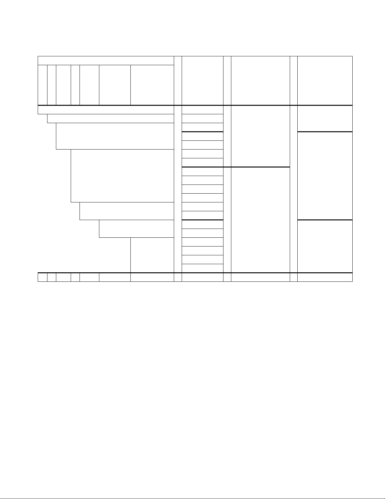
Table 1. VRN Model Selection.
Model Selection: Pressure Independent Control Valve
VRN PRESSURE INDEPENDENT CONTROL VALVES AND ACTUATORS
Valve
Fitting
Body/Flow Type
Size
Max flow rate
Trim
Actuator Adapter
Actuator Fail Position Accessories
VR - Pressure Independent Control Valve MVN613A0000*
N- Female NPT threaded MVN643A0000*
2- 2 way MVN713A0000*
MN6105A1011
(Leave blank)
= Fail in place
MN6105A1201
A - 1/2 (DN15)
B - 3/4 (DN20)
C - 1 (DN25)
D - 1-1/4 (DN32)
E - 1-1/2 (DN40)
F - 2 (DN50)
G - 2-1/2 (DN65)
H - 3 (DN80)
xxx.xx - Max flow rate designator
See Table 4.
P - Plated Brass
S - Stainless Steel
A - Standard Base
X - MN/MS DCA
Actuator Bracket
MN7505A2001
MN7505A2209
MS7505A2030
MS7505A2130
MS8105A1030
MS8105A1130
MS4105A1030
MS4105A1130
MS7103A2021*
MS7103A2221*
MS3103A1023*
MS3103A1223*
MS7503A2021*
FSO = Fail Safe Open
FSC = Fail Safe Closed
MS7503A2221*
VR N 2 A 001.00 P A + MVN613A0000 + + C1
Example part number: VRN2A001.00PA+MVN613A0000+C1
* Only compatible with valves 1-1/4” or smaller.
(Leave blank)
C1
- 1 meter cable
C3
- 3 meter cable
(Leave blank)
= No cable
= No
encolsure
3R - NEMA 3R Enclosure
(Leave blank)
= 3 ft cable
standard
3 38-00032—03
Page 4

VRN PRESSURE INDEPENDENT CONTROL VALVES AND ACTUATORS
Table 2. Actuator Control Description.
Actuator Control
MVN613A0000
MVN643A0000
MVN713A0000
Floating, Two-position (SPDT) (90 sec. timing), 24 V, Fail in Place
Floating, Two-position (SPDT or SPST) Fast Acting (30 sec. timing), 24 V, Fail in Place
0(2)-10 Vdc Modulating, 24 V, Fail in Place
MN6105A1011 Floating, Two-position (SPDT), 24 V, Fail in Place
MN6105A1201 Floating, Two-Position (SPDT), 24 V, Fail in Place with end switches
MN7505A2001 0(2)-10 Vdc Modulating, 24 V, Fail in Place
MN7505A2209 0(2)-10 Vdc Modulating, 24 V, Fail in Place with end switches
MS7505A2030 Universal, 0(2)-10 Vdc Modulating, Floating, Two-position (SPDT), 24 V, Fail Safe
MS7505A2130 Universal, 0(2)-10 Vdc Modulating, Floating, Two-Position (SPDT), 24 V, Fail Safe with end switches
MS8105A1030 Two-Position (SPST), 24 V, Fail Safe
MS8105A1130 Two-Position (SPST), 24 V, Fail Safe with end switches
MS4105A1030 Two-Position (SPST), 120 V, Fail Safe
MS4105A1130 Two-Position (SPST), 120 V, Fail Safe with end switches
MS7103A2021 2-10 Vdc Modulating, 24 V, Fail Safe
MS7103A2221 2-10 Vdc Modulating, 24 V, Fail Safe with end switches
MS3103A1023 Sylk-enabled, 24 V, Fail Safe
MS3103A1223 Sylk-enabled, 24 V, Fail Safe with end switches
MS7503A2021 Universal, 0(2)-10 Vdc Modulating, Floating, Two-Position, 24 V, Fail Safe
MS7503A2221 Universal, 0(2)-10 Vdc Modulating, Floating, Two-Position, 24 V, Fail Safe with end switches
38-00032—03 4
Page 5
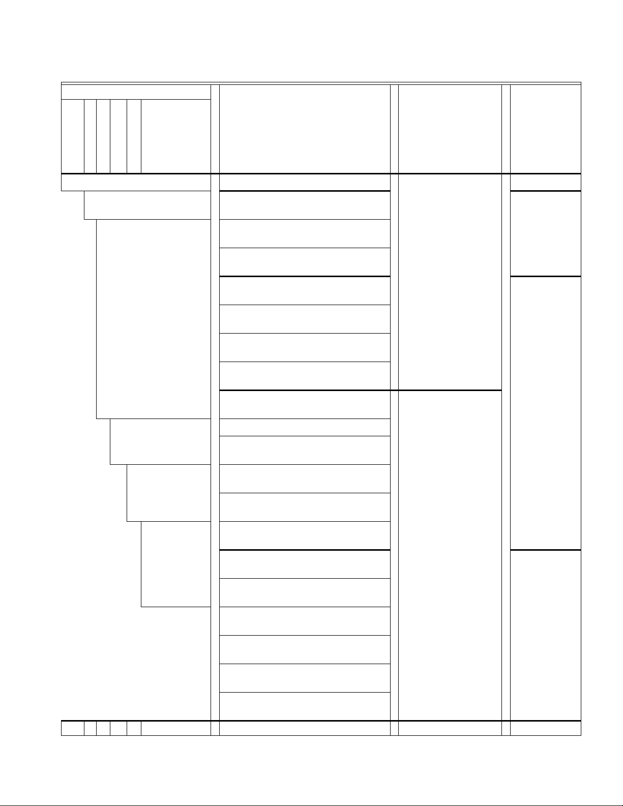
Table 3. Pressure Independent Valve Short Order Codes ½” – 3”.
Model Selection: Control Valve
VRN PRESSURE INDEPENDENT CONTROL VALVES AND ACTUATORS
Valve
Body Flow Type
Valve Size
Max Flow Rate
Trim
Adapter
Actuator
Actuator Fail Position Accessories
VRN - Pressure Independent Control Valve 0 - No Actuator (valve only)
2 - 2-way
A---1/2 (DN15)
B---3/4 (DN20)
C---1 (DN25)
D---1-1/4 (DN32)
E---1-1/2 (DN40)
F---2 (DN50)
G---2-1/2 (DN65)
H---3 (DN80)
1 - 24 Vac, Floating/2-Pos., 90 sec. (MVN613,
Fail in place)*
2 - 24 Vac, Floating/2-Pos., 30 sec. (MVN643,
Fail in place)*
3 - 24 Vac, Modulating 0(2)-10 Vdc (MVN713,
Fail in place)*
4 - 24 Vac, Floating/2-Position
(MN6105, Fail in place)
5 - 24 Vac, Mod. 0(2)-10 Vdc
(MN7505, Fail in place)
C - 24 Vac, Floating/2-Position w/ end switches
(MN 6105, Fail in place)
D - 24 Vac, Mod. 0(2)-10Vdc w/ end switches
(MN7505, Fail in place)
6 - 24 Vac, Mod. 0(2)-10 Vdc/Floating (MS7505,
Fail safe)
Flow Rate (GPM)
Options range from B-9.
See Table 4.
P - Nickel Chrome
Plated Brass
S - 316 Stainless Steel
7 - 24 Vac, 2-Position (MS8105, Fail safe)
8 - 100-250 Vac, 2-Position
(MS4105, Fail safe)
9 - 100-250 Vac, 2-Pos. w/ end switches
(MS4105, Fail safe)
A - 24 Vac, 2-Position w/ end switches
(MS8105, Fail safe)
B - 24 Vac, Mod 0(2)-10 Vdc/Floating w/ end
A - Standard Base
switches (MS7505, Fail safe)
E - 24Vac, Mod. 2-10 Vdc
X - MN/MS DCA
Actuator Bracket
(MS7103, Fail safe)*
F -24Vac, Mod. 2-10 Vdc w/ end switches
(MS7103, Fail safe)*
00 - None
00 - None
01 - 1 m Cable (C1)
03 - 3 m Cable (C3)
0 - No Actuator
or Fail in Place (FIP)
00 - None
02 - NEMA 3R
enclosure
1 - Fail Safe Open (FSO)
2 - Fail Safe Closed (FSC)
G - 24Vac, Sylk Enabled
(MS3103, Fail safe)*
H - 24Vac, Sylk Enabled w/ end switches
(MS3103, Fail safe)*
J - 24Vac, Universal 0(2)-10Vdc / Floating / 2-
Position (MS7503, Fail safe)*
K - 24Vac, Universal 0(2)-10Vdc / Floating / 2-
Position, w/ end switches (MS7503, Fail safe)*
VRN 2 A B P A 1 0 00
Example part number: VRN2ABPA1000
* Only compatible with valves 1-1/4” or smaller.
5 38-00032—03
01 - 3 ft Cable
Page 6

VRN PRESSURE INDEPENDENT CONTROL VALVES AND ACTUATORS
Table 4. VRN Flow Rate (GPM) and Differential Pressure with Short Order Code Indicator.
Model
Size
ΔP range
Min Max
Head
Loss
Short Order Code Indicator
(inch) (psi) (psi) (psi)BDEFGHJKLMNPQR S TU12345678 9
VRN2A 0.5
VRN2B 0.75
VRN2C 1
VRN2D 1.25
VRN2E 1.5
VRN2F 2
VRN2G 2.5
VRN2H 3
3 35 3 1234567
3 35 3 1234567
6356 8910*
3 35 3 1234567
6356 89
4 50 4 10 15 20
4 50 4 10 15 20
5505 2530
6.5586.5 35*
4 50 4 10 15 20
5505 2530
4584 35
6586 404550
7 58 7 55 60 65 70 75 80 85
11 58 11 95*
4 50 4 10 15 20
5505 2530
4584 35
6586 404550
7 58 7 55 60 65 70 75
4584 253035
6586 404550
7 58 7 55 60 65 70 75 80 85
11 58 11 95*
4584 253035
6586 404550
7 58 7 55 60 65 70 75 80 85
11 58 11 95*
* Valve does not have flow control insert.
Maximum GPM
38-00032—03 6
Page 7
VRN PRESSURE INDEPENDENT CONTROL VALVES AND ACTUATORS
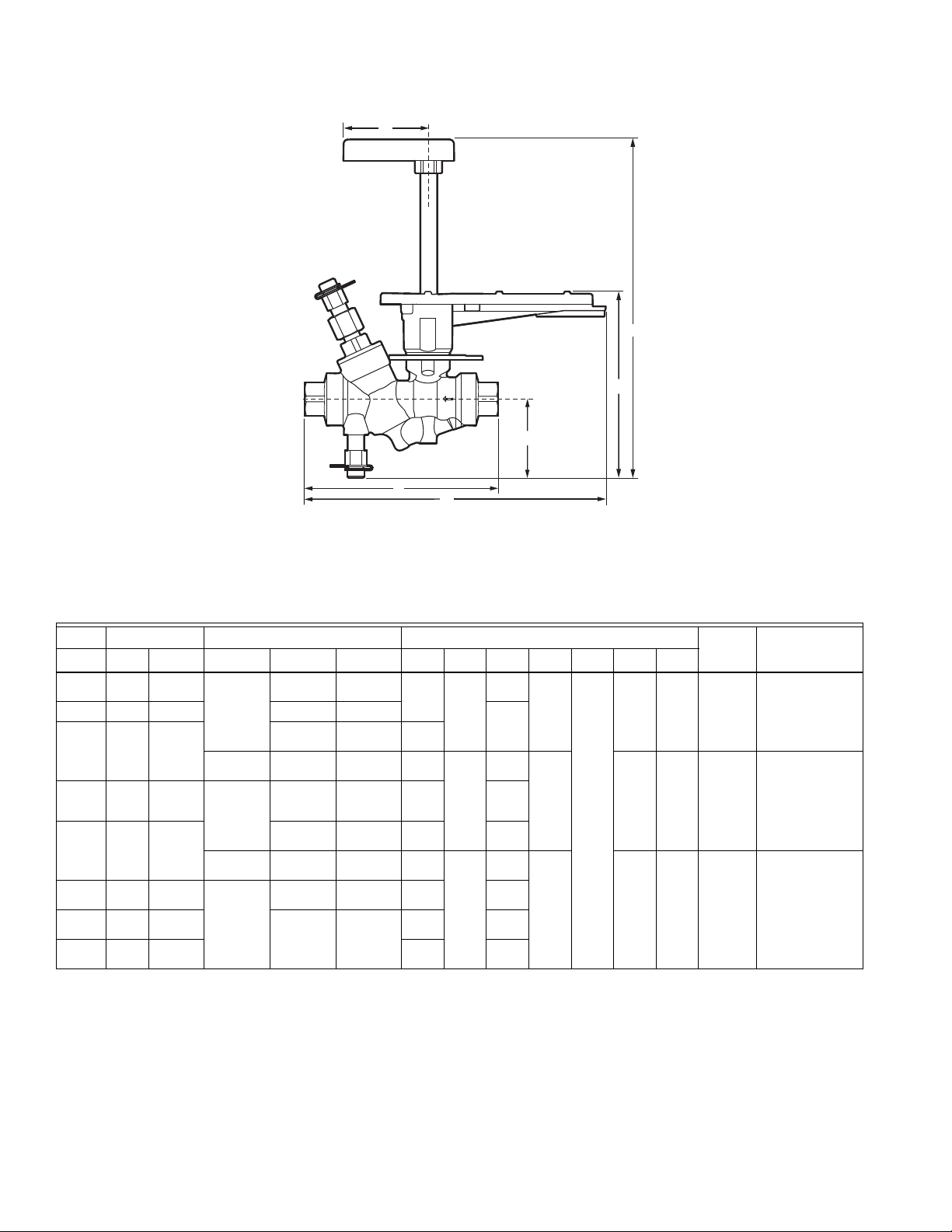
G
CLEARANCE ABOVE ACTUATOR 3/4 (19)
E
F
D
A
B
C
M34967
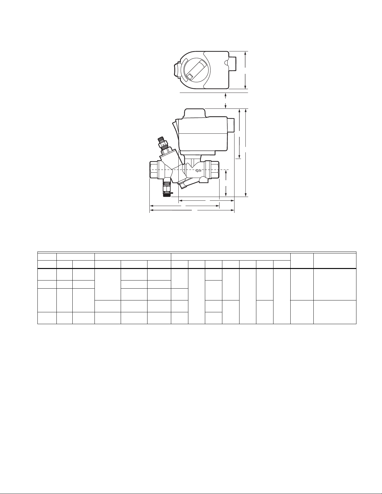
Fig. 1. Valve Dimensions with MVN Actuator; see Table 5.
Table 5. Valve Dimensions with MVN Actuator.
Model Pipe Size Flow, gpm (m3/h) Dimensions in in. (mm)
VRN2A 1/2 DN15 1.0 (0.23) 7.0 (1.6) 5.71
VRN2B 3/4 DN20 9.0 (2.0) 10 (2.3) 6.63
VRN2C 1 DN25 15.0 (3.4) 5.83
20 (4.5) 20 (4.5) 9.65
VRN2D 1–1/4 DN32 10 (2.3) 30 (6.8) 35 (7.9) 8.98
a
Do not use stainless steel replacement stem assemblies in valves with plated brass trim; galvanic reactions may occur.
(145)
(148)
(245)
(228)
4.56
(116)
6.57
(167)
(168)
9.13
(232)
8.79
(223)
2.32
(59)
2.41
(61)
3.87
(98)
7.36
2.8 (71) 2.5 (1.1) Stem: 5112-19
(187)
8.01
(203)
Weight
lb. (kg)
7.1 (3.2) Stem: 5112-20
Service Replacement
PartsNPT in. S.I. metric Min. Rating Max. Rating Full Port A B C D E F G
5112-22 (SS
Regulator:
8615-100 for 1-3 gpm;
8615-101 for 4-10 gpm
5112-23 (SS
Regulator:
8615-102
a
);
a
);
7 38-00032—03
Page 8
VRN PRESSURE INDEPENDENT CONTROL VALVES AND ACTUATORS
E
F
B
D
A
C
M35993
Fig. 2. Dimensions of valves used with MN/MS actuators; see Table 6.
Actuator not shown. See Figures 4 and 6 for MN/MS actuator dimensions.
Table 6. Dimensions of valves used with MN/MS actuators; see Fig. 2.
See Figures 4 and 6 for MN/MS actuator dimensions.
Model Pipe Size Flow, gpm (m3/h) Dimensionsc in in. (mm)
a
VRN2A
VRN2B
VRN2C
VRN2D
VRN2E
VRN2F
VRN2G
VRN2H
a
Long shaft supplied with “Zelix” direct coupled spring return actuators; short shaft supplied with MN series stay-in-place
1/2 DN15
3/4 DN20 9.0 (2.0) 10 (2.3)
1DN25
1–1/4 DN32
1–1/2 DN40
2DN50
2–1/2 DN65
3DN80
1.0 (0.23)
20 (4.5) 20 (4.5)
10 (2.3)
40 (9.1) 85 (19.3) 95 (21.6)
25 (5.7)
7.0 (1.6)
15.0 (3.4)
30 (6.8) 35 (7.9)
35 (7.9)
75 (17.0)
85 (19.3) 95 (21.6)
5.71
(145)
5.83
(148)
9.65
(245)
8.98
(228)
(213)
8.80
(224)
10.66
(271)
10.97
(279)
11.42
(290)
11.80
(300)
5.43
(138)
6.10
(155)
6.95
(177)
8.87
(225)
8.94
(227)
11.44
(291)
11.10
(282)
11.01
(280)
12.84
(326)
13.00
(330)
13.23
(336)
13.41
(341)
2.32
(59)
2.41
(61)
2.93
(74)
2.5 (64)
10.02
(255)
10.68
(271)
11.55
(293)
Fs
8.77
(223)
9.43
(240)
10.30
(262)
a
Weigh t
lb. (kg)
2.5 (1.1)
7.1 (3.2)
13.7 (6.2)
Service Replacement
PartsNPT in. S.I. metric Min. Rating Max. Rating Full Port A B C D E Fz
Stem: 5112-19
5112-22 (SS
Regulator :
8615-100 for 1-3 gpm;
8615-101 for 4-10 gpm
Stem: 5112-20
5112-23 (SS
Regulator :
8615-102
Stem: 5112-21
5112-24 (SS
Regulator :
8615-031
b
);
b
);
b
);
DCAs.
b
Do not use stainless steel replacement stem assemblies in valves with plated brass trim; galvanic reactions may occur.
c
Actuator dimensions fall within the envelope of the handle and mounting bracket. See actuator literature for detailed
dimensions.
38-00032—03 8
Page 9

VRN PRESSURE INDEPENDENT CONTROL VALVES AND ACTUATORS
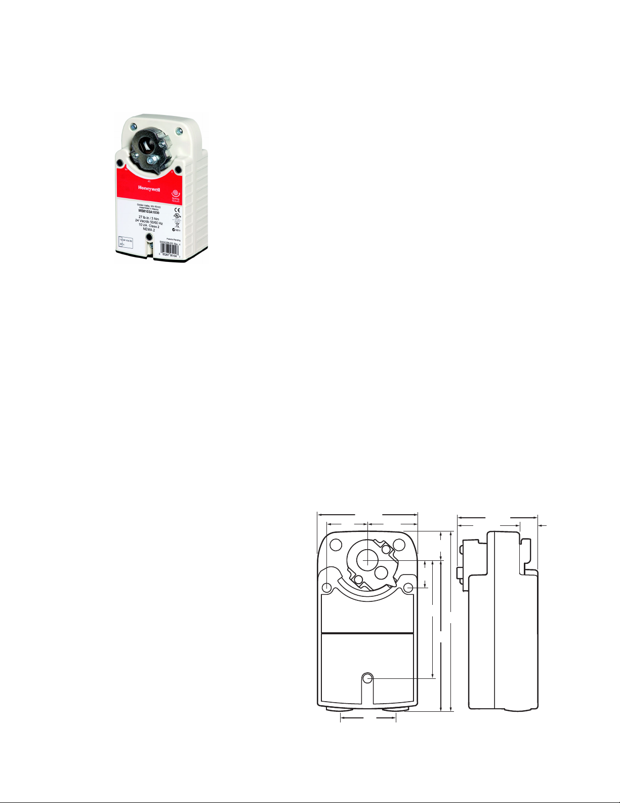
MVN Actuator
APPLICATION
MVN 3Nm (27 lb-in.) Control Valve Actuator is used with
the VRN2 Pressure Independent Control Valves to control
hot and chilled water with glycol solutions up to 50% in
heating, ventilating, and air conditioning (HVAC) systems
to provide two-position or modulating functions.
FEATURES
• Non-spring Return
• Floating and modulating
• Space saving, click-on installation – no tool required
• Extendable position indicator for easy commissioning
• Available with or without cable (1 m or 3 m length)
• Compatible with control ball valves from 1/2 to 1-1/4
inches.
• Actuator can be mounted on the valve in any of four
positions.
SPECIFICATIONS
Actuator Type: Valve
Rotational Stroke: 90° ±3°.
Fail Safe Mode: Non-spring return, Fail in place
Torque: 27 lb-in. (3 N m).
External Auxiliary Switches Available: No
Supply Voltage: 24 Vac +20%, -15%, 24 Vdc
Power Consumption: 5 VA- Modulating, 1.5 VA - Floating,
6 VA - Fast Acting SPDT
Environmental Rating: NEMA2
Frequency: 50 Hz; 60 Hz
Mounting: Click-on installation – no tool required
Noise Rating at 1m (Maximum): 35 dB(A) max at 1 m
[50 dB(A) for MVN643].
Materials: Plenum rated plastic housing
Operating Humidity Range (% RH):
5 to 95% RH, non-condensing
Ambient Temperature Range:
-4°F to 131°F (-20°C to 55°C)
Storage Temperature Range:
-40°F to 176°F (-40°C to 80°C)
Weight: 0.6 lb. (0.27 kg)
Dimensions: See Fig. 1 and Table 5.
Timing: 90 sec. (+/-10%) for MVN613 and MVN713;
30 sec. (+/-10%) for MVN643
Electrical Connections: Field wiring 18 to 20 AWG to
screw terminals, located under the removable access
cover.
G
CLEARANCE ABOVE ACTUATOR 3/4 (19)
E
B
MVN WITH 2-WAY BALL VALVE
Fig. 3. Dimensions; see Table 5 on page 7.
M34969
Humidity Ratings: 5% to 95% RH non-condensing.
Design Life (at Rated Voltage):
60,000 cycles; 1 cycle = 0°…90°…0°
Cable Specification:
18 AWG, Plenum Rated, 300 V, 10 A, 1 m or 3 m length
available.
Environmental Protection Ratings: IP40.
Approvals:
UL/cUL
UL60730
Table 7. Actuators and Accessories
Actuator Description Accessory
MVN613A0000 Floating control ball valve actuator
MVN643A0000 Fast acting SPDT contol ball valve actuator
MVN713A0000 Modulating control ball valve actuator
To order actuator with accessories order actuator part
number + accessory. For example: MVN613A0000 + C1
9 38-00032—03
C1- 1 meter cable
C3 - 3 meter cable
Page 10

VRN PRESSURE INDEPENDENT CONTROL VALVES AND ACTUATORS
Non-Spring Return Direct Coupled Actuator
APPLICATION
This non-spring return direct-coupled damper actuator
provides modulating and floating/2-position control for:
air dampers, air handlers, ventilation flaps, louvers, and
reliable control for air damper applications with up to
10 sq. ft./ 44lb.-in. (5 N m) and 20 sq. ft./88 lb.-in. (10 N m)
(seal-less damper blades; air friction-dependent).
FEATURES:
Maximum Noise Rating, Driving (dBA @ 1m): 35
Rotation to Open: By switch
Rotational Stroke Adjustment: Dual Integral Adj. Stops
(3 degree increments)
Compatible Damper Shafts:
1/4 to 1/2 in. square or 3/8 to 5/8 in. round
(6 to 13 mm square or 8 to 16 mm round)
Shaft Adapter Type: U-bolt clamp
Supply Voltage: 24 Vac +20%, -15%, 24 Vdc
Power Consumption: 5 VA
Materials: Plenum rated plastic housing
Ingress Protection Rating: IP54
Operating Humidity Range (% RH):
5 to 95% RH, non-condensing
Ambient Temperature Range:
-5°F to +140°F (-20°C to +60° C)
Storage Temperature Range:
-22°F to +176°F (-30°C to +80°C)
Weight: 1 lb (0.45 kg)
Includes: Mounting bracket, screws, shaft adapter,
water-tight strain-relief cable fittings
Comments: Integral 1/2 in. NPSM conduit connection.
• Declutch for manual adjustment
• Adjustable mechanical end limits
• Access cover includes enclosed screw terminal strip
(22 to 14 AWG) for electrical connections
• Models available with 3 foot 18 AWG color-coded
cable
• Mountable in any orientation
• Function selection switch for selecting modulating or
floating/2-position control
SPECIFICATIONS
Actuator Type: Damper; Valve
Rotational Stroke: 95° ±3 degrees
Fail Safe Mode: Non-spring return
Tor que : 44 lb-in. (5 N m)
External Auxiliary Switches Available: No
Environmental Rating: NEMA2
Frequency: 50 Hz; 60 Hz
Manual operation: Declutch mechanism
Mounting: Direct coupled
Approvals:
CE: 89/336/ECC, 73/23/EEC
C-Tick: N314
Underwriters Laboratories, Inc.: UL873, Plenum Rated
Canadian Underwriters Laboratories, Inc.:
cUL C22.2 No. 24-93
1-5/8
(41)
3-11/32
(85)
5-9/32
(134)
2-7/16
(62)
2-19/32
(66)
Fig. 4. Non-spring return direct coupled actuator
dimensions in inches (mm).
M23103A
4-1/4
(108)
38-00032—03 10
Page 11

VRN PRESSURE INDEPENDENT CONTROL VALVES AND ACTUATORS
M37351
2-7/8 (73)
6-1/2
(165)
5-3/8
(137)
3-1/8 (79)
3-1/8 (79)
7
(178)
3-17/64 (83)
1-9/16
(40)
FOR 1/2 INCH SHAFT.
Spring Return 3 Nm Diamond
APPLICATION
MS7103 and MS3103 Spring Return Direct Coupled
Actuators (DCA) are used within heating, ventilating and
air-conditioning (HVAC) systems. They can drive a variety
of quarter-turn, final control elements requiring spring
return fail-safe operation.
FEATURES
• Brushless DC submotor with electronic stall
protection
• Self-centering shaft adaptor (shaft coupling) for wide
range of shaft sizes
•Fast test mode
• MS7103 models for use with 2-10 Vdc control
• MS3103 models for use with Sylk-enabled controllers
• Models available with two internal end switches
• Durable plastic housing with built-in mechanical end
limits
• Spring return direction field selectable
• Shaft position indicator and scale
• UL (cUL) listed and CE compliant
• Plenum rated actuator and control/power cable
Cable Specification:
Power Cable: Plenum Rated, 3 ft (0.914 m) length from end
of access cover, 18 AWG
Switch Cable: Appliance Rated, 3 ft (0.914 m) length from
end of access cover, 18 AWG
Ingress Protection Rating: IP54
Environmental Rating: NEMA 2
Frequency: 50 Hz; 60 Hz
Mounting: Direct Coupled
Maximum Noise Rating, Driving (dBA @ 1m): < 40
Maximum Noise Rating, Spring Return (dBA @ 1m): < 65
Rotational Stroke Adjustment: Mechanically limited
7.5 degree increments
Compatible Damper Shafts: 3/8 to 3/4 in. round or 1/4 to
1/2 in. square (9 to 19 mm round or 6 to 13 mm square)
Shaft Adapter Type: U-bolt
Materials: Plenum rated plastic housing
Operating Humidity Range (% RH): 5 to 95% RH, non-
condensing
Ambient Operating Temperature: -40 F to +150F (-40 C
to +65 C)
Shipping and Storage Temperature: -40 F to +150F (-40 C
to +65 C)
Weight: 1.7 lb (0.78 kg)
Approvals
UL60730
IEC 60730-1 and Part 2–4
UL1097 for Double Insulation
CE Certification Low Voltage Directive 2014/35/EU
CE EMC 2004/108/EC
Switch cables are UL certified only
SPECIFICATIONS
Actuator Type: Damper; Valve
Rotational Stroke: 95 ±3 degrees
Fail Safe Mode: Spring Return
Tor que : 27 lb-in. (3 Nm)
Spring Return Torque: 27 lb-in (3 Nm)
Spring Return Direction: By orientation
External Auxiliary Switches Available: No
Fig. 5. Dimensions in in. (mm).
11 38-00032—03
Page 12
VRN PRESSURE INDEPENDENT CONTROL VALVES AND ACTUATORS
M27712A
3-55/64 (98)
6-61/64
(177)
1-1/8
(29)
5-27/32
(148)
1-9/16
(40)
3-5/32 (80)
4-9/16
(116)
1-15/16
(49)
1-1/16
(27)
2-1/64
(55)
47/64
(19)
2-27/64 (61)
Spring Return Direct Coupled Actuator
APPLICATION
MS4105, MS7405, MS7505, and MS8105 Spring Return
Direct Coupled Actuators (DCA) are used within heating,
ventilating, and air-conditioning (HVAC) systems. They can
drive a variety of quarter-turn, final control elements
requiring spring return fail-safe operation.
FEATURES
• Brushless DC submotor with electronic stall
protection on all models
• Self-centering shaft adaptor (shaft coupling) for wide
range of shaft sizes
• Access cover includes enclosed screw terminal strip
(22 to 14 AWG) for electrical connections.
• Models available with 3 foot 18 AWG color-coded
cable
• Durable plastic housing with built-in mechanical end
limits
• Spring return direction field selectable
• Shaft position indicator and scale
• UL (cUL) listed and CE compliant
• All models are plenum rated per UL873
SPECIFICATIONS
Actuator Type: Damper; Valve
Frequency: 50 Hz; 60 Hz
Mounting: Direct Coupled
Maximum Noise Rating, Holding (dBA @ 1m):
20 (no audible noise)
Maximum Noise Rating, Driving (dBA @ 1m): 50
Rotation to Open: By switch
Rotational Stroke Adjustment:
Mechanically limited 5 degree increments
Compatible Damper Shafts:
1/4 to 1/2 in. square or 3/8 to 5/8 in. round
(6 to 13 mm square or 9 to 16 mm round)
Shaft Adapter Type: Self-centering clamping
Materials: Plenum rated plastic housing
Supply Voltage: 24 Vac +20%, -15%, 24 Vdc
Power Consumption: 5 VA
Operating Humidity Range (% RH):
5 to 95% RH, non-condensing
Ambient Temperature Range: -40°F to +149°F
(-40°C to +65°C) for two-position actuators only
Storage Temperature Range:
-40°F to +150°F (-40°C to +65°C)
Weight: 3.5 lb. (1.6 kg)
Includes: Mounting bracket, self-centering shaft adapter
Approvals:
CE: EMC 2004/108/EC; Certification Low Voltage
Directive 2006/95/EC; IEC 60730-1 and Part 2-14
C-Tick: N314
Underwriters Laboratories, Inc.: UL873
Canadian Underwriters Laboratories, Inc.:
cUL C22.2 No. 24-93
Rotational Stroke: 95 ±3 degrees
Fail Safe Mode: Spring Return
Torque: 44 lb-in. (5 N m)
Spring Return Torque: 44 lb-in. (5 N m)
Spring Return Direction: By orientation
External Auxiliary Switches Available: No
Environmental Rating: NEMA2
38-00032—03 12
Fig. 6. Spring return direct coupled actuator
dimensions in inches (mm).
Page 13

VRN PRESSURE INDEPENDENT CONTROL VALVES AND ACTUATORS
Table 8. Actuator Accessories and Replacement Parts.
MVN613A0000
MVN643A0000
MVN713A0000
Couple Actuators
MN Non-Fail-
Safe Direct
Part Number Description
5112-3R Weather Enclosure Assembly x x
MVNAAA Replacement Valve Adaptor x x x
MVNAAL Replacement Valve Adaptor, Low Profile
Direct Couple
MS Fail-Safe
Actuators
MVNAC7131 Replacement Cable with Terminal 1m, Modulation
x
(RED, BLACK, WHITE)
MVNAC6131 Replacement Cable with Terminal 1m, Floating
xx
(RED, BLACK, WHITE)
MVNAT3 Replacement Screw type Terminal Block, Pluggable x x x
5112-11 Replacement actuator bracket x x
205860 Minimum position Potentiometer x x
32006306-001 Resistor Kit (500 ohm); converts 4-20 mA signal to 2-10 Vdc x x
Q7002B1009 Universal Interface Module x x
STRN-SCSA Self-centering Shaft Adapter x
32000085-001 Strain Relief Fitting (10 pack) x
STRN-STRNRLF Stain Relief Fitting (10 pack) x
13 38-00032—03
Page 14

VRN PRESSURE INDEPENDENT CONTROL VALVES AND ACTUATORS
Application Notes
IMPORTANT
Valve sizing is important for correct system
operation. Undersized valves do not have sufficient
capacity at maximum load. Oversized valves do not
have sufficient authority over the load in
modulating applications.
Oversized valves can cause excessive cycling and
the seat and ball can be damaged because of the
restricted opening.
Proper Use
VRN valves are intended for use in chilled water and hot
water closed loop applications only, with a temperature
range of 35 to 250 °F, and pressures up to 360 psig.
Water should be properly filtered, treated and conditioned
for good operating performance, and according to
recommendations of the boiler or chiller manufacturers.
The installation of strainers and filters is recommended.
Do not use with manual balancing valves.
IMPORTANT
The presence of excessive iron oxide (red rust) in
the system voids the valve warranty.
Effective Flow Rate
The built-in differential pressure regulator makes fluid flow
through the valve independent of changes in supply
pressure, eliminating “hunting” by the control system, even
at low coil flow. The pressure regulator virtually eliminates
cavitation in the valve, and decouples the control valve
from the effects of piping components such as reducers
and elbows.
Pressure independent control valves are sized to match
design coil flow regardless of coil size. VRN2 valves
eliminate the need to balance the system for proper flow,
and allow chillers to be operated at design temperature
differential for maximum efficiency at every load condition.
When used in a system with variable speed pump drives,
3-way valves and coil bypass lines are not required. In new
construction, VRN2 valves perform better than reverse
return piping designs without the extra materials these
systems need. Pressure-independent control requires less
flow, enabling use of smaller piping, pumps, and chillers.
Flow Characteristics
The VRN2 two-way dynamic pressure-regulating control
valves have:
• an equal percentage flow characteristic with
characterized flow control insert.
Required Operating Torque
Both Honeywell non-spring return MVN and spring return
low torque direct coupled actuators can be utilized with the
VRN2 valves. VR valves use a patented seat design that
reduces the torque needed from the actuator.
Table 9. Close-off, Differential Pressure Ratings.
Close-off
Pressure Rating
Valve Type Valve Size
2 way 1/2 in., 3/4 in. 100
1 in., 1-1/4 in., 1-1/2 in. 100
(psi)
TYPICAL SPECIFICATIONS
Valve Actuator
Actuator shall accept analog modulating [(0)2-10 Vdc],
floating (tri-state), or two-position signal as indicated in
the control sequence. Actuators shall be manufactured by
Honeywell. Actuator shall provide minimum torque
required for full valve shutoff position. Wiring terminals
shall be provided for installation to control signal and
power wiring.
Actuator shall be available with housing suitable for
outdoor installation.
Accessories Identification tags shall be available for all
valves.
Pressure Independent Valve
Valve housing shall consist of forged brass rated at no less
than 360 psi at 250°F. Standard valve ball shall consist of
chemically nickel-plated brass. Manufacturer shall be able
to provide optional 316 stainless steel ball and stem. The
valve shall have an integral differential pressure regulator
to maintain constant pressure drop across valve seat to
decouple valve flow from system pressure changes. Flow
control accuracy shall be +/-5% or better. Regulator will be
constructed from 316 stainless steel with a rolling
diaphragm and operate under positive pressure. Regulator
shall be located above axis of pipe with ¼” ISO test port
fittings to allow pressure measurement and venting.
Valve stem assembly shall be of a pack-less design and be
field-replaceable without removing the valve body from the
piping. Teflon™ seals shall hold the stem in alignment, and
protect the O-ring from system temperature fluctuations.
Stem O-ring shall be made of peroxide-cured EPDM and
be isolated from system treatment chemicals by a reservoir
of silicon grease. Valve shall have a blow-out proof stem
with minimum 600 psi rating.
38-00032—03 14
Page 15

VRN PRESSURE INDEPENDENT CONTROL VALVES AND ACTUATORS
CAUTION
M34979
FLOW FLOW
2-WAY; CLOSED
2-WAY; OPEN
NOTES: FOR 2-WAY VALVES TO MOUNT ACTUATOR ON OPEN VALVE, TURN ACTUATOR
FULLY COUNTER CLOCKWISE AS SHOWN. FOR 2-WAY VALVES TO MOUNT
ACTUATOR ON CLOSED VALVE, TURN ACTUATOR FULLY CLOCKWISE AS SHOWN.
45
45
M33091
INSTALLATION
When installing this product...
1. Read these instructions carefully. Failure to follow
them could damage the product or cause a
hazardous condition.
2. Check ratings given in instructions and on the
product to ensure the product is suitable for your
application.
3. Installer must be a trained, experienced service
technician.
4. After installation is complete, check out product
operation as provided in these instructions.
Preparation
Equipment Damage Hazard
Foreign particles like dirt and metal chips can
damage the ball seals.
For trouble-free operation of the product, good
installation practice must include initial system
flushing, and chemical water treatment. Clean the
lines upstream of particles larger than 1/16 inch
diameter (welding slag, pipe scale, sand and other
suspended particulate). Use of a 50 micron (or
finer) system side stream filter is suggested.
Remove all filters before flushing.
3. Eliminate air from system.
4. Two-way valves are marked to show flow direction.
IMPORTANT
Flow arrows must point in the direction of the flow
for proper operation.
5. Stem rotation:
a. For two-way valves:
(1) Clockwise to close.
(2) Counterclockwise to open.
NOTE: After valves have been installed in the piping,
the installer can determine the ball
orientation within the valve from the notches
in the top of the valve stem. For two-way
valves, the lengthwise direction of the notch
indicates the flow through the ball (i.e. when
the notch is parallel to the axis of the valve
between A and B ports, the ball will allow flow
through the valve).
6. Valve must be mounted with the actuator/bracket
above the valve body. Do not install the valve with the
stem below horizontal or upside down.
(See Fig. 8 – 10.)
Do not use boiler additives, solder flux and wetted
materials which are petroleum based or contain
mineral oil, hydrocarbons, or ethylene glycol
acetate. Compounds which can be used, with
minimum 50% water dilution, are diethylene glycol,
ethylene glycol, and propylene glycol (antifreeze
solutions).
If installing these valves in an addition to, or
retrofitting an existing building, do not assume that
the fluid in the existing piping meets these criteria.
Mechanical Installation
IMPORTANT:
Hold valve with pipe wrench by hexagonal fitting
ONLY. Do NOT handle the valve body with the pipe
wrench; product damage may result.
The valves are tapped in NPT and should be sealed with an
approved pipe sealant. Torque should not exceed 75 lb-ft.
Refer to actuator literature for actuator dimensions.
1. Clean the lines upstream of particles larger than
1/16 in. diameter (welding slag, pipe scale and other
contaminants).
2. Proceed with installation once the system specifics
(expansion/contraction of the system and its
medium as well as operating pressures) are within
tolerances.
Fig. 7. Orientation of valve.
Fig. 8. Acceptable valve angle from vertical
for MVN actuators.
15 38-00032—03
Page 16

VRN PRESSURE INDEPENDENT CONTROL VALVES AND ACTUATORS
85 85
M29519A
M29526B
VALVE BODY
VALVE STEM
COUPLER**
WING NUT**
MOUNTING
PLATE**
STEM ASSEMBLY COVER**
SCREWS (2)**
HANDLE (REMOVABLE) FOR
MANUALLY ROTATING SHAFT**
STEM ASSEMBLY**
SCREWS (2)**
STEM RETAINER PLATE
BOLT**
ANTI-ROTATION
BRACKET**
**
INCLUDED IN REPLACEMENT KIT (PART NO. 5112-11).
Fig. 9. Acceptable valve angle from vertical
for MN and MS actuators.
Fig. 10. Vertical valve installation.
M34954
Fig. 11. Actuator mounting plate adjustment.
Mounting Plate Adjustment
NOTE: See Fig. 11 for valve exploded view.
The Actuator Mounting Plate can be rotated to a different
position for installation in confined spaces. This is
accomplished as follows:
1. Remove the handle from the shaft and set it aside.
2. Remove the two screws that hold the stem assembly
to the mounting plate and set them aside.
3. Remove and set aside the stem assembly.
4. Remove and set aside the two screws that attach the
mounting plate to the valve.
5. Remove and set aside hold-down ring from mounting
plate.
6. Rotate mounting plate around valve top to the
desired position.
NOTE: Take note of the screw hole positions on the valve.
They limit the mounting plate positions.
7. Lower ring down to valve body and engage it in the
new position relative to the mounting plate.
8. Tighten screws to valve body securing the mounting
plate.
9. Reattach the stem assembly to the mounting plate.
10. If desired, replace the handle on the shaft.
38-00032—03 16
Page 17

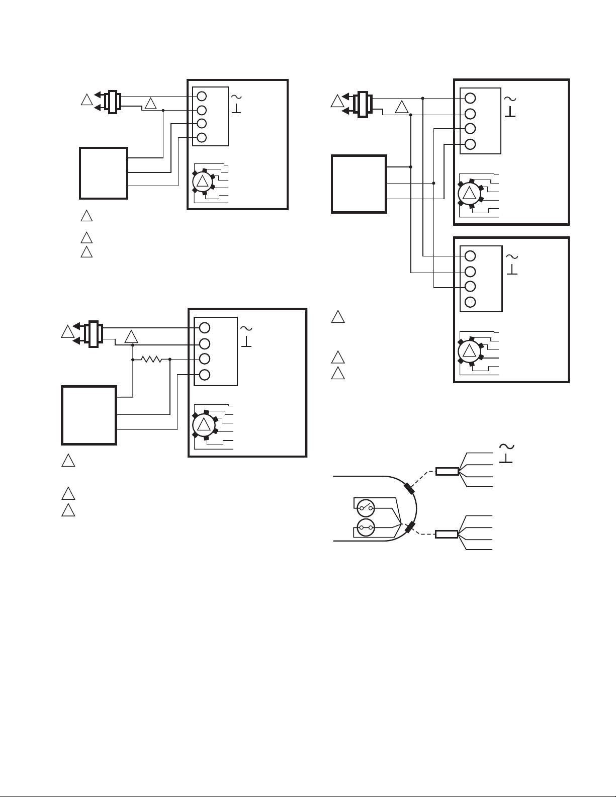
Electrical Installation
432
FLOATING ACTUATOR
24 VAC
1
1
POWER SUPPLY. PROVIDE DISCONNECT MEANS AND OVERLOAD
PROTECTION AS REQUIRED.
CONNECTION REQUIRED FOR SPST CONTROL.
2
CONTROLLER
2
DIRECT
REVERSE
SERVICE/OFF
M34869A
3
4
3
2
FLOATING ACTUATOR
24 VAC
Direct
Reverse
Service/Off
1
1
POWER SUPPLY. PROVIDE DISCONNECT MEANS
AND OVERLOAD PROTECTION AS REQUIRED.
FLOATING
CONTROLLER
M18946A
24 VAC
1
1
POWER SUPPLY. PROVIDE DISCONNECT MEANS
AND OVERLOAD PROTECTION AS REQUIRED.
PROPORTIONAL
CONTROLLER
+
–
FEEDBACK
1
325
PROPORTIONAL ACTUATOR
FEEDBACK
+
0(2)-10 VDC OF 0(4)-20 mA CONTROL SIGNAL ACCEPTABLE.
SET CONTROL SIGNAL DIP SWITCH TO “OFF” FOR VOLTAGE.
SET TO “ON” FOR CURRENT.
2
2
2 -10 Vdc
2 -10 Vdc
0 -10 Vdc
0 -10 Vdc
M18947B
4
5°
85°
S1 S2
S3 S5 S6
M25214A
END SWITCHES (CLASS II-ONLY)
FLOATING ACTUATOR
24 VAC
1
POWER SUPPLY. PROVIDE DISCONNECT MEANS AND OVERLOAD
PROTECTION AS REQUIRED.
FLOATING
CONTROLLER
M33137D
2
3
4
1
BLACK
WHITE
BROWN
2
1. If necessary, remove actuator wiring cover.
2. Wire actuator using Figures 12 through 35 for the
application required.
3. Replace cover.
Wiring
VRN PRESSURE INDEPENDENT CONTROL VALVES AND ACTUATORS
Fig. 12. MN6105 with On/Off SPDT Control.
Fig. 13. MN6105 with Floating Control.
Fig. 14. MN7505 with 0(2)-10 Vdc Control.
Fig. 15. Wiring for MN6105 and MN7505 models with
aux./end switches.
Fig. 16. MVN613 with Floating Control.
17 38-00032—03
Page 18

VRN PRESSURE INDEPENDENT CONTROL VALVES AND ACTUATORS
POWER SUPPLY. PROVIDE DISCONNECT MEANS AND OVERLOAD
PROTECTION AS REQUIRED.
FLOATING ACTUATOR
24 VAC
1
FLOATING
CONTROLLER
2
3
4
1
M33138C
BLACK
WHITE
BROWN
2
M33557C
FLOATING ACTUATOR
1
POWER SUPPLY. PROVIDE DISCONNECT MEANS AND OVERLOAD
PROTECTION AS REQUIRED.
2
3
4
1
24 VAC
BLACK
BROWN
WHITE
SPST
PROPORTIONAL ACTUATOR
1
POWER SUPPLY. PROVIDE DISCONNECT MEANS AND OVERLOAD
PROTECTION AS REQUIRED.
4-20mA
CONTROLLER
M33141C
1
2
3
+
+
–
DIP SWITCH POSITION
1 2 MODE
OFF OFF 2-10V
OFF ON 0-10V
ON OFF 10-2V
ON ON 10-0V
PROPORTIONAL/MODULATING: 4-20mA CONTROLLER OUTPUT WITH
500Ω SERIES RESISTOR
TO OTHER
ACTUATORS
500 OHMS,
1/2 W
MINIMUM
24 VAC
RED
BLACK
WHITE
1
PROPORTIONAL ACTUATOR
24 VAC
1
POWER SUPPLY. PROVIDE DISCONNECT MEANS AND OVERLOAD
PROTECTION AS REQUIRED.
24 VDC SUPPLY ACCEPTABLE.
0 (2)-10 VDC
CONTROLLER
M33140A
1
2
3
+
+
–
DIP SWITCH POSITION
1 2 MODE
OFF OFF 2-10V
OFF ON 0-10V
ON OFF 10-2V
ON ON 10-0V
PROPORTIONAL/MODULATING: 0(2)...10 VDC OR 10...0(2) VDC CONTROLLER OUTPUT
2
RED
BLACK
WHITE
2
1
SPDT
24 VAC
1
1
2
LINE VOLTAGE POWER SUPPLY.
PROVIDE DISCONNECT MEANS AND
OVERLOAD PROTECTION AS REQUIRED.
SET SWITCH TO FLOATING.
ACTUATOR
V
0°-90°/MODULATING
90°-0°/FEEDBACK
2-10 VDC
10-2 VDC
0-10 VDC
10-0 VDC
FLOATING, FWD
FLOATING, REV
2
RED
BLACK
BROWN
WHITE
CLASS 2
24 VAC
1
1
2
LINE VOLTAGE POWER SUPPLY.
PROVIDE DISCONNECT MEANS AND
OVERLOAD PROTECTION AS REQUIRED.
SET SWITCH TO FLOATING.
ACTUATOR
V
4
3
1
2
2-10 VDC
10-2 VDC
0-10 VDC
10-0 VDC
FLOATING, FWD
FLOATING, REV
2
0°-90°/MODULATING
90°-0°/FEEDBACK
RED
BLACK
BROWN
WHITE
CLASS 2
Fig. 17. MVN613 or MVN643 with Two Position SPDT
Control.
Fig. 18. MVN643 with Two Position SPST Control.
Fig. 20. MVN713 with 0(2)-10 Vdc Control.
Fig. 21. MS7505 with Two Position SPDT Control.
38-00032—03 18
Fig. 19. MVN713 with 4-20mA Control.
Fig. 22. MS7505 with Floating Control.
Page 19
VRN PRESSURE INDEPENDENT CONTROL VALVES AND ACTUATORS
ACTUATOR
4 TO 20 mA
PROPORTIONING
CONTROLLER
24 VAC
1
1
2
3
2
490 TO 510
OHMS,
1/2 W
MINIMUM
LINE VOLTAGE POWER SUPPLY.
PROVIDE DISCONNECT MEANS AND
OVERLOAD PROTECTION AS REQUIRED.
24 VDC SUPPLY ACCEPTABLE.
SET SWITCH TO MODULATING IF AVAILABLE.
V
–
+
FEEDBACK
4
3
1
2
M37321
2-10 VDC
10-2 VDC
0-10 VDC
10-0 VDC
FLOATING, FWD
FLOATING, REV
3
0°-90°/MODULATING
90°-0°/FEEDBACK
RED
BLACK
BROWN
WHITE
CLASS 2
ACTUATOR
0/2 TO 10 VDC
PROPORTIONING
CONTROLLER
24 VAC
1
1
2
3
2
LINE VOLTAGE POWER SUPPLY.
PROVIDE DISCONNECT MEANS
AND OVERLOAD PROTECTION
AS REQUIRED.
24 VDC SUPPLY ACCEPTABLE.
SET SWITCH TO MODULATING
IF AVAILABLE.
V
–
+
FEEDBACK
4
3
1
2
M37322
2-10 VDC
10-2 VDC
0-10 VDC
10-0 VDC
FLOATING
, FWD
FLOATING
, REV
3
ACTUATOR
V
4
3
1
2
2-10 VDC
10-2 VDC
0-10 VDC
10-0 VDC
FLOATING
, FWD
FLOATING
, REV
3
0°-90°/MODULATING
90°-0°/FEEDBACK
RED
BLACK
BROWN
WHITE
0°-90°/MODULATING
90°-0°/FEEDBACK
RED
BLACK
BROWN
WHITE
CLASS 2
ACTUATOR
SPST SWITCHES
MAIN
CABLE
M37303A
RED
BLACK
WHITE
BROWN
SWITCHES
CABLE
BLUE
BROWN
GRAY
BLACK
FEEDBACK OR 90˚−0˚
+ OR 0˚−90˚
CLASS 2
RED
1
0/2 TO 10 VDC
PROPORTIONING
CONTROLLER
FEEDBACK
1
2
3
24 VAC
2
–
+
LINE VOLTAGE POWER SUPPLY. PROVIDE DISCONNECT MEANS
AND OVERLOAD PROTECTION AS REQUIRED.
24 VDC SUPPLY ACCEPTABLE.
SET SWITCH TO MODULATING IF AVAILABLE.
1
2
3
4
3
BLACK
WHITE
BROWN
ACTUATOR
V
0°-90°/MODULATING
90°-0°/FEEDBACK
2-10 VDC
10-2 VDC
0-10 VDC
10-0 VDC
FLOATING
, FWD
FLOATING
, REV
M37320
Fig. 23. MS7103 with 2-10 Vdc Control (MS7503 shown,
ignore selection switch).
Fig. 24. MS7103 with 4-20 mA Control (MS7503 shown,
ignore selection switch).
Fig. 25. MS7103 with 2-10 Vdc Control using two
actuators (MS7503 shown, ignore selection switch).
Fig. 26. Wiring for MS7103 and MS3103 Auxiliary
Switches. Gray/Black = Normally Open. Closed in range
80 degrees to Fully Open. Blue/Brown = Normally
Closed. Open in range 10 degrees to Fully Open.
19 38-00032—03
Page 20

VRN PRESSURE INDEPENDENT CONTROL VALVES AND ACTUATORS
ACTUATOR
SPST
24 VAC
1
1
2
2
LINE VOLTAGE POWER SUPPLY. PROVIDE DISCONNECT MEANS
AND OVERLOAD PROTECTION AS REQUIRED.
24 VDC SUPPLY ACCEPTABLE.
V
1
2
M34973
3
ACTUATOR
SPST
1
1 LINE VOLTAGE POWER SUPPLY. PROVIDE DISCONNECT MEANS
AND OVERLOAD PROTECTION AS REQUIRED.
V
1
2
M34974
2
ACTUATOR
0/2 TO 10 VDC
PROPORTIONING
CONTROLLER
24 VAC
1
1
2
3
2
LINE VOLTAGE POWER SUPPLY.
PROVIDE DISCONNECT MEANS AND
OVERLOAD PROTECTION AS REQUIRED.
24 VDC SUPPLY ACCEPTABLE.
SET SWITCH TO MODULATING.
V
OR +
OR N/A
FEEDBACK
–
+
FEEDBACK
5
4
3
1
2
M19576A
2-10 VDC
10-2 VDC
0-10 VDC
10-0 VDC
Fltg, fwd
Fltg, rev
3
SPDT
ACTUATOR
0/2 TO 10 VDC
PROPORTIONING
CONTROLLER
24 VAC
1
1
2
3
2
LINE VOLTAGE POWER SUPPLY.
PROVIDE DISCONNECT MEANS AND
OVERLOAD PROTECTION AS REQUIRED.
24 VDC SUPPLY ACCEPTABLE.
SET SWITCH TO MODULATING.
V
OR +
OR N/A
FEEDBACK
–
+
FEEDBACK
5
4
3
1
2
M19577A
2-10 VDC
10-2 VDC
0-10 VDC
10-0 VDC
Fltg, fwd
Fltg, rev
3
SPST
ACTUATOR
0/2 TO 10 VDC
PROPORTIONING
CONTROLLER
24 VAC
1
1
2
3
2
LINE VOLTAGE POWER SUPPLY. PROVIDE DISCONNECT MEANS
AND OVERLOAD PROTECTION AS REQUIRED.
24 VDC SUPPLY ACCEPTABLE.
SET SWITCH TO MODULATING.
V
OR +
OR N/A
FEEDBACK
–
+
FEEDBACK
5
4
3
1
2
M34976
2-10 VDC
10-2 VDC
0-10 VDC
10-0 VDC
Fltg, fwd
Fltg, rev
3
ACTUATOR
4 TO 20 mA
PROPORTIONING
CONTROLLER
24 VAC
1
1
2
3
2
490 TO 510
OHMS,
1/2 W
MINIMUM
LINE VOLTAGE POWER SUPPLY.
PROVIDE DISCONNECT MEANS AND
OVERLOAD PROTECTION AS REQUIRED.
24 VDC SUPPLY ACCEPTABLE.
SET SWITCH TO MODULATING.
V
OR +
OR N/A
FEEDBACK
–
+
FEEDBACK
5
4
3
1
2
M34977
2-10 VDC
10-2 VDC
0-10 VDC
10-0 VDC
Fltg, fwd
Fltg, rev
3
Fig. 30. MS7505 with override to full closed.
Fig. 27. MS8105 with Two Position SPDT Control.
1
1
2
3
24 VAC
2
LINE VOLTAGE POWER SUPPLY.
PROVIDE DISCONNECT MEANS AND
OVERLOAD PROTECTION AS REQUIRED.
24 VDC SUPPLY ACCEPTABLE.
SET SWITCH TO FLOATING.
Fig. 28. MS7505 with Floating Control.
38-00032—03 20
Fig. 29. MS7505 with override to full open.
1
2
3
4
5
3
ACTUATOR
V
OR +
OR N/A
FEEDBACK
2-10 VDC
10-2 VDC
0-10 VDC
10-0 VDC
Fltg, fwd
Fltg, rev
M34975
Fig. 31. MS7505 with 0(2)-10 Vdc Controllers.
Fig. 32. MS7505 with 4-20mA Controllers.
Page 21

VRN PRESSURE INDEPENDENT CONTROL VALVES AND ACTUATORS
S1S3
S2
M35813
ACTUATOR
0/2 TO 10 VDC
PROPORTIONING
CONTROLLER
1
2
3
2
LINE VOLTAGE POWER SUPPLY.
PROVIDE DISCONNECT MEANS AND
OVERLOAD PROTECTION AS REQUIRED.
24 VDC SUPPLY ACCEPTABLE.
SET SWITCH TO MODULATING.
V
OR +
OR N/A
FEEDBACK
5
4
3
1
2
M34978
2-10 VDC
10-2 VDC
0-10 VDC
10-0 VDC
Fltg, fwd
Fltg, rev
3
ACTUATOR
V
OR +
OR N/A
FEEDBACK
5
4
3
1
2
2-10 VDC
10-2 VDC
0-10 VDC
10-0 VDC
Fltg, fwd
Fltg, rev
3
24 VAC
1
24 VAC
1
2
24 VAC
1
HOT
COM
–
+
1
1 LINE VOLTAGE POWER SUPPLY. PROVIDE DISCONNECT MEANS
AND OVERLOAD PROTECTION AS REQUIRED.
Fig. 33. MS4105 with 120 Vac Two Position SPDT
Fig. 34. Wiring for MS4105, MS7505, and MS8105
Fig. 35. MS7505 with 0(2)-10 Vdc controller operating
SPST
1
2
ACTUATOR
control.
models with aux./end switches.
multiple actuators.
V
M29122
CLASS 2
24 VAC
CONTROLLER
HOT
COM
S-BUS
S-BUS
LINE VOLTAGE POWER SUPPLY.
1
PROVIDE DISCONNECT MEANS
AND OVERLOAD
PROTECTION AS REQUIRED.
24 VDC SUPPLY ACCEPTABLE.
2
3
ADDRESS SELECTOR
RED
BLACK
BROWN
BROWN
ACTUATOR
S-BUS
S-BUS
ADDRESS 11
ADDRESS 12
ADDRESS 13
ADDRESS 14
ADDRESS 15
TEST
Fig. 36. MS3103 with Sylk Bus control.
NOTE: All identified parts except for the valve body and
aluminum valve stem coupler are included in
Replacement Kit (part no. 5112-11).
OPERATION AND CHECKOUT
Once both the mechanical and electrical installations are
complete:
1. Cycle the actuator to verify that the direction of rota-
tion suits the control sequence.
2. If the rotation direction is incorrect:
a. For 2-position and Sylk-enabled spring return
actuators: Remove, flip over, and replace actuator
on the bracket.
b. For floating control actuators: Reverse two control
signal wires (CW/CCW), or change position of
selector switch.
c. For analog control actuators either:
(1) Change setting of reverse/direct-acting
switch, or
(2) Remount actuator on the bracket.
3. If the control scheme requires fail-safe operation,
ensure that, upon removal of power, the fail position
coincides with the control sequence.
4. Spring return actuators are factory-configured for
normally-closed, fail-safe operation on power loss. To
change this action to normally-open, remove and
reinstall the actuator in the opposite orientation as
follows:
a. Loosen the shaft coupling bolt using a 10 mm
wrench.
b. Loosen all other mounting bolts connecting the
actuator to the mounting bracket, and set aside.
c. Remove the actuator from the valve shaft.
d. Move the Self-Centering Shaft Adaptor to the
opposite side of the actuator, as displayed in
Fig. 37.
21 38-00032—03
Page 22

VRN PRESSURE INDEPENDENT CONTROL VALVES AND ACTUATORS
M29908A
The pressure regulator takes a minimum pressure to
operate, and has a maximum differential regulation
capability. See Fig. 39. The high pressure drop across a
VRN2 Valve is comparable to the pressure drop across a
control valve and balancing valve in a conventional system
design.
M27714
Fig. 37. Change actuator to normally open.
(1) Remove the retainer clip from the
Self-Centering Shaft Adapter and set it aside
for later use.
(2) Remove SCSA from actuator.
(3) Reinstall SCSA on the opposite side of the
actuator, aligning it based on the stroke
labeling.
(4) Replace the retainer clip on the shaft coupling
using the groove of the coupling.
e. Reconnect the actuator to the valve mounting
bracket by replacing the screws previously
removed (step b).
f. Tighten the shaft coupling bolt using a 10 mm
wrench or socket.
Operation
PIN changes constantly in a multi-zone system as other
valves open and close, changing system flow and head
pressure according to the characteristics of the supply
pump curve. Reaction of the mechanical pressure
regulator is instantaneous, eliminating changes in room
temperature due to changes in fluid flow, and reducing the
need for the control system to constantly operate the
control portion of the valve to correct for the non-load
related temperature changes that occur in a system with
standard control valves.
12
8
16
DIFFERENTIAL PRESSURE (PSID)
100% OPEN
80% OPEN
60% OPEN
40% OPEN
20% OPEN
34 40
28
22
60
50
M29707A
FLOW
RATE
(GPM)
12
10
8
6
4
0
5.8
Fig. 39. Pressure regulation, large body models.
SETTINGS AND ADJUSTMENTS
At the full open position, VRN2 valves will maintain flow in
the loop. Flow rates are listed in the Specification Data
form 62-3115EFS. Under steady state operation, the
control system will only require the valve to open enough to
satisfy load conditions. During morning recovery from
night setback, the controller will usually command the
valve to 100%. For optimum performance, choose only the
next larger valve size needed to satisfy design load. Do not
oversize valves—reduced rangeability and may result in
less accurate temperature control.
Ball valves close between 10 and 15% of stroke, to ensure
full seal engagement. If desired, modulating actuators can
be set to 0-10 V response so that 2 V of a 2-10 V control
signal more closely corresponds to minimum flow. The
valve will still close with signal loss.
If desired, maximum flow may be trimmed to a lesser value
in one of two ways:
1. With modulating actuator, limit span of control
voltage issued by the building automation controller.
Valves with flow control inserts have an equal
percentage flow characteristic (See Fig. 40). Each
10% reduction in maximum control voltage will
result in a 10% reduction in flow.
Fig. 38. VRN2 cross section showing fitting, control ball,
and pressure regulator.
At full flow in a 2-position control application, a VRN2
behaves as a flow limiter.
38-00032—03 22
100%
80%
FULL PORT
BALL
60%
FLOW
40%
20%
0%
0° 30° 60° 90°
10°
20°
40° 50°
VALVE STEM STROKE
Fig. 40. Typical flow characteristics.
2-WAY
CHARACTERIZED
FLOW
80°
70°
M29551B
Page 23

VRN PRESSURE INDEPENDENT CONTROL VALVES AND ACTUATORS
CAUTION
STEM
ASSEMBLY
COUNTERSUNK
SCREWS
STEM RETAINER
PLATE
“T” SYMBOL
STEM
UPPER PACKING
GLAND
O-RING
LOWER PACKING
GLAND
M34994
2. To mechanically limit stroke, set DCA to full open
position. Loosen shaft coupling and rotate valve
shaft to desired maximum flow position, as
confirmed by pressure measurement across coil,
using coil manufacturer's data. Retighten shaft
coupling. Use Fig. 40 as a guide to setting actuator
stroke.
If using mechanical adjustment technique with
MN/MS7505 modulating actuators, the stroke
auto-adaption feature will automatically scale the
2–10 Vdc signal to the mechanical rotation of the
ball. See actuator literature for details.
Coil flow can be confirmed by reading pressures at the coil
inlet and coil outlet (not across control valve as with
conventional balancing—this pressure drop will be
constant), and using the manufacturer's data to calculate
flow.
Note that the pressure regulator in this valve guarantees
that the flow through the coil will not be affected by
upstream changes in pressure. Unlike conventional
balancing valves, it is not necessary to reconfirm coil flow
after adjusting other valves. Any overflow during morning
recovery due to oversized pressure regulated valves will not
affect other valves in the system, provided pumps are
capable of required flow.
Service and Repair
The valve stem can be replaced in-line, if necessary. See
Fig. 41.
Follow steps 1 to 6 of “Mounting Plate Adjustment” on
page 16, then:
1. If the lower packing gland is stuck, remove it with
gland removal tool or rubber-tipped dental tool.
Avoid scratching the inside of the valve neck.
This may cause a leak when re-assembled.
2. Carefully remove any fouling or corrosion from inside
of valve.
3. Align arrow with short leg of “T” symbol on new stem
assembly.
NOTE: “T” symbol will vary.
4. Insert the new stem assembly. Be sure to line up the
stem key with the ball slot.
5. Fasten stem retainer high pressure plate to the valve
using the new countersunk screws. Then fasten the
mounting plate to the valve.
6. Repressurize valve and confirm stem does not leak
before proceeding.
7. Slide the sub shaft over the stem with the tab
oriented as shown in Fig. 41.
8. Replace the thermal break, shaft, and shaft cover. If
shaft has come loose from thermal break, push firmly
on end of shaft until blade in shaft snaps into
thermal break.
9. Replace actuator and secure it to shaft and mounting
plate.
10. Snap handle onto top of shaft.
Any other service to valve such as seat seal replacement
requires removal of valve from piping.
Fig. 41. Replacing the valve stem in-line.
23 38-00032—03
Page 24

VRN PRESSURE INDEPENDENT CONTROL VALVES AND ACTUATORS
Honeywell Building Technologies
In the U.S.:
Honeywell
715 Peachtree Street NE
Atlanta, GA 30308
customer.honeywell.com
® U.S. Registered Trademark
© 2020 Honeywell International Inc.
38-00032—03 M.S. Rev. 12-20
Printed in United States
 Loading...