

Honeywell VR9205R Installation Instructions Manual
69-2305-03
VR9205R Series 1000
Direct Ignition Gas Control with
Integrated Gas/Air Module
INSTALLATION INSTRUCTIONS
APPLICATION
The VR9205R Direct Ignition Gas Controls with Integrated
Gas/Air Module have been developed for application in
domestic appliances with premix or atmospheric burners
and automatic ignition requiring a redundant gas valve.
They have been optimized for direct ignition applications.
The gas/air module is designed to amplify and modulate
the outlet gas pressure by means of a pneumatic link
Table 1. Valve Capacity.
AGA Certified
Model
VR9205R 1/2 x 1/2 140
a
Capacity based on 1000 Btu/ft3, 0.64 sp gr natural gas at 1 in. wc pressure drop (37.3 MJ/m3, 0.64 sp gr natural gas
at 0.25 kPa pressure drop).
b
Minimum and Maximum regulation is at the max fire. Minimum regulation at low fire is 9 KBtu/h at 0.7 in. WC outlet
pressure.
Model Number
Suffix Letter Ambient Temperature Range Pressure Regulator Type
R 32°F to 158°F
Size Inlet-
Outlet (in.)
Table 2. Model Number Suffix Letter Designation.
(0°C to 70°C)
Capacity
KBtu/h KBtu/h KBtu/h
SPECIFICATIONS
Body Pattern: Straight through; see Table 1 for inlet and
outlet size.
Electrical Ratings:
Voltage and Frequency: 24 Vac, 50/60 Hz.
Current Draw: 0.4A.
between the gas and air flow by using the air pressure
difference. The valve may be used on either Natural gas
or LP gas applications.
• Valve capacities are shown in Table 1.
• For suffix letter designation, see Table 2.
a
AGA Certified Minimum
Regulation
b
20
Standard opening with integrated gas/air module
Capacity: See Table 1.
Regulation Range: See Table 1.
Natural-LP Gas Conversion Kits: Valve is not
convertible.
Approvals:
CSA Design Certificate. File # LR 112491
AGA Certified Maximum
Regulation
200
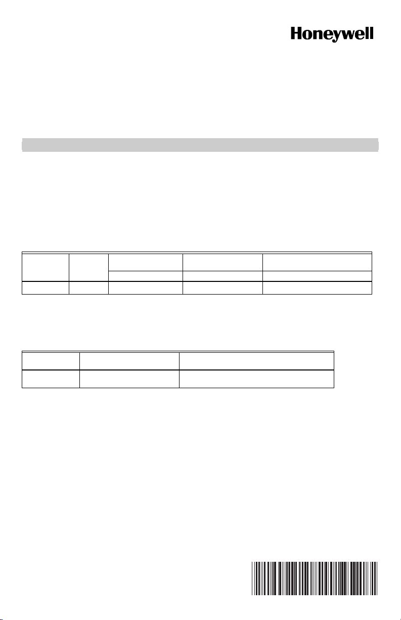
VR9205R SERIES 1000 DIRECT IGNITION GAS CONTROL WITH INTEGRATED GAS/AIR MODULE
WARNING
MIN REGULATOR/
OFFSET ADJUSTMENT
LOW PRESSURE
AIR CONNECTION
HIGH PRESSURE
AIR CONNECTION
MAXIMUM PRESSURE
REGULATOR
TYCO ELECTRONICS
2 PIN POWER
CONNECTOR
MATE-N-LOCK
INLET
1/2 - 14 NPT
3-15/16
(100)
7/8
(22)
1-11/16
(43)
3/8 (9)
INLET
PRESSURE TAP
1/8-27 NPT
Fig. 1. VR9205R Series 1000 Direct Ignition Gas Control.
PLANNING THE INSTALLATION
Fire or Explosion Hazard.
Can cause property damage, severe injury,
or death.
Follow these warnings exactly:
1. Plan the installation as outlined below.
2. Plan for frequent maintenance as described in
the Maintenance section.
Heavy demands are made on the controls when direct
ignition systems are used on central heating equipment in
barns, greenhouses, and commercial properties and on
heating appliances such as commercial cookers,
agricultural equipment, industrial heating equipment and
pool heaters.
Special steps may be required to prevent nuisance
shutdowns and control failure due to frequent cycling,
severe environmental conditions related to moisture,
corrosive chemicals, dust or excessive heat. These
applications require Honeywell Combustion Engineering
review; contact your Honeywell Sales Representative for
assistance.
Review the following conditions that can apply to your
specific installation and follow the precautions suggested.
5 (127)
OUTLET
1/2-14 NPT
OUTLET
PRESSURE TAP
1/8-27 NPT
3-7/16
(87)
REFERENCE
PRESSURE
CONNECTION
1/8
(3)
1-1/16
1-13/16
(27)
1-7/16
(36)
3-3/16 (82)
Frequent Cycling
This control is designed for use on appliances that
typically cycle three to four times an hour only during the
heating season. In year-around applications with greater
cycling rates, the control can wear out more quickly.
Perform a monthly checkout.
Water or Steam Cleaning
If a control gets wet, replace it. If the appliance is likely to
be cleaned with water or steam, protect (cover) the
control and wiring from water or steam flow. Mount the
control high enough above the bottom of the cabinet so it
does not get wet during normal cleaning procedures.
High Humidity or Dripping Water
Dripping water can cause the control to fail. Never install
an appliance where water can drip on the control. In
addition, high ambient humidity can cause the control to
corrode and fail. If the appliance is in a humid
atmosphere, make sure air circulation around the control
is adequate to prevent condensation. Also, regularly
check out the system.
Corrosive Chemicals
Corrosive chemicals can attack the control, eventually
causing a failure. If chemicals are used for routine
cleaning, avoid contact with the control. Where chemicals
are suspended in air, as in some industrial or agricultural
applications, protect the control with an enclosure.
(46)
M29078
69-2305—03 2
VR9205R SERIES 1000 DIRECT IGNITION GAS CONTROL WITH INTEGRATED GAS/AIR MODULE
WARNING
CAUTION
WARNING
Dust or Grease Accumulation
Heavy accumulations of dust or grease can cause the
control to malfunction. Where dust or grease can be a
problem, provide covers for the control to limit
contamination.
Heat
Excessively high temperatures can damage the control.
Make sure the maximum ambient temperature at the
control does not exceed the rating of the control. If the
appliance operates at very high temperatures, use
insulation, shielding, and air circulation, as necessary, to
protect the control. Proper insulation or shielding should
be provided by the appliance manufacturer; verify proper
air circulation is maintained when the appliance is
installed.
INSTALLATION
When Installing this Product…
1. Read these instructions carefully. Failure to follow
them could damage the product or cause a
hazardous condition.
2. Check the ratings given in the instructions and on
the product to make sure the product is suitable for
your application.
3. Installer must be a trained, experienced service
technician.
4. After installation is complete, check out product
operation as provided in these instructions.
Fire or Explosion Hazard.
Can cause property damage, severe injury
or death.
Follow these warnings exactly:
1. Disconnect power supply before wiring to
prevent electrical shock or equipment damage.
2. To avoid dangerous accumulation of fuel gas,
turn off gas supply at the appliance service
valve before starting installation, and perform
Gas Leak Test after installation is complete.
3. Always install a sediment trap in gas supply line
to prevent contamination of gas control.
4. Do not force the on-off switch. Use only your
fingers to operate the on-off switch. Never use
any tools. If the electronic on-off switch does
not operate by hand, the gas control should be
replaced by a qualified service technician.
Force or attempted repair may result in fire or
explosion.
5. Plan the installation as outlined below.
6. Plan for frequent maintenance as described in
the maintenance section.
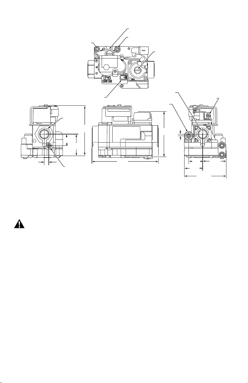
Mounting position
The valve can be mounted 0 to 90 degrees in any
direction from the top of the valve facing up, including
outlet facing upward or downward. See Fig. 2. If the valve
is mounted horizontally; the top of the valve must be even
with or above the center line of the piping.
NOTE: A deviation of more than 3° from the OEM's orig-
inal design mounting orientation can result in an
unacceptable change in gas outlet pressure.
See OEM application installation guide.
To prevent blockage due to condensation, the positive air
pressure connection should not be connected to
combustion products.
TOP OF VALVE
INLET OR
OUTLET
0 TO 90°
HORIZONTIAL
PIPING
VERTICAL
PIPING
Fig. 2. VR9205R Series 1000 mounting.
Equipment Damage Hazard.
Can burn out thermostat or transformer.
Applying a jumper across (or shorting) the valve
coil terminals, even temporarily, can burn out the
thermostat or transformer.
Follow the appliance manufacturers instructions if
available; otherwise use these instructions as a guide.
IMPORTANT
These gas controls are shipped with protective
seals over the inlet and outlet tappings. Do not
remove the seals until ready to install adapters
or connect the piping.
0 TO 90°
M29133
Converting Gas Control from Natural Gas to LP Gas (or LP Gas to Natural Gas)
Fire Or Explosion Hazard.
Can cause property damage, severe injury
or death.
VR9205R cannot be converted between LP or
Natural gas. To convert, see appliance
manufacturer for recommendations.
Install Bushings To Control
If bushings are being installed on the control, mount them
as follows:
Bushings
1. Remove the seal over the control inlet or outlet.
2. Apply a moderate amount of good quality pipe
compound to the bushing, leaving two end threads
bare. On an LP installation, use compound that is
resistant to LP gas. Do not use Teflon tape.
3. Insert the bushing in the control and carefully thread
the pipe into the bushing until tight.
3 69-2305—03
 Loading...