

Honeywell VR8345 Installation Manual
VR8245 and VR8345 Universal
Electronic Ignition Gas Controls
INSTALLATION INSTRUCTIONS
APPLICATION
SPECIFICATIONS
The universal electronic ignition gas controls are used in
gas-fired appliances with capacities up to 300 cu ft/hour
at 1 inch wc pressure drop [8.5 cu m/hour at 0.25 kPa] for
natural gas. These gas controls will operate with a direct
spark (DSI), hot surface (HSI) or intermittent pilot ignition.
The control includes a manual valve, two automatic
operators, a pressure regulator, pilot adjustment, pilot
plug, conduit cover and ignition adapter. Refer to the
following list for the specifications.
Table 1. Gas Capacity.
Size (Inlet x Outlet)
3/4 x 3/4 300 cu ft/hour
1/2 x 1/2 150 cu ft/hour
a
Capacity based on 1000 Btu/cu ft, 0.64 specific gravity natural gas at 1 in. wc pressure drop [37.3 MJ/cu m, 0.64 specific gravity natural gas at 0.25 kPa pressure drop].
Use conversion factors in Table 2 to convert capacities
for other gases.
Table 2. Gas Capacity Conversion Factors.
Gas Specific Gravity
Manufactured 0.60 0.516
Mixed 0.70 0.765
Propane 1.53 1.62
APPROVALS:
American Gas Association Design Certificate:
L2025007.
Canadian Gas Association Design Certificate:
L2025007.
Capacity (at 1 in. wc
pressure drop)
[8.5 cu m/hour]
[4.25 cu m/hour]
Multiply Listed
Capacity By
AMBIENT TEMPERATURE RANGE: -40° to 175°F
[-40° to 79°C].
BODY PATTERN: Straight-through.
IGNITION ADAPTER: Configures device to operate with
direct spark or hot surface ignition.
ELECTRICAL RATINGS:
Voltage and Frequency: 24 Vac, 60 Hz.
Current Draw: See Table 3.
CAPACITY: See Table 1.
a
Minimum Regulated
Capacity
30 cu ft/hour
[0.8 cu m/hour]
20 cu ft/hour
[0.6 cu m/hour]
PIPE ADAPTERS: Includes two 3/4 to 1/2 inch NPT
bushings and one 1/2 to 3/8 inch NPT bushing.
CROSS REFERENCE: See Table 4 for cross reference
information.
Maximum Regulated
[11.8 cu m/hour]
[5.7 cu m/hour]
INSTALLATION
WHEN INSTALLING THIS PRODUCT…
1. Read these instructions carefully. Failure to follow
them could damage the product or cause a hazardous condition.
2. Check the ratings given in the instructions and on
the product to make sure the product is suitable for
your application.
3. The installer must be a trained, experienced service technician.
4. After installation is complete, use these instructions
to check out product operation.
Capacity
415 cu ft/hour
200 cu ft/hour
69-2013
VR8245 AND VR8345 UNIVERSAL ELECTRONIC IGNITION GAS CONTROLS
WARNING
FIRE OR EXPLOSION HAZARD
CAN CAUSE PROPERTY DAMAGE, SEVERE INJURY, OR DEATH
Follow these warnings exactly:
1. Disconnect power supply before wiring to
prevent electrical shock or equipment damage.
2. To avoid dangerous accumulation of fuel gas,
turn off gas supply at the appliance service
valve before starting installation, and perform
Gas Leak Test after completion of installation.
3. When working with a system using intermittent
pilot ignition, do not bend pilot tubing at gas
control or pilot burner after compression fitting
has been tightened because gas leakage at the
connection can result.
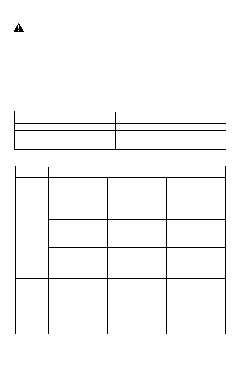
Table 3. Fuel Conversion Kits.
Valve
VR8245M 1/2 x 1/2 Standard .5 393691 394588
VR8345H 3/4 x 3/4 Slow-Opening .7 393691 394588
VR8345M 3/4 x 3/4 Standard .7 393691 394588
VR8345Q 3/4 x 3/4 2-Stage .9 396021 396025
Universal
Replacement Cross Reference
Universal
Service Part Honeywell White-Rodgers Robert-Shaw
VR8245M2530 VR8204A1201, V R8204A1219,
VR8345H4555 VR8305H4013, VR8305H4039,
VR8345M4302 VR8304M4002;
Size
(Inlet and Outlet)
VR8204A2001, VR8204A2175,
VR8204A2803, VR8204A2076
VR8204M1075, VR8204M1091 36E01-204, 36E01-205,
VR8205A2024 36G22-214 722-051 (2000DERHC)
VR8205M1106,
VR8205M2310, VR8205M2443
VR8205H1003
VR8204H1006, VR8304H4503 36E93-304 720-070 (7200IPER-S7C),
VR8204A1201, VR8204A1219,
VR8204A2001, VR8204A2175,
VR8204A2803;
VR8204M1075,
VR8304M3509, VR8304M4507
VR8305M4066,
VR8305M4165,
VR8305M4231, VR8305M3506
VR8205M1106,
VR8205M2310, VR8205M2443
Pressure
Regulator Type Current Draw (A)
Table 4. Cross Reference.
36E01-206, 36E01-305,
36E93-304
36E36-304, 36E22-214 720-079 (7200IPER), 720-080
36E98-304, 36E24-214,
36E52-214
36E01-204, 36E01-205,
36E01-206, 36E01-305,
36E93-304
36C68-423, 36C74-413,
36G22-214
36C68-423, 36E36-304,
36E22-214
4. Always install sediment trap in gas supply line
to prevent contamination of gas control.
5. Do not force the gas control knob. Use only
your hand to turn the gas control knob. Never
use any tools. If the gas control knob will not
operate by hand, call a qualified service
technician to replace the gas control. Force or
attempted repair can result in fire or explosion.
Conversion Kits
Natural Gas - LP LP - Natural Gas
722-079 (2000IPERHC)
(7200IPER-LP)
720-071 (7200IPER-S7C),
720-072 (7200IPER-S7C),
720-073 (7200IPER-LP-S7C)
722-079 (2000IPERHC)
720-051 (7200DER), 722-051
(2000DERHC)
720-079 (7200IPER), 720-080
(7200IPER-LP)
69-2013 2
VR8245 AND VR8345 UNIVERSAL ELECTRONIC IGNITION GAS CONTROLS
Table 4. Cross Reference. (Continued)
Universal
Replacement Cross Reference
Universal
Service Part Honeywell White-Rodgers Robert-Shaw
VR8345Q4563 VR8205Q2555 36E54-214, 36G54-214
VR8304Q4511 36C76-406, 36C76-420,
VR8305Q4146, VR8305Q4500 36D13-208, 36D13-405
36C76-463
36E96-314, 720-082 (7200IPER2-4)
Bushings
CAUTION
Never apply a jumper across or short the valve
coil terminals. This can burn out the heat
anticipator in the thermostat or damage the
electronic intermittent pilot (IP) module.
IMPORTANT:
These gas controls are shipped with protective
seals over inlet and outlet tappings. Do not
remove seals until ready to connect piping.
Follow the appliance manufacturer instructions if
available; otherwise, use the following instructions.
Converting Between Natural And LP Gas
1. Remove seal over gas control inlet or outlet.
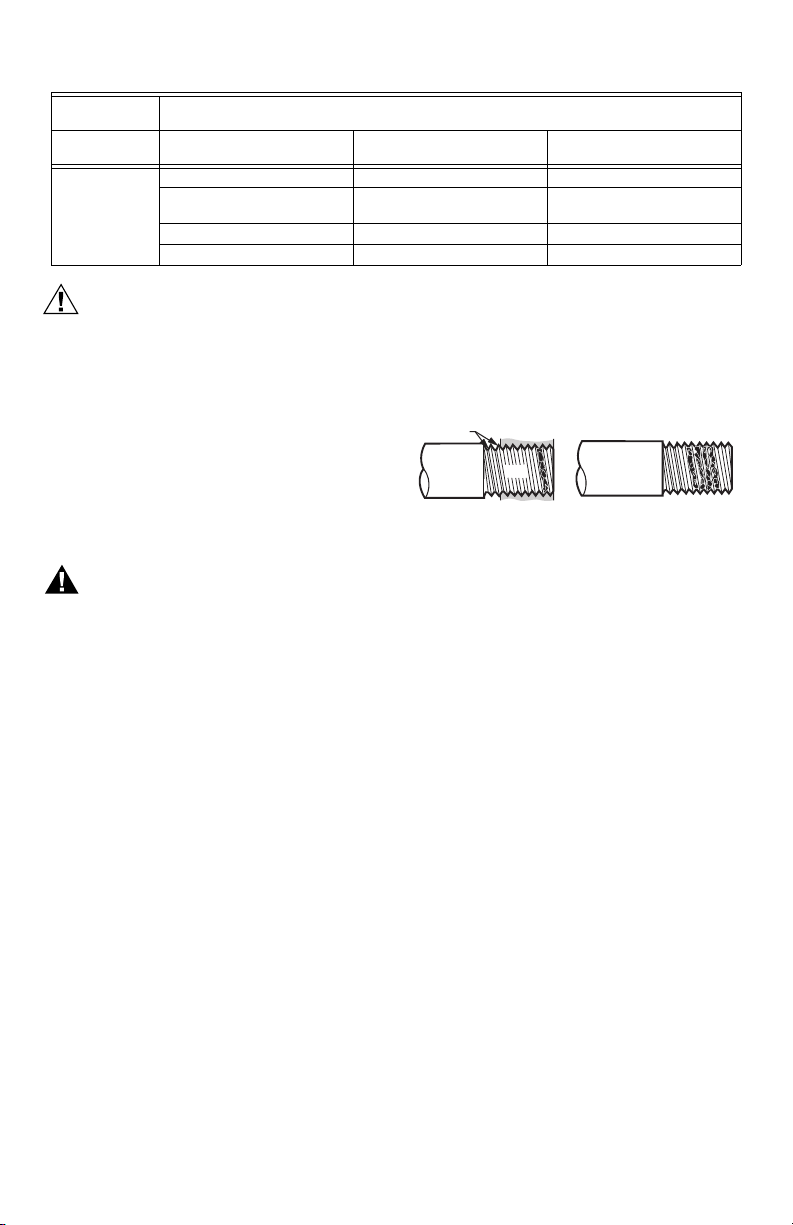
2. Apply moderate amount of good quality pipe com-
pound to bushing, leaving two end threads bare.
See Fig. 1.
3. Insert bushing in gas control and carefully thread
pipe into the bushing until tight.
TWO IMPERFECT
THREADS
THREAD PIPE THE AMOUNT
SHOWN IN TABLE FOR
INSERTION INTO GAS CONTROL
GAS CONTROL
PIPE
APPLY A MODERATE AMOUNT OF
PIPE COMPOUND TO PIPE ONLY
(LEAVE TWO END THREADS BARE).
M3075B
WARNING
FIRE OR EXPLOSION HAZARD
CAN CAUSE PROPERTY DAMAGE, SEVERE
INJURY, OR DEATH
Do not attempt to use a gas control set for natural
gas on LP gas or a gas control set for LP gas on
natural gas.
Convert standard-opening gas controls from natural gas
to LP gas with the conversion kit included with this
TRADELINE® gas control. For conversion kit part
number, see Table 3.
Use Pipe Adapter to Solve Swing Radius
Problems
In some field service applications, space limitations make
it difficult or impossible to thread the gas control onto the
gas supply pipe. This problem can be resolved for many
installations by using a pipe adapter. Install the pipe
adapter on the end of the supply pipe in place of the gas
control by following the same precautions and instructions
that are used for installing the gas control. After the pipe
adapter is installed, attach the gas control to the adapter
as outlined in the Install Pipe Adapters to Gas Control
section.
NOTE: Using a pipe adapter increases the overall length
of the gas control.
Install Pipe Adapter to Gas Control
Install adapter to gas control as follows:
Fig. 1. Use moderate amount of pipe compound.
Location
Locate the combination gas control in the appliance
vestibule on the gas manifold. In replacement
applications, locate the gas control in the same location
as the old control.
Do not locate the gas control where it can be affected by
steam cleaning, high humidity, dripping water, corrosive
chemicals, dust or grease accumulation, or excessive
heat.
For proper operation, follow these guidelines:
• Locate gas control in a well-ventilated area.
• Mount gas control high enough above the cabinet
bottom to avoid exposure to flooding or splashing
water.
• Make sure the ambient temperature does not exceed
the ambient temperature ratings for each component.
• Cover gas control when the appliance is cleaned with
water, steam, or chemicals or to avoid dust and grease
accumulation.
• Avoid locating gas control where exposure to corrosive
chemical fumes or dripping water is possible.
Install Piping to Gas Control
All piping must comply with applicable codes and
ordinances or with the National Fuel Gas Code (ANSI
Z223.1 NFPA No. 54), whichever applies. Tubing
installation must comply with approved standards and
practices.
3 69-2013
VR8245 AND VR8345 UNIVERSAL ELECTRONIC IGNITION GAS CONTROLS
1. Use new, properly reamed pipe free from chips. If
tubing is used, make sure the ends are square,
deburred and clean. Make sure all tubing bends are
smooth and without deformation.
2. Run pipe or tubing to the gas control. If tubing is
used, obtain a tube-to-pipe coupling to connect the
tubing to the gas control.
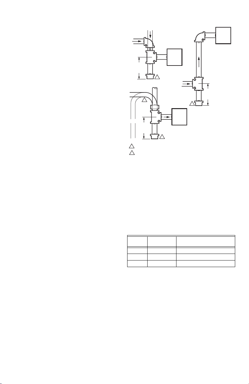
3. Install sediment trap in the supply line to the gas
control. See Fig. 2.
Install Gas Control
1. This gas control can be mounted from 0 to 90
degrees in any direction from the vertical position of
the gas control knob.
2. Mount the gas control so gas flow is in the direction
of the arrow on the bottom of the gas control.
3. Thread pipe the amount shown in Table 5 for insertion into the gas control.
IMPORTANT:
Do not thread pipe too far. Valve distortion or
malfunction can result when the pipe is inserted
too deeply into the gas control.
DROP
HORIZONTAL
3 IN.
(76 MM)
MINIMUM
HORIZONTAL
RISER
3 IN.
(76 MM)
MINIMUM
ALL BENDS IN METALLIC TUBING SHOULD BE SMOOTH.
1
2
CAUTION: SHUT OFF THE MAIN GAS SUPPLY BEFORE REMOVING
END CAP TO PREVENT GAS FROM FILLING THE WORK AREA. TEST
FOR GAS LEAKAGE WHEN INSTALLATION IS COMPLETE.
PIPED
GAS
SUPPLY
GAS
CONTROL
2
DROP
TUBING
1
GAS
SUPPLY
2
GAS
CONTROL
2
RISER
PIPED
GAS
SUPPLY
3 IN.
(76 MM)
MINIMUM
GAS
CONTROL
M8435A
Fig. 2. Install sediment trap.
4. Apply a moderate amount of good quality pipe com-
pound (do not use Teflon tape) to pipe only, leaving
two end threads bare. See Fig. 1. On LP installations, use compound resistant to LP gas.
5. Remove seals over gas control inlet and outlet if
necessary.
6. Connect pipe to gas control inlet and outlet. Use
wrench on the square ends of the gas control. See
Fig. 3 and 4.
69-2013 4
Table 5. NPT Pipe Thread Length in in.
Pipe
Size
Thread Pipe
This Amount
Maximum Depth Pipe Can
Be Inserted Into Control
3/8 9/16 3/8
1/2 3/4 1/2
3/4 13/16 3/4
When working with an intermittent pilot ignition system, go
to Connect Pilot Gas Tubing section next. When installing
on a hot surface or direct spark ignition system, go to the
Wiring section.
 Loading...