

Honeywell VR8305H, VR8305K, VR8305M, VR8305P User Manual
Honeywell
VR8305
Direct Ignition
Combination Gas Control
Application
These direct ignition combination gas controls are used
in gas-fired appliances with capacities up to 300 feet3/hour
at 1 inch wc pressure drop [8.5 meters3/hour at 0.25 kPa]
on natural gas. They include a manual valve, two automatic
operators, and a pressure regulator. See Table 1 for temperature ranges and regulator types.
VR8305 set up for natural gas includes a 393691 LP
Conversion Kit. The kit contains a cap screw, a pressure
regulator adjustment screw, a tapered spring and a conversion label.
CAPACITY:
Size Capacity (at 1 inch Minimum Maximum
(Inlet x Outlet) wc pressure drop
1/2 x 1/2 240 feet3/hour 30 feet3/hour 340 feet3/hour
1/2 x 3/4 270 feet3/hour 30 feet3/hour 370 feet3/hour
3/4 x 3/4 300 feet3/hour 30 feet3/hour 415 feet3/hour
a
Capacity based on 1000 Btu/feet3, 0.64 specific gravity natural gas at 1 inch wc pressure drop [37.3 MJ/meter3, 0.64
specific gravity natural gas at 0.25 kPa pressure drop].
Use conversion factors in Table 3 to convert capacities for
other gasses.
TABLE 1—TEMPERATURE RANGES AND
Model Temperature Regulator
Number Range Type
VR8305H 0° F to 175° F Slow-opening
VR8305K -40° F to 175° F Slow-opening
VR8305M -40° F to 175° F Standard-opening
VR8305P -40° F to 175° F Step-opening
APPROVALS:
American Gas Association design certificate:
UP-70-69A.
Canadian Gas Association design certificate:
UP-70-69A.
Australian Gas Association design certificate:
Applied for.
Delta C: P-70-42A19
REGULATOR TYPES.
Ambient
[-18° C to +79° C]
[-40° C to +79° C]
[-40° C to +79° C]
[-40° C to +79° C]
[6.8 meter3/hour] [0.8 meter3/hour] [9.6 meter3/hour]
[7.6 meter3/hour] [0.8 meter3/hour] [10.5 meter3/hour]
[8.5 meter3/hour] 0.8 meter3/hour] [11.8 meter3/hour]
BODY PATTERN: Straight-through body pattern.
INLET X OUTLET SIZES AVAILABLE: 1/2 x 1/2 inch,
1/2 x 3/4 inch, and 3/4 x 3/4 inch (factory-installed inlet
flange).
ADAPTERS: Adapters available for 1/2 and 3/4 inch
straight and angle connections. Refer to Table 2.
ELECTRICAL RATINGS:
VOLTAGE AND FREQUENCY: 24 Vac, 60 Hz.
THERMOSTAT HEAT ANTICIPATOR SETTING:
0.7A.
CURRENT DRAW: 0.70A.
a
)
Regulated Capacity Regulated Capacity
TABLE 2—FLANGE PART NUMBERS.
Inlet/ Without With
Outlet Flange Hex Hex
Pipe Size Type Wrench Wrench
1/2 inch NPT Straight 393690-6 393690-16
3/4 inch NPT Straight 393690-4 393690-14
NOTE: Flange Kits include one flange with attached O-
ring and four mounting screws.
Gas Gravity Capacity By
Manufactured 0.60 0.516
Mixed 0.70 0.765
Propane 1.53 1.62
Elbow 393690-3 393690-13
Elbow 393690-5 393690-15
TABLE 3—GAS CAPACITY
CONVERSION FACTORS.
Specific Multiply Listed
Part Number
G.G. • Rev. 10-91 • © Honeywell Inc. 1991 • Form Number 69-0626—2
Installation
WHEN INSTALLING THIS PRODUCT…
1. Read these instructions carefully. Failure to follow
them could damage the product or cause a hazardous
condition.
2. Check the ratings given in the instructions and on the
product to ensure the product is suitable for your application.
3. Ensure installer is a trained, experienced service
technician.
4. After installation is complete, use these instructions
to check out product operation.
WARNING
!
FIRE OR EXPLOSION HAZARD
CAN CAUSE PROPERTY DAMAGE,
SEVERE INJURY, OR DEATH
Follow these warnings exactly.
1. Disconnect power supply before wiring to
prevent electrical shock or equipment damage.
2. To avoid dangerous accumulation of fuel gas,
turn off gas supply at the appliance service
valve before starting installation, and perform
Gas Leak Test after completion of installation.
3. Always install sediment trap in gas supply line
to prevent contamination of gas control.
4. Do not force the gas control knob. Use only
your hand to turn the gas control knob. Never
use any tools. If the gas control knob will not
operate by hand, the gas control should be
replaced by a qualified service technician.
Force or attempted repair may result in fire or
explosion.
CONVERTING BETWEEN NATURAL
AND LP GAS
WARNING
!
FIRE OR EXPLOSION HAZARD
CAN CAUSE PROPERTY DAMAGE,
SEVERE INJURY, OR DEATH
1. Do not use a gas control set for natural gas on
LP gas or a gas control set for LP gas on natural
gas.
2. When making conversion, main and pilot
burner orifices MUST be changed to meet
appliance manufacturer specifications.
VR8305 gas controls can be converted from one gas to
another. To convert from natural gas to LP, use the 393691
LP Conversion Kit that is included with the VR8305 Gas
Control. To convert from LP to natural gas, use the 394588
Natural Gas Conversion Kit (order separately). Step-opening gas controls cannot be converted.
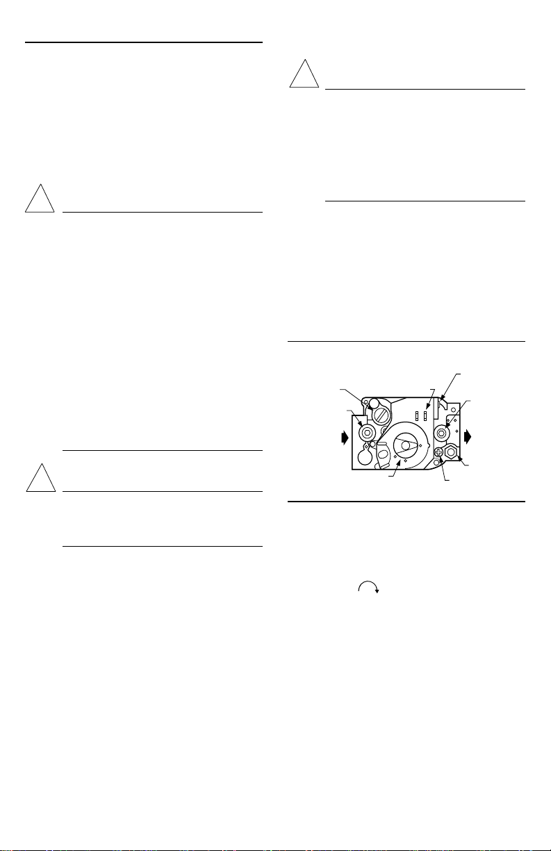
To convert control from one gas to another:
1. Turn off main gas supply to the appliance.
2. Remove the regulator cap screw and pressure regu-
lator adjusting screw. See Fig. 1.
Fig. 1—Top view of gas control.
PRESSURE REGULATOR
ADJUSTMENT (UNDER
CAP SCREW)
INLET
PRESSURE TAP
INLET
CONVENIENCE
TERMINALS (2)
(OPTIONAL)
WIRING
TERMINALS (2)
OUTLET
PRESSURE
TAP
OUTLET
CAUTION
!
Never apply a jumper across or short the valve
coil terminals. This may burn out the heat anticipator in the thermostat or damage the electronic
direct ignition (DI) module.
IMPORTANT: These gas controls are shipped with pro-
tective seals over inlet and outlet tappings. Do not
remove seals until ready to connect piping.
Follow the appliance manufacturer instructions if avail-
able; otherwise, use the Instructions provided below.
GAS CONTROL KNOB
M3043A
3. Remove the existing spring.
4. Insert the replacement spring with tapered end down.
See Fig. 2.
5. Install the new plastic pressure regulator adjustment
screw so that the top of the screw is flush (level) with the
top of the regulator. Turn the pressure regulator adjustment
screw clockwise six complete turns. This provides a
preliminary pressure setting of about 10.0 in. wc [2.5 kPa]
for LP regulator and 3.5 in. wc [0.9 kPa] for natural gas
regulator.
2
PILOT OUTLET
PILOT ADJUSTMENT
(UNDER CAP SCREW)
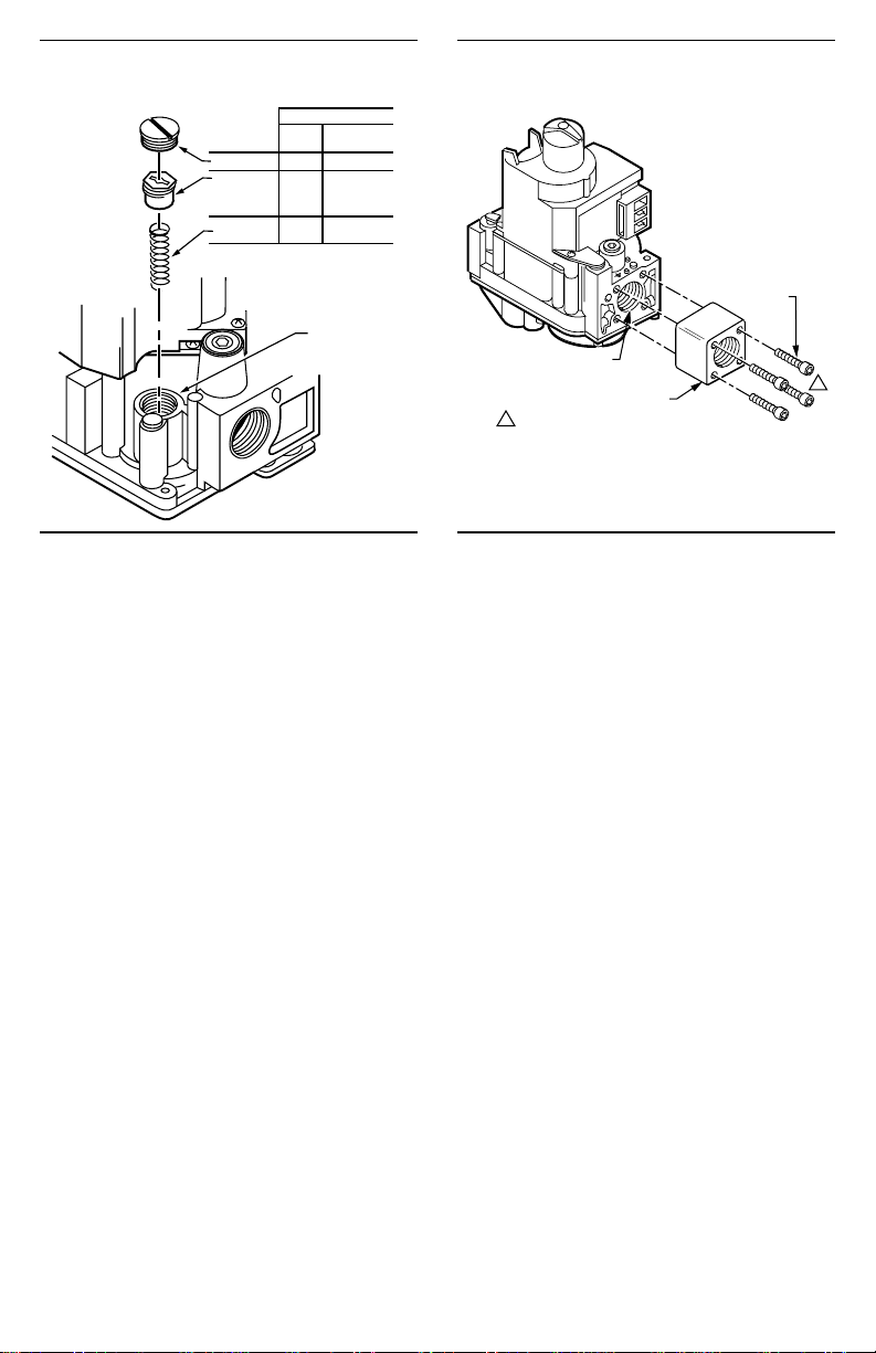
Fig. 2—Installation of conversion kit in regulated
gas control.
COLOR CODE FOR
NATRUAL
LP
GAS
CAP SCREW BLACK SILVER
PRESSURE
REGULATOR
ADJUSTING
SCREW
SPRING
GAS
WHITE WHITE
STAINLESS
RED
STEEL
PRESSURE
REGULATOR
HOUSING
M8083
Fig. 3—Install flange to gas control.
GAS CONTROL OUTLET
1
DO NOT OVERTIGHTEN SCREWS.
TIGHTEN TO 25 INCH POUNDS.
FLANGE
9/64 INCH HEX
SCREWS (4)
M16278
1
6. Check the regulator setting either with a manometer
or by clocking the gas meter. Refer to Startup and Checkout.
7. Install the new cap screw.
8. Mount conversion label on control.
9. Install control and appliance according to appliance
manufacturer instructions.
INSTALL ADAPTERS TO GAS CONTROL
Install adapters to gas control as follows:
Flanges
1. Choose the appropriate flange for your application.
2. Remove seal over gas control inlet or outlet.
3. Ensure the O-ring is fitted in the flange groove. If the
O-ring is not attached or is missing, do not use flange.
4. With O-ring facing gas control, align the screw holes
on the control with the holes in the flange. Insert and tighten
the screws provided with the flange. See Fig. 3. Tighten the
screws to 25 inch-pounds of torque to provide a gas-tight
seal.
Bushings
1. Remove seal over gas control inlet or outlet.
2. Apply moderate amount of good quality pipe compound to bushing, leaving two end threads bare. On LP
installation, use compound resistant to LP gas. Do NOT
use Teflon tape.
3. Insert bushing in gas control and thread pipe carefully into bushing until tight.
USING ADAPTERS TO SOLVE SWING RADIUS
PROBLEMS
In some field service applications, it is difficult or
impossible to thread the control onto the gas supply pipe
because of space limitations. This problem can be resolved
in many instances by using an adapter. The adapter in
installed on the end of the supply pipe in place of the gas
control, following the same precautions and instructions
that are used for installing the gas control. After the adapter
is installed, the gas control is attached to the adapter as
outlined above. Note that using an adapter increases the
overall length of the gas control.
CHOOSE GAS CONTROL LOCATION
Do not locate the gas control where it may be affected
by steam cleaning, high humidity, dripping water, corrosive chemicals, dust or grease accumulation, or excessive
heat. To ensure proper operation, follow these guidelines:
• Locate gas control in a well ventilated area.
• Mount gas control high enough above the cabinet
bottom to avoid exposure to flooding or splashing
water.
• Ensure the ambient temperature does not exceed the
ambient temperature ratings for each component.
• Cover gas control if appliance is cleaned with water,
steam, or chemicals or to avoid dust and grease
accumulation.
• Avoid locating gas control where exposure is possible to corrosive chemical fumes or dripping water.
Locate the gas control in the appliance vestibule on the
gas manifold. In replacement applications, locate the gas
control in the same location as the old gas control.
Install Piping to Gas Control
All piping must comply with local codes and ordinances or with the National Fuel Gas Code (ANSI Z223.1
NFPA No. 54), whichever applies. Tubing installation
must comply with approved standards and practices.
1. Use new, properly reamed pipe free from chips. If
tubing is used, ensure the ends are square, deburred and
clean. All tubing bends must be smooth and without
deformation.
2. Run pipe or tubing to the gas control. If tubing is
used, obtain a tube-to-tube coupling to connect the tubing
to the gas control.
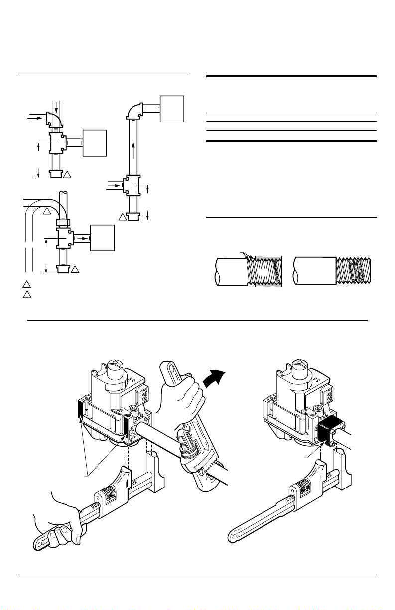
3. Install sediment trap in the supply line to the gas
control. See Fig. 4.
3 69-0626—2
Install Gas Control
1. This gas control can be mounted 0-90 degrees, in any
direction, including vertically, from the upright position of
the gas control knob.
2. Mount the gas control so gas flow is in the direction
of the arrow on the bottom of the control.
Fig. 4—Install sediment trap.
DROP
3 IN.
PIPED
GAS
SUPPLY
GAS
CONTROL
2
DROP
TUBING
1
GAS
SUPPLY
2
GAS
CONTROL
2
HORIZONTAL
3 IN.
(76 MM)
MINIMUM
HORIZONTAL
RISER
(76 MM)
MINIMUM
ALL BENDS IN METALLIC TUBING SHOULD BE SMOOTH.
1
CAUTION: SHUT OFF THE MAIN GAS SUPPLY BEFORE REMOVING
2
END CAP TO PREVENT GAS FROM FILLING THE WORK AREA. TEST
FOR GAS LEAKAGE WHEN INSTALLATION IS COMPLETE.
RISER
PIPED
GAS
SUPPLY
3 IN.
(76 MM)
MINIMUM
GAS
CONTROL
M3077
3. Thread pipe the amount shown in Table 4 for insertion into the gas control. DO NOT THREAD PIPE TOO
FAR. Valve distortion or malfunction may result if the pipe
is inserted too deeply into the gas control.
TABLE 4—NPT PIPE THREAD LENGTH IN
INCHES.
Maximum Depth
Pipe Can Be
Pipe Thread Pipe Inserted Into
Size This Amount Control
3/8 9/16 3/8
1/2 3/4 1/2
3/4 13/16 3/4
4. Apply a moderate amount of good quality pipe
compound (do not use Teflon tape) to pipe only, leaving
two end threads bare. On LP installations, use compound
resistant to LP gas. Refer to Fig. 5.
5. Remove seals over gas control inlet and outlet if
necessary.
Fig. 5—Use moderate amount of pipe compound.
TWO IMPERFECT
THREADS
THREAD PIPE THE AMOUNT
SHOWN IN TABLE FOR
INSERTION INTO GAS CONTROL
GAS CONTROL
PIPE
APPLY A MODERATE AMOUNT OF
PIPE COMPOUND TO PIPE ONLY
(LEAVE TWO END THREADS BARE).
M3075B
Fig. 6—Proper use of wrench on gas control with and without flanges
WHEN FLANGE IS NOT USED
APPLY WRENCH
FROM TOP OR
BOTTOM OF GAS
CONTROL TO
EITHER SHADED AREA
4
WHEN FLANGE IS USED
APPLY WRENCH
TO FLANGE ONLY
M3085A
 Loading...