

Page 1
Place Bar Code Here
VR8304 Intermittent Pilot
Combination Gas Control
INSTALLATION INSTRUCTIONS
APPLICATION
These intermittent pilot gas controls are used in gas-fired
appliances with capacities up to 300 ft
pressure drop (8.5 m
They include a manual valve, two automatic operators,
and a pressure regulator. See Table 1 for temperature
ranges and regulator types.
Table 1. Temperature ranges and regulator types
Model number
VR8304H 0 F to 175 F
VR8304K -40 F to 175 F
VR8304M -40 F to 175 F
VR8304P -40 F to 175° F
3
/h at 0.25 kPa) on natural gas.
Ambient
temperature range Regulator type
(-18 C to +79 C)
(-40 C to +79 C)
(-40 C to +79 C)
(-40 C to +79 C)
3
/hr at 1 in. WC
Slow-opening
Slow opening
Standard-opening
Step-opening
SPECIFICATIONS
Body pattern: Straight-through body pattern.
Inlet x outlet sizes available: 1/2 x 1/2 in., 1/2 x 3/4 in.,
and 3/4 x 3/4 in. (factory-installed inlet flange).
Adapters Adapters available for 3/8, 1/2 and 3/4 in.
straight and angle connections. Refer to Table 2.
Electrical Ratings: voltage and frequency: 24 Vac,
50/60 Hz.
Current Draw: 0.7A.
Capacity: See Table 3.
Approvals:
• American Gas Association Design Certificate:
UP-70-69A
• Canadian Gas Association Design Certificate:
UP-70-69A.
• Australian Gas Association Certificate: Applied for.
• Delta C: Applied for.
Inlet/outlet pipe size Flange type Part number
3/8 inch NPT Straight 393690-11
1/2 inch NPT Elbow 393690-13
3/4 inch NPT Straight 393690-4
NOTE: Flange kits include one flange with attached O-
(inlet x
outlet)
1/2 x 1/2
1/2 X 3/4
3/4 X 3/4
a
Capacity based on 1000 Btu/ft3, 0.64 specific gravity
natural gas at 1 in. WC pressure drop (37.3 MJ/m
0.64 specific gravity natural gas at 0.25 kPa pressure
drop.
Use conversion factors in Table 4 to convert capacities
for other gases.
Manufactured 0.60 0.516
Mixed 0.70 0.765
Propane 1.53 1.62
Table 2. Flange part numbers
Elbow 393690-15
ring and fan mounting screw.
Table 3. Capacity
Capacity at 1 in.
Size
WC pressure
a
drop
3
/hr
240 ft
3
/hr)
(6.8 m
3
/hr
270 ft
3
/hr)
(7.6 m
3
/hr
300 ft
3
/hr)
(8.5 m
Table 4. Gas capacity conversion factors
Gas Specific gravity
Minimum
regulated
capacity
3
30 ft
/hr
3
(0.8 m
3
30 ft
/hr
3
(0.8 m
3
30 ft
/hr
3
(0.8 m
Maximum
regulated
capacity
3
340 ft
/hr)
(9.6 m
3
370 ft
/hr)
(10.5 m
3
415 ft
/hr)
(11.8 m
Multiply listed
capacity by
/hr
3
/hr
/hr
/hr)
3
3
3
/hr)
/r)
,
69-0625—03
Page 2
VR8304 INTERMITTENT PILOT COMBINATION GAS CONTROL
WARNING
CAUTION
WARNING
INSTALLATION
When installing this product ...
1. Read these instructions carefully. Failure to follow
them could damage the product or cause a
hazardous condition.
2. Check the ratings given in the instructions and on
the product to ensure the product is suitable for
your application.
3. Ensure installer is a trained, experienced service
technician.
4. After installation is complete, use these instructions
to check out product operation.
Fire or explosion hazard. Can cause property
damage, severe injury, or death.
Follow these warnings exactly:
1. Disconnect power supply before wiring to
prevent electrical shock or equipment damage.
2. To avoid dangerous accumulation of fuel gas,
turn off gas supply at the appliance service
valve before starting installation, and perform
the gas leak test after completion of installation.
3. Do not bend pilot tubing at gas control or pilot
burner after compression fitting has been
tightened, or gas leakage at the connection
may result.
4. Always install sediment trap in gas supply line
to prevent contamination of gas control.
5. Do not force the gas control knob. Use only
your hand to turn the gas control knob. Never
use tools. If the gas control knob will not
operate by hand, the gas control should be
replaced by a qualified service technician.
Force or attempted repair may result in fire or
explosion.
Never apply a jumper across or short the valve
coil terminals. This may burn out the heat
anticipator in the thermostat or damage the
electronic intermittent pilot (IP) module.
IMPORTANT
These gas controls are shipped with protective
seals over inlet and outlet tappings. Do not
remove the seals until you are ready to connect
piping.
Follow the appliance manufacturer’s instructions if available; otherwise, use the instructions
provided below.
Converting Between Natural and LP Gas
Fire or explosion hazard. Can cause property
damage, severe injury, or death.
Do not attempt to use a gas control set for
natural gas on LP gas or a gas control set for
LP gas on natural gas.
To convert a gas control from natural gas to LP gas or
from LP gas to natural gas, contact your Honeywell
representative.
Standard- or slow-opening gas controls are converted
from one gas to another with a conversion kit (order
separately). Order Part Number 393691 to convert from
natural to LP gas. Order Part Number 394588 to convert
from LP to natural gas. Step-opening gas controls cannot
be converted.
Install Adapters to Gas Control
Install adapters to the gas control as follows:
Flanges
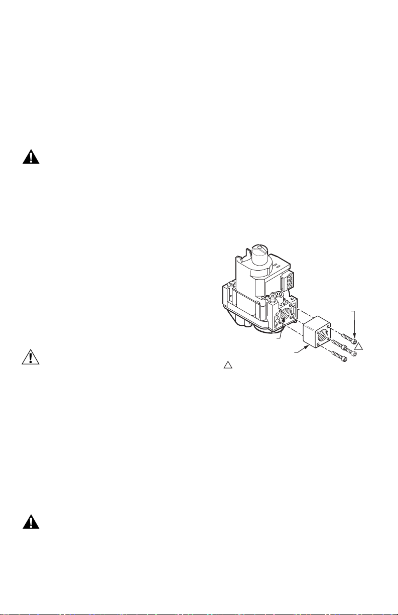
1. Choose the appropriate flange for your application.
2. Remove the seal over the gas control inlet or outlet.
3. Ensure the O-ring is fitted in the groove of the
flange. If the O-ring is not attached or is missing, do
not use the flange.
4. With the O-ring facing the gas control, align the
screw holes on the gas control with the holes in the
flange. Insert and tighten the screws provided with
the flange. See Fig. 1. Tighten the screws to 25 in.
pounds of torque to provide a gas-tight seal.
9/64 INCH HEX
SCREWS (4)
GAS CONTROL OUTLET
FLANGE
1 DO NOT OVERTIGHTEN SCREWS.
TIGHTEN TO 25 INCH POUNDS.
Fig. 1. Install flange to gas control.
1
M3087
Bushings
1. Remove the seal over the gas control inlet or outlet.
2. Apply moderate amount of good quality pipe com-
pound to the bushing, leaving two end threads bare.
On LP installation, use a compound resistant to LP
gas. Do not use Teflon tape.
3. Insert the bushing into the gas control and thread
the pipe carefully into the bushing until tight.
Using Adapters to Solve Swing Radius Problems
In some field service applications, it is difficult or
impossible to thread the gas control onto the gas supply
pipe because of space limitations. This problem can be
resolved in many instances by using an adapter. The
adapter is installed on the end of the supply pipe in place
of the gas control, following the same precautions and
instructions that are used for installing the gas control.
After the adapter is installed, the gas control is attached to
the adapter as outlined above. Note that using an adapter
increases the overall length of the gas control.
69-0625—03 2
Page 3
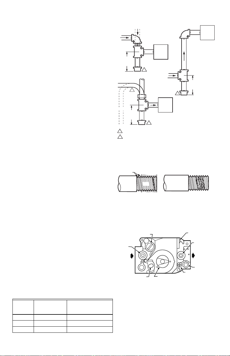
Choose Gas Control Location
GAS
CONTROL
GAS
CONTROL
HORIZONTAL
DROP
PIPED
GAS
SUPPLY
PIPED
GAS
SUPPLY
3 IN.
(76 MM)
MINIMUM
3 IN.
(76 MM)
MINIMUM
RISER
GAS
CONTROL
TUBING
GAS
SUPPLY
HORIZONTAL
DROP
3 IN.
(76 MM)
MINIMUM
RISER
M3077A
2
1
2
2
1
2
ALL BENDS IN METALLIC TUBING SHOULD BE SMOOTH.
CAUTION: SHUT OFF THE MAIN GAS SUPPLY BEFORE REMOVING
END CAP TO PREVENT GAS FROM FILLING THE WORK AREA. TEST
FOR GAS LEAKAGE WHEN INSTALLATION IS COMPLETE.
OUTLET
PRESSURE
TAP
INLET
OUTLET
WIRING
TERMINALS (3)
INLET
PRESSURE
TAP
PRESSURE REGULATOR
ADJUSTMENT
(UNDER CAP SCREW)
PILOT OUTLET
PILOT ADJUSTMENT
(UNDER CAP SCREW)
GAS CONTROL
KNOB
RED
RESET BUTTON
M1639C
Do not locate the gas control where it may be affected by
steam cleaning, high humidity, dripping water, corrosive
chemicals, dust or grease accumulation, or excessive heat.
To ensure proper operation, follow these guidelines.
• Locate the gas control in a well ventilated area.
• Mount the gas control high enough above the
cabinet bottom to avoid exposure to flooding or
splashing water.
• Ensure the ambient temperature does not
exceed the ambient temperature ratings for each
component.
• Cover the gas control if the appliance is cleaned
with water, steam, or chemicals or to avoid dust
and grease accumulation.
• Avoid locating the gas control where exposure to
corrosive chemical fumes or dripping water is
likely.
Locate the gas control in the appliance vestibule on the
gas manifold. In replacement applications, locate the gas
control in the same location as the old gas control.
Install Piping to the Gas Control
All piping must comply with local codes and ordinances or
with the National Fuel Gas Code (ANSIZ223.1 NFPA No.
54), whichever applies. Tubing installation must comply
with approved standards and practices.
1. Use new, properly reamed pipe free of chips. If tubing is used, ensure the ends are square, deburred
and clean. All tubing bends must be smooth and
without deformation.
2. Run a pipe or tubing to the gas control. If tubing is
used, obtain a tube-to-pipe coupling to connect the
tubing to the gas control.
3. Install a sediment trap in the supply line to the gas
control. See Fig. 2.
Install the Gas Control
1. Mount the gas control 0–90 degrees in any direction
from the upright position of the gas control knob,
including vertically.
Mount the gas control so that gas flow is in the direc-
2.
tion of the arrow on the bottom of the gas control.
3. Thread the pipe the amount shown in Table 5 for
insertion into the gas control or adapter. DO NOT
THREAD THE PIPE TOO FAR. Valve distortion or
malfunction may result if the pipe is inserted too
deeply into the gas control.
4. Apply a moderate amount of good quality pipe compound (DO NOT use Teflon tape) to the pipe only,
leaving two end threads bare. On LP installations,
use a compound resistant to LP gas. Refer to Fig. 3.
5. Remove the seals over the gas control inlet and
outlet if necessary.
Connect the pipe to the gas control inlet and outlet.
6.
Use a wrench on the square ends of the gas control. If
an adapter is used, place the wrench on the adapter
rather than the gas control. Refer to Figs. 4 and 5.
Table 5. NPT pipe thread length (inches)
Pipe size
318 9/16 3/8
1/2 3/4 1/2
3/4 13/16 3/4
Thread pipe this
amount
Maximum depth pipe
can be inserted into the
control
VR8304 INTERMITTENT PILOT COMBINATION GAS CONTROL
Fig. 2. Install a sediment trap.
TWO IMPERFECT
THREADS
THREAD PIPE THE AMOUNT
SHOWN IN TABLE FOR
INSERTION INTO GAS CONTROL
GAS CONTROL
PIPE
APPLY A MODERATE AMOUNT OF
PIPE COMPOUND TO PIPE ONLY
(LEAVE TWO END THREADS BARE).
M3075B
Fig. 3. Use a moderate amount of pipe compound.
Fig. 4. Top view of gas control.
Connect Pilot Gas Tubing
1. Cut tubing to desired length and bend as necessary
for routing to the pilot burner. Do not make sharp
bends or deform the tubing. Do not bend tubing at
gas control or pilot burner after compression fitting
has been tightened, as this may result in gas leakage at the connection.
Square off and remove burrs from the ends of tubing.
2.
3 69-0625—03
Page 4

VR8304 INTERMITTENT PILOT COMBINATION GAS CONTROL
WARNING
GAS CONTROL
TIGHTEN NUT ONE TURN
BEYOND FINGER-TIGHT.
TO PILOT
BURNER
FITTING BREAKS OFF AND CLINCHES
TUBING AS NUT IS TIGHTENED.
M3076B
WHEN FLANGE IS NOT USED
APPLY WRENCH
FROM TOP OR
BOTTOM OF GAS
CONTROL TO
EITHER SHADED AREA
Fig. 5. Proper use of a wrench on a gas control with and without flanges.
3. Unscrew compression titling from the pilot outlet
(Fig. 4).
4. Slip the compression fitting over the tubing and
slide out of the way.
5. Push the tubing into the pilot gas tapping on the
outlet end of the control until it bottoms. While holding tubing all the way in, slide compression flitting
into place and engage threads—turn until finger
tight. Then tighten one more turn with a wrench. Do
not overtighten. Refer to Fig. 6.
6. Connect other end of the tubing to pilot burner
according to the pilot burner’s manufacturer’s
instructions.
NOTE: When replacing a gas control, cut off old com-
pression fitting and replace it with the new compression fitting provided on the gas control.
Never use the old compression fitting as it may
not provide a gas-tight seal.
WHEN FLANGE IS USED
APPLY WRENCH
TO FLANGE ONLY
M3079
2. Connect the control circuit to the gas control terminals. See Figs. 4 and 7 or 8.
3. Adjust the thermostat heat anticipator to 0.70 rating
stamped on valve operator.
STARTUP AND CHECKOUT
Fire or explosion hazard. Can cause property
damage, severe injury, or death.
1. Do not force the gas control knob. Use only
your hand to turn the gas control knob. Never
use tools.
2. If the gas control knob will not operate by hand,
the gas control should be replaced by a
qualified service technician.
Fig. 6. Always use new compression fitting.
WIRING
Follow the wiring instructions furnished by the appliance
manufacturer if available or use the general instructions
provided below.
All wiring must comply with applicable electrical codes
and ordinances.
Disconnect power supply before making wiring connections
to prevent electrical shock or equipment damage.
1. Check the power supply rating on the gas control
and ensure it matches the available supply. Install
transformer, thermostat, and other controls as
required.
69-0625—03 4
Gas Control Knob Settings
The gas control knob has two settings:
OFF—prevents pilot and main burner gas flow.
ON—permits gas to flow into the control body. Under
control of the thermostat and intermittent pilot module,
pilot and main burner gas flow is permitted.
NOTE: Gas controls are shipped with the gas control
knob in the ON position.
Turn on the System
Rotate the gas control knob counterclockwise to ON.
Turn on the Main Burner
Follow the instructions provided by the appliance
manufacturer or turn the thermostat up to call for heat.
Page 5

VR8304 INTERMITTENT PILOT COMBINATION GAS CONTROL
2
THERMOSTAT
OR CONTROLLER
AIR PROVING
COMBUSTION
AIR BLOWER
RELAY
L1
1
2
3
4
(HOT)
POWER SUPPLY. PROVIDE DISCONNECT MEANS AND OVERLOAD PROTECTION AS REQUIRED.
ALTERNATE LIMIT CONTROLLER LOCATION.
MAXIMUM CABLE LENGTH 3 FT (0.9M).
CONTROLS IN 24V CIRCUIT MUST NOT BE IN GROUND LEG TO TRANSFORMER.
SWITCH
COMBUSTION
AIR BLOWER
MOTOR
L2
24V
(1) (GND)
24V (2)
S86 MODULE
(BURNER)
3
4
MV
PV/MV
PV
GND
Q345, Q346, Q348,
Q362, Q381
PILOT BURNER/
IGNITER-SENSOR
Fig. 7. VR8304 wiring connections in an intermittent ignition system with S86.
S8610F,H
VR8304
COMBINATION
GAS CONTROL
PV
PV/MV
MV
MV MV/PV PV
GND
(BURNER)
24V
GND
24V TH-W
1
PILOT GAS
SUPPLY
VENT
4
DAMPER
PLUG
LIMIT
CONTROLLER
GAS CONTROL
TERMINALS
PV
PV/MV
MV
PILOT BURNER
GROUND
WIRING
HARNESS
M18851
L1
(HOT)
L2
SPARK
THERMOSTAT
2
IGNITERSENSOR
PILOT
BURNER
GROUND
POWER SUPPLY. PROVIDE DISCONNECT MEANS AND OVERLOAD PROTECTION AS REQUIRED.
1
ALTERNATE LIMIT CONTROLLER LOCATION.
2
CONTROLS IN 24V CIRCUIT MUST NOT BE IN GROUND LEG TO TRANSFORMER.
3
REMOVE PLUG ONLY IF USING VENT DAMPER. FUSE BLOWS ON STARTUP WHEN PLUG IS REMOVED
4
AND VENT DAMPER WIRING HARNESS IS INSTALLED; THEN MODULE WILL OPERATE ONLY WHEN VENT
DAMPER IS CONNECTED.
3
LIMIT
CONTROLLER
D80D VENT
DAMPER
L1
(HOT)
L2
Fig. 8. VR8304 wiring connections in intermittent ignition system with S8600.
5 69-0625—03
1
M1507
Page 6

VR8304 INTERMITTENT PILOT COMBINATION GAS CONTROL
WARNING
CAUTION
PROPER FLAME
ADJUSTMENT
IGNITERSENSOR
M3080A
3/8 TO 1/2 INCH
(10 TO 13 mm)
Perform Gas Leak Test
Fire or explosion hazard. Can cause property
damage, severe injury, or death.
Check for gas leaks with a rich soap and water
solution any time work is done on a gas
control.
Gas leak test
1. Paint all pipe connections upstream of the gas con-
trol with a rich soap and water solution. Bubbles
indicate a gas leak.
If a gas leak is detected, tighten the pipe connection.
2.
3. Stand clear while lighting the main burner to prevent
injury caused from hidden gas leaks, which could
cause flashback in the appliance vestibule. Light
the main burner.
4. With the main burner in operation, paint all pipe
joints (including adapters) and the gas control inlet
and outlet with a rich soap and water solution.
5. If another gas leak is detected, tighten adapter
screws, joints, and pipe connections.
6. Replace the part if the gas leak cannot be stopped.
Adjust the Pilot Burner Flame
The pilot flame should envelop 3/8 to 1/2 in. (10-13 mm) of
the igniter sensor tip. See Fig. 9. To adjust the pilot flame:
1. Remove the pilot adjustment cover screw. Refer to
Fig. 4.
2. Turn the inner adjustment screw clockwise to
decrease or counterclockwise to increase the
pilot flame.
3. Always replace the cover screw after adjustment
and tighten firmly to ensure proper operation.
Fig. 9. Proper flame adjustment.
Check and Adjust Gas Input to Main Burner
1.
Do not exceed the input rating stamped on the
appliance nameplate or the manufacturer’s
recommended burner orifice pressure for the size of
orifice(s) used. Ensure the main burner primary air
supply is properly adjusted for complete combustion
(refer to the appliance manufacturer’s instructions).
2. IF CHECKING GAS INPUT BY CLOCKING THE
GAS METER:
• Ensure that the only gas flow through the meter
is that of the appliance being tested.
• Ensure that other appliances are turned off and
• Convert the flow rate to Btuh as described in the
69-0625—03 6
that their pilot burners are extinguished (or deduct
their gas consumptions from the meter reading).
Gas Controls Handbook (form number 70-2602)
and compare to the Btuh input rating on the
appliance nameplate.
3. IF CHECKING GAS INPUT WITH A MANOMETER
(PRESSURE GAUGE):
• Ensure the gas control knob is in the PILOT
position before removing the outlet pressure tap
plug to connect the manometer.
• Turn the gas control knob back to PILOT when
removing the manometer and replacing the
outlet pressure tap plug.
• Shut off the gas supply at the appliance service
valve or, for LP gas, at the gas tank before
removing the outlet pressure tap plug and before
disconnecting the manometer and replacing the
outlet pressure tap plug.
• Perform the gas leak test at the inlet pressure
tap plug.
Standard-opening and slow-opening
pressure regulator
1. The gas control outlet pressure should match the
manifold pressure listed on the appliance nameplate.
2. With the main burner operating, check the gas control flow rate using the meter docking method or
check the gas pressure using a manometer connected to the gas control outlet pressure tap. Refer
to Fig. 4.
If necessary, adjust the pressure regulator to match the
3.
appliance rating. Refer to Table 5 or 6 for the factory
set nominal outlet pressures and adjustment ranges.
a. Remove the pressure regulator adjustment cap
and screw.
b. b.Using a screwdriver, turn the inner adjustment
screw clockwise to increase, or counterclockwise to decrease, the main burner gas
pressure.
c. Always replace the cap screw and tighten firmly
to ensure proper operation.
If the desired outlet gas pressure or gas flow rate can-
4.
not be achieved by adjusting the gas control, check
the gas control inlet pressure using a manometer at
the inlet pressure tap. If the inlet pressure is in the normal range (refer to Table 6 or 7), replace the gas control. Otherwise take the necessary steps to provide
proper gas pressure to the gas control.
Step-opening pressure regulator
1.
The gas control outlet pressure should match the
manifold pressure listed on the appliance nameplate.
2. With the main burner operating, check gas control
flow rate using the meter clocking method or check
the gas pressure using a manometer connected to
the gas control outlet pressure tap. Refer to Fig. 4.
If necessary, adjust the pressure regulator to match
3.
the appliance rating. Refer to Table 5 or 6 for factoryset nominal outlet pressures and adjustment ranges.
a. Remove pressure regulator adjustment cap
screw.
b. Using a screwdriver, turn the inner adjustment
screw clockwise to increase or counterclockwise to decrease the main burner gas
pressure.
c. Always replace the cap screw and tighten firmly
to ensure proper operation.
If the desired outlet pressure or flow rate cannot be
4.
achieved by adjusting the gas control, check the inlet
pressure using a manometer at inlet pressure tap or
upstream of the gas control. If the inlet pressure is in the
normal range (refer to Table 6 or 7), replace the existing
gas control. Otherwise, take the necessary steps to
provide proper gas pressure to the gas control.
Page 7

VR8304 INTERMITTENT PILOT COMBINATION GAS CONTROL
WARNING
WARNING
5.
Carefully check main burner lightoff at the step pressure. Ensure the main burner lights smoothly and without flashback to the orifice and that all ports remain lit.
Cycle the main burner several times, allowing at least
Table 6. Pressure regulator specification (pressures in inches WC)
Model Type of gas
Standard, slow-opening Natural 5.0–7.0 – 3.5 – 3.0–5.0
LP 12.0–14.0 – 11.0 – 8.0–12.0
Step-opening Natural 5.0–7.0 0.9 3.5 – 3.0–5.0
LP 12.0–14.0 2.2 11.0 – 8.0–12.0
Table 7. Pressure regulator specification (pressures in kPa)
Model Type of gas
Standard, slow-opening Natural 1.2–1.7 – 0.9 – 0.7-1.2
LP 2.9–3.9 – 2.7 – 2.0-3.0
Step-opening Natural 1.2–1.7 0.2 0.9 – 0.7-1.2
LP 2.9–3.9 0.9 2.7 – 2.0-3.0
Nominal inlet
pressure range
Nominal inlet
pressure range
30 seconds between cycles for the regulator to
resume the step function. Repeat after allowing the
main burner to cool. Readjust the full rate outlet pressure if necessary to improve lightoff characteristics.
Outlet Pressure
Nominal factory setting Setting range
Step Full rate Step Full rate
Outlet Pressure
Nominal factory setting Setting range
Step Full rate Step Full rate
Check Safety and Shutdown Performance
Fire or explosion hazard. Can cause property
damage, severe injury or death.
Perform the safety shutdown test any time
work is done on a gas system.
Read steps 1
safety shutdown or safety lockout tests recommended for
the intermittent pilot (IP) module. Where they differ, use
the procedure recommended for the module.
1. Turn gas supply off.
2. Set the thermostat or the controller above room
3.
4. If the module has timed ignition, time the length of
5. After the module locks out, open the gas control
6. Set the thermostat below room temperature and
7. Operate the system through one complete cycle to
–7 below before starting and compare to the
temperature to call for heat.
Watch for spark at the pilot burner either immediately
or following prepurge. See IP module specifications.
spark operation. See IP module specifications.
knob and ensure there is no pilot or main burner
gas flow. With modules that continue to spark until
pilot lights or system is shut down manually, the
pilot should light when gas control knob is opened.
wait one minute.
ensure all controls operate properly.
MAINTENANCE
Fire or explosion hazard. Can cause property
damage, severe injury or death.
Improper cleaning or reassembly may cause
gas leakage. When cleaning, ensure that the
control is reassembled properly and perform
the gas leak test.
Regular preventive maintenance is important in
applications that place a heavy load on system controls,
such as in the commercial cooking and agricultural and
manufacturing industries, because:
• In many such applications, particularly
commercial cooking, the equipment operates
100,000 to 200,000 cycles per year. Such heavy
cycling can wear out the gas control in one to
two years.
• Exposure to water, dirt, chemicals and heat can
damage the gas control and shut down the
control system.
The maintenance program should include regular
checkout of the gas control as outlined under “STARTUP
AND CHECKOUT” on page 4, and the control system as
described in the appliance manufacturer’s literature.
Maintenance frequency must be determined individually
for each application. Some considerations are:
• Cycling frequency. Appliances that might cycle
100,000 times annually should be checked
monthly.
• Intermittent use. Appliances that are used
seasonally should be checked before shutdown
and again before the next use.
• Consequence of unexpected shutdown. Where
the cost of an unexpected shutdown would be
high, the system should be checked more often.
• Dusty, wet, or corrosive environment. Since
these environments can cause the gas control to
deteriorate more rapidly, the system should be
checked more often.
The gas control should be replaced if:
• It does not perform properly on checkout or
troubleshooting.
• It is likely to have operated for more than
200,000 cycles.
• The gas control knob is hard to turn or push
down or it fails to pop back up when released.
7 69-0625—03
Page 8

VR8304 INTERMITTENT PILOT COMBINATION GAS CONTROL
WARNING
CAUTION
WARNING
Service
Fire or explosion hazard. Can cause property
damage, severe injury, or death.
Do not disassemble the gas control; it
contains no replaceable components.
Attempted disassembly or repair may damage
the gas control.
Do not apply a jumper across or short the
valve coil terminals. Doing so may burn out
the heat anticipator in the thermostat or
damage the electronic module.
IMPORTANT
Allow 60 seconds after shutdown before reenergizing the step-opening module to ensure
lightoff at steppressure.
IF MAIN BURNER WILL NOT COME ON WITH CALL
FOR HEAT
1. Ensure the gas control knob is in the ON position.
2. Adjust the thermostat several degrees above room
temperature.
3. Using an AC voltmeter, check for 24V at gas
control.
• If pilot lights, measure across MV/PV and MV.
• If pilot does not light, measure across MV/PV
and PV before safety lockout occurs.
4. If voltage is incorrect or not present, check control
circuit for proper operation.
5. If 24V is present, replace the gas control.
INSTRUCTIONS TO THE HOMEOWNER
Fire or explosion hazard. Can cause property
damage, severe injury, or death.
Follow these warnings exactly:
1. Pilot flame is lit automatically. Do not light the pilot
flame manually.
2. Before lighting the pilot burner flame, smell around
the appliance for gas. Be sure to smell close to the
floor because LP gas is heavier than air.
3. IF YOU SMELL GAS:
• Turn off the gas supply at the appliance service
valve on LP gas systems, turn off gas supply at
the gas tank.
• Do not light any appliances in the house.
• Do not touch electrical switches or use the
phone.
• Leave the building and use a neighbor’s phone
to call your gas supplier.
• If you cannot reach your gas supplier, call the
fire department.
4. Do not force the gas control knob. Use only your
hand to push down or turn the gas control knob.
Never use tools. If the gas control knob will not
operate by hand, the gas control should be
replaced by a qualified service technician. Force or
attempted repair may result in a fire or explosion.
5. The gas control must be replaced in case of any
physical damage, tampering, bent terminals, missing or broken parts, stripped threads, or evidence
of exposure to heat.
IMPORTANT
Follow the operating instructions provided by
the manufacturer of your heating appliance. The
information below will be of assistance in a typical gas control application, but the specific controls used and the procedures outlined by the
manufacturers of your appliance may differ,
requiring special instructions.
STOP! READ THE WARNINGS ABOVE!
The pilot flame is lit automatically. If the appliance does
not turn on when the thermostat is set several degrees
above the room temperature, follow these instructions.
1. Set the thermostat to its lowest setting to reset the
safety control.
2. Disconnect all electric power to the appliance.
3. Remove the gas control access panel.
4. Push in the gas control knob slightly and turn
clockwise to OFF.
5. Wait five minutes to clear out any unburned gas. If
you then smell gas, STOP! Follow Step 3 in the
Warnings above. If you do not smell gas, continue
with the next step.
6. Turn the gas control knob counterclockwise to
PILOT.
7. Turn the gas control knob counterclockwise to
ON.
8. Replace the gas control access panel.
9. Reconnect all electric power to the appliance.
10. Set the thermostat to the desired setting.
11. If the appliance does not turn on, set the gas con-
trol knob to OFF and contact a qualified service
technician for assistance.
Turning off the Appliance
VACATION SHUTDOWN—Set the thermostat to the
desired room temperature while you are away.
COMPLETE SHUTDOWN—Push the gas control
knob in slightly and turn clockwise to OFF. Do not
force. Appliance will completely shut off. Follow the
lighting procedures above to resume normal
operation.
Automation and Control Solutions
Honeywell International Inc. Honeywell Limited-Honeywell Limitée
1985 Douglas Drive North 35 Dynamic Drive
Golden Valley, MN 55422 Toronto, Ontario M1V 4Z9
customer.honeywell.com
® U.S. Registered Trademark
© 2008 Honeywell International Inc.
69-0625—03 K.K. Rev. 10-08
Printed in Mexico
 Loading...