

Honeywell VR8204A, VR4204M, VR8204M, VR8204C, VR8204P Series Manual
...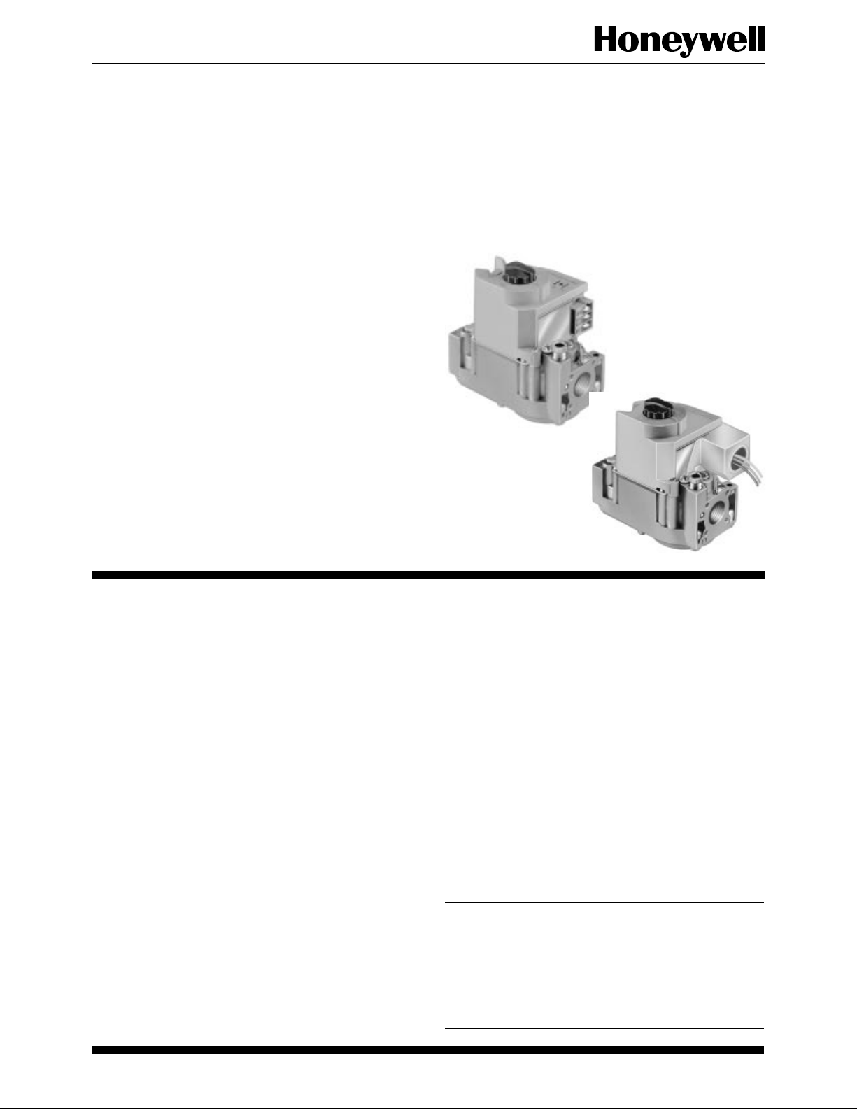
VR8204; VR4204
Intermittent Pilot Dual Automatic
Valve Combination Gas Controls
The VR8204 AND VR4204 Intermittent Pilot
Dual Automatic Valve Combination Gas Controls
are used in gas-fired, intermittent pilot appliances. The controls include a safety shutoff, a
manual valve, two automatic operators, a pressure regulator, a pilot adjustment screw and a
conduit cover (VR4204 only).
■ VR8204 used with S8600, S8610 and S8620 Control
Modules.
■ VR4204 used with 120 Vac intermittent ignition mod-
ules.
■ VR8204 for use with 24 Vac heating appliances and
VR4204 for use with 120 Vac heating appliances that
burn natural or manufactured gas, or liquified petroleum
(LP) gas.
■ Capacity rated at 150 cfh at 1 in. wc pressure drop
[4.2 m3/hr at 0.25 kPa].
■ Solenoid-operated first automatic valve opens on ther-
mostat call for heat and closes when call for heat ends.
■ Diaphragm-operated second automatic valve opens un-
der control of the regulator and closes if gas or power
supply is interrupted.
■ Two-position gas control knob has ON and OFF posi-
tions.
■ All adjustments and wiring connections are accessible
from top of the control.
■ Compact size.
■ Straight-through body pattern; right angle adapters avail-
able for inlet and outlet.
■ 1/2 in. inlet and 1/2 in. outlet; adapters available for 3/8
or 3/4 in.
■ Adjustable servo regulator effectively maintains almost
constant gas output pressure under wide fluctuations in
gas supply pressure.
■ Inlet and outlet screens included.
■ Pilot filter included.
■ Wiring terminal block color-coded orange to indicate
intermittent pilot control.
■ May be installed at any angle between 0 and 90 degrees
from the upright position, including vertically.
■ 1/4 in. male quick-connect terminals for electrical con-
nections.
■ 0° F to 175 F° [-18° C to +79° C] temperature range
standard; -40° F to 175° F [-40° C to +79° C] available.
■ lnlet and outlet pressure taps provided; both taps accessible from top of control.
■ Standard-, slow- and step-opening models available.
CONTENTS
Specifications............................................... 2
Ordering Information .................................. 2
Installation................................................... 4
Startup and Checkout .................................. 8
Maintenance ..............................................10
Operation ................................................... 10
Service........................................................ 13
G. S. • Rev. 1-94 • ©Honeywell Inc. 1994 • Form Number 68-0047—2
1 68-0047—2

VR8204; VR4204
SPECIFICATIONS • ORDERING INFORMATION
Specifications
IMPORTANT: The specifications given in this publica-
tion do not include normal manufacturing tolerances. Therefore, this unit may not exactly match the
listed specifications. Also this product is tested and
calibrated under closely controlled conditions, and
some minor differences in performance can be expected if those conditions are changed.
TRADELINE® MODELS
TRADELINE controls are selected and packaged to
provide ease of stocking, ease of handling and maximum
replacement value. TRADELINE model specifications are
the same as those of standard models except as noted
below.
TRADELINE MODEL AVAILABLE: VR8204A Dual
Automatic Combination Gas Control for Intermittent
Pilot Systems. Models for natural or LP gas.
TABLE 1—MODEL SPECIFICATIONS.
Model No.
Suffix Letter teristic of Gas
VR8204A,M
VR4204M
VR8204C,P
VR4204P
LP Step—1.4, 2.5,
VR8204H,K SlowVR4204H opening
a
Step pressure is not adjustable.
Opening
Charac- Type
Standard Natural 3.5 0.9 3 to 5 0.7 to 1.2 3 to 5 0.7 to 1.2
LP 10.0 2.5 8 to 12 2 to 3 8 to 12 2 to 3
Stepopening
Natural Step—0.7, 0.9,
Natural 3.5 0.9 3 to 5 0.7 to 1.2 3 to 5 0.7 to 1 2
LP 10.0 2.5 8 to 12 2 to 3 8 to 12 2 to 3
Standard Factory
Regulator Settings
in. wc kPa in. wc kPa in. wc kPa
1.2 or 1.7,
as ordered
Full Rate—3.5
4.0 or 5.5,
as ordered
Full Rate—10
Step—0.17 0.22,
a
Step—0.35, 0.62,
a
0.30 or 0.48
as ordered
Full Rate—0.9
0.99 or 1.37
as ordered
Full Rate—2.5
ADDITIONAL FEATURES:
• 3/8 in. bushing.
• 3/4 in. straight flange assembly (with O-ring and
screws).
• Tool for flange hex screws.
• Pilot compression fitting.
STANDARD MODELS
MODELS: VR8204 and VR4204 Dual Automatic Valve
Combination Gas Controls for use in Intermittent Pilot
Systems. VR8204 for use with S8600, S8610 and S8620
Modules. VR4204 for use with 120 Vac modules. See
Table 1 for model specifications.
SUPPLY VOLTAGE:
VR4204: 120 Vac, 60 Hz.
VR8204: 24 Vac, 60 Hz.
(50/60 Hz models available on request.)
a
Full Rate—3 to 5
a
Optional Factory
Regulator Settings
Step—0.7,
0 9, 1.2 or
1 7 as ordered
Step—1.4, 2.5,
4.0 or 5.5,
as ordered
Full Rate—
a
8 to 12
Step—0.17 0.22,
0.30 or 0.48,
a
as ordered
Full Rate—
0.7 to 1.2
Step—0.35, 0.62,
0.99 or 1.37,
as ordered
Full Rate—2 to 3
a
a
Range of Field
Adjustment
Step—
none;
Full
Rate—
3-5
Step—
none;
Full
Rate—
8-12
Step—
none;
Full
Rate—
0.7 to 1.2
Step—
none;
Full
Rate—
2 to 3
Ordering Information
When purchasing replacement and modernization products from your TRADELINE® wholesaler or your distributor, refer to the price
sheets for complete ordering number, or specify:
1. Order number, TRADELINE, if desired.
2. Natural or LP gas.
3. Step pressure on VR4204C,P and VR8204C,P.
4. Accessories, if desired.
5. Order separately: pilot burner, igniter-sensor, transformer, limit controller, and thermostat or controller as required.
If you have additional questions, need further information, or would like to comment on our products or services, please write or phone:
1. Your local Honeywell Home and Building Control Sales Office (check white pages of your phone directory).
2. Home and Building Control Division Customer Satisfaction
Honeywell Inc., 1885 Douglas Drive North
Minneapolis, Minnesota 55422-4386 (612) 951-1000
In Canada—Honeywell Limited/Honeywell Limitee, 740 Ellesmere Road, Scarborough, Ontario M1P 2V9. International Sales
and Service Offices in all principal cities of the world. Manufacturing in Australia, Canada, Finland, France, Germany, Japan,
Mexico, Netherlands, Spain, Taiwan, United Kingdom, U.S.A.
68-0047—2 2
VR8204; VR4204
SPECIFICATIONS
CURRENT DRAW:
VR4204: 0.1A.
VR8204: 0.5A.
ELECTRICAL CONNECTIONS: 1/4 in. male quick-con-
nects. Terminal block color-coded orange.
TYPE OF GAS: Separate models for natural (and manufac-
tured) or LP gas.
CAPACITY:
At minimum regulation:
Natural gas: 20,000 Btuh [5860W]a.
LP gas: 40,000 Btuh [11,700W].
At 1 in. [0.25 kPa] pressure drop: 150,000 Btuh
[44,000W]a.
At maximum regulation: 200,000 Btuh [58,600W]a.
a
0.64 sp gr natural gas at 1 in. [0.25 kPa] pressure drop; use
conversion factors in Table 2 to convert for other gases.
BODY PATTERN: Straight-through with 1 /2 in. inlet and
outlet. Flanges available for 3/8, 1 /2 and 3/4 in. straight
and 90° angle connection. See Table 3.
PILOT GAS OUTLET: Compression fitting for 1 /4 in. OD
tubing.
PRESSURE TAPPING: Inlet and outlet taps standard.
Taps accessible from top of control. Tap is 1/8 in. NPT
with plug containing recess for 3/16 in. Allen wrench.
PRESSURE RATING: AGA rating 1/2 psi [3.5 kPa] inlet
pressure.
PRESSURE REGULATION: See Table 1. Regulator ad-
justment accessible from top of control.
TABLE 2—
GAS CAPACITY CONVERSION FACTORS.
sp gr Multiply Listed Capacity By
0.60 0.516
0.70 0.765
1.53 1.62
MOUNTING: Can be mounted 0 to 90 degrees in any
direction, including vertically, from the upright position
of the gas control knob.
TEMPERATURE RATING:
VR8204A,C,H and VR4204H: 0° F to 175° F [-18° C to
+79° C].
VR8204M,P,K and VR4204M,P: -40° F to +175° F
[-40°C to +79° C].
DIMENSIONS: See Fig. 1.
APPROVALS:
American Gas Association design certificate: L2025006.
Canadian Gas Association design certificate: L2025006.
Australian Gas Association design certificate: 4214.
Approved for Delta C applications.
ACCESSORIES:
• Flanges, see Table 3.
• 394349 9/64 in. hex tool for flange assembly screws.
• 393691 Natural to LP Conversion Kit.
• 394588 LP to Natural Conversion Kit.
TABLE 3—FLANGE PART NUMBERS.
Part No.
Inlet/Outlet
Pipe Size
Flange
Type
Less Hex
Wrench
With Hex
Wrench
3/8 in. NPT Straight 393690-1 393690-11
Elbow 393690-2 393690-12
1/2 in. NPT Straight 393690-6 393690-16
Elbow 393690-3 393690-13
3/4 in. NPT Straight 393690-4 393690-14
Elbow 393690-5 393690-15
NOTE: Flange Kits include one flange, one O-ring and four
mounting screws. TRADELINE® kits include a 9/64 in.
hex wrench, as noted.
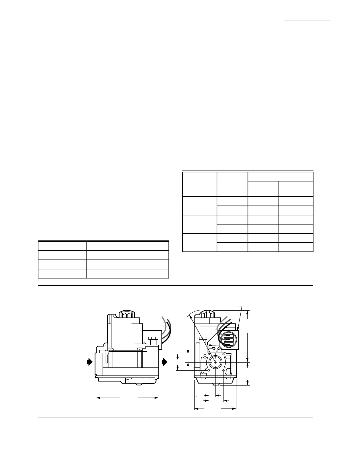
Fig. 1—Dimensions in in. [mm] of VR4204/VR8204 Combination Gas Control.
CONDUIT COVER (VR4204 ONLY)
3-5/8 [91]
SWING
RADIUS
1
[13]
2
1 [25]
1
1
4 [104]
8
[13]
2
1 [25]
11
2 [69]
16
3 68-0047—2
3
[89]
1
[28]
M9063
1
2
1
8

VR8204; VR4204
INSTALLATION
Installation
WHEN INSTALLING THIS PRODUCT…
1. Read these instructions carefully. Failure to follow
them could damage the product or cause a hazardous condition.
2. Check the ratings given in the instructions and on the
product to make sure the product is suitable for your
application.
3. Installer must be a trained, experienced service technician.
4. After installation is complete, check out product
operation as provided in these instructions.
WARNING
!
FIRE OR EXPLOSION HAZARD
CAN CAUSE PROPERTY DAMAGE,
SEVERE INJURY, OR DEATH.
Follow these warnings exactly:
1. Disconnect power supply before wiring to prevent electrical shock or equipment damage.
2. To avoid dangerous accumulation of fuel gas,
turn off gas supply at the appliance service
valve before starting installation, and perform
Gas Leak Test after completion of installation.
3. Do not bend pilot tubing at gas control or pilot
burner after compression fitting has been tightened, or gas leakage at the connection may
result.
4. Always install sediment trap in gas supply line
to prevent contamination of gas control.
5. Do not force the gas control knob. Use only
your hand to turn the gas control knob. Never
use any tools. If the gas control knob will not
operate by hand, the gas control should be
replaced by a qualified service technician. Force
or attempted repair may result in fire or explosion.
CAUTION
!
Never apply a jumper across or short the valve
coil terminals. This may burn out the heat anticipator in the thermostat or damage the electronic
intermittent pilot (IP) module.
IMPORTANT: These gas controls are shipped with pro-
tective seals over inlet and outlet tappings. Do not
remove seals until ready to connect piping.
Follow the appliance manufacturer instructions if available; otherwise, use the instructions provided on the following pages.
CONVERTING BETWEEN NATURAL AND LP GAS
WARNING
!
FIRE OR EXPLOSION HAZARD
CAN CAUSE PROPERTY DAMAGE,
SEVERE INJURY, OR DEATH.
1. Do not use a gas control set for natural gas on
an LP gas system or a gas control set for LP gas
on a natural gas system.
2. When making conversion, main pilot burner
orifices must be changed to meet appliance
manufacturer specifications.
Refer to appliance manufacturer instructions for orifice
specifications and changeover procedure. Gas controls are
factory-set for natural (and manufactured) or LP gas. Do
not attempt to use a control set for natural (manufactured)
gas on LP gas, or a control set for LP on natural (manufactured) gas.
Gas controls with standard or slow opening regulators
can be converted from one gas to the other with a conversion kit (ordered separately). Order part no. 393691 to
convert from natural (manufactured) to LP gas; order part
no. 394588 to convert from LP to natural (manufactured)
gas. Controls with step-opening regulators cannot be converted.
INSTALL ADAPTERS TO CONTROL
If adapters are to be installed on the gas control, mount
them as follows:
Flanges:
1. Choose the appropriate flange for your application.
2. Remove seal over control inlet or outlet.
3. Assure that the O-ring is fitted into the groove of the
flange. If the O-ring is not attached or missing, do not use
the flange.
4. With O-ring facing the control, align the screw holes
on the control with the holes in the flange. Insert and tighten
the screws provided with the flange. See Fig. 2. Tighten the
screws to 25 inch-pounds of torque to provide a gas-tight
seal.
Bushings:
1. Remove seal over control inlet or outlet.
2. Apply moderate amount of good quality pipe compound to bushing, leaving two end threads bare. On LP
installations, use compound resistant to LP gas. Do not use
Teflon tape.
3. Insert bushing in control and thread pipe carefully
into bushing until tight.
Complete installation below for piping, installing control, connecting pilot tubing and wiring. Make certain the
leak test you perform on the control after completing the
installation includes leak testing the adapters and screws. If
you use a wrench on the valve after flanges are installed,
use the wrench only on the flange, not on the control. See
Fig. 6.
68-0047—2 4

VR8204; VR4204
INSTALLATION
USING ADAPTERS TO SOLVE SWING RADIUS
PROBLEMS
In some field service applications, it is difficult or impossible to thread the control onto the gas supply pipe
because of space limitations. Usually this problem can be
resolved by using an adapter. The adapter is installed on the
end of the supply pipe in place of the gas control, following
the same precautions and instructions that are used for
installing the gas control. After the adapter is installed, the
gas control is attached to the adapter as outlined above.
Note that the use of an adapter increases the overall length
of the gas control.
Fig. 2—Fasten flange to control with 25 inch-
pounds torque.
6/32 INCH ROUND
SCREWS (1)
CONDUIT
COVER,
VR4204
ONLY
M9050
PIPED
GAS
SUPPLY
3 INCHES
[76]
MINIMUM
1
GAS
CONTROL
M3077
VALVE OUTLET
FLANGE
9/64 INCH HEX SCREWS (4)
DO NOT OVERTIGHTEN SCREWS. TIGHTEN TO
1
25 INCH-POUNDS.
Fig. 3—Sediment trap installation.
DROP
DROP
PIPED
GAS
SUPPLY
2
TUBING
GAS
SUPPLY
2
GAS
CONTROL
GAS
CONTROL
RISER
2
HORIZONTAL
3 INCHES
[76]
MINIMUM
HORIZONTAL
1
RISER
3 INCHES
[76]
MINIMUM
ALL BENDS IN METALLIC TUBING SHOULD BE SMOOTH.
1
CAUTION: SHUT OFF THE MAIN GAS SUPPLY BEFORE REMOVING
2
END CAP TO PREVENT GAS FROM FILLING THE WORK AREA. TEST
FOR GAS LEAKAGE WHEN INSTALLATION IS COMPLETE.
LOCATION
The combination gas control is mounted in the appliance vestibule on the gas manifold. If this is a replacement
application, mount the gas control in the same location as
the old control.
Locate the combination gas control where it cannot be
affected by steam cleaning, high humidity, or dripping
water, corrosive chemicals, dust or grease accumulation or
excessive heat. To assure proper operation, follow these
guidelines:
• Locate gas control in a well-ventilated area.
• Mount gas control high enough above the cabinet
bottom to avoid exposure to flooding or splashing
water.
• Assure the ambient temperature does not exceed the
ambient temperature ratings for each component.
• Cover gas control if appliance is cleaned with water,
steam, or chemicals or to avoid dust and grease
accumulation.
• Avoid locating gas control where exposure to corrosive chemical fumes or dripping water are likely.
Install Piping To Gas Control
All piping must comply with local codes and ordinances
or with the National Fuel Gas Code (ANSI Z223.1 NFPA
No. 54), whichever applies. Tubing installation must comply with approved standards and practices.
1. Use new, properly reamed pipe free from chips. If
tubing is used, make sure the ends are square, deburred and
clean. All tubing bends must be smooth and without deformation.
2. Run pipe or tubing to the control. If tubing is used,
obtain a tube-to-pipe coupling to connect the tubing to the
control.
3. Install sediment trap in the supply line to the gas
control. See Fig. 3.
Install Control
1. This control can be mounted 0-90 degrees, in any
direction, including vertically, from the upright position of
the gas control knob.
2. Mount the control so gas flow is in the direction of
the arrow on the bottom of the control.
3. Thread pipe into control or adapter. Do not thread
pipe too far. Valve distortion or malfunction may result if
the pipe is inserted too deeply. Refer to Table 4.
TABLE 4—NPT PIPE THREAD LENGTH IN in.
Pipe
Size
Thread Pipe
This Amount
Maximum Depth Pipe Can
Be Inserted Into Control
3/8 9/16 3/8
1/2 3/4 1 /2
3/4 13/16 3/4
4. Apply a moderate amount of good quality pipe compound (do not use Teflon tape) to pipe only, leaving two
end threads bare. On LP installations, use compound resistant to LP gas.
5 68-0047—2
 Loading...