

APPLICATION
TheVR6200H ContinuousPilot CombinationGasControl
is used in gas-fired appliances from 20 to 200 cfh natural
gas capacity. It includes safety shutoff a manual valve, two
automatic operators, a pressure regulator, a pilot filter, l/4
in. quick-connect convenience terminals, and an EC0
connector with two 114 in. quickconnect convenience terminals.
The VR6200H operates at 24V/60 Hz and has an
ambient temperature range of O0 F to 175” F [-I 6” C to 78’
C]. The thermostat heat anticipator setting is 0.5A.
Angle and straight adapters are available for 316. 112,
and 3/4 in. pipe. Refer to Table 1 for adapter part numbers.
Flange kits include one flange with attached O-ring, four
mounting screws, a 9164 in. hex wrench, and instruction
sheet.
The VR6200H is factory-set for natural gas. Do not
attempt to use VR6200H on LP gas. To convert VR6200H
from naturalgasto LPgas,followinstructionsinLPgasconversion kit.
TABLE l-FLANGE PART NUMBERS.
INLET/ LESS
OUTLET FLANGE
PIPE SIZE TYPE WRENCH WRENCH
310 in. NPT Straight 393690-I
l/2 in. NPT Straight 393690.6
314 in. NPT Straight 393690-4
a Elbow (angle) flanges cannot provide right hand inlet
when the EC0 connector is used.
NOTE: Flange Kits include one flange with attached
O-ring and four mounting screws.
AMERICAN GAS ASSOCIATION DESIGN CERTIFICATE:
P-70-42A.
CANADIAN GAS ASSOCIATION DESIGN CERTIFICATE:
1029~CC-6395 series.
AUSTRALIAN GAS ASSOCIATION CERTIFICATE: 4214.
Elbow” 393690-2 393690-I 2
Elbow 393690-3 393690-13
Elbow’ 393690-5 393690-15
PART NO. PART NO.
HEX
WITH
HEX
393690-I 1
393690-I 6
393690-14
INSTALLATION
WHEN INSTALLING THIS PRODUCT...
I, Read these instructions carefully. Failure to follow
them could damage the product or cause a hazardous
condition.
2. Check the ratings given in the instructions and on the
product to make sure the product is suitable for your
application.
3. Installer must be a trained, experienced service technician.
4. After installation is complete, check out product operation as provided in these instructions,
FIRE OR EXPLOSION HAZARD
CAN CAUSE PROPERTY DAMAGE, SEVERE
INJURY OR DEATH.
Follow these warnings exactly.
1. Disconnect oower SUDDIV before Wirha to
prevent electrical shot% or equipment iamage.
2. To avold dangerousaccumulatlon of fuel gas,
turn off gas supply at the appliance service
valve before starting installation, and perform
Gas LeakTest after completion of Installation.
3. Do not attempt to use a control set for natural
(manufactured) gason LP gas, or a control set
for LP on natural gas.
4. Do not bend pilot tubing at gas control or pilot
burner after compresslon nut has been tightened, or gas leakage at the connection may
result.
5. Always Install sediment trap in gas supply line
to prevent contamination of gas control.
6. Do not force the gas control knob. Use only
your hand to push down the reset button or
turn the gascontrol knob. Never use any tools.
If the knob or reset button will not operate by
hand, the control should be replaced by a
qualifledservketechnlclan.Forceorattempted
reoalr mav result In fire or explosion.
Never apply a jumper across or short the valve coil
terminals, This may burn out the heat anticipator in
the thermostat.
These gas controls are shipped with protective seals
over inlet and outlet tappings. Do not remove seals
until ready to connect piping.
Followthe appliance manufacturer’s instructions if avail-
able; otherwise, use the instructions provided below.
INSTALL ADAPTERS TO CONTROL
tf adapters are installed on the gas control, mount them
as follows:
Flanges:
I, Choose the appropriate flange for your application.
NOTE: A right angle inlet flange cannot be used with EC0
connected.
2. Remove seal over control inlet or outlet.
3. Check to ensure that the O-ring is fitted in the groove
of flange. ff the O-ring is not attached or is missing, do not
use the flange.
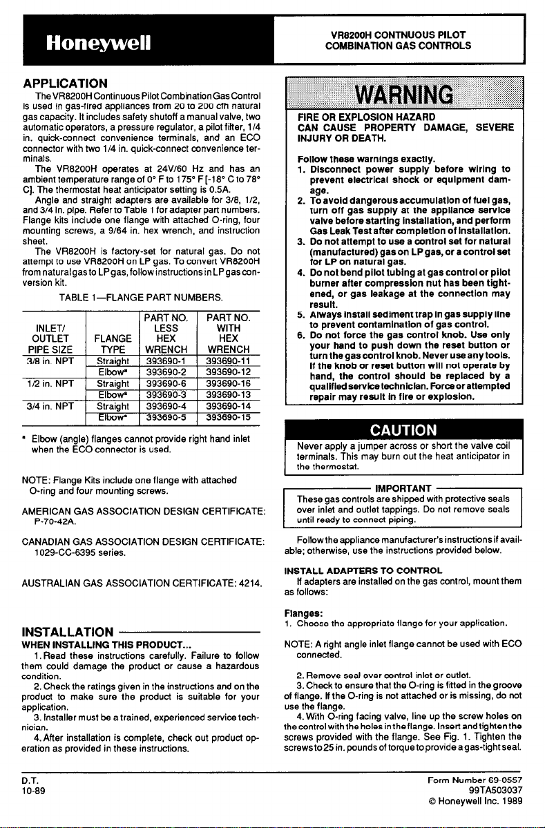
4. With O-ring facing valve, line up the screw holes on
thecontrolwiththe holesintheflange. lnsertandtightenthe
screws provided with the flange. See Fig. I. Tighten the
screwsto in. poundsof torque toprovideagas-tight seal.
IMPORTANT I
D.T.
1 O-89
Form Number 69-0557
99TA503037
0 Honeywell Inc. 1989
Bushings:
1. Remove seal over control inlet or outlet.
2. Apply moderate amount of good quality pipe compound to bushing, leaving two end threads bare. On LP
installation, usecompound resistantto LPgas. DoNOTuse
Teflon tape.
3. Insert bushing in control and thread pipe carefully into
bushing until tight.
Complete instructions below for piping, installing control, connecting pilottubing, thermocouple and wiring. Make
certain the leak test you perform on the control after
completing the installation includes leak testing the adapters and screws. ff you use a wrench on the valve after
flanges are installed, usethe wrench onlyon theflange, not
the control.
I I ,..I*
lg. l-Fasten flange to valve firmly, but do not over-
tighten ecrews.
LOCATfON
Do not locate the combination gas control where it may
be affected by steam cleaning, high humidity, or dripping
water, corrosive chemicals, dust or grease accumulation,
or excessive heat. To ensure proper operation, follow
these guidelines.
. Locate in a well ventilated area.
* Mount high enough above the cabinet bottom to
avoid exposure to flooding or splashing water.
- Ensure the ambient temperature does not exceed
the ambient temperature ratings for each component.
* Cover gas control if appliance is cleaned with water,
steam, or chemicals or to avoid dust and grease
accumulation.
* Avoid locating where exposure to corrosive chemi-
cal fumes or dripping water are likely.
Mount the combination gas control in the appliance
vestibule on the gas manifold. ff this is a replacement application, mount the new control in the same location as
the old control.
Install Piping to Control
All piping must comply with local codes and ordinances
or with the National Fuel Gas Code (ANSI 2223.1 NFPA
No. 54) whichever applies. Tubing installation must comply with approved standards and practices.
1. Use new, properly reamed pipe free from chips. ff
tubing is used, make sure the ends are square, deburred
and clean. All tubing bends must be smooth and without
deformation.
2. Run pipe or tubing to the control. ff tubing is used,
obtain a tube-to-pipe coupling to connect the tubing to the
control.
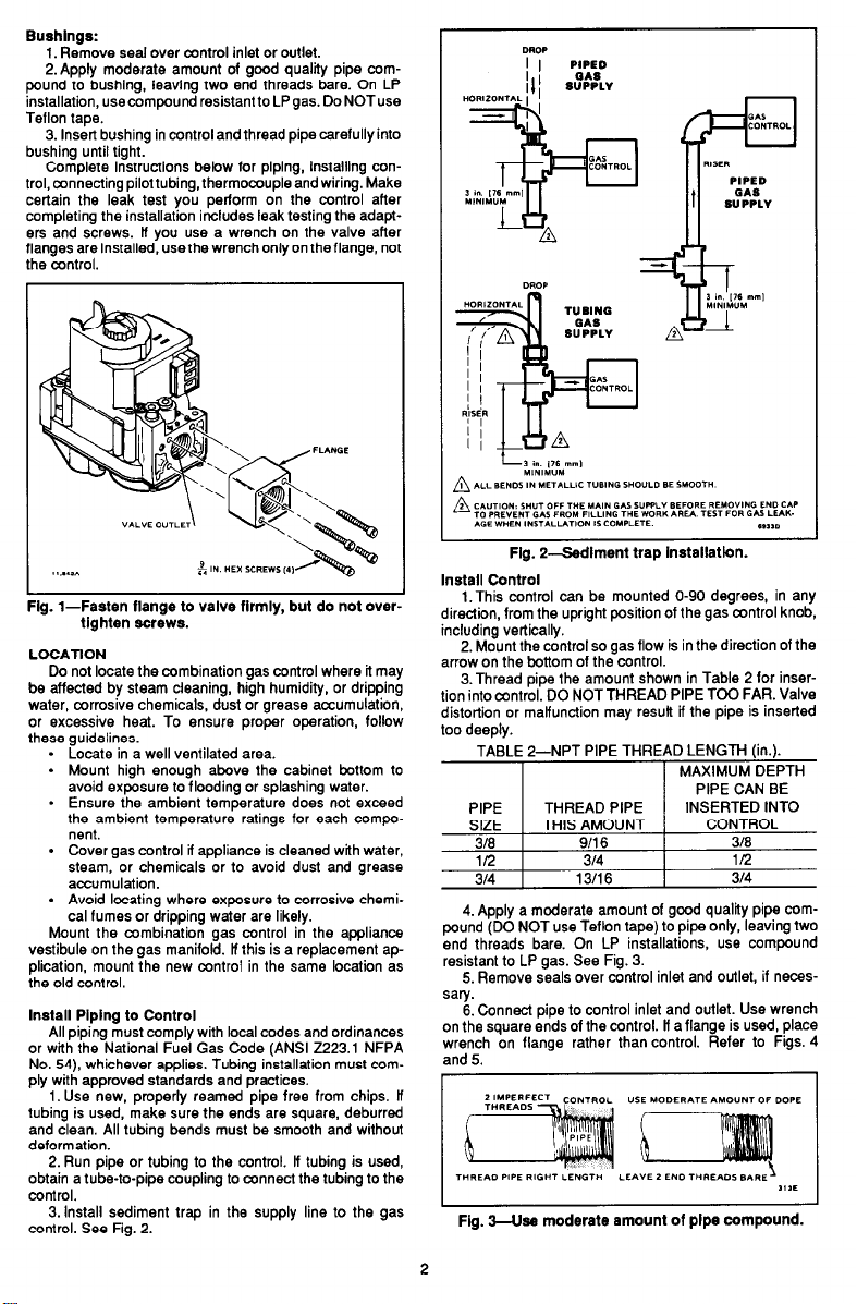
3.lnstall sediment trap in the supply line to the gas
control. See Fig. 2.
Flg. Zadlment trap installatfon.
Install Control
I
l.This control can be mounted O-90 degrees, in any
direction, from the upright position of the gas control knob,
including vertically.
2. Mount the control so gas flow is in the direction of the
arrow on the bottom of the control.
3.Thread pipe the amount shown in Table 2 for insertion into control. DO NOT THREAD PIPE TOO FAR. Valve
distortion or malfunction may result if the pipe is inserted
too deeply.
TABLE 2-NPT PIPE THREAD LENGTH (in.).
I
I
4. Apply a moderate amount of good quality pipe com-
pound (DO NOT use Teflon tape) to pipe only, leaving two
end threads bare. On LP installations, use compound
resistant to LP gas. See Fig. 3.
5. Remove seals over control inlet and outlet, if neces-
sary.
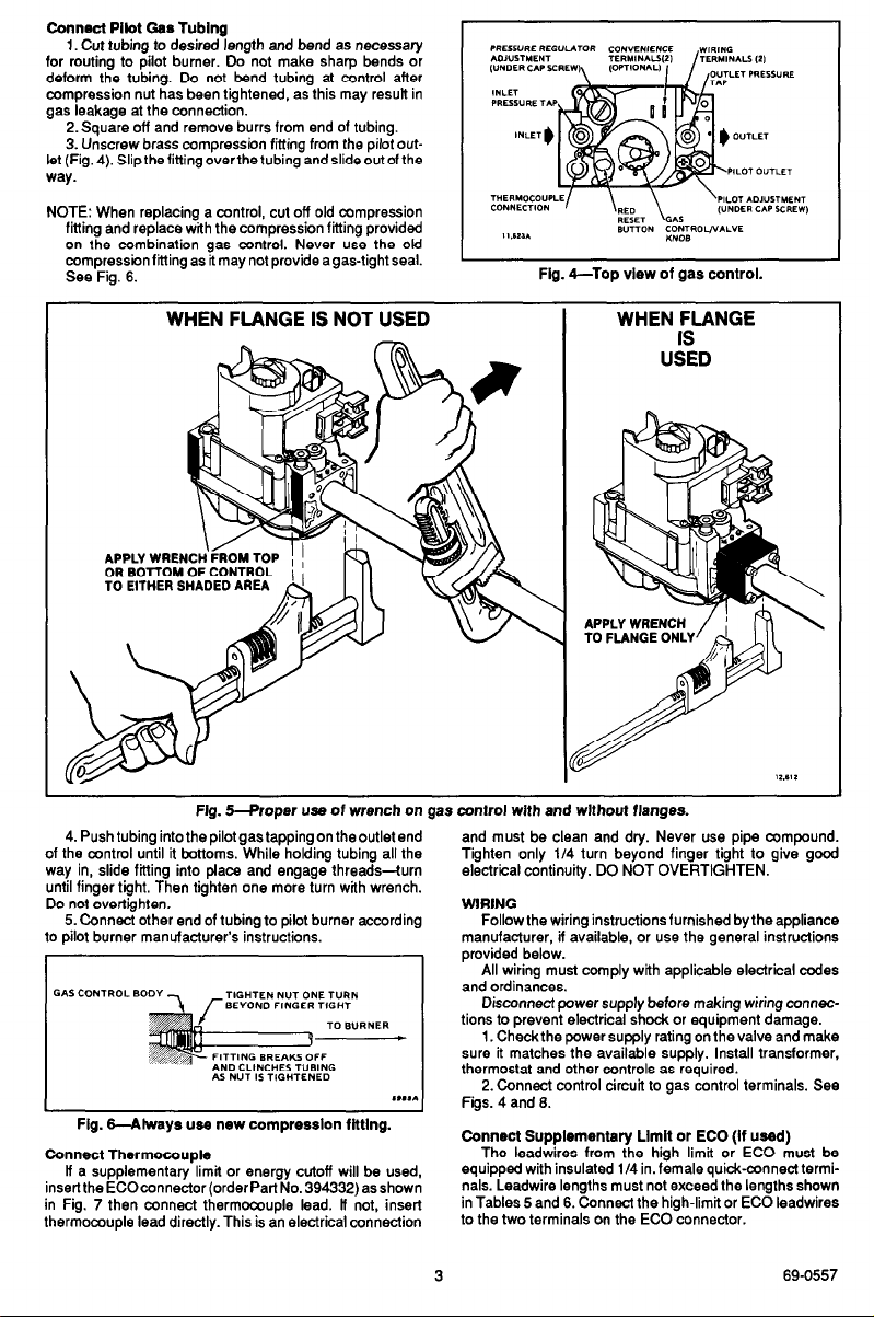
6. Connect pipe to control inlet and outlet. Use wrench
on the square ends of the control. ff a flange is used, place
wrench on flange rather than control. Refer to Figs. 4
and 5.
1 MAXIMUM DEPTH
1 PIPE CAN BE
I
Fig. 3-Use moderate amount of plpe compound.
2
Connect Pilot Gas Tubing
1. Cut tubing to desired length and bend as necessary
for routing to pilot burner. Do not make sharp bends or
deform the tubing. Do not bend tubing at control after
compression nut has been tightened, as this may result in
gas leakage at the connection.
2. Square off and remove burrs from end of tubing.
3. Unscrew brass compression fitting from the pilot out-
let (Fig.4). Slipthefittingoverthetubing andslideoutofthe
way.
NOTE: When replacing a control, cut off old compression
fitting and replace with the compression fitting provided
on the combination gas control. Never use the ofd
compression fitting as it may not provide a gas-tight seal.
See Fig. 6.
11.1211
Fig. ~-TOP view of gas control.
B”TTDN mTBRow*L”E
WHEN FLANGE IS NOT USED
APPLY WRENC
OR BOTTOM 0
TO EITHER SHADED AREA
Fig. S-F’roper usa of wrench on gas control with and without flanges.
4. Push tubing into the pilot gas tapping on the outlet end
of the control until it bottoms. While holding tubing all the
way in, slide fitting into place and engage threads--turn
until finger tight. Then tighten one more turn with wrench.
Do not overtlghten.
5. Connect other end of tubing to pilot burner according
to pilot burner manufacturer’s instructions.
,**,*
Fig. GAlways use new compression fitting.
Connect Thermocouple
ff a supplementary limit or energy cutoff will be used,
inserttheECOconnector(orderPartNo.394332)asshown
in Fig. 7 then connect thermocouple lead. ff not, insert
thermocouple lead directly. This is an electrical connection
WHEN FLANGE
“k:D
and must be clean and dry. Never use pipe compound.
Tighten only 114 turn beyond finger tight to give good
electriial continuity. DO NOT OVERTIGHTEN.
WRING
Follow the wiring instructions furnished by the appliance
manufacturer, if available, or use the general instructions
provided below.
All wiring must comply with applicable electrical codes
and ordinances.
Disconnect power supply before making wiring wnnec-
tions to prevent electrical shock or equipment damage.
1. Check the power supply rating on the valve and make
sure it matches the available supply. Install transformer,
thermostat and other controls as required.
2. Connect control circuit to gas control terminals. See
Figs. 4 and 6.
Connect Supplementary Limit or EC0 (If used)
The leadwires from the high limit or EC0 must be
equipped with insulated l/4 in. female quick-connect termi-
nals. Leadwire lengths must not exceed the lengths shown
in Tables 5 and 6. Connect the high-limit or EC0 leadwires
to the two terminals on the EC0 connector.
3 69-0557
 Loading...