

Page 1
63-2720-02
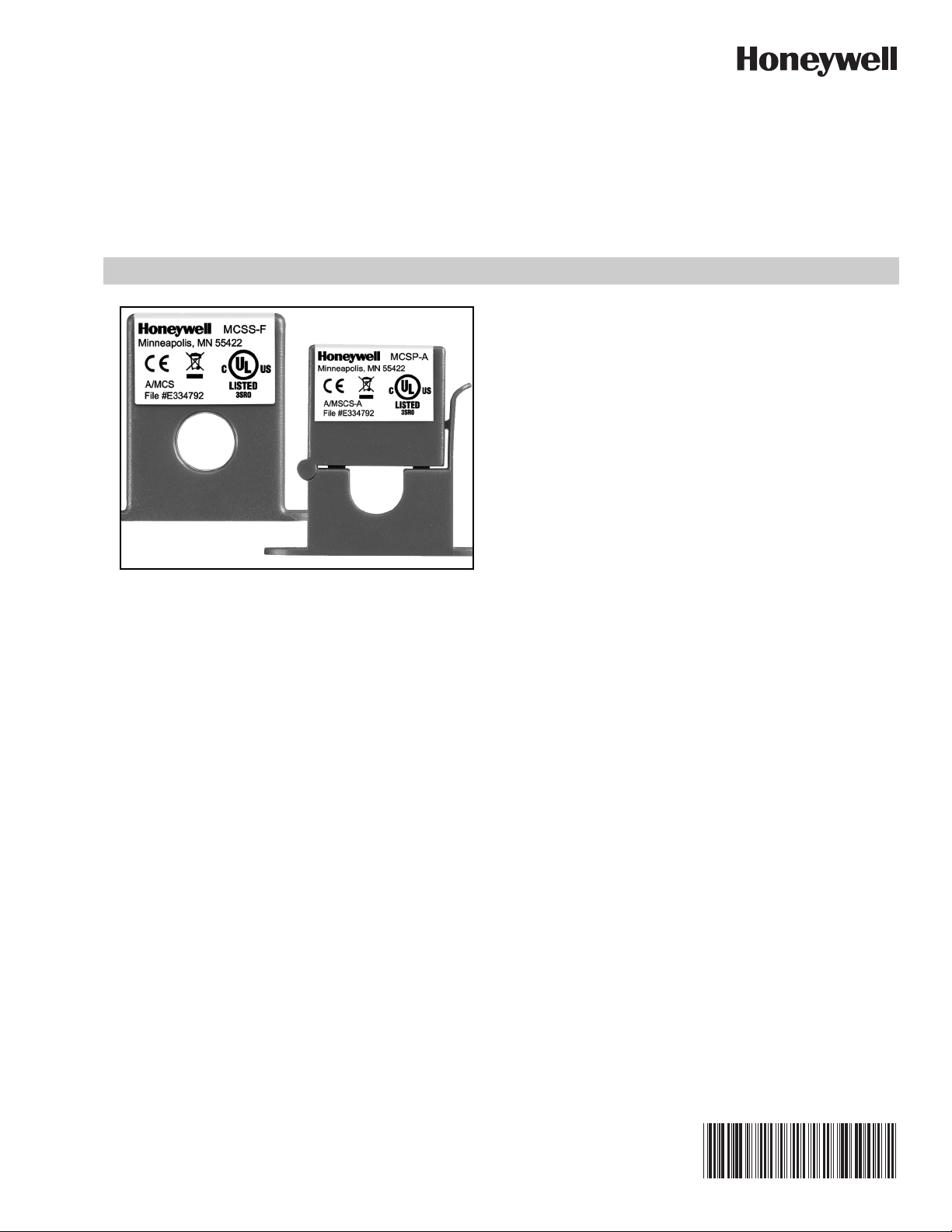
MCSS/MCSP Current Switches
SPECIFICATION DATA
The MCSS and MCSP Series are covered by a five (5) year
limited warranty.
SPECIFICATIONS
Sensor Power: Induced from monitored conductor
Amperage Rating:
MCSS-F: 0.20 to 150 Amps
MCSP-F: 0.55 to 150 Amps
MCSS-A: 0.32 to 150 Amps continuous
MCSP-A: 0.70 to 150 Amps continuous
Max. Sensing Current Voltage: 600 VAC
Isolation Voltage: 2,200 VAC
Output Rating:
APPLICATION
The Honeywell MCSS and MCSP series current switches are
miniature “Go/No Go” current status switches designed to
provide status information on AC current supplied equipment.
The output of these switches uses a N/O solid-state switch
(more reliable than a relay) and is non-polarity sensitive.
The MCSS series is an excellent option for new installations
where the conductors can be run through the solid-core
housing before connecting the wires. The MCSP series are
ideal for retrofit applications, since their split-core design
allows them to be opened and clamped around the existing
wires without disconnecting the current being monitored. Both
of these units do not need power supplied to them as they
induce the current from the conductors being monitored.
The MCSS series has a fixed trip point of below 0.20 A while
the MCSP series has a fixed trip point of below 0.55 A. When
the current in the conductor exceeds this threshold, the sensor
will be “Closed.” The sensor will indicate “Open” when the
current is interrupted or falls to 0 A.
MCSS-F: 0.5 A Continuous, 36 VAC/VDC
MCSP-F: 0.5 A Continuous, 36 VAC/VDC
MCSS-A: 1.0 A Continuous, 36 VAC/VDC
MCSP-A: 1.0 A Continuous, 36 VAC/VDC
Status LED Indication (MCSS-A/MCSP-A models only):
Red LED: Above Trip Point
Blue LED: Under Trip Point
NOTE: Do NOT use the LEDs to indicate whether the sen-
sors have power applied to them.
Operating Frequency: 50 Hz, 60 Hz
Isolation Voltage: 2,200 VAC
Aperture (Hole) Size:
MCSS: 0.55” dia., up to 1 AWG cables
MCSP: 0.53” dia., up to 1 AWG cables
Trip Point :
MCSS-F: Fixed @ below 0.20 A
MCSP-F: Fixed @ below 0.55 A
The adjustable switches, MCSS-A and MCSP-A , include two
Status LED indicators that will indicate three states: tripped
on, current present but below trip point, and current off or
below the low end of the adjustable trip point range. Also
these adjustable current switches can be used to monitor any
change in AC current. A change in current may indicate motor
failure, belt loss/slippage, or mechanical failure. Any time one
of these events occurs, the current can significantly decrease,
thus tripping the current switch and immediately notifying the
Building Management System of the failure or problem.
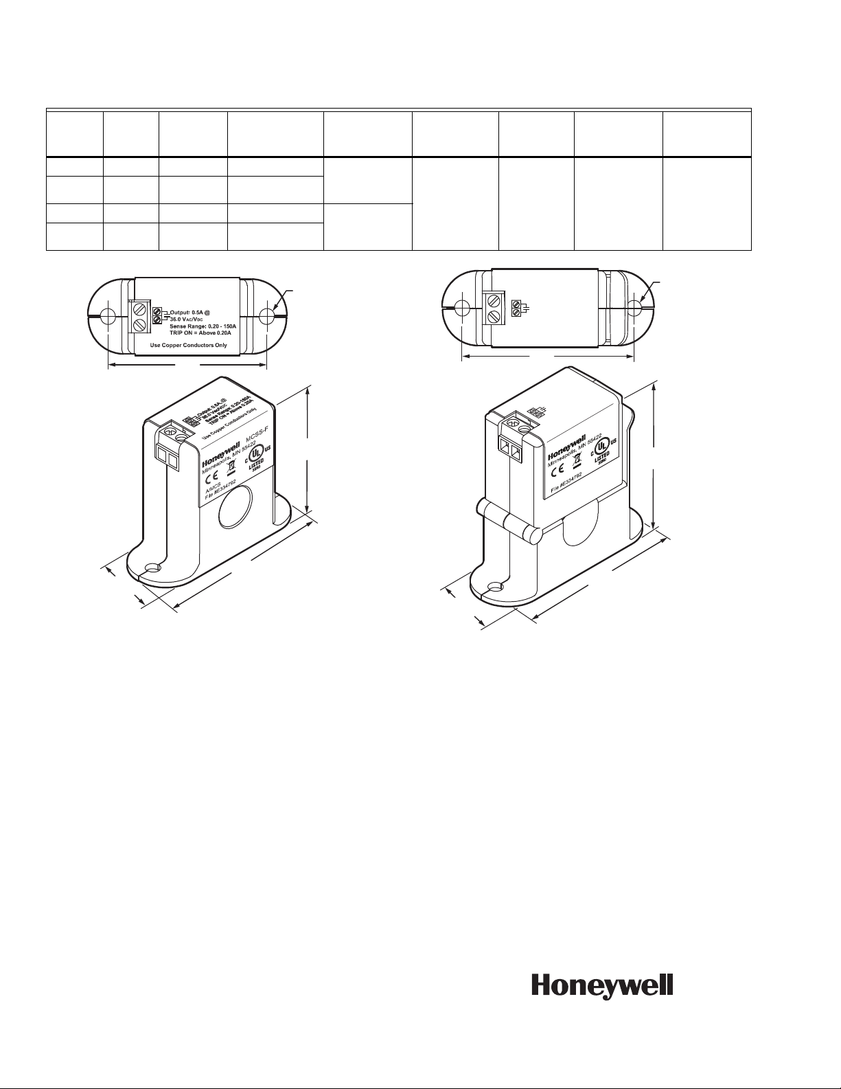
Dimensions ( L x W x H ):
MCSS: 2.50" x 1.96" x 0.95"
MCSP: 2.65" x 2.35" x 0.95"
Operating Temperature Range: -30 to 60 ºC (-22 to 140 ºF)
Operating Humidity Range: 0 to 95% RH, non-condensing
Page 2
MCSS/MCSP CURRENT SWITCHES
2 (51)
[2] Ø 3/16 (5)
2-1/2 (64)
M33393
1-63/64
(51)
15/16
(24)
Table 1. Current switch operating specifications.
Model
Core
Typ e
Switch
Type Trip Point
Output
Switch Rating
MCSS-F Solid Fixed < 0.20 Amps 0.50 Amp
MCSP-F Split Fixed < 0.55 Amps
@ 36 VAC/
VDC
MCSS-A Solid Adjustable 0.32 - 150 Amps 1.00 Amp
MCSP-A Split Adjustable 0.70 - 150 Amps
@ 36 VAC/
VDC
Max. Sensing
Current
Voltag e
Max.
Continuous
Current
Max. Current
for
6 seconds
Max. Current
1 second
600 VAC 158 Amps 240 Amps 600 Amps
[2] Ø 3/16 (5)
Output: 0.5A@
36.0 V
AC/VDC
Sense Range: 0.55-150A
TRIP ON = Above 0.55A
Use Copper Conductors Only
2 (51)
DC
/V
AC
Output: 0.5A@
36.0 V
Sense Range: 0.55-150A
TRIP ON = Above 0.55A
Use Copper Conductors Only
MCSP-F
2-23/64
(60)
A/MSCS
for
2-41/64
(67)
15/16
Fig. 1. Dimensions in inches (mm) of the solid core
models MCSS-F and MCSS-A.
(24)
Fig. 2. Dimensions in inches (mm) of the split core
models MCSP-F and MCSP-A.
M33394
By using this Honeywell literature, you agree that Honeywell will have no liability for any damages arising out of your use or modification to,
the literature. You will defend and indemnify Honeywell, its affiliates and subsidiaries, from and against any liability, cost, or damages,
including attorneys’ fees, arising out of, or resulting from, any modification to the literature by you.
Automation and Control Solutions
Honeywell International Inc.
® U.S. Registered Trademark
© 2012 Honeywell International Inc.
63-2720—02 M.S. 07-12
Printed in United States
 Loading...