

Honeywell VQ400, VQ420, VQ440, VQ425, VQ450 Product Handbook

UNIVERSAL GAS VALVES
VQ400 Series
CLASS “A” COMBINATIONVALVES
PRODUCT HANDBOOK
APPLICATION
The VQ400 Series class “A” safety combination valves are
used for control and regulationofgaseous fluids in gas power
burners, atmospheric gas boilers, melting furnaces,
incinerators and othergasconsuming appliances.
These combination valves are available intwoversions:
model VQ420/25 (pipe sizes3/4” and 1”)
and model VQ440/50(pipesizes 1 1/2” and 2”).
The 1 1/4” connection is obtained by using a DN32 flange kit
on a VQ440 body.
The features and specificationsofboth models are identical
(unless specified otherwise).
model VQ440/50
model VQ420/25
Contents
General
Description 2.......................................
Features 3.........................................
Technical
Specifications 4 -- 5.................................
Performance characteristics 6........................
Capacity curves 7...................................
Dimensional drawings 8 -- 9.........................
Installation and Operation
Installation 10......................................
Adjustments and finalcheckout 11 -- 12...............
Construction and workingprinciples 13................
Various
Standards and approvals 14..........................
Ordering information 15 -- 16.........................
Standard configurations 17 -- 26......................
Replacement parts and accessories 27................
Subject to change withoutnotice. Printed in the Netherlands.
EN2R--9018 9704R1--NE

DESCRIPTION
The VQ400 Series combination valves are suitable for the
controlof gaseous fluidsin gas consuming appliances
according to international standards.
The VQ400 Series combination valves meet the class “A”
specification according EN161.
The VQ400 Series combination valves have straight flanged
pipe connection from 3/4” up to 2”.
The VQ400 Series combination valves are standard equipped
with two main valves V1 and V2. Safety valve V1 is always
fast opening/closing. The second valve (V2) can be either fast
(= with flow regulation) or slow (= with flow regulation and
adjustable opening).
At the main body (4) flange connections are provided to
mount either an:
• internalby--pass valve to achieve high--low flame control
• internalor external pilot valve
• vent valve
• pressure switch (Min. or Max.)
• Valve Proving System (VPS) + pressure switch.
These accessories can be mounted on various positions of
the main body of the VQ400.
2
EN2R--9018 9704R1- -NE

FEATURES
• Class “A” safety combination valve for control of
gaseous fluids in gas consuming appliances in
accordance with international standards.
• Main body with two gas valves with single seat.
• Internalby--pass valve to achieve high--low flame
control.
• internalor external pilot valve.
• Ventvalve.
• Options for mounting flanged minimum and maximum
pressure switches.
• ValveProving System (VPS).
• Closing time: < 1 second.
• Coils field replaceable.
• Coils suitable for permanent energization.
• Fine mesh screen between inlet flange and main body.
• Various pressure tap points at main body available,
when no additional valves or pressure switches are
used.
• Second main valve, either with adjustable flow
regulator(fast), or characterizedopening mechanism
(slow) with adjustable maximum flow rate and step
pressure.
• Rectifier board with LEDs (VQ440/50 only) to indicate
energization of coil
• Rectifier boards field replaceable.
• Plug connector according to DIN 43650: standard for
VQ440/50, optional for VQ420/25.
• PG11 cable strain relief standard at VQ420/25.
• Optional mounting of Closed Position Indication
switch (CPI) at bottom of safety valve V1.
3
EN2R--9018 9704R1- -NE

SPECIFICATIONS
The specifications described in this chapter are related to the
main gas valve, by--pass valve and pilot valve (see also
Performancecharacteristics on page 6.).
Models
VQ420/25 (DN20 and DN25)
VQ440/50 (DN40 and DN50)
NOTE: DN32 connection is obtained with a flange kit on
The main gas volume is adjustable at 2
The startflow is adjustable at slow open 2
Dimensions
See dimensionaldrawings and table on page 8 and 9.
Pipe sizes
Main body
1 1/4”,1 1 /2” and 2”.
Pilot valve and vent valve
(all internal pipe thread according to ISO 7--1)
Capacity
Main body
VQ440 body.
:Inletand outletstraight flange connection 3/4”, 1”,
: outlet 3/4” thread.
: see capacity curves on page 7.
Pilot valve and vent valve on VQ400 DN20 ... 50
By--pass on VQ400 DN20 ... 40
By--pass on VQ400 DN50:
(see capacity curves VE4000 Series product handbook)
Maximum operating pressure
200 or 360 mbar, depending on the model
Connections
• Pressure taps at inlet and outlet flanges.
•
Optional:
Indication switch (CPI) at bottom of safety valve V1.
At the main body (4) flange connections are provided to
mount either an:
• internalby--pass valve to achieve high--low flame control
• internalor external pilot valve
• vent valve
• pressure switches (Min. or Max.)
• Valve Proving System (VPS).
By--pass valve/high--low valve
Twostage valve 3/4” is used at VQ420/425/440 series valves.
Twostage valve 1” is used at VQ450 series valves.
Torsion and bendingstress
Pipe connections meet group 2 according to EN161
requirements.
Supplyvoltages
Line voltage: 220 ...240 Vac,50/60 Hz
Other voltages on request.
Electricalequipment
DC current coils with separated rectifierinside the cover.
1/4” plug connection for Closed Position
200 Vac, 50/60 Hz
100/110 Vac, 50/60 Hz
24 ...28 Vdc
: as VE4020
as VE4025
nd
main valve.
nd
main valve.
: as VE4020
Electricalconnections
VQ420/25: standard plug connection according PG11 on main
gas valves and additional valves.
Optional:
valves and additional valves.
VQ440/450: standard three pin plug connector (”DIN plug”) on
main gas valves.
Optional:
valves.
Ambienttemperaturerange
--15 ... 60 °C
Coilinsulation solenoid valves
Insulation material according class F.
Enclosure
IP 54
IP65 (optional, only for VQ420/25)
Bodymaterial
aluminium alloy die cast
Strainer
AISI 303 steel
Closingspring
AISI 302 steel
Valve plunger
Chrome plated Fe 360B steel sliding on anti--friction bearing.
Sealsand gaskets
Hydrocarbon resistant NBR rubber type.
Flangekits
There are two different series of kits available:
The firstseries of kits consist of: 1 flange with sealing plug,
1 O--rings and 4 screws.
The second series of kits consist of: 1 flange with sealing plug
or cast pressure tap, 1 strainer, 1 O--rings and 4 screws.
three pin plug connector (”DIN plug”) on main gas
three pin plug connector (”DIN plug”) on additional
O.S. number
KTCOMB20 3/4” with plug
KTCOMB25 1” with plug
KTCOMB32 11/4” intended for 440
KTCOMB40 11/2” with tap
KTCOMB50 2” with tap
O.S. number
KTCOMS20 3/4” with plug
KTCOMS25 1” with plug
KTCOMS32 11/4” intended for 440
KTCOMS40 11/2” with tap
KTCOMS50 2” with tap
Size (Rp) Remarks
body, with tap
Size (Rp) Remarks
body, with tap
4
EN2R--9018 9704R1- -NE
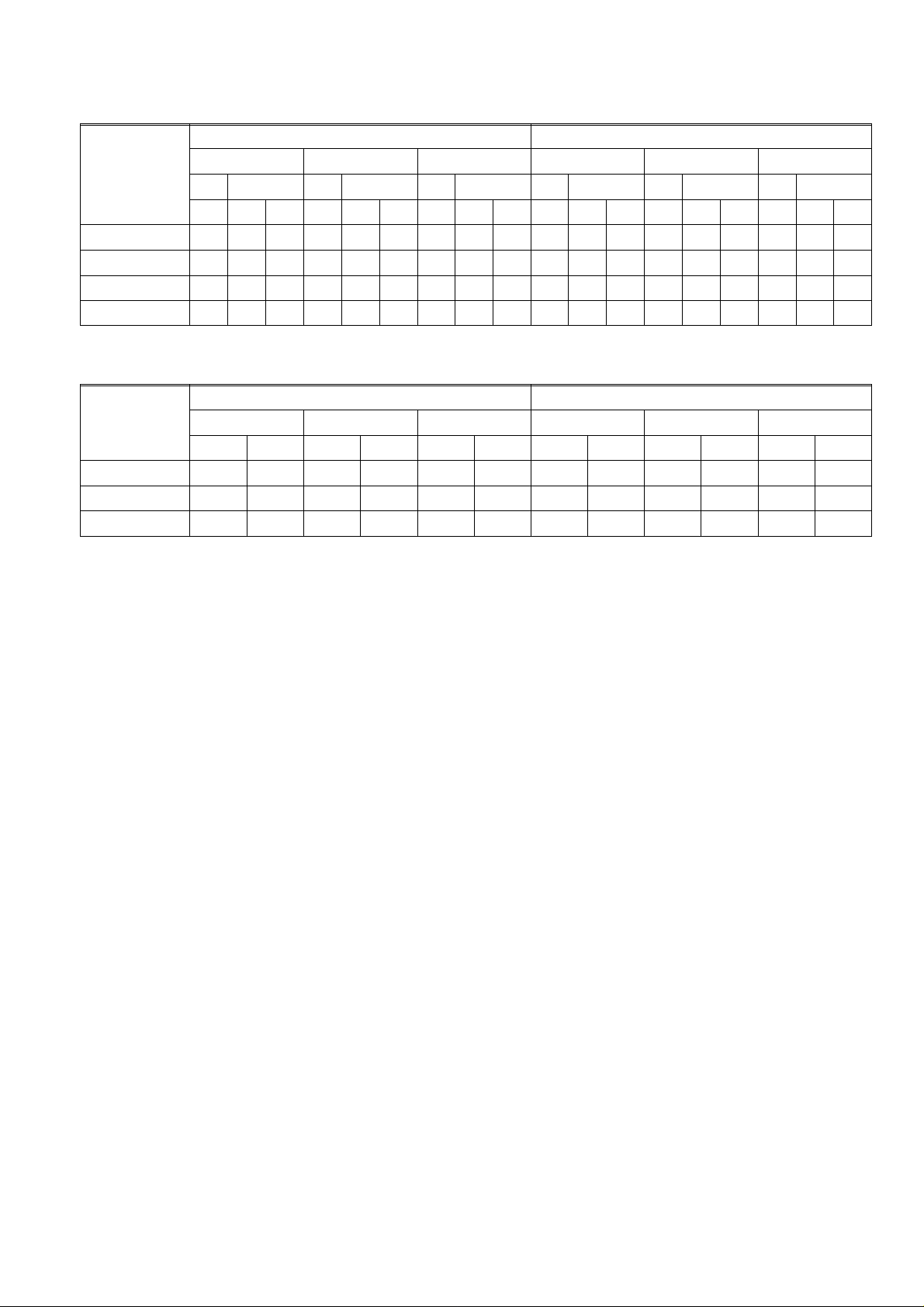
Table 1. Power consumption (W) main valve VQ400 Series
360 mbar 200 mbar
Model
220 ... 240 Vac 100/110Vac 24 ... 28 Vdc 220 ... 240 Vac 100/110 Vac 24 ... 28 Vdc
V1 V2 V1 V2 V1 V2 V1 V2 V1 V2 V1 V2
F S F S F S F S F S F S
VQ420Ax 14 14 14 14 14 14 17 17 17 14 14 14 14 14 14 17 17 17
VQ425Ax 20 20 20 18 18 18 24 24 24 20 20 20 18 18 18 24 24 24
VQ440Ax 41 41 41 48 48 48 64 64 64 40 40 40 47 47 47 67 67 67
VQ450Ax 60 60 60 65 65 65 67 67 67 41 41 41 48 48 48 64 64 64
Table 2. Power consumption (W) additional valves
Additional
valve
220 ... 240 Vac 100/110 Vac 24 ... 28 Vdc 220 ... 240 Vac 100/110 Vac 24 ... 28 Vac
360 mbar 200 mbar
3/4” 1” 3/4” 1” 3/4” 1” 3/4” 1” 3/4” 1” 3/4” 1”
by--pass valve 14 20 14 18 17 24 14 20 14 18 17 24
pilot valve 14 -- 14 -- 17 -- 14 -- 14 -- 17 --
vent valve 14 -- 14 -- 17 -- 14 -- 14 -- 17 --
5
EN2R--9018 9704R1- -NE

PERFORMANCE CHARACTERISTICS
Opening time
The firstvalve (V1) opens in less than 1 second.
The second valve (V2), by--pass valve (Vb) and pilot valve
(Vp) can be either a fast opening valve which opens in less
than 1 second or a characterized opening valve which is
adjustable from 1 up to 30 seconds, at rated capacity.
The opening characteristicis factory set at approximately 6
seconds at the following conditions:
− measured at 80 % of rated capacity
− 30mbar supply pressure
− nominal voltage
− 20
− 2,5 mbar pressure drop
− nostep pressure
Due to the influence of ambient temperature (--15 ... 60
the adjusted opening time of 6 seconds measured at 80% of
adjusted flow rate can vary
Closing time (V1, V2 , Vb and Vp)
Less than 1 second for all four valves.
E
C
E
C)
+
/--4 seconds.
Maximum workingfrequency
1 cycle per minute
Duty cycle
Coil suitable for permanent energization
Operational voltage range
The combinationgas valve willfunction satisfactorybetween
85% and 110% of the rated voltage.
Design life
Model
VQ420AA 600,000
VQ425AA 600,000
VQ440AA 300,000
VQ450AA 300,000
Number of Cycles
6
EN2R--9018 9704R1- -NE
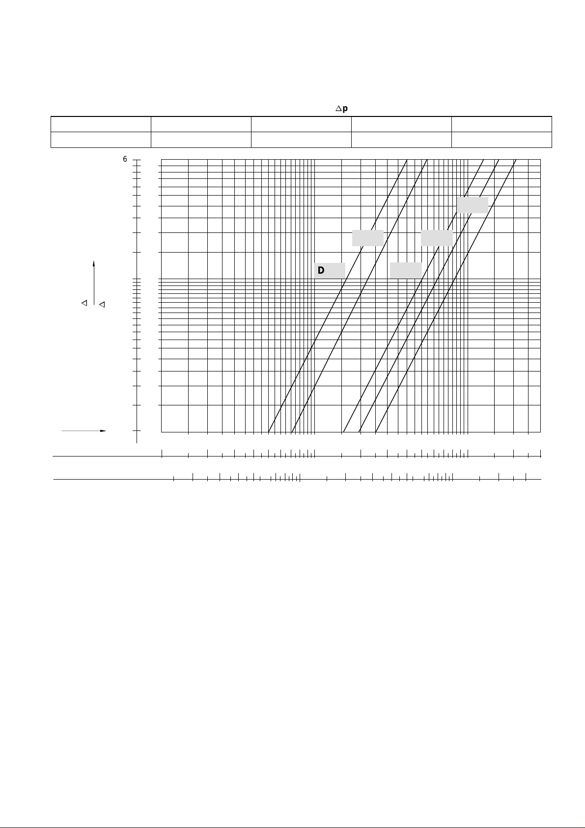
CAPACITY CURVES
Capacity curve combination gas valves
Table 1. Capacity in m3/hair atap=2,5mbar
3/4” DN20
8 11 25 31 40
6
60
5
50
40
4
30
3
20
2
10
1
p(kPa)
a
0.8
p (mbar)
a
0.6
0.5
0.4
0.3
8
6
5
4
3
1” DN25 1 1/4” DN32 1 1/2” DN40 2” DN50
DN20
DN25
DN50
DN40
DN32
Vn (m3/h)
Air dv=1
Methane dv 0.64
0.2
0.1
2
1
1234568
10 20 30 40 50 60 80 200 300
10865432
Fig. 1. Capacity curves for VQ400 Series class “A” combination valves
100
100 300200806050403020
7
EN2R--9018 9704R1- -NE

DIMENSIONAL DRAWINGS
C
HONEYWELL
A
BC
B
A
3/4”
D
H
H
D
62
188
151
E
Fig. 2. Overall dimensions VQ400 Series (shown 2ndvalve slow)
8
EN2R--9018 9704R1- -NE
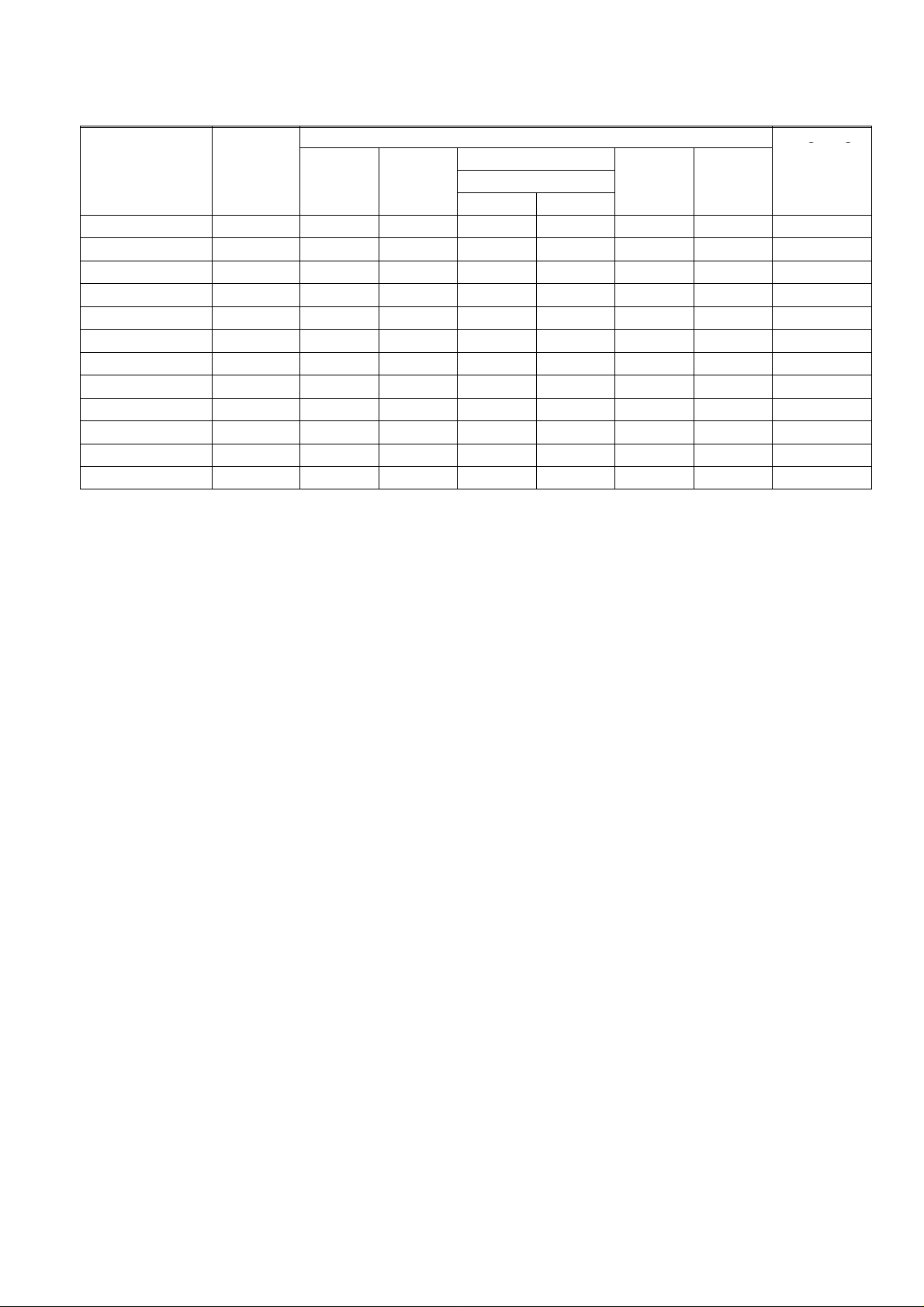
Table 2. Dimensions VQ400 Series (see also installation drawing).
g(g
)
Model Connect.
(inch)
A B
Overall Dimensions (mm)
C
D E
Weight (kg)
2ndmain valve
fast slow
VQ420Ax 3/4 204 42.5 111.5 157.5 60 108 3.5
VQ420Bx--Cx--Ex 3/4 204 42.5 112 157 60 177 4.8
VQ420Dx--Fx 3/4 204 42.5 112 157 60 247 6.1
VQ425Ax 1 204 42.5 135.5 181.5 64.5 108 5.0
VQ425Bx--Cx--Ex 1 204 42.5 136 181 64.5 177 6.3
VQ425Dx--Fx 1 204 42.5 136 181 64.5 247 7.6
VQ440Ax 11/2 297 62 174 228 63.5 119 10.7
VQ440Bx--Cx--Ex 11/2 297 62 174 228 63.5 209 11.9
VQ440Dx--Fx 11/2 297 62 174 174 63.5 300 13.5
VQ450Ax 2 297 62 174 (184) 228 (238) 63.5 119 12.1
VQ450Bx--Cx--Ex 2 297 62 174 (184) 228 (238) 63.5 209 14.1
VQ450Dx--Fx 2 297 62 174 (184) 228 (238) 63.5 300 16.4
(..)360 mbar versions
9
EN2R--9018 9704R1- -NE
 Loading...