

Honeywell VPX Installation Instructions Manual

Installation Instructions for the
MICRO SWITCH VPX Series
Valve Position Indicator for Hazardous Locations
Issue F
32312068
Multiple language versions of installation instructions and
other documents are available on Honeywell’s website. To
access:
1. Go to http://sensing.honeywell.com/hazardousareaswitches
2. Select the product’s instructions from the installation instruction section.
Installationsanweisungen und andere Dokumente stehen in
mehreren Sprachen auf der HoneywellWebsite zur Verfügung. So greifen Sie darauf zu:
1. Gehen Sie auf die Webseite http://sensing.honeywell.de/
hazardousareaswitches
2. Wählen Sie im Bereich “Installationsanweisungen” die zum
entsprechenden Produkt gehörenden Anweisungen aus.
Versiones de las instrucciones de instalación y otros documentos se encuentran disponibles en el sitio de internet de
Honeywell en múltiples idiomas. Para acceder:
1. Vaya a http://sensing.honeywell.com/hazardousareaswitches
2. Seleccione las instrucciones del producto en la sección de
instruccions de instalación.
Les instructions d’installation et d’autres documents
sont disponibles dans plusieurs langues sur le site Web
d’Honeywell. Procédure d’accès :
1. Accédez à la page http://sensing.honeywell.com/hazardousareaswitches
2. Sélectionnez les instructions relatives au produit qui vous
intéresse dans la section « Installation Instructions
mWARNING
PERSONAL INJURY
DO NOT USE these products as safety or emergency stop
devices or in any other application where failure of the
product could result in personal injury.
Failure to comply with these instructions could result in
death or serious injury.
mWARNING
IMPROPER CONDUIT THREAD USE
DO NOT USE any other conduit thread than the one
identified on the product. Verify that the mating threaded
fitting is identical with the conduit thread marked near the
conduit opening (see Figure 6).
Failure to comply with these instructions could result in
death or serious injury.
mWARNING
To maintain ATEX/IECEx protection methods, an Ex cable
gland or Ex conduit sealing device, rated Ex db IIC Gb
IP66, Ex tb IIIC Db IP66 shall be installed. For Intrinsically
Safe models, cable glands must have a minimum service
temperature of 80oC.
mWARNING
Enclosure contains aluminum. Care must be taken to avoid
hazard due to impact or friction
mWARNING
To reduce the risk of ignition in hazardous atmospheres,
conduit runs must have a sealing fitting connected within
18 inches of enclosure.
Sul sito Web di Honeywell sono disponibili istruzioni per
l’installazione in più lingue e altra documentazione. Per accedere:
1. Andare a http://sensing.honeywell.com/hazardousareaswitches
2. Selezionare le istruzioni per il prodotto nella sezione istruzioni
per l’installazione.
As versões em diversos idiomas das instruções de instalação
e outros documentos estão disponíveis no site da Honeywell.
Para acessar:
1. Vá para http://sensing.honeywell.com/hazardousareaswitches
2. Selecione as instruções do produto na seção de instruções de
instalação.
多语种安装指南和其他文档均可从霍尼韦尔的网站上获取。访问
网站:
1.前往 http://sensing.honeywell.com/hazardousareaswitches
2.从安装指南部分选择具体的产品指南。
На веб-сайте Honeywell имеются инструкции по установке
и другие документы на различных языках. Для доступа
к ним выполните следующие действия.
1. Перейдите по адресу http://sensing.honeywell.com/
hazardousareaswitches
2. Выберите инструкции для изделия в разделе инструкций
по установке.
mWARNING
Substitution of components may impair intrinsic safety.
mWARNING
OPENING PRODUCTS HAZARD
DO NOT OPEN these products when energized or in a
flammable gas atmosphere.
Failure to comply with these instructions could result in
death or serious injury.
mWARNING
RISK TO LIFE OR PROPERTY
Never use this product for an application involving serious
risk to life or property without ensuring that the system as
a whole has been designed to address these risks, and that
this product is properly rated and installed for the intended
use within the overall system.
Failure to comply with these instructions could result in
death or serious injury.
mWARNING
This equipment has a non-conducting coating and may
generate an ignition-capable level of electrostatic charges
under certain extreme conditions. The user should ensure
that the equipment is not installed in a location where it may
be subjected to external conditions (such as high pressure
steam) which might cause a build up of electrostatic
charges on non-conducting surfaces. Additionally, cleaning
of the equipment should be done with a damp cloth.
Sensing and Internet of Things
MICRO SWITCH VPX Series
Flange flame paths
Shaft
flame
paths
0518
ISSUE F 32312068
GENERAL INFORMATION
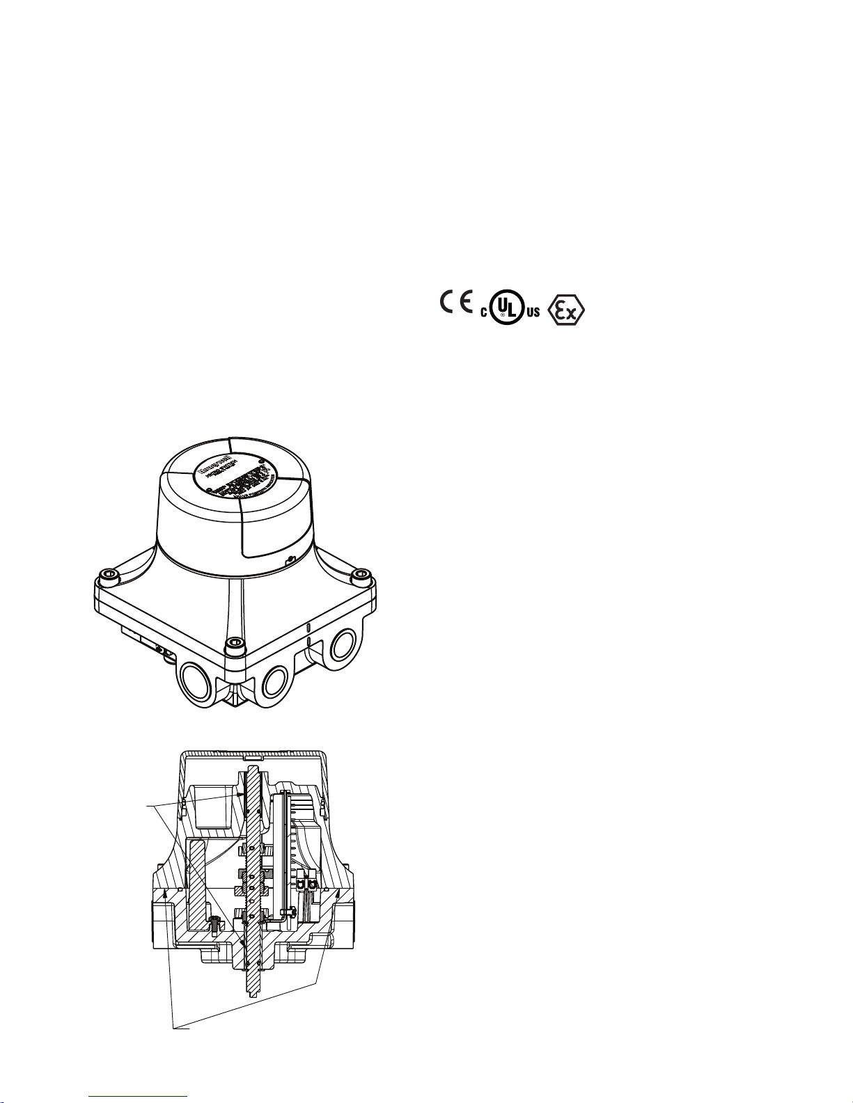
The VPX Valve Position Indicator is designed specifically for
use in potentially hazardous locations where explosive gases or
dusts may be present. To comply with explosion proof requirements the VPX has flame paths within the housing, which cool
any explosion below the ignition temperature before it reach
explosive gases or dusts in the surrounding atmosphere. Flame
paths on the VPX are 1) an extended shaft between the switch
cavity and head and 2) the cover-housing flange joint.
The equipment has a non-conducting coating and may generate an ignition-capable level of electrostatic charges under certain conditions. The user should ensure that the equipment is
not installed in a location where it may be subjected to external
conditions (such as high pressure steam) that might cause a
build up of electrostatic charges on non-conducting surfaces.
Additionally, cleaning of the equipment should be done with a
damp cloth.
Figure 1. VPX Valve Position Indicator
Figure 2. Flame Paths
2 sensing.honeywell.com
ENVIRONMENTAL PROTECTION
The VPX Valve Position Indicator is often ideal for outdoor use
or in potentially adverse environments. The enclosure is sealed
for protection against corrosion, water, dust and oil as defined
in UL 50E to enclosure types 4, 4X, 6, and 13 as well as to IP66
and IP67 as defined in IEC 60529. An ingress protection rating
of IP66 was confirmed according to IEC 600790 along with
the hazardous location approvals. A rating of IP67 was confirmed by Honeywell according to IEC 60529.
HAZARDOUS LOCATION RATINGS
IECEx UL 16.0102X
DEMKO 16 ATEX 1733X
Compliance with the Essential Health and Safety Requirements
has been assured by compliance with:
• CENELEC EN 600790 EXPLOSIVE ATMOSPHERES -
PART 0: EQUIPMENT - GENERAL REQUIREMENTS - Issue
Date 2012/08/01 - Revision Date 2013/01/01
• CENELEC EN 600791 EXPLOSIVE ATMOSPHERES -
PART 1: EQUIPMENT PROTECTION BY ENCLOSURES “d”
Issue Date 2014/10/01 Revision Date 2014/10/23
• CENELEC EN 6007911 EXPLOSIVE ATMOSPHERES
- PART 11: EQUIPMENT PROTECTION BY INTRINSIC
SAFETY “I” - Issue Date 2012/01/01
• CENELEC EN 6007931 EXPLOSIVE ATMOSPHERES -
PART 31: EQUIPMENT DUST IGNITION PROTECTION BY
ENCLOSURE “T” - Issue Date 2014/07/01 Revision Date
2014/07/22
• IEC 600790 EXPLOSIVE ATMOSPHERES. PART 0: EQUIP
MENT GENERAL REQUIREMENTS - Edition 6 - Issue Date
2011/06/01 - Revision Date 2014/10/01
• IEC 600791 EXPLOSIVE ATMOSPHERES. PART 1: EQUIP
MENT PROTECTION BY ENCLOSURES “d” - Edition 7 - Issue Date 2014/06/01 - Revision Date 2014/06/01
• IEC 6007911 EXPLOSIVE ATMOSPHERES – PART
11: EQUIPMENT PROTECTION BY INTRINSIC SAFETY
“I” - Edition 6 - Issue Date 2011/06/01 - Revision Date
2014/10/01
• IEC 6007931 EXPLOSIVE ATMOSPHERES. PART 31:
EQUIPMENT DUST IGNITION PROTECTION BY ENCLO
SURE “T” - Edition 2 - Issue Date 2013/11/01 - Revision
Date 2013/11/01
• EUROPEAN DIRECTIVE ON EQUIPMENT AND PROTEC
TIVE SYSTEMS INTENDED FOR USE IN POTENTIALLY
EXPLOSIVE ATMOSPHERES (2014/34/EU) commonly
referred to as the ATEX Directive.
• UL 1203 ExplosionProof and DustIgnitionProof Electri-
cal Equipment for Use in Hazardous (Classified) Locations,
5th Edition, Revision 20131122
• CSA C22.2 No. 30 Explosion-proof enclosures for use in
class I hazardous locations, 3rd Edition, Reaffirmed 2012
• CSA C22.2 No. 25 Enclosures for Use in Class II Groups E,
F, and G Hazardous Locations, Reaffirmed 2014
MICRO SWITCH VPX Series
ISSUE F 32312068
The explosion-proof ratings per these standards are:
II 2 G, II 2 D CL 1 DIV 1
Groups B, C, D
Ex db IIC T6 Gb
Ex tb IIIC T85°C Db
Ta 40 °C to +50 °C (Switch Code 4A or 4B)
Ta 40 °C to +60 °C (Switch Code 2A or 2B)
CL II DIV 1
Groups E, F, G
In addition, versions of the VPX with proximity switches carry an
intrinsically safe rating:
II 1 G, II 1 D
Ex ia IIC T4 Ga
Ex ia IIIC 135°C Da
Ta 40 °C to 80 °C (Switch Code 2C)
Honeywell ensures all the elements, requirements and provisions adopted comply with the product’s Ex certificate and
technical documentation. As detailed in section 5.1 of EN/IEC
600791 the requirements of the flamepath joints are met as
follows:
Table 1. Flame Path Measurements
Flame Path Comments
Shaft & bearing Cylindrical spigot joint
0,06 mm maximum gap
Cover to base Flanged joint, 9,5 mm min. surface mate
at any location within the joint, 0,038 mm
max. clearance between cover and base
North America Hazardous location ratings per UL 1203:2013
and CSA C22.2 No. 30:2003 and CSA C22.2 No. 25:1966 are:
• Division 1, Class I, Groups B, C, D
• Division 1, Class II, Groups E, F, G
NEPSI RATING
一、 防爆等级
1. 切换开关:
Ex d ⅡC T6 Gb,Ex tD A21 IP66 T85℃
Ta -40 ℃ to +50 ℃ (Switch Code 4A or 4B)
Ta -40 ℃ to +60 ℃ (Switch Code 2A or 2B)
2. NAMUR接近开关:
Ex ia ⅡC T4 Ga,Ex iaD 20 T135
Ta -40 ℃ to +80 ℃ (Switch Code 2C)
二、 产品的安全使用特殊条件
1. 产品外壳材质为铝合金,安装方式必须具有防止由于冲击或摩
擦引起点燃危险的安全措施。
2. 产品内部装配德国P+F公司生产的NCB2–V3–N0矩型接近开关已
由国家级仪器仪表防爆安全监督检验站依据GB3836.1–2010
和GB3836.4–2010防爆标准规定的要求予以认可,防爆合格证
号为GYJ16.1394X;接近开关的内部等效参数、最高使用环境温度
之间的对应关系详见GYJGYJ16.1394X防爆合格证附件。
同时,阀位回讯器的使用环境温度必须同时满足接近开关和阀
位回讯器在同一温度组别条件下对环境温度的要求。
3. 涉及到隔爆接合面尺寸的确认请参见安装说明书(文件编
号:32312068);外壳紧固件的最小屈服强度为205MPa。
三、 产品使用注意事项
1. 额定电气参数:
NAMUR开关:8.2V,接通电流<1mA,切断电流>3mA
切换开关:150VAC/15A,250VAC/10A,250VDC/0.5A
2. 本安参数:
当产品防爆标志为Ex ia ⅡC T4 Ga或Ex iaD 20 T135时,
产品的本安电气参数和内部等效参数详见GYJGYJ16.1394X
防爆合格证附件。
3. 除非防爆标志为Ex ia ⅡC T4 Ga,否则产品不得在爆炸性环
境开盖。
4. 应当保持产品外壳表面清洁,以防粉尘堆积,但严禁用压缩空
气吹扫。
5. 用户不得自行更换该产品的零部件,应会同产品制造商共同解
决运行中出现的故障,以杜绝损坏现象的发生。
6. 产品的安装、使用和维护应同时遵守产品说明书、
GB3836.13–2013“爆炸性环境第13部分:设备的修理、检修、
修复和改造”、GB3836.15–2000“爆炸性气体环境用电气设备
第15部分:危险场所电气安装(煤矿除外)”、
GB3836.16–2006“爆炸性气体环境用电气设备 第16部分:电气
装置的检查和维护(煤矿除外)”、GB15577–2007“粉尘防爆安
全规程”、GB12476.2–2010“可燃性粉尘环境用电气设备 第2
部分:选型和安装”和GB50257–2014“电气装置安装工程爆炸
和火灾危险环境 电气装置施工及验收规范”的有关规定。
SAFETY INTEGRITY LEVEL (SIL)
SIL 3 per IEC 615082 as evaluated by Sira Certification Service.
SAFETY FUNCTION
The safety function of the certified equipment is:
‘To provide indication of a monitored valve position upon rotation of the shaft via switches or proximity sensors and a visual
indicator.’
UNDETECTABLE DANGEROUS FAILURE
‘If an undetected dangerous failure of the VPX Valve Position
Indicator were to occur it would fail to respond and would give
an incorrect indication of valve position. However this would
only ever occur if both the switches or sensors and visual indicator were to have failed’.
PROOF TEST REQUIREMENTS
A maximum proof test interval of 1 year is recommended for the
VPX products. The proof test procedure must be carried out by
a competent person who is trained in safety operations and is
familiar with the VPX product. A generic proof test procedure
can be found in Table 2, however depending on application may
vary.
MATERIALS OF CONSTRUCTION
The following materials are used in the VPX Valve Position Indicator: aluminum housing, bunaN seals, polycarbonate indicator and indicator cover and stainless steel shaft and fasteners.
The suitability of these materials for the application environment is solely up to the customer.
ELECTROMECHANICAL SNAP ACTION
SWITCHES
The electrical ratings of the VPX with snap-action switches are
• 15 A @ 150 Vac, 10 A @ 250 Vac, 0.5 A @ 250 Vdc
Sensing and Internet of Things 3
MICRO SWITCH VPX Series
A certied associated apparatus with
VPX VALVE POSITION INDICATOR
SWITCHING AMPLIFIER
Table 2. Proof Test Procedure
Step Action
1
Bypass safety PLC and/or take alternative actions to avoid false trip.
2
Visually inspect the VPX Valve Position Indicator for signs of wear or damage.
3
Perform the proof test by manually operating the valve being monitored and perform a full stroke.
4
Monitor the visual indication and switch outputs and record test results as per local procedure.
5
Remove the safety PLC bypass and restore the safety system for normal operation.
MCTF Mechanical Life(Cycles) MCTF Electrical Life(Cycles) Highest SIL
S.NO Catalog Value Reference Value Reference SIL Level HF T1SC2PTI
VPX Series - Electro-
mechanical snap-
1
action switches loaded
at 16 A, 250 Vac
VPX Series - Electro-
mechanical snap-
2
action switches loaded
at 0.5 A, 250 Vdc
VPX Series - Intrensi-
3
cally safe proximity
switches
Notes: 1 HFT: Hardware Fault Tolerance; 2 SC: Systematic Capability; 3 PTI: Proof Test Interval; 4 PT: Product Type
> 500,000 with
Single Sided
Confidence Limit
of 100%.
> 500,000 with
Single Sided
Confidence Limit
of 100%.
> 500,000 with
Single Sided
Confidence Limit
of 100%.
SIRA TA
16002/01
SIRA TA
16002/01
SIRA TA
16004/01
> 25,000 with
Single Sided
Confidence
Limit of 50%
> 10,000 with
Single Sided
Confidence
Limit of 100%.
> 50,000 with
Single Sided
Confidence
Limit of 100%.
SIRA TA
16001/01
SIRA TA
16001/01
SIRA TA
16003/01
SIL 3 0 SC 3 1 year Type A
SIL 3 0 SC 3 1 year Type A
SIL 3
SC 3
0
ISSUE F 32312068
3
1 year Type A
PT
4
Staandard Reference
IEC
615082:
2010
IEC
615082:
2010
IEC
615082:
2010
SIRA FSP
16005/00
SIRA FSP
16005/00
SIRA FSP
16005/00
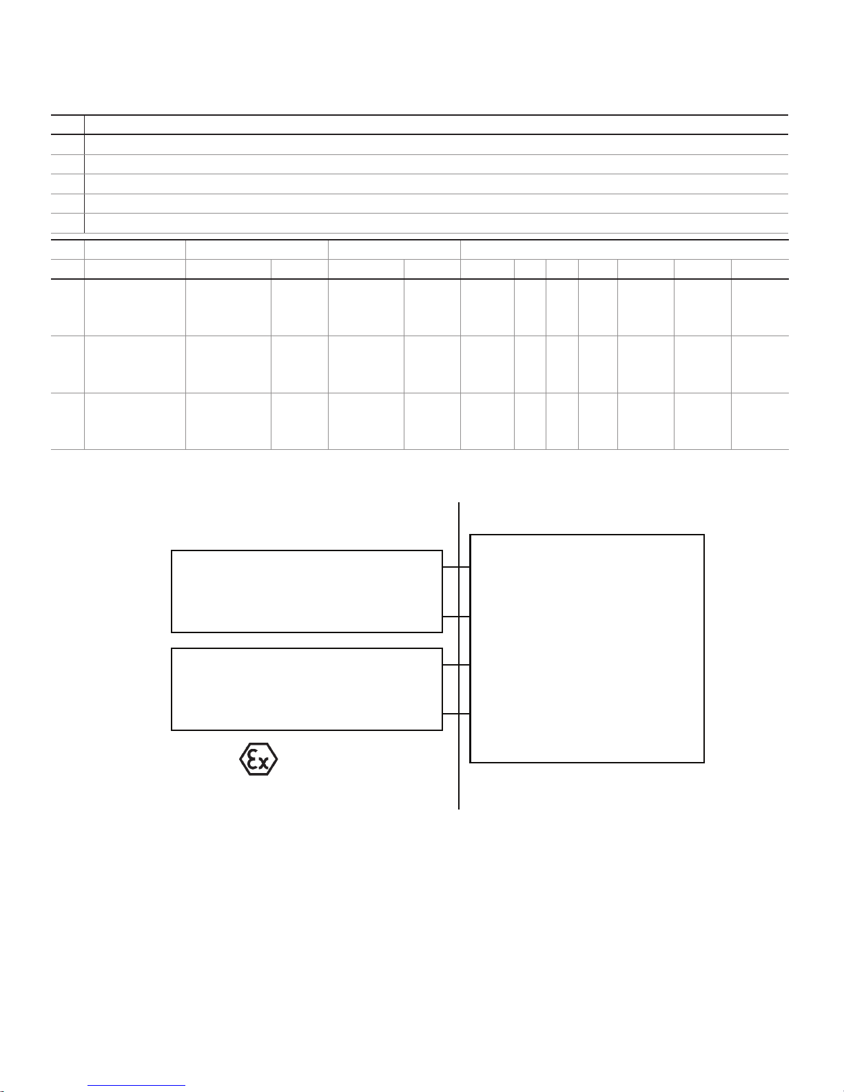
Figure 3. Intrinsically Safe Zone Diagram
Ui = 16V
Proximity
Switch #1
Proximity
Switch #2
Ii = 25 mA
Pi = 34 mW
Ci = 100 nF
Li = 100 µH
Ui = 16V Io ≤ Ii
Ii = 25 mA
Pi = 34 mW
Ci = 100 nF Lo ≥ Li + Lcable
Li = 100 µH
Zone 0, 1, 2
HAZARDOUS (CLASSIFIED) LOCATION NON-HAZARDOUS LOCATION
INTRINSICALLY SAFE PROXIMITY SWITCHES
A VPX equipped with proximity switches is considered intrinsically safe when used with an appropriate switching amplifier,
also referred to as an associated apparatus, which complies
with EN 6094756:2000 or IEC 6094756:1999. The amplifier contains a dc source to supply the control circuit and is
controlled by the variable internal resistance of the proximity
switch. This amplifier is placed outside of the hazardous area. A
diagram of the typical installation is shown in Figure 3.
Cable capacitance, Ccable, plus intrinsically safe equipment
capacitance, Ci, must be less than the marked capacitance, CO,
shown on any associated apparatus used. The same applies for
4 sensing.honeywell.com
Switch 1 L+
Switch 1 L-
Switch 2 L+
Switch 2 L-
zone and group approval and
with entity pa rameters:
Uo ≤ Ui
Po ≤ Pi
Co ≥ Ci + Ccable
inductance (Lcable, Li and Lo, respectively). Where the cable
capacitance and inductance per foot are not known, the following values shall be used: Ccable = 200 pF/m., Lcable = 1 μH/m.
The associated apparatus output current must be limited by a
resistor such that the output voltage-current plot is a straight
line drawn between open-circuit voltage and short-circuit current. The associated apparatus must be installed in accordance
with its manufacturer’s control drawing. When required by the
manufacturer’s control drawing, the associated apparatus must
be connected to a suitable ground electrode per local installation codes, as applicable. The resistance of the ground path
must be less than 1 Ohm. Associated apparatus must not be
 Loading...