

Page 1
BEFORE INSTALLATION
VP527A Pneumatic
Water Valve
INSTALLATION INSTRUCTIONS
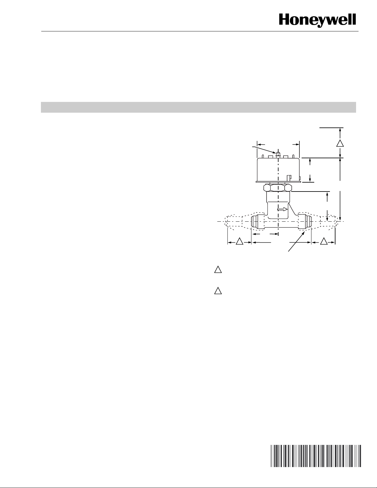
Allow sufficient room for servicing or removing the valve. See
Fig. 1 for space requirements. This valve can be installed in
any position. The direction of the flow should be in the same
direction as the arrow cast on the valve body.
INSTALLATION
1. Mount the valve. See Fig. 1 and 2.
2. Connect the control air tubing.
NOTE: No calibration or adjustments are necessary.
AIR CONNECTION
FOR 1/4 IN. (6 MM)
O.D. PLASTIC TUBING
1 2 ALLOW 1-1/2 IN. (38 MM) MINIMUM CLEARANCE TO SERVICE VALVE,
2-1/2 IN. (63 MM) CLEARANCE TO CONNECT TUBING STRAIGHT TO
CONNECTOR. IF CLEARANCE IS LESS THAN 2-1/2 IN. (63 MM),
USE AN ELBOW CONNECTOR.
ALLOW 1-3/8 IN. (35 MM) MINIMUM CLEARANCE TO REMOVE VALVE.
2-1/4 (57) DIA.
1-1/2
(38)
1-3/8
(35)
3-1/8 (79)
1/2 IN. (12MM) X 45° SAE FLARED TUBE
CONNECTION - 2 (NOT FURNISHED)
1-5/8
(41)
22
3-13/16
M18348
Fig. 1. VP527A dimensions in in. (mm).
1
(97)
® U.S. Registered Trademark
Copyright © 2002 Honeywell • All Rights Reserved
95-5555EF
Page 2

VP527A PNEUMATIC WATER VALVE
Printed in U.S.A. on recycled
paper containing at least 10%
post-consumer paper fibers.
USE 1/2 IN. (6 MM) O.D.
COPPER TUBING
IN
Fig. 2. VP527A connectors and copper tubing dimensions in. (mm).
TYPICAL OPERATION
An increase in control air pressure moves the valve stem
toward the closed position, modulating flow through the valve.
CONTROL AIR
VP527A
SYSTEM
SUPPLY
N.O.
1/2 IN. O.D. X 45° SAE
FLARED TUBE
CONNECTORS (2)
(NOT FURNISHED)
M18349
OUT
Fig. 3. VP527A typical operation.
Automation and Control Solutions
Honeywell Honeywell Limited-Honeywell Limitée
1985 Douglas Drive North 35 Dynamic Drive
Golden Valley, MN 55422 Scarborough, Ontario
95-5555EF J.H. Rev. 1-02
M1V 4Z9
M18350
customer.honeywell.com
Page 3

AVANT D’INSTALLER CE PRODUIT…
Vanne pneumatique
à eau VP527A
NOTICE D’INSTALLATION
Il faut s'assurer qu«il y a suffisamment d'espace pour
l'entretien et le démontage de la vanne. Voir la Fig. 1. Cette
vanne peut être installée dans n'importe quelle position.
L'eau doit s'écouler dans le sens indiqué par la flèche sur le
corps de la vanne.
INSTALLATION
1. Monter la vanne. Voir les Fig. 1 et 2.
2. Raccorder la canalisation d'air de commande.
REMARQUE : Il n'y a ni étalonnage ni réglage à effectuer.
RACCORD D'AIR POUR
UNE CANALISATION
EN PLASTIQUE DE
6 MM (1/4 PO)
DIAM. EXT.
LAISSER UN DÉGAGEMENT MINIMAL DE 38 MM (1-1/2 PO) POUR
1
L'ENTRETIEN DE LA VANNE ET DE 63 MM
(2-1/2 PO) POUR LE RACCORDEMENT DIRECT DE LA
CANALISATION AU RACCORD D'AIR. SI LE DÉGAGEMENT EST
INFÉRIEUR À 63 MM (2 1/2 PO), UTILISER UN COUDE.
2
LAISSER UN DÉGAGEMENT MINIMAL DE 35 MM (1-3/8 PO) POUR
RETIRER LA VANNE.
57 (2-1/4) DIAM.
38
(1-1/2)
35
(1-3/8)
79 (3-1/8)
RACCORD DE 12 MM (1/2 PO)
ÉVASÉ À 45° SAE (2 - NON FOURNIS)
Fig. 1. Encombrement de la vanne
VP527A en mm (po).
41
(1-5/8)
22
1
97
(3-13/16)
MF18348
® Marque de commerce déposée aux É.-U.
Copyright © 2002 Honeywell Tous droits réservés
95-5555EF
Page 4

VANNE PNEUMATIQUE Ω EAU VP527A
UTILISER UNE CANALISATION EN
CUIVRE DE 6 MM (1/2 PO) DIAM. EXT.
ENTRÉE
Fig. 2. Encombrement de la canalisation en cuivre et des raccords de la VP527A en mm (po).
FONCTIONNEMENT TYPE
Une augmentation de la pression d'air de commande fait
déplacer la tige de la vanne vers la position de fermeture,
modulant ainsi l«écoulement dans la vanne.
AIR DE
COMMANDE
VP527A
SYSTÈME
D'ALIMENTATION
N.O.
2 RACCORDS ÉVASÉS À 45° SAE
DE 6 MM (1/2 PO) DIAM.
EXT. (NON FOURNIS)
SORTIE
MF18349
MF18350
Fig. 3. Fonctionnement type de la VP527A.
By using this Honeywell literature, you agree that Honeywell will have no liability for any damages arising out of your use
or modification to, the literature. You will defend and indemnify Honeywell, its affiliates and subsidiaries, from and against
any liability, cost, or damages, including attorneys’ fees, arising out of, or resulting from, any modification to the literature
by you.
Solutions de régulation et d’automatisation
Honeywell Honeywell Limited-Honeywell Limitée
1985 Douglas Drive North 35, Dynamic Drive
Golden Valley, MN 55422 Scarborough (Ontario)
95-5555EF J.H. Rév. 1-02 customer.honeywell.com
M1V 4Z9
Imprimé aux États-Unis sur du papier
recyclé contenant au moins 10 %
de fibres post-consommation.
 Loading...