

Page 1
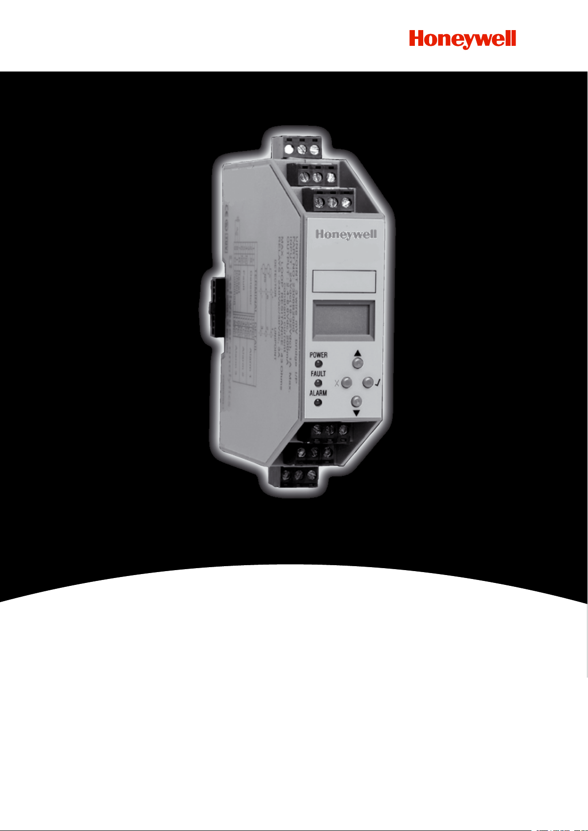
Operating Instructions
Unipoint Flammable and Toxic
Gas Detection Controller
Page 2

UNIPOINT OPERATING MANUAL 2306M5001 MAN0638 ISSUE 7 01/2011
1 Safety
Ensure that this manual is read and understood BEFORE installing / operating / maintaining the
equipment.
WARNINGS
Unipoint is designed for installation and use in indoor safe area
non-explosive atmospheres. Installation must be in accordance
with the recognized standards of the appropriate authority in the
country concerned.
Unipoint should be installed inside a lockable enclosure or in a
secure location to prevent unauthorized access.
Before carrying out any work ensure local regulations and site
procedures are followed. Work must only be conducted by trained
personnel. Take any necessary precautions to prevent false alarms.
The detectors/sensors that the controller connects to may be used
for gas detection in hazardous atmospheres. Refer to the individual
detector/sensor instructions for their details.
The fault and alarm relay outputs may be used to switch voltages
in excess of 50Vac. Ensure circuits have DOUBLE or REINFORCED
insulation and are segregated in accordance with the voltage being
switched and access is restricted to authorized personnel only.
Unipoint must be zero and span calibrated with the
detector before operation.
Disposal should be according to local waste management
requirements and environmental legislation. Alternatively contact
your local Honeywell Analytics representative.
Honeywell Analytics can take no responsibility for installation and/or use of its equipment if
this is not done in accordance with the appropriate issue and/or amendment of the manual.
The reader of this manual should ensure that it is appropriate in all details for the exact
equipment to be installed and/or operated. If in doubt, contact Honeywell Analytics for advice.
Every effort has been made to ensure the accuracy of our documents; however,
Honeywell Analytics can assume no responsibility for any errors or omissions in our documents
or their consequences.
Honeywell Analytics greatly appreciates being informed of any errors or omissions that
may be found in the contents of any of our documents. For information not covered in this
document, or if there is a requirement to send comments/ corrections about this document,
please contact Honeywell Analytics.
Honeywell Analytics reserve the right to change or revise the information supplied in this
document without notice and without obligation to notify any person or organization of such
revision or change. If information is required that does not appear in this document, contact
the local distributor/agent or Honeywell Analytics.
2
Page 3

UNIPOINT OPERATING MANUAL 2306M5001 MAN0638 ISSUE 7 01/2011
2 Table of Contents
1 Safety...................................................................................................................................... 2
2 Table of Contents.................................................................................................................... 3
3 Introduction............................................................................................................................. 4
4 Installation............................................................................................................................... 4
4.1 Mechanical Installation......................................................................................................... 4
4.2 Electrical Installation............................................................................................................ 6
4.2.1 Unipoint Controller Selection............................................................................................ 6
4.2.2 Power Connection............................................................................................................ 6
4.2.3 Terminal Detail................................................................................................................... 7
4.2.4 Detector Types.................................................................................................................. 7
4.2.5 Generic Detector Wiring Schematics................................................................................ 8
4.3 Maximum Cable Lengths..................................................................................................... 9
4.3.1 mA Detectors.................................................................................................................... 9
4.3.2 mV Detectors.................................................................................................................... 9
5 Default Conguration.............................................................................................................. 10
5.1 Unipoint mV Input Version................................................................................................... 10
5.2 Unipoint 4-20mA Input Version............................................................................................ 10
6 Switch On................................................................................................................................ 11
7 Initial Conguration................................................................................................................. 11
7.1 Setting Detector type (mA version only)............................................................................... 12
8 Normal Operation.................................................................................................................... 13
8.1 Display and Pushbutton Layout........................................................................................... 13
8.2 Normal Operation LCD Event Codes.................................................................................... 14
8.3 Display, Sounder and Relay Operation................................................................................. 14
8.4 Accept/Resetting Alarms...................................................................................................... 14
8.5 Fault Codes........................................................................................................................... 15
8.6 Inhibit.................................................................................................................................... 15
8.7 Overrange............................................................................................................................. 15
8.8 Self Test................................................................................................................................ 15
9 Conguration........................................................................................................................... 16
10 Ranges and Units.................................................................................................................. 17
11 Alarm Relay On/Off Delay...................................................................................................... 17
11.1 Alarm Relay On Delay......................................................................................................... 17
11.2 Alarm Relay Off Delay......................................................................................................... 18
12 Maintenance.......................................................................................................................... 18
13 Ordering Information.............................................................................................................. 19
14 Warranty Statement............................................................................................................... 19
15 Appendix A- Specication..................................................................................................... 20
16 Approvals............................................................................................................................... 21
17 EC Declaration of Conformity................................................................................................ 22
18 Notes...................................................................................................................................... 23
3
Page 4
UNIPOINT OPERATING MANUAL 2306M5001 MAN0638 ISSUE 7 01/2011
3 Introduction
Unipoint is a self-contained single channel gas detection controller for use in indoor safe areas.
It is designed for use with any mV ammable gas detector as well as any 2 wire or 3 wire
4-20mA source gas detector*. Unipoint is DIN rail mounted and displays gas concentration,
alarm, fault and status information via its backlit LCD and LEDs, as well as providing a built
in audible alarm. A keypad located below the display provides the facility to make changes
to the system conguration. Unipoint is powered from 24VDC via the DIN rail. The detectors
are connected to the controller via terminals on the side of the controller where terminals for
remote inhibit/reset and output relays are also located.
There are two versions of Unipoint controller available. The mV version is for use with 3 wire
mV ammable gas detectors such as the Signalpoint or Sensepoint range of ammable
detectors. The 4-20mA version is for use with 2 wire and 3 wire 4-20mA source detectors such
as the Signalpoint or Sensepoint range of toxic and oxygen detectors. It has 4 buttons: ‘s’
up, ‘t’ down, ‘x’ reset and ‘3’ OK, that are used navigate through the menus and change the
conguration settings.
*All Honeywell Analytics gas detectors and third party detectors subject to overall power
requirements.
4 Installation
WARNING
Unipoint is designed for installation and use in indoor safe area
non-explosive atmospheres. Installation must be in accordance
with the recognised standards of the appropriate authority in the
country concerned. Prior to carrying out any installation ensure local
regulations and site procedures are followed. The detectors used with
Unipoint are often designed for use in hazardous atmospheres. Refer
to the individual detector instructions for details of their installation.
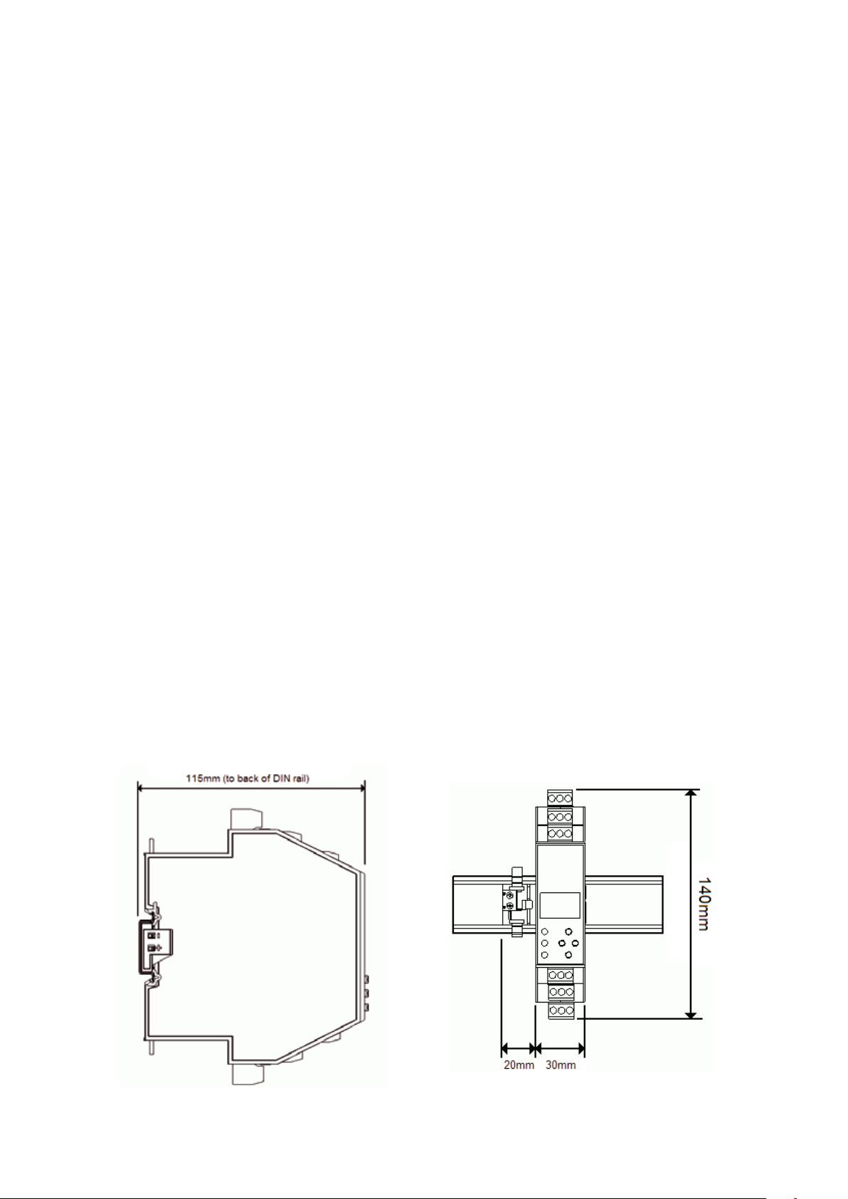
4.1 Mechanical Installation
Outline Dimensional Drawing
4
Page 5
UNIPOINT OPERATING MANUAL 2306M5001 MAN0638 ISSUE 7 01/2011
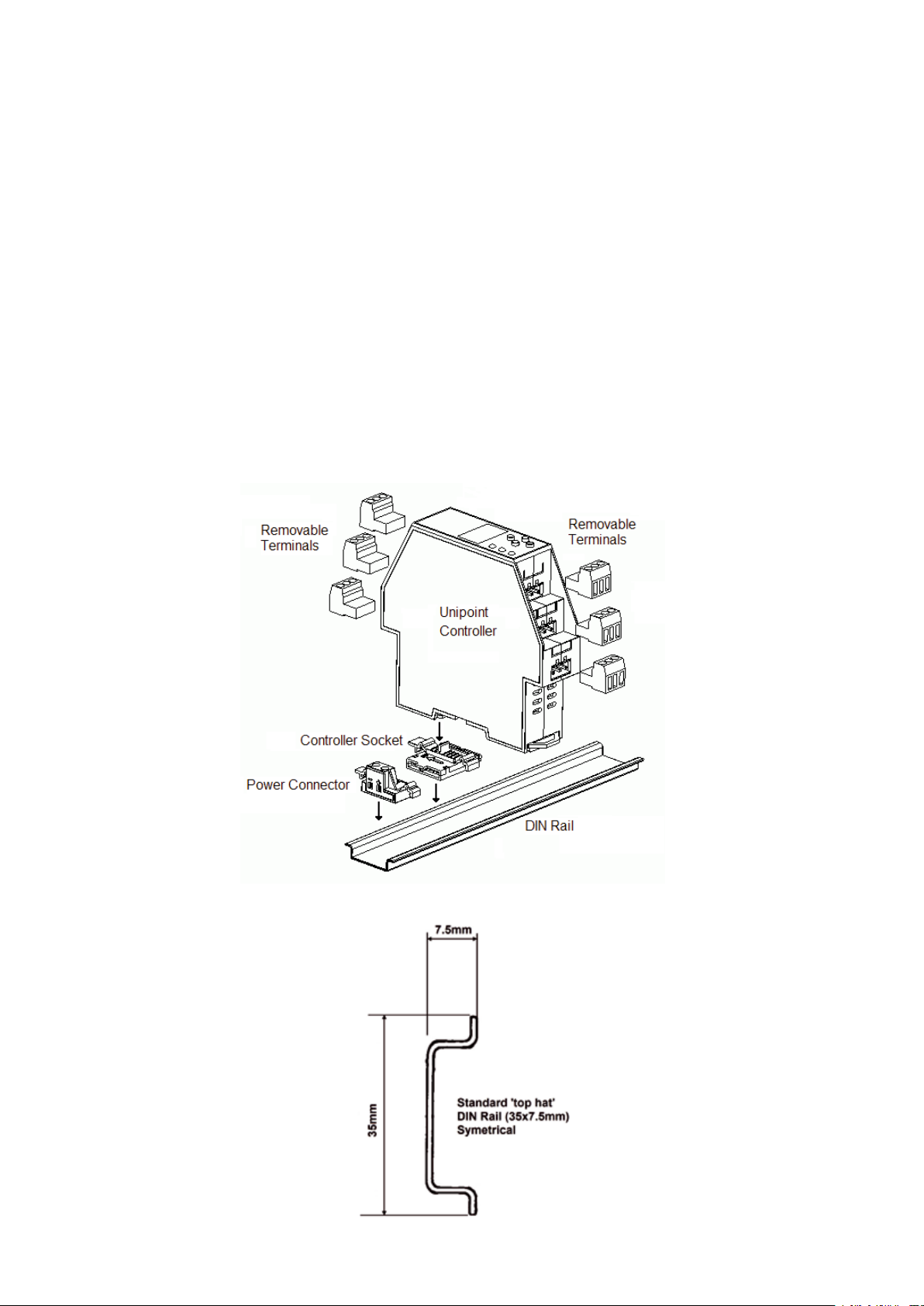
The Unipoint controller is mounted on standard symmetrical ‘top hat’ DIN Rail (35 x 7.5mm).
To attach the Unipoint controller to the DIN rail follow the procedure below use the Installation
Diagram as reference.
1. Clip the Unipoint controller socket on to the DIN rail (note the correct orientation from the
diagram below).
2. Clip the power connector on to the DIN rail beside the controller socket.
3. Slide the connector and socket together until clip engages.
4. Attach the Unipoint Controller on to the socket by gently but rmly pushing it down onto the
socket until it clips in place.
5. Additional Unipoint Controllers can be added to the DIN rail on the right hand side of the rst
unit. Clip additional controller sockets to rail and slide together until clips engage. Then attach
the additional Unipoint Controllers.
Note: If mounting the Unipoint controller(s) inside an enclosure, ensure that the temperature inside
the enclosure does not exceed the specified operating temperature.
Installation Drawing
DIN Rail Drawing
5
Page 6

UNIPOINT OPERATING MANUAL 2306M5001 MAN0638 ISSUE 7 01/2011
4.2 Electrical Installation
4.2.1 Unipoint Controller Selection
Detector Gas Type Nº Wires Unipoint Controller
Required
Signalpoint Flamable
Toxic
Sensepoint Flamable
Toxic
Sensepoint Plus Flamable
Toxic
4.2.2 Power Connection
Max number of Unipoint controllers on one DIN Bus
Detector Type Max number of
3 wire mV 8
2 wire mA 8
3 wire mA 4
Unipoint Controller Maximum Power Consumption
3
2
3
2
3
3
controllers
mV
mA
mV
mA
mA
mA
Unipoint
Controller status Relays Power
version
mV Normal operation, no faults, no alarms.
Zero cable resistance.
mV Normal operation, no faults, no alarms.
Max loop cable resistance (28 ohms)
mV All alarms, no faults. Max cable
resistance (28 ohms)
mA Normal operation, no faults, no alarms.
Inclusive of 2 wire signal loop current.
mA All alarms, no faults. Inclusive of 2 wire
signal loop current.
1 includes power to detector
2 excludes power to 3 wire mA detector.
All controllers with default conguration.
Fault Alarm
Energised De energised 2.4W
Energised De energised 3.6W
Energised Energised 4.8W
Energised De energised 1.8W
Energised Energised 3.0W
1
1
1
2
2
6
Page 7
UNIPOINT OPERATING MANUAL 2306M5001 MAN0638 ISSUE 7 01/2011
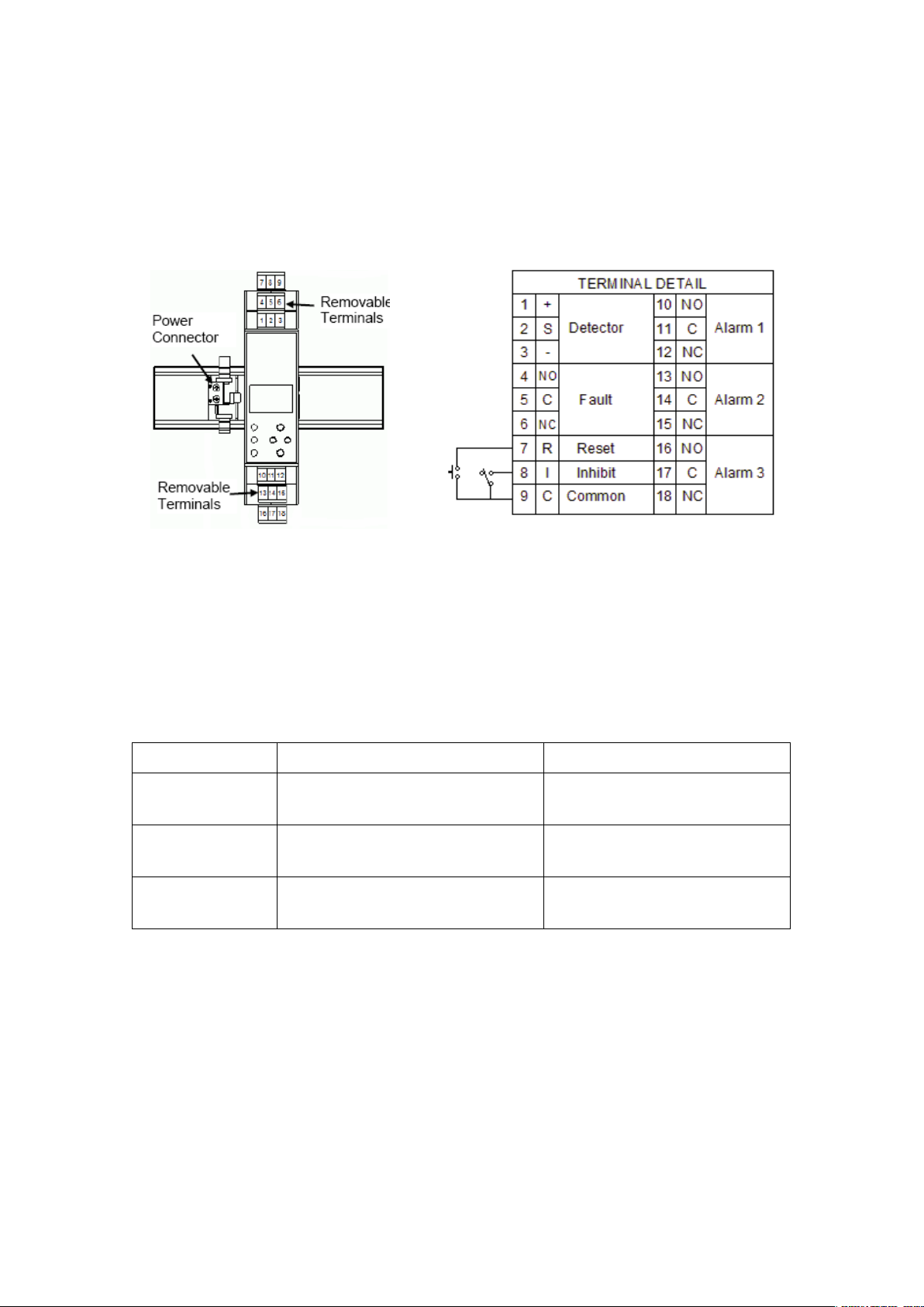
4.2.3 Terminal Detail
All electrical connections except power are made via removable terminals located on the top
and bottom of the controller. The power connection is made via the power connector attached
to the DIN rail.
For security we recommend the use of Key Switches for the remote reset and inhibit inputs
mounted on the front of the enclosure in which the Unipoint is mounted.
4.2.4 Detector Types
Unipoint can accept signals from three types of detector. The table below summarizes the
types of detector compatible with Unipoint.
Type of detector Output to detector Recommended detector
2 wire 4-20mA Controller Input (18-32Vdc)-1.5*Vdc,
30mA (max). Sense resistor 33 Ohms.
3 wire 4-20mA
source
Controller Input (18-32Vdc)-1.5*Vdc,
0.5A (max). Sense resistor 33 Ohms.
3 wire mV bridge 2.4-8.6V, 200mA constant current.
Max cable loop resistance 28 Ohms.
* Voltage drop in Unipoint Controller
Signalpoint or Sensepoint Toxic
and Oxygen
Sensepoint Plus
Signalpoint or Sensepoint
Flammable
7
Page 8
UNIPOINT OPERATING MANUAL 2306M5001 MAN0638 ISSUE 7 01/2011
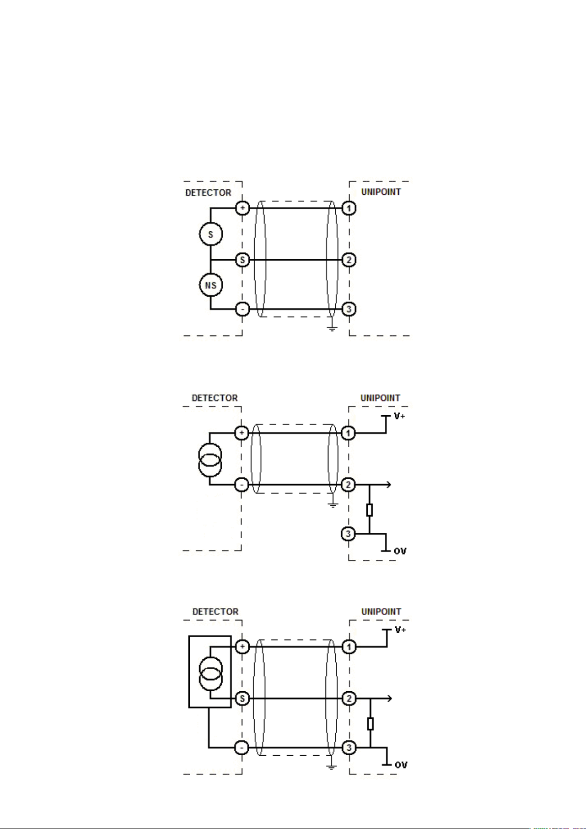
4.2.5 Generic Detector Wiring Schematics
To connect the detector to the Unipoint use a 2 or 3 wire cable (as appropriate) that is suitably
armoured (e.g. Steel Wire Armour) or conduit according to local requirements. Acceptable wire
cross sectional area is from 0.5 to 1.5mm2 with overall screen. Connect the screen to ground at
the enclosure that the Unipoint is mounted in.
3 Wire mV Bridge
2 Wire 4-20mA
3 Wire 4-20mA Source
8
Page 9

UNIPOINT OPERATING MANUAL 2306M5001 MAN0638 ISSUE 7 01/2011
4.3 Maximum Cable Lengths
4.3.1 mA Detectors
To calculate the maximum cable run length from power source to the detector refer to the
following example diagram and formula.
Rloop = (Vcontroller - 1.5V - Vdetector min) / Idetector
Maximum cable run length = Rloop / cable per metre resistance where:
Rloop = maximum working cable loop resistance
Vcontroller = maximum available supply voltage at controller
Vdetector min = minimum voltage at which the connected sensor can operate
(sensor dependent, see individual sensor technical manual/
data sheets)
Idetector = sensor maximum drawn current. 30mA for 2 wire mA detectors.
See individual detector technical manual/data sheets for max power
consumption of 3 wire detectors.
4.3.2 mV Detectors
To calculate the maximum cable run length to the detector refer to the following typical
example cable resistances. Max cable loop resistance = 28 ohms.
Solid Copper Conductor
Cross Sectional Area Maximum resistance at 20ºC
(mm2) AWG (ohm/bucle/km)
0.50 21 72
0.75 19 50
1.00 18 36
1.50 16 24
Stranded Copper Conductor
Cross Sectional Area Maximum resistance at 20ºC
(mm2)
0.50 21 73.6
0.75 19 49
AWG
(ohm/bucle/km)
1.00 18 35.2
1.50 16 23.4
9
Page 10

UNIPOINT OPERATING MANUAL 2306M5001 MAN0638 ISSUE 7 01/2011
5 Default Conguration
Unipoint has user congurable settings that allow the set up of the system to individual
application requirements. Unipoint is supplied from the factory with a default conguration.
These congurations are based on settings typically used in gas detection systems.
Details of how to recongure Unipoint are given in section 7.
5.1 Unipoint mV Input Version
Function Default conguration
Password 000 (Disabled)
Display range and units 0-100%LEL
Alarm Relay 1 Alarm level 1 10%LEL (Rising)
Alarm Relay 2 Alarm level 2 25%LEL (Rising)
Alarm Relay 3 Alarm level 3 50%LEL (Rising)
Fault Relay Non-latching, normally energized, de-energizes on fault.
Inhibit Controller inhibit activates fault relay.
Non-latching, normally de energized, energizes on alarm.
Relay activation delay=0 seconds
Relay de-activation hold=0 seconds
(Single Pole change over, 240Vac/30Vdc, 3A max)
Non-latching, normally de energized, energizes on alarm.
Relay activation delay=0 seconds
Relay de-activation hold=0 seconds
(Single Pole change over, 240Vac/30Vdc, 3A max)
Latching, normally de energized, energizes on alarm.
Relay activation delay=0 seconds
Relay de-activation hold=0 seconds
(Single Pole change over, 240Vac/30Vdc, 3A max)
(Single Pole change over, 240Vac/30Vdc, 3A max)
5.2 Unipoint 4-20mA Input Version
Function Default conguration
Password 000 (Disabled)
Display range and units 0-100ppm
Current input 0 mA Fault (open circuit)
Alarm Relay 1 Alarm level 1 10% of full scale (Rising)
Alarm Relay 2 Alarm level 2 25% of full scale (Rising)
Alarm Relay 3 Alarm level 3 50%LEL (Rising)
Fault Relay Non-latching, normally energized, de-energizes on fault.
Inhibit Controller inhibit activates fault relay and de-activates alarm relays.
Detector Type 2 Wire 4-20mA
4.0 to 20.0mA Gas reading (normal operation)
1.5 to 2.5mA Inhibit from sensor (configuration mode)
>20.0mA Overrange
Non-latching, normally de energized, energizes on alarm.
Relay activation delay=0 seconds
Relay de-activation hold=0 seconds
(Single Pole change over, 240Vac/30Vdc, 3A max)
Non-latching, normally de energized, energizes on alarm.
Relay activation delay=0 seconds
Relay de-activation hold=0 seconds
(Single Pole change over, 240Vac/30Vdc, 3A max)
Latching, normally de energized, energizes on alarm.
Relay activation delay=0 seconds
Relay de-activation hold=0 seconds
(Single Pole change over, 240Vac/30Vdc, 3A max)
(Single Pole change over, 240Vac/30Vdc, 3A max)
Field inhibit active (1.5 to 2.5mA on detector input).
10
Page 11

UNIPOINT OPERATING MANUAL 2306M5001 MAN0638 ISSUE 7 01/2011
6 Switch On
After connecting power, the controller enters a self test routine: All LCD segments ash, the
fault and alarm LED ash, the sounder operates three times, the RAM, ROM and EEPROM are
checked and the software version is displayed. If no faults are found (see section 7.5 for fault
codes) the unit enters a detector warm up period indicted by a count down from 60 to 0 on the
display. During this time the controller is inhibited (‘Inh’) so all alarms and faults are inactive.
At the end of the warm-up period the controller checks for detector and eld wiring faults. If a
fault is found, the fault code is displayed (see section 7.5 for fault codes). If no fault is found
the controller enters normal operation and will display current gas reading and alarm(s) if
appropriate.
7 Initial Conguration
WARNING
Unipoint must be zero and span calibrated with the detector
before operation.
If the default conguration shown in section 5.1 (mV type controller) or 5.2 (mA type controller)
does not match the application requirements, follow the procedures below to recongure the
controller.
Notes: If using a mA version controller with a 3 wire mA type detector, carry out the
procedure in section 7.1 rst to set the correct detector type.
If conguring the controller for use with an Oxygen detector, skip the ‘Set zero’ instructions
(steps 7-14) and use 20.9% (background air oxygen level) as the span calibration point.
After completing all the steps in a menu, the 3 button must be pressed to save the changes.
Press x at any time to ignore the changes made in the current menu.
1. Press the st buttons together to enter the conguration mode.
2. Press 3 to enter the ‘Set Range and Units (FS)’ menu.
3. The default range ashes. Press the st buttons to select the required range.
4. Press 3 to set the new range.
5. The default units start ashing. Press the st buttons to select the required units.
6. Press 3 to set the new units. (See section 9 for available ranges and units).
7. Press the t button to select the ‘Set Zero (0)’ menu.
8. Press 3 to enter the ‘Set Zero (0)’ menu.
9. The current zero gas reading is displayed.
10. Apply zero gas to the detector.
11. Press 3 when the reading is stable.
12. The display will show ‘---’ while calculating the zero point and then ‘0’ when complete. If
the zero fails ‘FFF’ is displayed.
13. Remove the zero gas from the detector.
14. Press 3 to complete the zero calibration.
15. Press the t button to select the ‘Set Span (S)’ menu.
16. Press 3 to enter the ‘Set Span (S)’ menu.
17. 50% of the set range ashes.
18. Press st buttons to set the concentration of the span calibration gas concentration
being used.
19. Press 3 to set the span calibration concentration.
20. Apply the span calibration gas to the detector.
21. The ‘live’ gas reading is displayed.
22. If the reading is too low ‘S-L’ is displayed, if too high ‘S-H’ is displayed.
11
Page 12

UNIPOINT OPERATING MANUAL 2306M5001 MAN0638 ISSUE 7 01/2011
23. When the reading is stable press 3.
24. ‘---’ is displayed while calculating the new span.
25. The display then shows the new span value. If span fails ‘FFF’ is displayed.
26. Remove the span gas from the detector and allow the display to return to zero.
Note: Allowing the reading to return to zero before exiting ensures no accidental alarms are
triggered.
27. Press 3 to return to the menu.
28. Press the 3 button to select the ‘Set Alarms (A1)’ menu.
29. Press 3 to enter the ‘Set Alarms (A1)’ menu.
30. The current alarm 1 set point ashes.
31. Press st buttons to change the A1 set point.
32. Press 3 to conrm.
33. The display shows the current alarm relay on delay in seconds.
34. Press st buttons to change the alarm relay on delay.
35. Press 3 to conrm.
36. The display shows the current alarm relay off (hold) delay in seconds.
37. Press st buttons to change the alarm relay off delay.
38. Press 3 to conrm.
39. The display shows the current alarm 1 relay conguration.
40. Press st buttons to select either ‘F’ for falling or ‘r’ for rising alarm point.
41. Press 3 to conrm.
42. Press st buttons to select either ‘E’ for normally energized or ‘d’ for normally de-energized relay.
43. Press 3 to conrm.
44. Press st buttons to select either ‘L’ for latching or ‘n’ for non-latching relay.
45. Press 3 to conrm.
46. The display now shows the current alarm 2 level.
47. Repeat steps 31 to 46 for alarm 2 and then alarm 3.
48. Press ‘x’ to return to normal operation.
Note: For details of other settings in the configuration menu refer to section 9.
7.1 Setting Detector type (mA version only)
The default detector type setting for a mA version controller is 2 wire. If using a 3 wire mA type
detector carry out the procedure below:
1. Press the st buttons together to enter the conguration mode.
2. Press s or t buttons to select the ‘Detector Type (IP)’ menu.
3. The current detector input type ashes (2L=2 wire mA).
4. Press the st buttons to select 3L=3 wire mA).
5. Press 3 to conrm.
6. Press x to return to normal operation.
7. Follow the procedures in section 7 to complete the initial conguration.
12
Page 13

UNIPOINT OPERATING MANUAL 2306M5001 MAN0638 ISSUE 7 01/2011
8 Normal Operation
In normal operation the green Power LED is illuminated and the 1st line of the LCD shows the
current gas reading. The 2nd line is used to display text codes that provide additional information about the type of event that has occurred. An alarm, fault/inhibit LED and built in sounder
are also used when signaling events.
8.1 Display and Pushbutton Layout
Gas Label Area*
Gas Reading
Measurement Units
Event Code
s Pushbutton
Power LED
Fault/Inhibit LED
3 Pushbutton
Alarm LED
t Pushbutton
X Pushbutton
*A packet of stick on gas labels are supplied with each Unipoint Controller
13
Page 14

UNIPOINT OPERATING MANUAL 2306M5001 MAN0638 ISSUE 7 01/2011
8.2 Normal Operation LCD Event Codes
The display event codes are shown below:
NORMAL OPERATION DISPLAY TEXT CODES
CODE EVENT TYPE
A - 1 Alarm point 1 exceeded
A - 2 Alarm point 2 exceeded
A - 3 Alarm point 3 exceeded
O F F All outputs disabled
F X X Fault. XX=Fault code
I n h Remote or eld* inhibit
8.3 Display, Sounder and Relay Operation
The table below shows the default operation of the display, sounder and relays for given
events.
EVENT LCD LEDS* SOUNDER RELAY
ALARM FAULT/INH A1 A2 A3 F
Alarm 1 threshold exceeded A-1 ashing off on X
Alarm 2 threshold exceeded A-2 ashing off on X X
Alarm 3 threshold exceeded A-3 ashing off on X X X
Fault FXX off ashing on X
Inhibit Inh off ashing off X
Overange Or/A3 ashing off on X X X
*LED ash frequency: Alarm = 2Hz, Fault = 1Hz and Inhibit = 0.5Hz
8.4 Accept/Resetting Alarms
In normal operation, the X button on the controller front panel or a switch connected to the
remote reset terminal is used to reset/accept alarm events. The effect of reset/accept
dependent on gas reading and alarm latching setting is described below:
Gas reading still exceeds alarm threshold Gas reading below alarm threshold
Latched alarm Sounder stops. Flashing alarm LED changes
to steady. Gas reading and alarm code
displayed on LCD. Alarm relay remains in
alarm state.
Unlatched alarm Sounder stops. Flashing alarm LED changes
to steady. Gas reading and alarm code
displayed on LCD. Alarm relay remains in
alarm state.
Sounder stops. Alarm LED is turned off. The
LCD alarm code clears. Alarm relay returns to
original state.
Alarm indications and relay operation reset
automatically without need for reset/accept.
Note: If the controller is in inhibit when an alarm threshold is exceeded the alarm LED only will
operate. See section 10 for details of how the relay delay and hold function effects the
operation of the unit.
14
Page 15

UNIPOINT OPERATING MANUAL 2306M5001 MAN0638 ISSUE 7 01/2011
8.5 Fault Codes
Below are the fault codes and recommended action to clear the fault.
FAULT CODE DESCRIPTION TROUBLE SHOOT
F - S Sensor / wiring fault Check sensor / eld wiring
F N D Negative drift Calibrate detector
F I F Excessive interference Check eld wiring
F R RAM fault Replace controller
F C Memory failure Replace controller
F E Conguration error Replace controller
8.6 Inhibit
The controller is put into inhibit via a normally open switch connected to the inhibit terminal or
when entering conguration mode. The inhibit is maintained until the switch is opened again or
on return to normal operation mode.
Additionally, an inhibit signal of between 1.5mA to 2.5mA can be signaled to the controller from
a eld device. This facility is only available on mA version controllers (see section 9).
When in inhibit the alarm relay and sounder do not operate. The alarm LED will operate if the
alarm threshold is exceeded. The 2nd line of the LCD will show Inh (except in conguration
mode where a slow ashing fault LED indicates the inhibit).
The controller can also be disabled using the disable function in the conguration mode (see
section 9).
See section 10 for details of how the relay delay and hold function is affected by inhibit.
8.7 Overrange
When the gas reading exceeds full scale ‘Or’ replaces the gas reading to indicate an overrange
condition. The 2nd line of the LCD continues to show the alarm state. If alarm level 3 is
congured latching then the overrange condition will also latch (default for 3 wire mV version).
8.8 Self Test
The controller enters a self test routine at power on. It can also be forced into a self test by
pressing the 3 button in normal operation. The controller automatically conducts a self test at
regular intervals.
15
Page 16

UNIPOINT OPERATING MANUAL 2306M5001 MAN0638 ISSUE 7 01/2011
OK
OK
OK
RETURNS TO MAIN MENU
NEW RANGE AND UNITS SETTINGS CONFIRMED.
3
MAIN MENU
NEW ZERO SETTING CONFIRMED. RETURNS TO
3
TO MAIN MENU
NEW SPAN SETTING CONFIRMED. RETURNS
3
DISPLAYED. REMOVE GAS
SPANNED READING. IF SPAN FAILS 'FFF' IS
'---' DISPLAYED WHILE MEASURING THEN NEW
3
3
PRESS TO SELECT 'F'=FALLING OR
ALARM 1 RELAY CONFIGURATION DISPLAYED.
3
900 secs)
PRESS TO SELECT ALARM OFF DELAY (0 to
3
'r'=RISING
MAIN MENU. REPEAT FOR ALARM 2 & 3.
NEW ALARM SETTINGS CONFIRMED. RETURNS TO
3
TO MAIN MENU
NEW FAULT RELAY SETTINGS CONFIRMED. RETURNS
3
MAIN MENU
NEW PASSWORD CONFIRMED. RETURNS TO
3
TO CHANGE THIRD DIGIT.
THIRD DIGIT OF PASSWORD FLASHES. PRESS
3
OK
OK
NOTES:
Detector inhibit signal range = 1.5mA to 2.5mA.
All steps in the respective menu option must be completed and 3 pressed for the changes to be saved. Pressing X before confirmation of
new settings returns to main menu with no changes to configuration.
*See section 9 for available ranges and units.
**If configuring the controller for use with an Oxygen detector, skip the ‘Set zero’ instructions and use 20.9% (background air oxygen level)
as the span calibration point.
***Only available on mA input version
OK
9 Conguration
From normal mode press the st buttons together to enter conguration mode. If no password has been set the display will go directly to the menu
selection. If a password has been set then the display will show ‘OOO’ and the 1st digit will ash. Press st to change the rst digit of the password.
Press 3 to move to the next digit. Repeat to set the 2nd and 3rd digits of the password. Press x at any time to exit and return to normal mode. Press
3 after setting the 3rd digit to conrm the password and enter the menu selection. If the password entered is incorrect the display will return to normal
mode. Use the table below to help navigate the menu and make conguration changes.
UNITS FLASH. PRESS TO SELECT NEW UNITS.
3
OK
TO SELECT NEW RANGE
RANGE FLASHES. PRESS
3
OK
RANGE AND
READING DISPLAYED. IF ZERO FAILS 'FFF' IS
'---' DISPLAYED WHILE MEASURING THEN ZERO
3
APPLY ZERO GAS.
CURRENT ZERO GAS READING DISPLAYED.
3
SET ZERO
UNITS (FS)*
DISPLAYED. REMOVE GAS.
(0)**
APPLY CALIBRATION GAS. LIVE GAS READING
3
50% OF RANGE FLASHES.
3
SET SPAN
DISPLAYED. 'S-L' IF TOO LOW, 'S-H' IF TOO HIGH.
PRESS
TO SET CAL GAS CONCENTRATION
(S)**
(0 to 900 secs)
PRESS TO SELECT ALARM ON DELAY
3
TO CHANGE.
CURRENT ALARM 1 SET POINT FLASHES. PRESS
3
(A1, A2, A3)
SET ALARMS
LATCHING
ON INHIBIT OR 'In'=NO ACTION ON INHIBIT.
PRESS TO SELECT 'IF'=FAULT RELAY ACTION
PRESS TO SELECT 'L'=LATCHING OR 'n'=NON-
3
'd'=DE-ENERGIZED.
PRESS TO SELECT 'E'=ENERGIZED OR
FIRST FAULT RELAY SETIING FLASHES. PRESS
SECOND DIGIT OF PASSWORD FLASHES. PRESS
3
ENERGIZED.
TO SELECT 'E'=ENERGIZED OR 'd'=DE-
FIRST DIGIT OF CURRENT PASSWORD FLASHES.
3
RELAY (F)
SET FAULT
3
3
SET PASS-
TO CHANGE SECOND DIGIT.
PRESS TO CHANGE FIRST DIGIT.
WORD (PAS)
OUT OF INHIBIT.
DETECTOR INHIBIT SETTING CONFIRMED. RETURNS
3 SIMULTANEOUSLY FOR >1 SECOND TO TAKE UNIT
LOWER LINE OF DISPLAY SHOWS 'OFF'. PRESS X AND
3
3
DISPLAY SHOWS ‘dIS’
PRESS TO SELECT 'Inh'= DETECTOR IN-
3
3
FIELD INHIBIT
DISABLE (dIS)
TO MAIN MENU.
DETECTOR INPUT SETTING CONFIRMED. RETURNS TO
3
MAIN MENU.
OK
'3L'=3 WIRE mA
CURRENT DETECTOR INPUT TYPE FLASHES.
PRESS TO SELECT '2L'= 2 WIRE mA OR
HIBIT ON OR 'FAL' FOR DETECTOR INHIBIT OFF
(FIh)***
3
DETECTOR
OK
TYPE (IP)***
16
Page 17

UNIPOINT OPERATING MANUAL 2306M5001 MAN0638 ISSUE 7 01/2011
10 Ranges and Units
Below are the possible combinations of range and units for the two Unipoint Controller types:
Unipoint Controller Units Available Full Scale Ranges
%LEL
2.00; 3.00; 5.00; 10.0; 15.0; 20.0; 25.0; 50.0 of 100
mV or mA version
%VOL
PPM 2.00; 3.00; 5.00; 10.0; 15.0; 20.0; 25.0; 50.0; 100; 150;
200; 300; 400; 500 of 1000
11 Alarm Relay On/Off Delay
Part of the ‘Set Alarms’ conguration allows a user programmable delay for each alarm
threshold between the detection of an alarm and the activation of the alarm relay output, and
a programmable hold between the clearing of an alarm and the release of the relay output. The
delay times are adjustable over the range 0 to 900 seconds (900sec equals 15mins).
The default delay times are 0 (no delay).
WARNING
If an alarm relay activation delay is set to greater than 0 secs the
presence of a gas concentration in excess of the alarm threshold will
not be immediately signaled.
11.1 Alarm Relay On Delay
The programmable alarm relay delay operates in the following manner:
• If the delay is set, then in the event of the GAS CONCENTRATION EXCEEDING the alarm
threshold the following occurs:
• The LCD, LED, and buzzer signal the alarm.
• The alarm relay output does not signal the occurrence of the alarm immediately.
• The delay counts down.
• When the delay has expired, the relay output then signals the alarm.
• If during the delay the GAS CONCENTRATION FALLS below the alarm threshold and the
alarm is congured as NON-LATCHING, the indication of the alarm on the LCD, LED, and
buzzer is removed and the delay reset.
• If during the delay the gas CONCENTRATION FALLS below the alarm threshold and the
alarm is congured as LATCHING, the indication of the alarm on the LCD, LED, and buzzer
remains, the delay continues to run and the relay output is updated when the delay time
has expired.
• If during the delay the GAS CONCENTRATION IS ABOVE the alarm threshold and the
ACCEPT/RESET INPUT/KEY is activated to accept the alarm, the LCD, LED, and buzzer
will respond as per section 7.4, the delay continues to run and the relay output is updated
when the delay time has expired.
• If during the delay the GAS CONCENTRATION FALLS BELOW the alarm threshold, the alarm
is congured as LATCHING, and the ACCEPT/RESET EXTERNAL INPUT/KEY is activated to
reset the alarm, the LCD, LED, buzzer and the delay time reset.
17
Page 18

UNIPOINT OPERATING MANUAL 2306M5001 MAN0638 ISSUE 7 01/2011
• If during the delay the unit is placed into INHIBIT by either the external inhibit or by entering
the conguration mode, the delay will be reset. On exiting the inhibit mode the relay output
will be updated.
• If during the delay a FAULT is signaled, the delay will continue and the relay output updated
when the delay time has expired. (The alarm will continue to be signaled on the sounder,
LED, and LCD after the fault occurs. The relay output will be updated to reect the alarm
when the time expires.)
11.2 Alarm Relay Off Delay
The programmable alarm relay hold operates in the following manner.
• If the hold time is set, then in the event of the GAS CONCENTRATION FALLING below the
alarm threshold after previously exceeding the alarm threshold for a period of time greater
than the delay time (i.e. the relay output is reecting the active alarm) and the alarm
threshold is congured as NON-LATCHING the following occurs:
• The LCD, LED, and buzzer will stop signaling the alarm.
• The alarm relay does not signal the absence of the alarm immediately.
• The hold time counts down.
• When the hold time expires, the relay output is updated to signal the absence of
the alarm.
• If during the hold time the gas CONCENTRATION RISES back above the alarm threshold,
the LCD, LED, and buzzer signal the re-occurrence of the alarm and the hold time is reset.
• If during the hold time the ACCEPT/RESET EXTERNAL INPUT/KEY is activated, the relay
output is updated immediately.
• If during the hold time the unit is placed into INHIBIT by either the external inhibit or by
entering the conguration mode, the hold time is reset. On exiting the inhibit mode the relay
output is updated immediately.
• If during the hold time a FAULT is signaled, the hold time is reset and the relay output
is updated immediately.
• If the alarm is congured as LATCHING, the hold time has no effect upon the operation of
the unit. i.e. The signaling of a latched alarm via the relay output will removed immediately
the accept/reset external input/key is activated.
12 Maintenance
The Unipoint controller has no user serviceable parts. Honeywell Analytics recommend that the
controller’s conguration and operation are checked annually.
The gas detectors connected to the controller should be checked and if necessary zero and
span calibrated by following the procedures detailed in their user guides.
18
Page 19

UNIPOINT OPERATING MANUAL 2306M5001 MAN0638 ISSUE 7 01/2011
13 Ordering Information
Unipoint Controllers
Unipoint Controller (mV input version) 2306B2000
Unipoint Controller (mA input version) 2306B1000
Spares
Unipoint Terminal Block Plug (x2) 2306B3010
Unipoint DIN rail socket kit 2306B3020
Unipoint power connector kit 2306B3030
14 Warranty Statement
All products are designed and manufactured to the latest internationally recognized standards
by Honeywell Analytics under a Quality Management system that is certied to ISO 9001.
As such Honeywell Analytics warrants its products against defective parts and workmanship
and will repair or (at its option) replace any instruments which are or may become defective
under proper use within 12 months from date of commissioning by an approved Honeywell
Analytics representative or 18 months from date of shipment from Honeywell Analytics, whichever is the sooner. This warranty does not cover disposable batteries or damage caused by
accident, abuse, abnormal operating conditions or poisoning of sensor.
Defective goods must be returned to Honeywell Analytics premises accompanied by a detailed
description of any issue. Where return of goods is not practicable Honeywell Analytics reserves
the right to charge for any site attendance where any fault is not found with he the equipment.
Honeywell Analytics shall not be liable for any loss or damage whatsoever or howsoever occasioned which may be a direct or indirect result of the use or operation of the Contract Goods
by the Buyer or any Party.
This warranty covers instrument and parts sold to the Buyer only by authorized distributors,
dealers and representatives as appointed by Honeywell Analytics. The warranties set out in this
clause are not pro rata, i.e. the initial warranty period is not extended by virtue of any works
carried out there under.
19
Page 20

UNIPOINT OPERATING MANUAL 2306M5001 MAN0638 ISSUE 7 01/2011
15 Appendix A- Specication
Specication
Use The Unipoint controller provides integrators with a exible and low cost solution to the many applications
User interface
Operation Two pushbuttons for normal operation of resetting alarms and initiating self diagnostic test of system.
Backlit display Units of measure, digital gas reading and event code
Other indication Ultra-bright steady/ashing LEDs subject to condition; alarm (red), power (green), fault (amber). In-built
Termination
Environmental
IP Rating IP30 (Install in suitable enclosure)
Weight 225g (Controller only)
Operational
Temperature
Humidity
Pressure
Storage -25°C to +60°C / -13°F to +140°F, 20 to 80%RH (non condensing)
Inputs
Supply Nominal 24Vdc (18-32Vdc). Max power mV = 4.8W (including power to detector), mA= 3.0W (excluding
Detector type 3 wire mV bridge
requiring ammable, toxic or oxygen gas detection to be incorporated into their control systems. Unipoint
is designed to use industry standard DIN rail allowing it to be easily installed into many different types of
plastic or metal, indoor or outdoor, hazardous or non hazardous area enclosures. It is designed for use
with any mV ammable gas detector as well as any 2 or 3 wire 4-20mA gas detector (subject to overall
power requirements).
Four buttons for user programmable functions via intuitive menu
audible alarm 63dB at 0.3 meters.
Easily accessible plug in screw type terminals. Terminals accept maximum wire diameter 1.5mm
o
C to +55oC / 14oF to 131oF (Performance approval -10°C to +40°C / 14°F to 104°F)
-10
10 to 90%RH (non condensing)
90-110kPa
power to 3 wire detector).
e.g. Sensepoint or
Signalpoint ammable
gas detectors
2 wire, 4-20mA, loop
powered e.g. Sensepoint
or Signalpoint toxic or
oxygen gas detectors
3 wire, 4-20mA, source output e.g. Sensepoint Plus
and Pro ammable, toxic and oxygen gas detectors
2
Detector supply 2.4-8.6V, 200mA
constant current.
Maximum loop
resistance: 28 Ohms
Outputs
Relays Alarm 1 Alarm 2 Alarm 3 Fault
Rating SPCO / 3A,
240Vac/30Vdc
(non inductive load)
Default setting Non Latching
Normally de-energized
Energize on alarm
Factory setting 10%FSD
User congurable options Latching/non-latching
Energized/de-energized
Alarm trip point
Rising/falling
Alarm on / off delay (0 to
900 seconds)
Approvals
EMC/RFI EN50270
Electrical safety EN61010
Performance ATEX measuring function EN60079-29-1
SIRA10ATEX8243X
Other CE, TUV.
Input (18-32Vdc)-1.5Vdc,
30mA max.
SPCO / 3A,
240Vac/30Vdc
(non inductive load)
Non Latching
Normally de-energized
Energize on alarm
Factory setting 25%FSD
Latching/non-latching
Energized/de-energized
Alarm trip point Rising/falling
Alarm on / off delay (0 to
900 seconds)
Input (18-32Vdc)-1.5Vdc, 0.5A max.
SPCO / 3A,
240Vac/30Vdc
(non inductive load)
Latching (mV)
Non Latching (mA)
Normally de-energized
Energize on alarm
Factory setting 50%FSD
Latching/non-latching
Energized/de-energized
Alarm trip point
Rising/falling
Alarm on / off delay (0 to
900 seconds)
SPCO / 3A,
240Vac/30Vdc
(non inductive load)
Non Latching
Normally energized
De-energize on fault/
power loss
Latching/non-latching
Energized/de-energized
20
20
Page 21

UNIPOINT OPERATING MANUAL 2306M5001 MAN0638 ISSUE 7 01/2011
16 Approvals
Unipoint is performance approved to EN60079-29-1 (measuring function) for use with Signalpoint, Sensepoint (Combustible) and any 4-20 mA device.
Caution: Unipoint is a safe area device. It must not be installed in hazardous areas.
Special Conditions of Use
1. The user/installer shall comply with the following environmental restrictions that apply to the
use of this equipment, as stated in the product manual.
Temperature (Equipment): -10°C to 40°C
Temperature (Standard combustible sensor): -40°C to 80°C
Temperature (High temperature sensor): -55°C to 150°C
Humidity: 10% to 90%
Pressure: 90 kPa to 110 kPa
2. The user/installer shall install these products taking into account any restrictions or special
conditions for safe use that are applicable to the previously certied devices that are used in
their construction.
3. When used, the Sensepoint and the Signalpoint Gas detectors shall be powered from Unipoint DIN controller.
21
Page 22

UNIPOINT OPERATING MANUAL 2306M5001 MAN0638 ISSUE 7 01/2011
17 EC Declaration of Conformity
EC Declaration of Conformity
The undersigned of
Honeywell Analytics Ltd
4 Stinsford Road
Poole, Dorset
BH17 0RZ
UK
Declares that the products listed below
Unipoint Controller (mA input version) 2306B1000
Unipoint Controller (mV input version) 2306B2000
The Unipoint is a simple DIN rail mounted controller offering integrators a flexible and low cost solution to
incorporate flammable, toxic or oxygen gas detection into their control systems.
are in conformity with the provisions of the following European Directive(s), when installed, operated, serviced and maintained in
accordance with the installation/operating instructions contained in the product documentation:
2004/108/EC EMC Directive
2006/95/EC Low Voltage Directive
94/9/EC ATEX Directive – Equipment for use in Potentially Explosive Atmospheres
and that the standards and/or technical specifications referenced below have been applied or considered:
Harmonised Standard Description
EN 50270:2006
BS EN 50271:2002
EN 60079-29-1:2007 Explosive atmospheres. Gas detectors. Performance requirements of detectors for flammable gases
EN 61010-1:2001 Safety requirements for electrical equipment for measurement, control and laboratory use.
Notified Body for ATEX: Certificate Number Quality Assurance Notification Number
Sira Certification Service Sira 10ATEX8243X Baseefa ATEX 5192
Rake Lane
Eccleston Type Approval
Chester II (2)/2 G D
CH4 9JN
Notified Body Number: 0518
Year of CE marking: 2005
Electromagnetic Compatibility – Electrical apparatus for the detection and measurement of combustible
gases, toxic gases or oxygen
Electrical apparatus for the detection and measurement of combustible gases, toxic gases or oxygen.
Requirements and tests for apparatus using software and/or digital technologies
Signature:
Name: Steve Hamilton
Position: Senior Regulatory Compliance Engineer
Date: 9 September 2010
Declaration Number: 2004Y0014_01/A03209
Declaration of Conformity in accordance with EN ISO/IEC 17050-1:2010
22
Page 23

UNIPOINT OPERATING MANUAL 2306M5001 MAN0638 ISSUE 7 01/2011
18 Notes
23
Page 24

UNIPOINT OPERATING MANUAL 2306M5001 MAN0638 ISSUE 7 01/2011
Find out more
www.honeywellanalytics.com
Contact Honeywell Analytics:
Europe, Middle East, Africa, India
Life Safety Distribution AG
Weiherallee 11a
CH-8610 Uster
Switzerland
Tel: +41 (0)44 943 4300
Fax: +41 (0)44 943 4398
gasdetection@honeywell.com
Americas
Honeywell Analytics Inc.
405 Barclay Blvd.
Lincolnshire, IL 60069
USA
Tel: +1 847 955 8200
Toll free: +1 800 538 0363
Fax: +1 847 955 8210
detectgas@honeywell.com
Asia Pacific
Honeywell Analytics Asia Pacific
#508, Kolon Science Valley (I)
187-10 Guro-Dong, Guro-Gu
Seoul, 152-050
Korea
Tel: +82 (0)2 6909 0300
Fax: +82 (0)2 2025 0329
analytics.ap@honeywell.com
Technical Services
EMEAI: HAexpert@honeywell.com
US: ha.us.service@honeywell.com
AP: ha.ap.service@honeywell.com
www.honeywell.com
Please Note:
While every effort has been made to ensure
accuracy in this publication, no responsibility
can be accepted for errors or omissions.
Data may change, as well as legislation, and you
are strongly advised to obtain copies of the most
recently issued regulations, standards, and guidelines.
This publication is not intended to form the
basis of a contract.
Issue 7 01/2011
H_MAN0638_V7
2306-M-5001 ECO A03469
© 2011 Honeywell Analytics
11197
24
 Loading...