

Page 1

UMC800 Controller
Installation and User Guide
Doc. No.: 51-52-25-61
Release: F
Last Revision Date: 4/01
Sensing and Control
Page 2

Notices and Trademarks
Copyright 2001 by Honeywell
Release F April, 2001
Warranty/Remedy
Honeywell warrants goods of its manufacture as being free of defective materials and faulty workmanship. Contact
your local sales office for warranty information. If warranted goods are returned to Honeywell during the period of
coverage, Honeywell will repair or replace without charge those items it finds defective. The foregoing is Buyer’s sole
remedy and is in lieu of all other warranties, expressed or implied, including those of merchantability and
fitness for a particular purpose. Specifications may change without notice. The information we supply is believed
to be accurate and reliable as of this printing. However, we assume no responsibility for its use.
While we provide application assistance personally, through our literature and the Honeywell web site, it is up to the
customer to determine the suitability of the product in the application.
Sensing and Control
Honeywell
11 West Spring Street
Freeport, Illinois 61032
Honeywell is a U.S. registered trademark of Honeywell
Other brand or product names are trademarks of their respective owners.
ii UMC800 Controller Installation and User Guide Release F
4/01
Page 3

About This Document
Abstract
This document provides descriptions and procedures for the installation, operation and maintenance of the UMC800
Controller hardware.
References
The following list identifies all documents that may be sources of reference for material discussed in this
publication.
Document Title ID #
UMC800 Technical Overview Specification 51-52-03-24
UMC800 Operator Interface User Guide 51-52-25-62
UMC800 Control Builder User Guide 51-52-25-63
UMC800 Function Block Reference Guide 51-52-25-64
UMC800 RS232 Communications Reference Manual 51-52-25-76
UMC800 User Utility User’s Guide 51-52-25-77
Modbus® RTU Serial Communications User Manual 51-52-25-87
How to Apply Digital Instrumentation in Severe Electrical Noise Environments 51-52-05-01
Contacts
World Wide Web
The following lists Honeywell’s Wor ld Wide Web sites that will be of interest to our customers.
Honeywell Organization WWW Address (URL)
Corporate
Sensing and Control
International
Telephone
Contact us by telephone at the numbers listed below.
Organization Phone Number
United States and Canada Honeywell 1-800-423-9883 Tech. Support
Asia Pacific
Europe Honeywell PACE, Brussels, Belgium [32-2] 728-2111
Latin America Honeywell, Sunrise, Florida U.S.A. (954) 845-2600
Honeywell Asia Pacific
Hong Kong
http://www.honeywell.com
http://www.honeywell.com/sensing
http://www.honeywell.com/Business/global.asp
1-888-423-9883 Q&A Faxback
(TACFAQS)
1-800-525-7439 Service
(852) 2829-8298
Release F UMC800 Controller Installation and User Guide iii
4/01
Page 4
Symbol Definitions
The following table lists those symbols that may be used in this do cument to denote certain conditions.
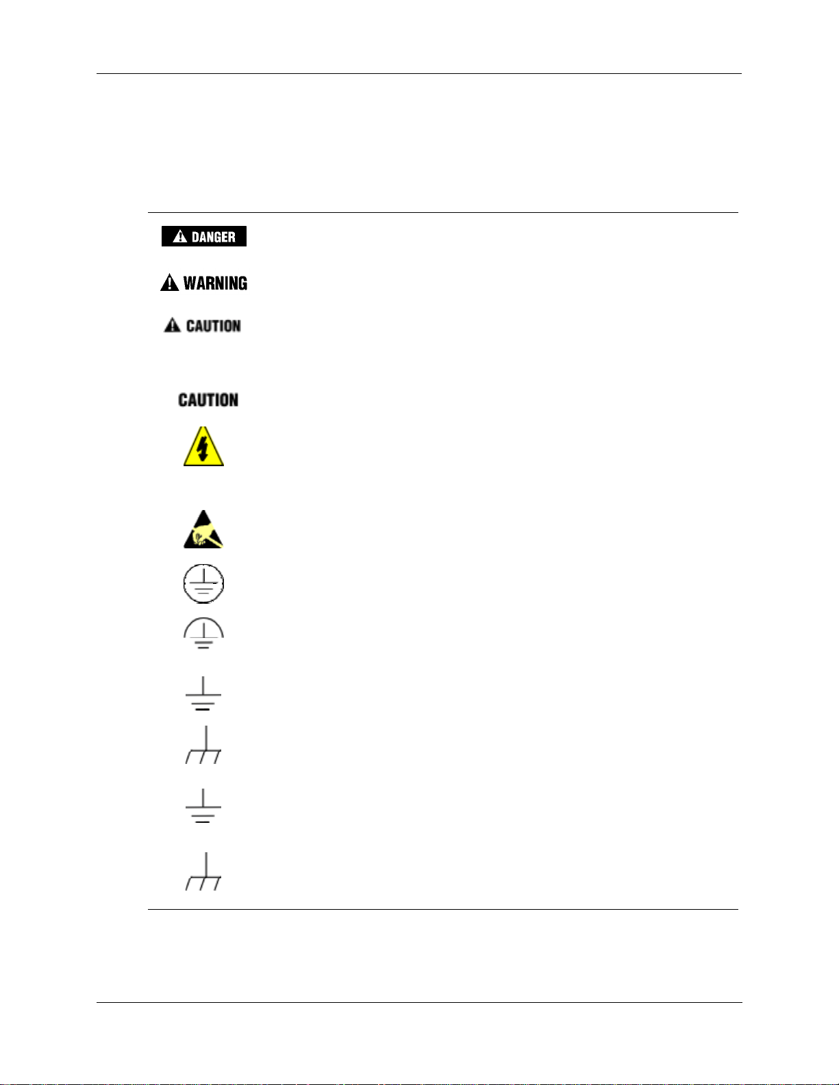
Symbol Definition
This DANGER symbol indicates an imminently hazardous situation, which,
if not avoided, will result in death or serious injury.
This WARNING symbol indicates a potentially hazardous situation, which, if
not avoided, could result in death or serious injury.
This CAUTION symbol may be present on Control Product instrumentation
and literature. If present on a product, the user must consult the
appropriate part of the accompanying product literature for more
information.
This CAUTION symbol indicates a potentially hazardous situation, which, if
not avoided, may result in property damage.
WARNING
PERSONAL INJURY: Risk of electrical shock. This symbol warns the user of a
potential shock hazard where HAZARDOUS LIVE voltages greater than 30 Vrms,
42.4 Vpeak, or 60 Vdc may be accessible. Failure to comply with these
instructions could result in death or serious injury.
ATTENTION, Electrostatic Discharge (ESD) hazards. Observe precautions for
handling electrostatic sensitive devices
Protective Earth (PE) terminal. Provided for connection of the protective earth
(green or green/yellow) supply system conductor.
Functional earth terminal. Used for non-safety purposes such as noise immunity
improvement. NOTE: This connection shall be bonded to protective earth at the
source of supply in accordance with national local electrical code requirements.
Earth Ground. Functional earth connection. NOTE: This connection shall be bonded
to Protective earth at the source of supply in accordance with national and local
electrical code requirements.
Chassis Ground. Identifies a connection to the chassis or frame of the equipment
shall be bonded to Protective Earth at the source of supply in accordance with
national and local electrical code requir eme nts.
iv UMC800 Controller Installation and User Guide Release F
4/01
Page 5

Contents
Introduction.............................................................................................1
Purpose........................................................................................................................1
UMC800 Controller ......................................................................................................2
CE Conformity (Europe)...............................................................................................2
UMC800 Overview.................................................................................. 3
UMC800 Description....................................................................................................3
Feature Summary.........................................................................................................4
Equipment Identification..........................................................................5
Controller Components ................................................................................................5
Operator Interface........................................................................................................7
Control Builder..............................................................................................................8
Serial Communication Ports.......................................................................................10
Pre-Installation Considerations............................................................. 11
Introduction.................................................................................................................11
Mounting and Wiring.............................................................................15
Site Preparation..........................................................................................................15
Mounting the Controller..............................................................................................16
Plug-in Module Locations...........................................................................................18
Signal Wiring..............................................................................................................23
Wiring Communication Links......................................................................................36
Remote Access..........................................................................................................44
Power Supply Wiring..................................................................................................51
Operation..............................................................................................52
Power Up / Power Down............................................................................................52
Operational Modes and Controls ...............................................................................53
File Downloading........................................................................................................56
Code Download..........................................................................................................57
Warm Start / Cold Start ..............................................................................................58
Status Indicators.........................................................................................................59
RS 485 Port Configuration (Communication Board Option) ......................................61
Release F UMC800 Controller Installation and User Guide v
4/01
Page 6

Maintenance .........................................................................................63
Overview ....................................................................................................................63
Routine Maintenance .................................................................................................64
Controller Calibration .................................................................................................65
Replacement Procedures...........................................................................................70
Diagnostics and Troubleshooting..........................................................79
Overview ....................................................................................................................79
Controller Diagnostics ................................................................................................79
Fault Detection and Troubleclearing..........................................................................81
Parts List...............................................................................................91
UMC800 Controller ....................................................................................................91
Specifications........................................................................................93
Introduction.................................................................................................................93
Controller Design........................................................................................................93
I/O Module Configuration...........................................................................................93
Design........................................................................................................................97
Environmental and Operating Conditions ..................................................................99
PV Inputs..................................................................................................................100
Multilanguage Safety Sheets
Service Centers
vi UMC800 Controller Installation and User Guide Release F
4/01
Page 7

Tables
Table 1 Controller plug-in I/O module types................................................................................................................6
Table 2 Communication port descriptions..................................................................................................................10
Table 3 Operating limits.............................................................................................................................................11
Table 4 Permissible wiring bundles............................................................................................................................ 13
Table 5 Power supply input requirements...................................................................................................................16
Table 6 I/O module identification...............................................................................................................................19
Table 7 I/O module installation limitations................................................................................................................20
Table 8 I/O module identification record....................................................................................................................22
Table 9 Universal analog input module specifications...............................................................................................25
Table 10 Summary of communication link connections to controller........................................................................37
Table 11 Configuration connector pinouts..................................................................................................................37
Table 12 Null modem cable construction...................................................................................................................38
Table 13 Operator interface connector pinouts...........................................................................................................40
Table 14 Power supply wiring....................................................................................................................................51
Table 15 Controller mode switch summary................................................................................................................55
Table 16 Controller downloading summary...............................................................................................................56
Table 17 Scan rates per inputs configured ..................................................................................... .............................58
Table 18 Controller status LEDs.................................................................................................................................59
Table 19 Controller status LEDs.................................................................................................................................80
Table 20 Details of the diagnostic summary display............................................................................ ......................81
Table 21 Details of the I/O module diagnostics display.............................................................................................87
Table 22 Controller modem troubleshooting..............................................................................................................89
Release F UMC800 Controller Installation and User Guide vii
4/01
Page 8

Figures
Figure 1 UMC800 components.....................................................................................................................................3
Figure 2 UMC800 controller hardware.........................................................................................................................5
Figure 3 551 operator interface.....................................................................................................................................7
Figure 4 552 operator interface.....................................................................................................................................7
Figure 5 1041 operator interface...................................................................................................................................7
Figure 6 Typical Control Builder graphic display ........................................................................................................8
Figure 7 UMC800 controller enclosure......................................................................................................................15
Figure 8 UMC800 controller enclosure dimensions...................................................................................................17
Figure 9 UMC800 controller plug-in slots..................................................................................................................18
Figure 10 I/O module PWA and terminal...................................................................................................................19
Figure 11 I/O module terminal block (all except 16 point DI) ...................................................................................23
Figure 12 Field wiring shield termination...................................................................................................................24
Figure 13 AI module terminal block connections.......................................................................................................25
Figure 14 Recommended wiring for one pH sensor input..........................................................................................26
Figure 15 AO module terminal block connections.....................................................................................................27
Figure 16 DI module terminal block connections.......................................................................................................29
Figure 17 DO module terminal block connections.....................................................................................................30
Figure 18 DO module relay contact setting................................................................................................................31
Figure 19 PI/FI module terminal block connections....................................................................................................32
Figure 20 PI/FI Module Input Filter Cutoff Frequency setting...................................................................................33
Figure 21 Pulse / Frequency Input Connections..........................................................................................................33
Figure 22 Pulse / Frequency card digital output connections ......................................................................................35
Figure 23 Communication port connectors.................................................................................................................36
Figure 24 Ferrite clamp installation............................................................................................................................39
Figure 25 Terminal connections.................................................................................................................................41
Figure 26 COMM A and B port wiring (2-wire and 4-wire)......................................................................................42
Figure 27 RS 485 port wiring (2 wire)........................................................................................................................43
Figure 28 Power supply terminal connections............................................................................................................51
Figure 29 Controller mode switch location.................................................................................................................54
Figure 30 Controller status LEDs...............................................................................................................................60
Figure 31 COMM A and B ports on CPU module......................................................................................................61
Figure 32 Controller components that contain calibration values...............................................................................66
Figure 33 AI module terminal block...........................................................................................................................68
Figure 34 AO module jumper ST1.............................................................................................................................69
Figure 35 Controller components and location...........................................................................................................70
Figure 36 Power supply fuse and CPU battery location.............................................................................................72
Figure 37 I/O module terminal blocks (not shown: 16 point DI)................................................................................75
viii UMC800 Controller Installation and User Guide Release F
4/01
Page 9

Purpose
This Installation and User guide assists in the installation, start up, operation, maintenance and
troubleshooting of the UMC800 Controller.
The information in this guide is organized as follows:
Introduction
Purpose
Introduction
Topic Description Page
UMC800 Overview
Equipment Identification A high-level physical and functional description of the
Pre-installation
Considerations
Mounting and Wiring Information and procedures to successfully install the
Installation Checkout and
Power Up
Operation Power up and power down routines, operational modes and
Maintenance Procedures are given covering routine maint enan ce and the
Diagnostics and
Troubleshooting
Provides a concise description of the UMC800 control
system, its applications, architecture and its features
UMC800 components
Lists a number of things to consider when planning the
controller installation. Environmental factors as well as
methods to minimize interference are dis cu sse d.
UMC800 controller and its components. Interconnecting
wiring to other UMC800 components is also covered.
Provides a checklist to complete before power up. Covers
power up procedure.
controls, software download routines, warm and cold start
routines, Status LEDs, and scan rates are covered in this
section.
replacement of controller componen ts. Infor mat ion on I/O
module calibration is presented.
Provides description of controller status and error conditions.
Provides corrective actions necessary to clear fault
conditions.
3
5
11
15
44
52
63
79
Parts List A list of replacement parts for the controller. 91
Specifications
Supplemental Installation
Information
Release F UMC800 Controller Installation and User Guide 1
4/01
Summary of electrical, physical, environmental and
performance specification s.
Provides helpful information for installing digital equipment in
severe electrical noise environments.
Refer to document 51-52-05-01 How to Apply Digital
Instrumentation in Severe Electrical Noise Environments.
93
––
Page 10

Introduction
UMC800 Controller
UMC800 Controller
The UMC800 is industrial process control equipment that must be mounted. The wiring terminals must be
enclosed within a panel.
CE Conformity (Europe)
This product is in conformity with the protection requirements of the following European Council
Directives: 73/23/EEC, the Low Voltage Directive, and 89/336/EEC, the EMC Directive. Conformity of
this product with any other “CE Mark” Directive(s) shall not be assumed.
Deviation from the installation conditions specified in this manual, and the following special conditions,
may invalidate this product’s conformity with the Low Voltage and EMC Directives.
ATTENTION
The emission limits of EN 50081-2 are designed to provide reasonable protection against
harmful interference when this equipment is operated in an industrial environment. Operation
of this equipment in a residential area may cause harmful interference. This equipment
generates, uses, and can radiate radio frequency energy and may cause interference to radio
and television reception when the equipment is used closer than 30 meters (98 feet) to the
antenna(e). In special cases, when highly susceptible apparatus is used in close proximity, the
user may have to employ additional mitigating measures to further reduce the electromagnetic
emissions of this equipment.
2 UMC800 Controller Installation and User Guide Releas e F
4/01
Page 11
UMC800 Description
The Universal Multiloop Controller (UMC800) is a modular controller designed to address the analog and
digital control requirements of small unit processes. With up to 16 analog control loops, four setpoint
programmers, and an extensive assortment of analog and digital control algorithms, the UMC800 is an
ideal control solution for furnaces, environmental chambers, ovens, reactors, cookers, freeze dryers,
extruders, and other processes with similar control requirements.
Accommodating up to 64 universal analog inputs, 16 analog outputs, and 96 digital inputs/outputs, the
UMC800 provides the appropriate balance of input and output hardware for these smaller unit processes.
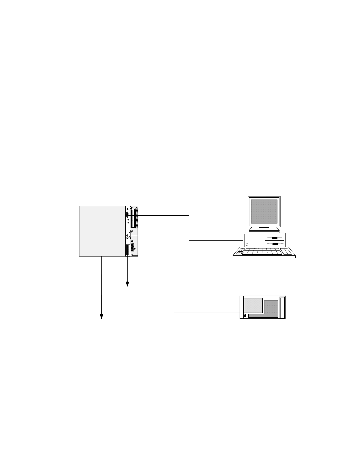
The UMC800 uses separate hardware for control functions and operator interface functions to provide
greater installation flexibility. See Figure 1. The controller incorporates card slots capable of supporting up
to 16 input and output modules that can be mixed to satisfy the hardware requirements of a specific
application. The operator interface uses a color graphic LCD display to provide a variety of display
presentations for viewing control loops, setpoint programs, and other analog and digital status.
UMC800 Overview
UMC800 Description
UMC800 Overview
PC or Laptop with
Control Buil der
Conf igura tion Sof twa re,
On -Li n e H el p an d
User Utility So ftware
UMC800
Co ntroller
OFFLINE
RUN
PROG RAM
CONFIGURATI ON
POWER
LoBA T
FORC E
RUN
Replac e batte ry with T adiran T L510 1/S
See users gui de for ins truct ions.
only. Use of another battery m ay
present a ris k of fir e or expl osio n.
_
DISP LAY
100 - 230 V ~
BAT
50 / 60 Hz
100 VA MAX.
F 3,15 A T
L1
L2 /
N
COMM B COMM A
RS 485 Serial
Communications with
Modbus RTU Protocol
(Option al)
To Field
Devices
Operator Int erface
Figure 1 UMC800 components
A separate “Control Builder” configuration software program is used for system configuration that
operates on a Windows 95- or NT-based PC. The software program uses graphic symbols and line drawing
connections to create custom control strategies. Menus are provided in the software to allow selection of
screens for the operator interface and to customize screen access methods and operator keys. Completed
configurations are loaded into the control system using a dedicated communications port in the controller,
or optionally, via floppy disk. A separate User Utility software program (also running on a PC) is used to
create, edit, save, open and download individual recipe, profile and data storage files. Calibration of the
analog input and output modules can be performed through this utility program. A modem connection
Release F UMC800 Controller Installation and User Guide 3
4/01
Page 12

UMC800 Overview
Feature Summary
through the Configuration port allows remote access to the controller via the Control Builder and User
Utility programs. This will enable trouble shooting, configuration c hanges and firmware upgrade.
The optional communications board adds two bi-directional, multi-drop RS 485 serial communication
interfaces to the controller CPU module. The COMM A port uses Modbus RTU protocol and is a
master/slave link allowing up to 31 controllers to be connected to a single host computer. The computer
initiates all communication. COMM B port allows the controller to operate as a master device to up to 16
slave Modbus compatible devices. Data transferred through this port is integrated into the user’s control
strategy through read and write function blocks. Applications might include writing controller data (set
points, process variables, etc.) to a strip chart recorder to produce a hard copy of process performance, or to
read data from other controllers.
Feature Summary
• Up to 16 control loops, including:
− Proportional Integral Derivative (PID),
− ON/OFF,
− Three Position Step Control (TP SC) , and
− Carbon Potential.
• Auto-tuning for each control loop
• Up to 64 Universal Analog Inputs
• Up to 16 Analog Outputs
• Up to 96 Digital Inputs/Outputs
• Up to 50 Recipes with up to 50 variables each
• Up to 4 Setpoint Programmers, 3500 total segments
• Setpoint Profile and Recipe storage, up to 70 programs
• Setpoint Scheduler, 10 stored schedules
• Function Block Graphic Configuration with up to 250 blocks
• Large assortment of algorithms for combination of analog and logic functions
• Extensive Alarm and Event monitoring
• Operator interface with a selection of graphic displays
• Carbon Potential, Dewpoint and Relative Humidity Co ntro l
• Optional 3-1/2” floppy disk drive for data archiving, setpoint program and recipe storage
• Universal Power (100 to 240 Vac or Vdc) or 24 VA RH)
• UL, CE, and CSA approved, Y2K compliant C/DC (optional)
• Industrial Operating Range (0 °C to 55 °C, 10 % to 90 %
• UL, CE, and CSA Approved, Y2K compliant
4 UMC800 Controller Installation and User Guide Releas e F
4/01
Page 13
Equipment Identification
Controller Components
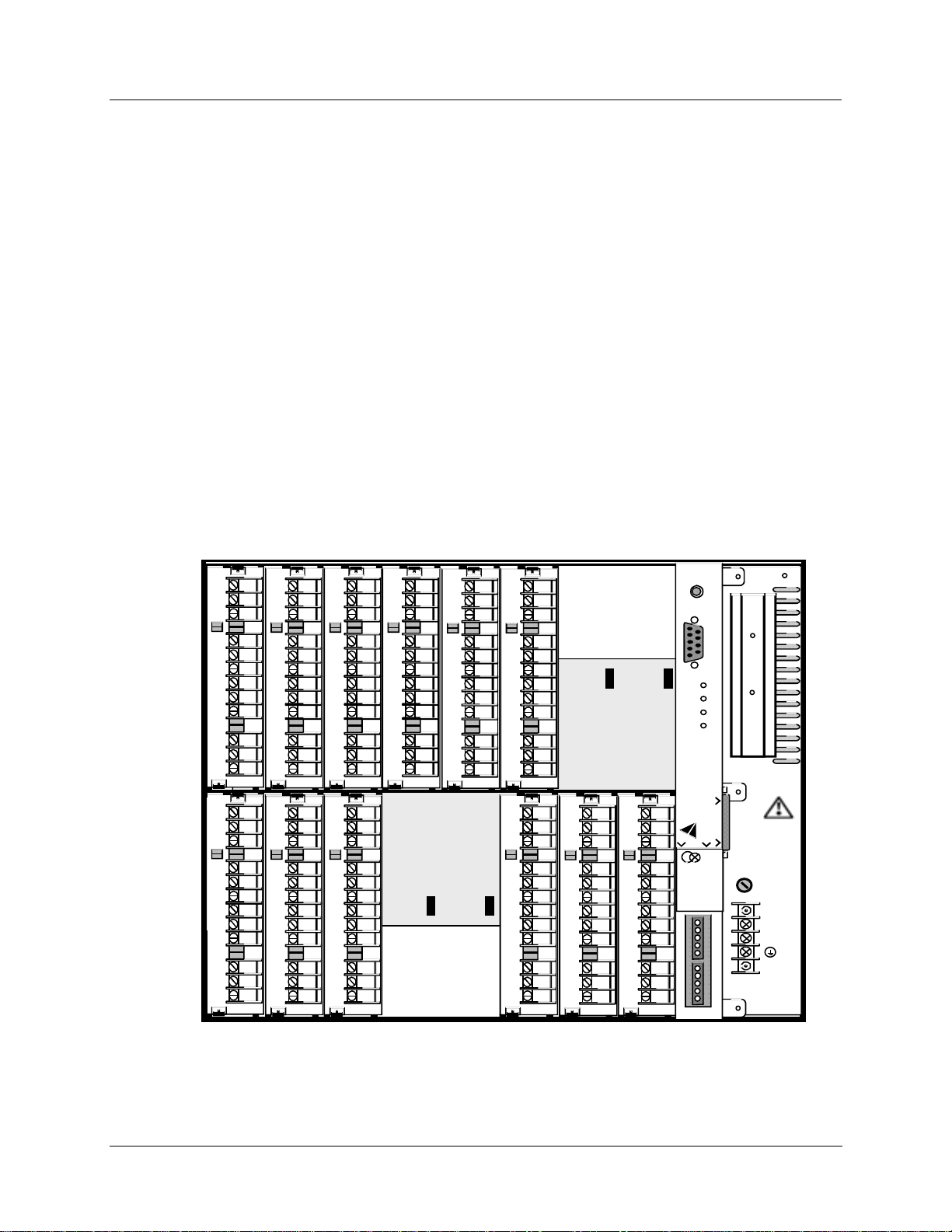
Enclosure
The UMC800 controller illustrated in Figure 2 consists of a single metal enclosure that houses the
following controller components:
• Power supply module that plugs into the controller common backplane.
• CPU module with two serial communications ports. An optional communications board provides two
RS485 serial communication ports (slave and master) that support Modbus® RTU protocol.
• Backplane assembly capable of supporting up to 16 input or output modules.
• Various types of I/O processing modules that plug into the common backplane.
• Removable terminal blocks that connect the I/O modules with the field wiring.
Equipment Identification
Controller Components
• Battery back-up power for RAM and real time clock in the event of power interruption.
12
11
10
9
8
7
6
5
4
3
2
1
12
11
10
9
8
7
6
5
4
3
2
1
12
11
10
9
8
7
6
5
4
3
2
1
12
11
10
9
8
7
6
5
4
3
2
1
12
11
10
9
8
7
6
5
4
3
2
1
12
11
10
9
8
7
6
5
4
3
2
1
12
11
10
9
8
7
6
5
4
3
2
1
12
11
10
9
8
7
6
5
4
3
2
1
12
11
10
9
8
7
6
5
4
3
2
1
12
11
10
9
8
7
6
5
4
3
2
1
12
11
10
9
8
7
6
5
4
3
2
1
12
11
10
9
8
7
6
5
4
3
2
1
OFFLINE
RUN
PROGRAM
POWER
LoBAT
FORCE
RUN
Replace battery with Tadiran TL5101/S
only. Use of another battery may
present a risk of fire or explosion.
See user’s guide for instructions.
BAT
CONFIGURATION
_
100 - 240 V ~
DISPLAY
50 / 60 Hz
100 VA MAX.
COMM B COMM A
F 3,15 A T
250V
L1
L2 / N
Figure 2 UMC800 controller hardware
Release F UMC800 Controller Installation and User Guide 5
4/01
Page 14

Equipment Identification
Controller Components
I/O modules
Eleven different module types can be installed in the controller to support both analog and digital inputs
and outputs of various types and signal levels. The signal type and I/O capacity for each module type is
indicated in Table 1.
Table 1 Controller plug-in I/O module types
Module Type Signal Types Maximum
I/O
Universal Analog Inputs (AI) mV, V, mA, T/C, RTD, Ohms 64 4 16
Analog Outputs (AO) 0 mA to 20 mA 16 4 4
Digital Inputs (DI) - 4 types:
AC 100/240 Vac 96 6 16
DC 24 Vdc 96 6 16
Logic Dry contacts
(5 mA - 5 Vdc)
16 point Dry contacts 48 16 3
Digital Outputs (DO) - 4 types:
AC 100/240 Vac 96 6 16
AC
High current outputs
DC 24 Vdc 96 6 16
Relay SPST normally open (NO) or
Pulse Input/Frequency Input 24 Vdc 64 4 16
100/240 Vac
With:
2 outputs rated @ 2 A
4 outputs rated @ 0.5 A
normally closed (NC) contact.
(User configurable)
96 6 16
12 2 12
60 6 10
I/O per
card
Maximum no.
of cards
pH Power Module ± 15 Vdc 8 4 2
NOTE: Total combined digital I/O is 96 points.
Control architecture
The UMC800 uses a function block configuration architecture to develop control strategies for both analog
and digital operations. A function block may represent a physical input or output, a group of physical inputs
or outputs, an internal calculation, or an internal function such as a PID algorithm. More than 70 standard
UMC800 function block algorithm types are available for configuring analog and logic functions.
Typically, a function block algorithm type may be used any number of times up to the limit of 250 blocks.
Some of these with specific limitations are:
• Control loops (i.e., PID, ON/OFF, TPSC, and Carbon potential)—eight or sixteen maximum
• Setpoint programmer and associated support blocks—four maximu m
• Setpoint Scheduler and associated support blocks—one maximum
• Time proportioning output blocks—sixteen maximum
• Pushbutton blocks—four maximu m
• 4 Selector Switch blocks—four maximum
• Modbus Slave blocks—sixteen maximum
6 UMC800 Controller Installation and User Guide Releas e F
4/01
Page 15
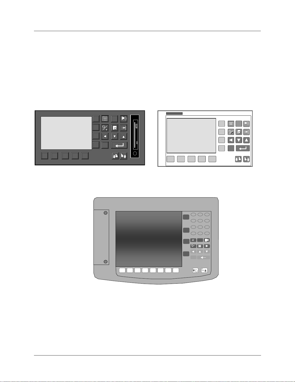
Operator Interface
The UMC800 operator interface (Figure 3, Figure 4, and Figure 5) provides a graphic LCD display and a
monoplaner keyboard to allow operator access to all controller functions. The operator interface becomes
operational once a valid database is configured in the controller. Modification and customization of the
operator interface is performed using Control Builder software. With the software, data points can be
identified (tagged) using eight character names. Once named, these data points may be accessed by the
operator interface using a standard set of display formats and a predefined menu hierarchy. Customized
display access and the assignment of selected displays to keyboard buttons may be developed using Control
Builder software. Selected displays such as bargraphs, trends, and overview displays will require the user to
specify the individual data points to be represented on the display.
Equipment Identification
Operator Interface
F1
F2
F3
ESC
F4
1 2 3 4 5
Figure 3 551 operator interface
?
ALARM
Honeywell
F1
F2
F3
F4
KB
1 2 3 4 5
ESC
?
ALARM
Figure 4 552 operator interface
7 8 9
F1
4 5 6
1 2 3
F2
0 . -
F3
F4
?
ESC
1 2 3 4 5 6 7 8
Figure 5 1041 operator interface
Release F UMC800 Controller Installation and User Guide 7
4/01
Page 16
Equipment Identification
Control Builder
Control Builder
All controller and operator interface configuration is performed using Control Builder software on a
separate PC operating with Windows
TM
95 or WindowsTM NT 4.0. All configuration is performed off-line
(computer disconnected from the controller and operator interface). The configuration is downloaded in a
separate operation as a complete file through a dedicated RS-232 communication port on the controller.
Once a configuration is installed into the controller and operator interface, the Control Builder software
may be used to monitor areas of the configuration to verify proper op eration. Co ntro ller configuration
development is performed using "Drag and Drop” techniques for positioning graphic icons on a CRT
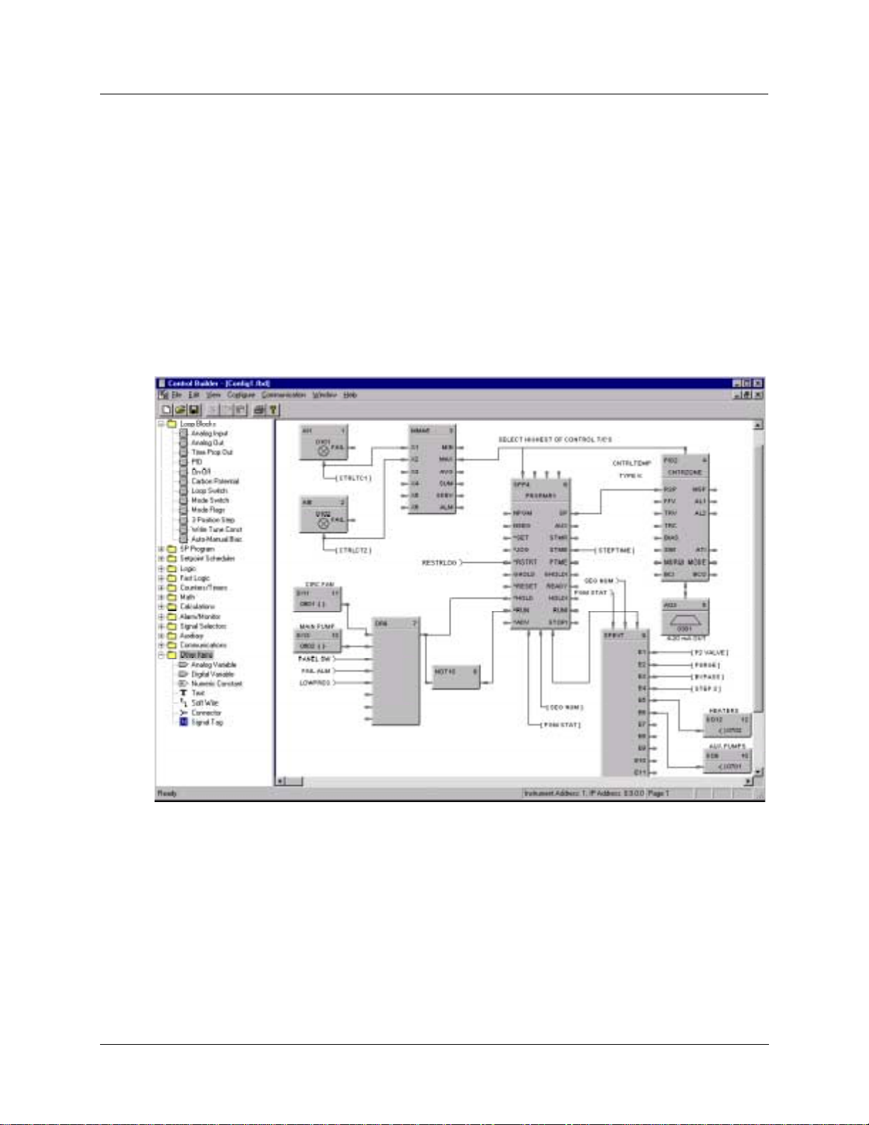
display from a list of available functions. See Figure 6. Signal flow connectio ns from icon to icon complete
the controller configuration. The Control Builder software will create a graphic dia gram 1 page high by 20
pages wide. The completed diagram may be printed on 20 pages of 8.5" x 11.5" paper. Each configuration
is saved as a single PC file. Multiple files may be saved o n the PC. The Control Builder can concurrently
open multiple configuration files.
Figure 6 Typical Control Builder graphic display
8 UMC800 Controller Installation and User Guide Releas e F
4/01
Page 17

Completed configurations may also be saved on 3.5" floppy disk and loaded into the controller and
operator interface through an optional 3.5" floppy disk drive, eliminating the need for a direct connection of
a PC to the controller.
Each analog signal flow line of the configuration may be labeled with an 8-character name, 4-character
engineering unit definition, and may have a decimal point location specified. Digital signal lines may be
identified with an 8-character name and 6-character ON and OFF label.
Signal tag descriptions are used by the operator interface to present on-line status.
Control Builder software may also be used to reconstruct a n existing controller configuration by uploading
the configuration from the controller for maintenance or diagnostic purposes.
Operator Interface configuration is performed by identifying values to show on predefined display
templates and defining the display access buttons.
Control Builder on-line help
Equipment Identification
Control Builder
The on-line help system provides a convenient and quick way to look up any task you are performing in the
Control Builder program. This Windows
any time you request help, a help topic appears that pertains to where you are in the program. For example,
if you are focused on a particular program window, you will get a help topic that describes that window. If
you are in a particular dialog box or entry field, you will get a help topic that describes that dialog box or
entry field.
Within a help window there may be hotspots which are shown as highlighted text. If you cl ick on the
highlighted text, a pop-up box with a definition or a separate window of information that corresponds to the
designated hotspot topic will appear.
The help menu, which is accessible from any main menu, can be used to display an index and the contents
of all help topics in the program.
A right-click on a Function Block provides topic help for that block.
User utility
A separate user utility program is available, which is a windows-based program, and is designed for enduser administration tasks of the UMC800. This utility allows you to create, edit, and download recipes,
setpoint profiles, setpoint schedules and data storage files. Controller files can be downloaded and uploaded
at the PC. Using the communications menu and dialog boxes, communications parameters can be setup to
match your PC communications settings. A loopback test can be initiated to verify communications
between your PC and the controller, and an error summary provides data for troubleshooting
communications problems. The maintenance menu provides access to controller diagnostic data and allows
users to initiate calibration of selected I/O modules.
help system offers context-sensiti ve he lp which means that at
Release F UMC800 Controller Installation and User Guide 9
4/01
Page 18

Equipment Identification
Serial Communication Ports
Serial Communication Ports
The controller contains dedicated serial ports for external communications. These are described in Table 2.
Table 2 Communication port descriptions
Communication
Port
(on CPU Module)
Configuration
Display
COMM A
(with optional
communication
board)
COMM B
(with optional
communication
board)
Description
Configuration Port - This RS232 port is a dedicated connection for
communications with a PC running the Control Builder configuration program .
The communications link layer protocol is proprietary. Communication is
through a null modem cable or through a modem.
This RS 422 port is a dedicated connection for communications with the
operator interface. Separate power leads included in the cable also supply
power to the operator interface. The communications link layer is proprietary
and not intended for external use.
RS 485 Serial communication port using Modbus RTU protocol. This port allows
the controller to operate as a slave device on a multi-drop bus with up to 31
other UMC800 controllers and Modbus compatible devices. A PC host can be
connected to the bus and used for controller configuration and monitoring tasks.
RS 485 Serial communication port using Modbus RTU protocol. This port allows
the controller to operate as a master device to up to 16 slave Modbus
compatible devices. Data transferred through this port is integrated into the
user’s control strategy through read and write function blocks.
10 UMC800 Controller Installati on and User Guide Release F
4/01
Page 19

Introduction
Installation of the controller consists of mounting and wiring the controller according to the guidelines
given in this section. The controller is industrial control equipment that must be panel mounted within an
enclosure. The wiring terminals must be enclosed within the enclosure.
Read the pre-installation information, check the model number interp r etation [Controller model number
(page 21)], and become familiar with your model selections, then proceed with installation.
While the UMC800 has been designed for use in most industrial environments, there are certain
requirements that should be considered regarding installation and wiring to ensure optimum performance.
Many of the problems associated with electronic control equipment can be traced to the primary ac power
system. Disturbance, such as electrical noise, power interruptions, and lightning, must be factored into the
planning of the primary power system so the control equip ment will perform satisfactorily and
continuously.
In addition to the precaution of the separation of signal and power wiring in separate conduits, this section
suggests some other measures that can be taken to minimize the effects of electromagnetic interference
(EMI) and radio frequency interference (RFI), voltage surges and static electricity.
Pre-Installation Considerations
Introduction
Pre-Installation Considerations
Operating limits
We recommend that you review and adhere to the operating limits listed in Table 3 when you install the
controller.
Ambient Temperature
Relative Humidity 10 % to 90 % RH at 40 °C (104 °F)
Vibration
Mechanical Shock
Power
Power Consumption 100 VA Maximum
Table 3 Operating limits
Condition Specifications
32 °F to 131 °F (0 °C to 55 °C)
Frequency
Acceleration
Acceleration
Duration
Voltage
Frequency (Hz)
14 Hz to 250 Hz
1 g
1 g
30 ms
100 V to 240 V (24 V optional)
50/60 Hz or dc
Release F UMC800 Controller Installation and User Guide 11
4/01
Page 20

Pre-Installation Considerations
Introduction
Electrical considerations
The controller is considered “open equipment” per EN 61010-1, Safety Requirements for Electrical
Equipment for Measurement, Control, and Laboratory Use, Part 1: General Requirements. Conformity with
72/23/EEC, the Low Voltage Directive requires the user to provide adequate protection against a shock
hazard. The user shall install this controller in an enclosure that limits OPERATOR access to the rear
terminals.
Controller grounding
PROTECTIVE BONDING (grounding) of this controller and the enclosure in which it is installed shall be
in accordance with National Electrical Code (ANSI/NFPA 70) and local electrical codes.
Taking electrical noise precautions
Electrical noise is composed of unabated electrical signals that produce undesirable effects in
measurements and control circuits.
Digital equipment is especially sensitive to the effects of electrical noise. You should use the following
methods to reduce these effects:
• Supplementary bonding of the controller enclosure to a local ground, using a No. 12 (4 mm
conductor, is recommended. This may help minimize electrical noise and transients that may adversely
affect the system.
2
) copper
• Separate External Wiring - separate connecting wires into bundles (see Table 4) and route the individual
bundles through separate conduits or metal trays.
• Use shielded twisted pair cables for all Analog I/O, Process Variable, RTD, Thermocouple, dc millivolt,
low level signal, 4-20 mA, Digital I/O, and computer interface circuits.
• Use suppression devices for additional noise protection. You may want to add suppression devices at the
external source. Appropriate suppression devices are commercially available.
• Refer to document 51-52-05-01 How to Apply Digital Instrumentation in Severe Electrical Noise
Environments for additional installation guidance.
12 UMC800 Controller Installati on and User Guide Release F
4/01
Page 21

Permissible wire bundling
Table 4 shows which wire functions should be bundled together.
Bundle No. Wire Functions
Pre-Installation Considerations
Introduction
Table 4 Permissible wiring bundles
1
2
3
• Line power wiring
• Earth ground wiring
• Control relay output wiring
• Line voltage alarm wiring
Analog signal wire, such as:
• Input signal wire (thermocouple, 4 mA to 20 mA, etc.)
• 4-20 mA output signal wiring
• Slidewire feedback circuit wiring
• Digital input signals
• Communications
• Low voltage alarm relay output wiring
• Low voltage wiring to solid state type control circuits
Release F UMC800 Controller Installation and User Guide 13
4/01
Page 22

Pre-Installation Considerations
Introduction
14 UMC800 Controller Installati on and User Guide Release F
4/01
Page 23
Site Preparation
The UMC800 must be mounted within an enclosure. Hardware is provided to surface mount the controller
to a panel or other suitable surface. Be sure that there is sufficient clearance for mounting the controller
enclosure and the external wiring.
UMC enclosure and components
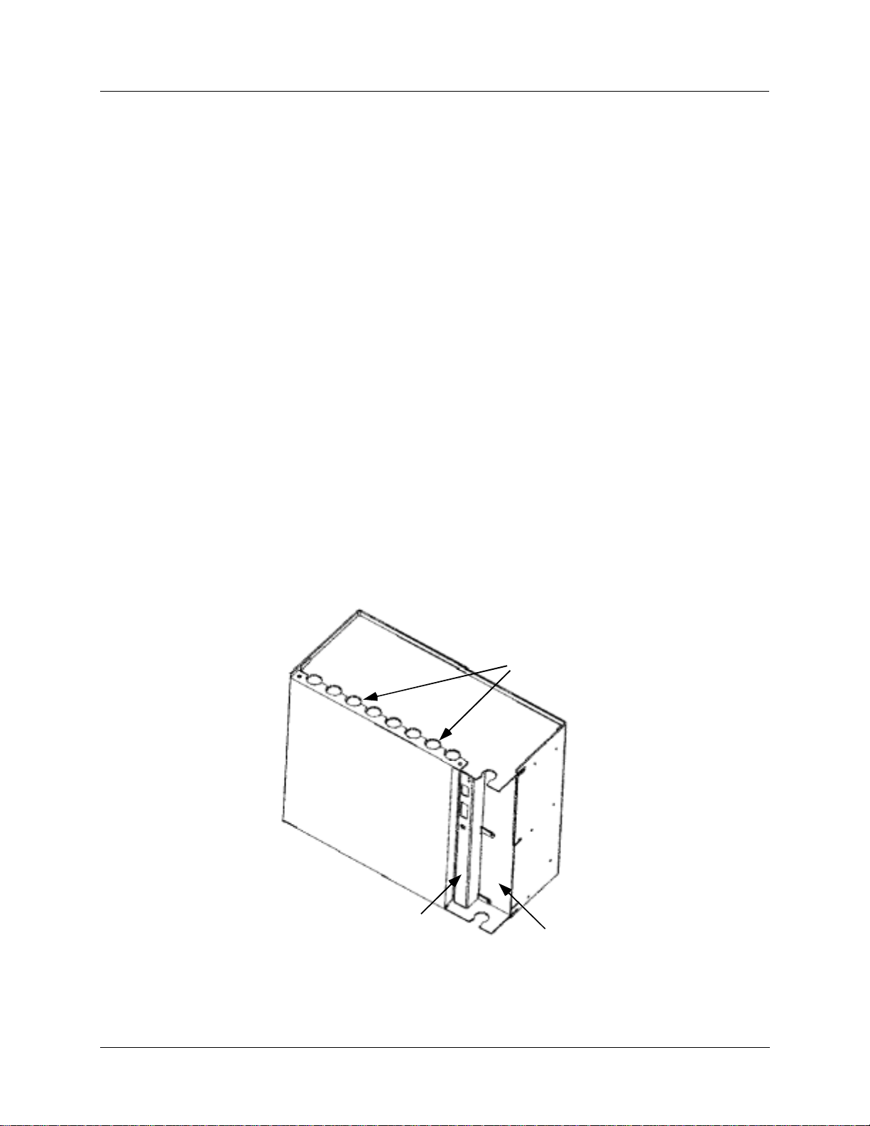
The controller enclosure houses all circuit assemblies of the UMC controller. See Figure 7. The power
supply and CPU are modules that plug into slots on the right hand side of the enclosure. Both modules have
metal covers on the front where indicators, switches and connectors are located. All external connections to
the power supply and CPU are made on the front panels of these modules.
A front cover can be removed by two screws to access the I/O modules. There are two rows of card guides
to accommodate up to 16 plug-in I/O modules. External signal wiring to field devices are made with
removable terminal blocks that attach to the front of each I/O module. Optional terminal strips can be used
to provide shield termination of field wiring.
Mounting and Wiring
Site Preparation
Mounting and Wiring
Power supply, CPU and I/O modules are connected through a common backplane within the enclosure. All
external wiring for power supply and I/O modules are brought out through rubber grommets located at the
top and bottom of the enclosure. The CPU features two connections for external communications. One
provides a cable connection to a PC for configuration and database file management; the other connection
accommodates a cable to the operator interface. An optional communication board provides two RS 485
serial communications ports (slave and master) using Modbus RTU protocol.
External Wiring
Access Holes
Front
Cover
CPU Module
Power Supply
Figure 7 UMC800 controller enclosure
Release F UMC800 Controller Installation and User Guide 15
4/01
Page 24

Mounting and Wiring
Mounting the Controller
Power requirements
The standard supply uses 100/240 Vac or Vdc input ranges for its source. The input requirements are listed
in Table 5. Instructions for wiring the power supply are found in Table 5.
100-240 Vac or dc (+10 % or –15 %) 50/60 Hz or dc 100 VA maximum
24 Vac or dc (optional)
24 Vac (+25 % or –15 %) or
24 Vdc (+50 % or –8% )
Assembling parts
Assemble all parts of the UMC800 along with tools required to mount the UMC800 hardware. You should
have these tools on hand:
• Tool box that includes a center punch and a standard complement of flat blade and Phillips head
screwdrivers as well as box-end and open-end wrenches.
Table 5 Power supply input requirements
Voltage Input Frequency Power Consumption
50/60 Hz or dc 100 VA maximum
• A drill tap and drill with number 9 drill bit for drilling clearance holes as ap plicable.
• Tools for measuring and marking location of clearance holes and cutout on panel as well as cutting a
hole in the panel.
Mounting the Controller
Mounting controller enclosure on a panel
The controller enclosure is made to be surface mounted within an enclosure. The controller can be mounted
so that the power supply is at the righthand side, or the controller can be rotated 90 degrees so that the
power supply is at the top. For either mounting, there must be sufficient space allowed for routing the
external wiring.
Four holes at the back of the enclosure are provided for surface mounting with screws. Use the steps in the
table below to mount the controller enclosure on a panel.
Step Action
1
2
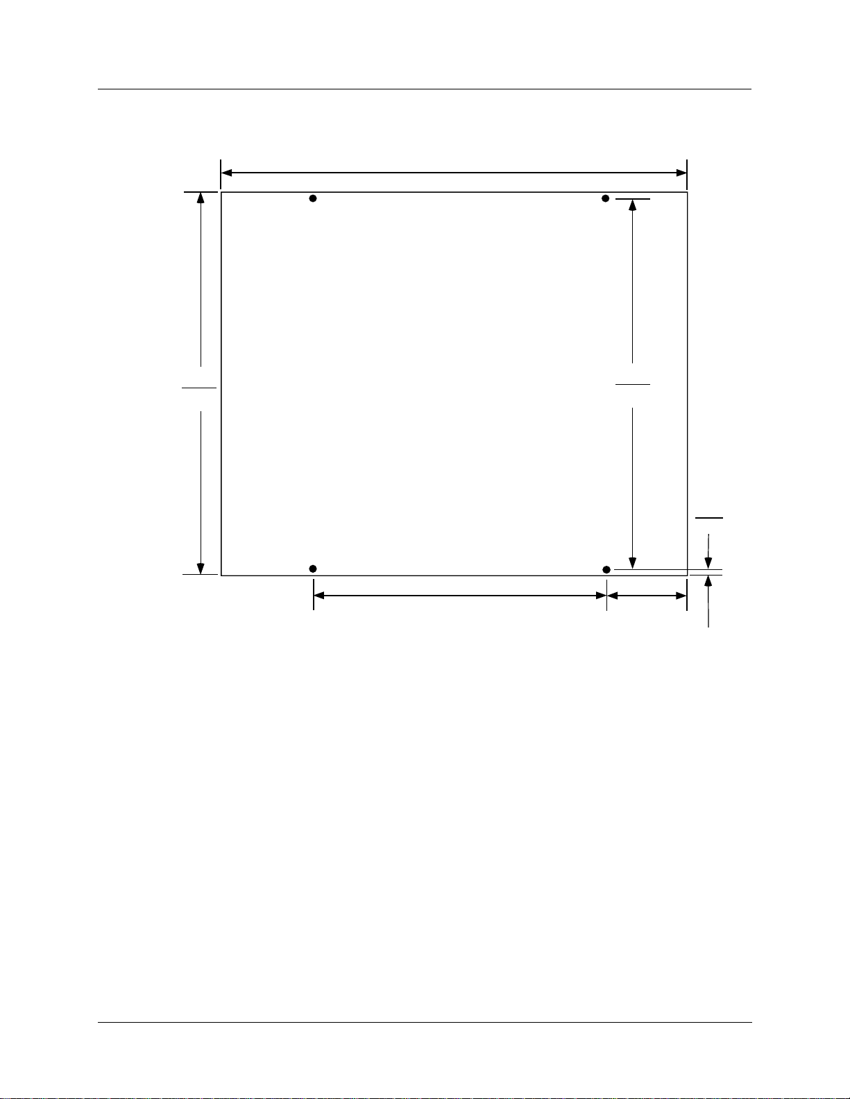
Layout mounting hole patterns on panel according to dimensions shown in Figure 8. Or,
position controller enclosure on panel and use enclosure as a template.
NOTE: Rotate the mounting dimensions 90 degrees to mount the enclosure sideways with
the power supply at the top.
Drill and tap mounting holes for 1/4-20 (or M6) machine screws (supplied by us er).
3
16 UMC800 Controller Installati on and User Guide Release F
Position enclosure on panel so holes in enclosure align with holes in panel. Secure enclosure
to panel with 1/4-20 (or M6) machine screws using external tooth washers.
4/01
Page 25
Enclosure mounting dimensions
Mounting and Wiring
Mounting the Controller
13.027
330.89
11.77
298.96
inches
Dimensions =
millimeters
_________
7.0
177.8
11.37
286.26
0.25
6.35
3.013
76.53
NOTE: Allow 7.0” (178 mm) depth to mounting dimensions for controller enclosure and cabling. To
mount the controller so that t he po wer supply is at the top, rotate the mounting dimensions 90 degrees.
Figure 8 UMC800 controller enclosure dimensions
Release F UMC800 Controller Installation and User Guide 17
4/01
Page 26
Mounting and Wiring
Plug-in Module Locations
Plug-in Module Locations
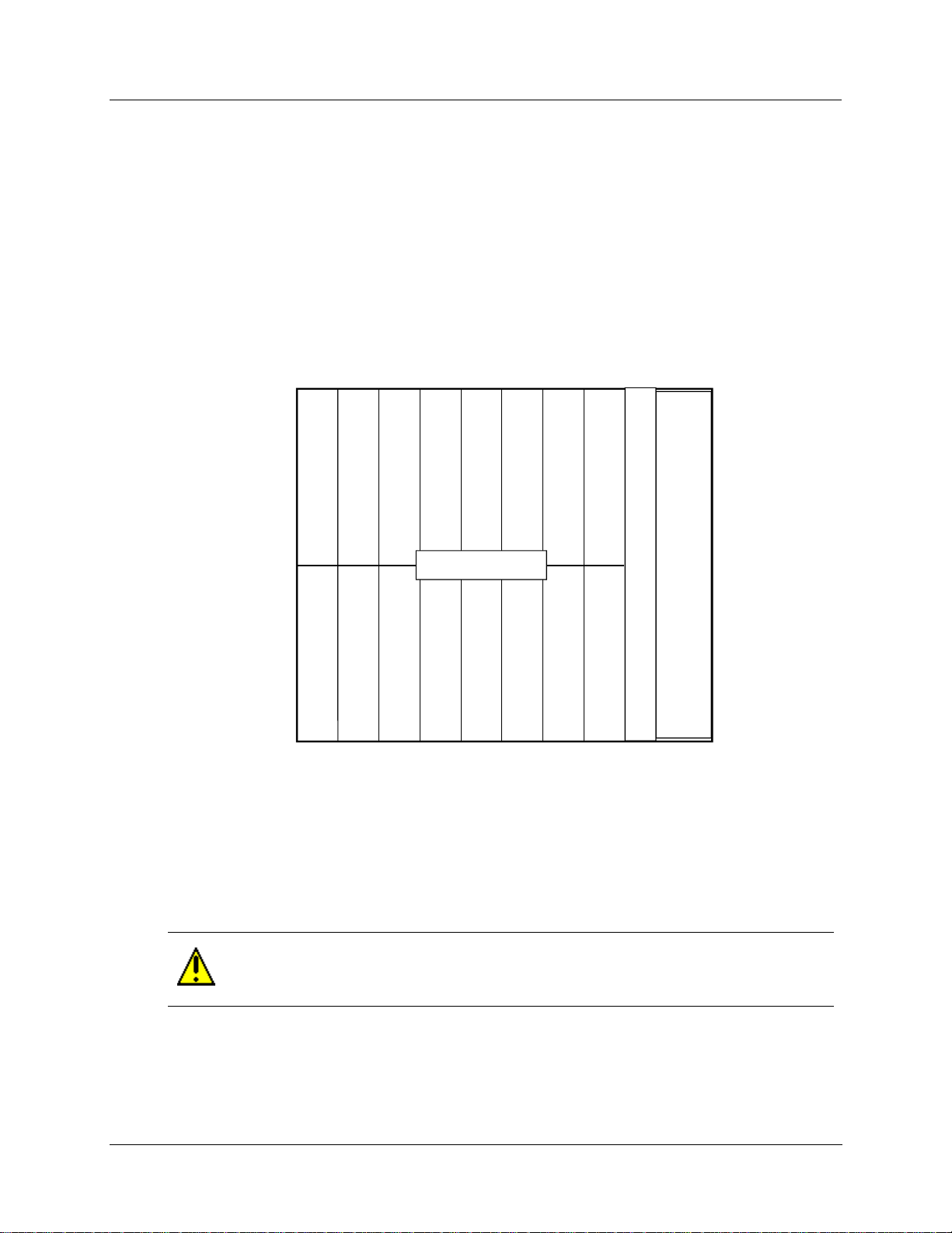
Common backplane
The controller backplane provides common connections for the power supply, CPU and I/O modules. All
modules are installed into the backplane in their assigned slots designated by the controller model number.
[See Controller model number (page 21).] The power supply and CPU occupy the slots on the right side of
the enclosure. See Figure 9. Slots for the I/O modules are numbered from 1 to 16 to be consistent with I/O
address assignment when using the PC control builder software.
Slots 1-8 (left to right) comprise the lower slots.
Slots 9-16 (left to right) comprise the upper slots.
9 10 11 12 13 14 15 16
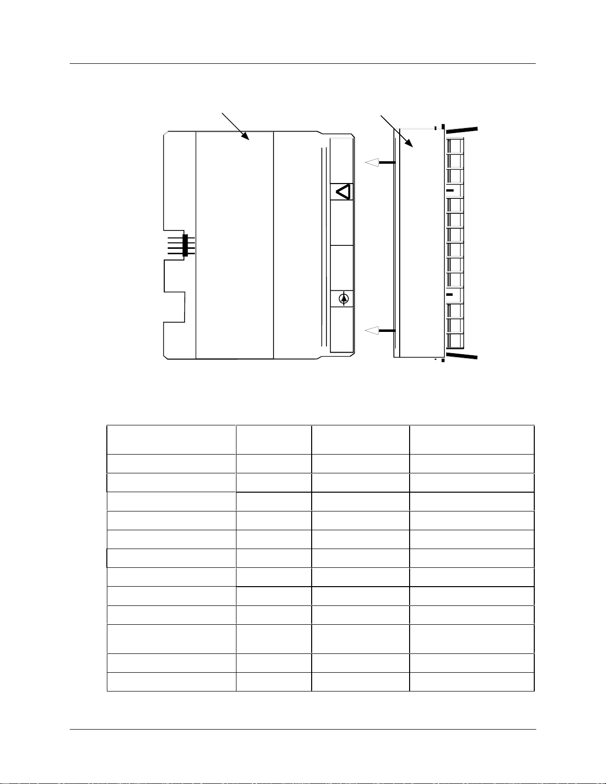
I/O module identification
I/O modules consist of a Printed Wiring Assembly (PWA) and a color-coded terminal block. Each module
type is identified by a number label attached to a colored terminal block. Typically, red terminal blocks
indicate AC voltage inputs and outputs and black terminal blocks i ndicate low voltage modules. See Figure
10 for an example. Module type and terminal block identification are described in Table 6.
CAUTION
Do not switch the terminal boards and I/O module PWAs. The color and number designation
of the terminal boards should match the correct I/O module type.
I/O Module Slots
1 2 3 4 5 6 7 8
Figure 9 UMC800 controller plug-in slots
CPU
Power
Supply
18 UMC800 Controller Installati on and User Guide Release F
4/01
Page 27
Mounting and Wiring
Plug-in Module Locations
I/O Module
PWA
Figure 10 I/O module PWA and terminal
Terminal
Block
+
OUT 4
_
!
+
OUT 3
_
+
OUT 2
_
mA
0-20
+
OUT 1
_
Table 6 I/O module identification
Module Type ID Number
Analog Input (AI) 1 Black 46190305-503
Analog Output (AO) 2 Black 46190314-503
Digital Input (DI) - Logic 3 Black 46190311-503
Digital Input (DI) - DC 4 Black 46190347-501
Digital Input (DI) - AC 5 Red 46190350-501
Digital Input (DI) - 16 point B Orange or Beige 46190353-501
Digital Outputs (DO) - Relay 6 Red 46190308-503
Digital Outputs (DO) - DC 7 Black 46190341-501
Digital Outputs (DO) - AC 8 Red 46190344-501
Digital Outputs (DO) - Higher
A Red 46190344-502
Current AC
± 15 Vdc pH Power Module C Black 51450921-501
Pulse/Frequency Input D Black 46190360-501
Terminal Block
Color
Part Number
Release F UMC800 Controller Installation and User Guide 19
4/01
Page 28

Mounting and Wiring
Plug-in Module Locations
I/O module limits
The controller backplane accommodates I/O module types, subject to the limitations as shown in Table 7.
Slot Locations identify the allowable locations in the controller for each I/O module type. Maximum
Allowed describes the maximum I/O configuration for each I/O type in a controller.
Table 7 I/O module installation limitations
I/O Module Type Slot Locations
(See Figure 9)
Universal Analog Input (ID: 1) 1 through 16 16 modules (64 points)
Analog Output (ID: 2) 1 through 10 4 modules (16 points)
Digital Input (ID: 3,4,5) 1 through 16 16 modules (96 points)*
Digital Input 16 point (ID: B) 14 through 16 3 modules (48 points)*
Digital Output (ID: 6,7,8) 1 through 8 8 modules (48 points)*
Digital Output (ID: A) 9 through 16 2 modules (12 points)*
± 15 Vdc pH Power Module (ID: C) 5, 6 2 modules (8 points)
Pulse/Frequency Input (ID: D) 1 through 16 16 modules (64 points)
Maximum Allowed
NOTE: Total combined I/O of all types is limited by the 16 available controller I/O slots.
* Total of 96 DI/DOs allowed for all types combined.
20 UMC800 Controller Installati on and User Guide Release F
4/01
Page 29
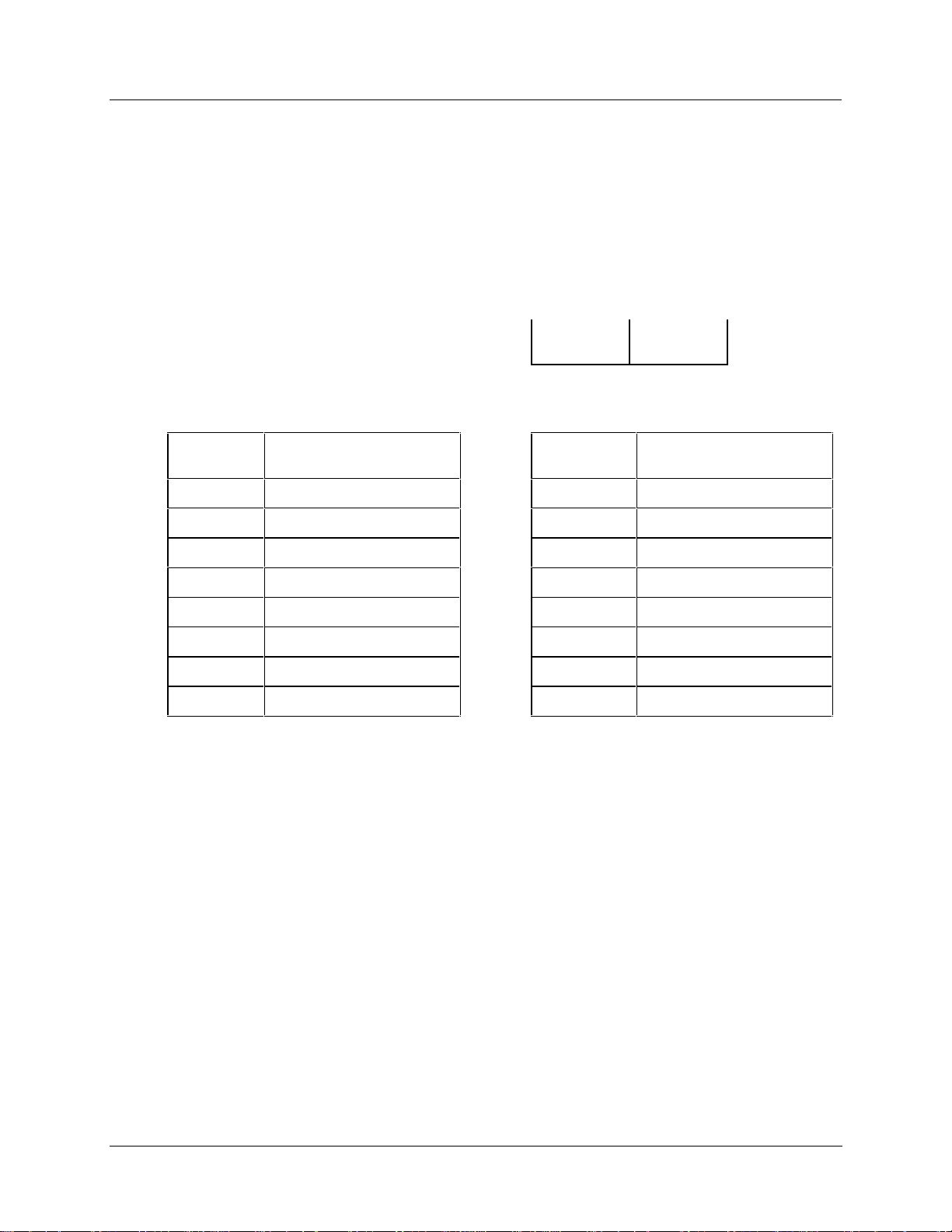
Controller model number
The controller model number speci fied on your purchase order indicates the I/O module types and the
assigned slot location of each I/O module present in the controller.
modules are defined below.
Example of controller model number
Mounting and Wiring
Plug-in Module Locations
The number fields that identify I/O
Controller Model Number
I/O module types and controller
locations for . . . Slots 1 to 8 Slots 9 to 16
8001 - 000 - 0E - 01122300 - 56800000
So the number 01122300 - 56800000 indicates that the controller is equipped with I/O module types in the
following slot locations:
Controller
Slot #
1 Blank (0) 9 DI AC Input (5)
2 Analog Input (1) 10 DO Relay Output (6)
3 Analog Input (1) 11 DO AC Output (8)
4 Analog Output (2) 12 Blank (0)
5 Analog Output (2) 13 Blank (0)
6 DI Logic Input (3) 14 Blank (0)
7 Blank (0) 15 Blank (0)
8 Blank (0) 16 Blank (0)
I/O Module Type
(Module ID)
Controller
Slot #
I/O Module Type
(Module ID)
NOTE: The numbers (in parenthesis) that identify the I/O module types are defined in Table 6.
Release F UMC800 Controller Installation and User Guide 21
4/01
Page 30
Mounting and Wiring
Plug-in Module Locations
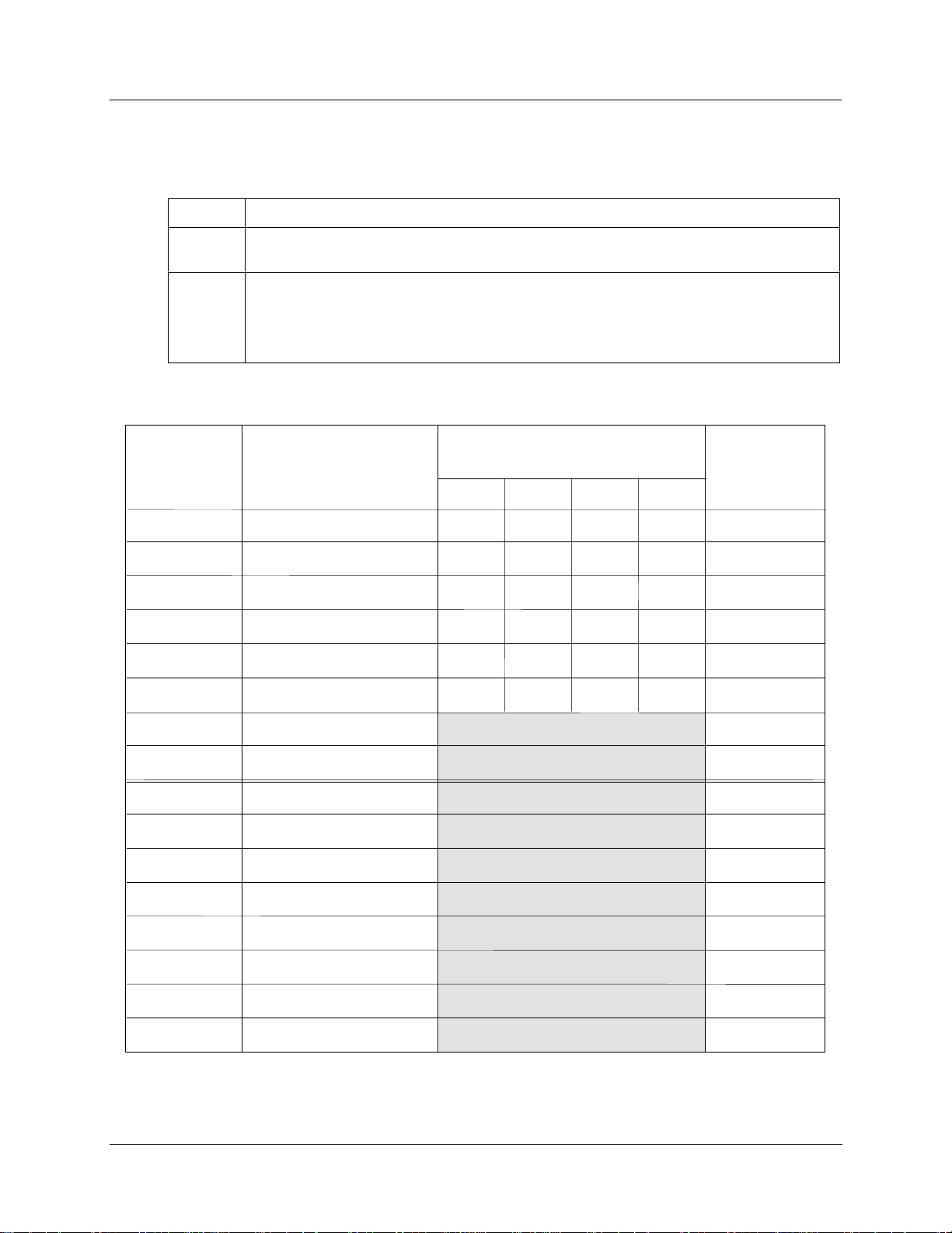
Verify I/O module locations
The table below outlines the steps for identifying and recording the I/O module types in the controller.
Step Action
1
2
Controller
Slot No.
1
2
3
4
5
Verify that the module types installed in the controller card slots are correct according to the
controller model number. Refer to Table 6 to identify the module types.
Use to record the location, module type and signal type/range for each I/O module installed
in the controller.
NOTE Module types should be installed in accordance with the limitations described in
Table 7.
Table 8 I/O module identification record
Signal Type/Range
I/O Module Type
(AI, AO, DI, DO, or PI/FI)
(mV, V, mA, T/C, RTD, Ohms, pH)*
Al Ch 1 Al Ch 2 Al Ch 3 Al Ch 4
Terminal Block
Color
6
7
8
9
10
11
12
13
14
15
16
* An Analog Input (AI) Module can be configured to accept multiple input types.
22 UMC800 Controller Installati on and User Guide Release F
4/01
Page 31

Signal Wiring
I/O module wiring
Terminal blocks are installed to the front of the I/O modules for connecting field device wiring as shown in
Figure 11. Terminal blocks are color coded and numbered to identify the I/O module type. (See Table 6.)
The terminal blocks are removable so that I/O modules can be replaced without disconnecting the field
wiring from the terminal blocks. Wire gauge sizes 16 to 22 AWG can be used to connect to the terminal
blocks. The field wiring exits through rubber grommets at the top or bottom of controller enclosure. The
rubber grommets are removed by sliding the grommet forward with the terminal block and the attached
field wiring.
I/O Module
Identification
12
11
10
9
8
7
6
5
4
Mounting and Wiring
Signal Wiring
Locks
2
Field Wiring
Terminals
3
2
1
Locks
Figure 11 I/O module terminal block (all except 16 point DI)
Release F UMC800 Controller Installation and User Guide 23
4/01
Page 32

Mounting and Wiring
Signal Wiring
Analog input / analog output field wiring
Shielded twisted pairs are recommended (and required for CE approval) for analog input (AI) and analog
output (AO) module field wiring. If a cabinet shield termination point is not available, the optional shield
termination bracket may be used, (specify part number 51309814-501). The shield termination point is a
bracket attached at the top and/or bottom on the front of the controller enclosure. The wiring shields are
attached using the screws of the shield termination. Figure 12 shows the field wiring termination strip
attached to the bottom front of the enclosure.
Figure 12 Field wiring shield termination
24 UMC800 Controller Installati on and User Guide Release F
4/01
Page 33

Analog inputs (module ID 1)
A universal Analog Input module accepts a variety of input signals from field devices as summarized in
Table 9. Figure 13 illustrates the terminal block connection s for the various inputs. See Specifications
section for more details on all I/O module specifications. One AI module can be configured to accept
multiple input types.
Table 9 Universal analog input module specifications
Specification Description
Input Types mV, V, mA, T/C, RTD, and Ohms
Number of Inputs 4 per module, up to 16 modules per controller (64 inputs)
Mounting and Wiring
Signal Wiring
RTD
RTD
RTD
RTD
Signal Source
Input Impedance
12
+
11
-
10
1
+
9
-
8
7
+
6
-
5
4
3
+
2
-
1
Thermocouple with cold junction compensation, for operation between 32 °F to
176 °F (0 °C to 80 °C)
Line resistance up to 1000 ohms, T/C, mV, mA, V
RTD Pt 100 3-wire connections, 40 ohms balanced max.
10 Megohms for T/C, mV inputs,
> 1 Megohms for volt inputs
Field Wiring
Channel 4
Thermocouple Input
+
T/C, mV, V
-
Current Input mA
4 to 20
mA
*
Source
+
-
Channel 3
Ground T er minal
* A 250 ohm res istor is required f or
the input range.
RTD Input (3 wires)
+
-
RTD
Ground Terminal
Channel 2
Channel 1
Ground Terminal
mV, V Inputs
mV or V
Source
Ground Terminal
+
-
Figure 13 AI module terminal block connections
Release F UMC800 Controller Installation and User Guide 25
4/01
Page 34

Mounting and Wiring
Signal Wiring
Field wiring for one pH sensor input (module ID C)
Figure 14 indicates the recommended wiring for one pH sensor input. Note that two analog input channels
are required, one for the pH sensor and one for temperature. Similar wiring may be used for additional
sensors. A UMC800 controller can accommodate 2 power modules for a total of up to 8 pH inputs.
UMC800 Controll er
Mod 1
Mod 4
pH 1 Sensor
Temp
pH 1 Sensor
mV
-
+
Analog Input
Module
Red/Black
Red
White
Orange
Black
COM
White/Black
(Unused)
Green
Blue
12
1
+
-
+
-
1
Jumper
12
C
-
C
+
-
C
+
-
C
+
1
UMC800 Shield Connector Kit
Part No. 51309814-501
Figure 14 Recommended wiring for one pH sensor input
Power Su pply Module
26 UMC800 Controller Installati on and User Guide Release F
4/01
Page 35

Analog outputs (module ID 2)
The Analog Output (AO) module provides four outputs at 0 mA to 20 mA (configurable for 4 mA to
20 mA or any span between 0 mA to 20 mA). When not used for an analog output, an output channel may
be used to power a transmitter with 24 Vdc power. The controller will support up to 4 AO modules, for a
total of 16 outputs. Figure 15 shows the terminal connections for the AO module. See Specifications
section for details on all I/O module specifications.
Mounting and Wiring
Signal Wiring
12
11
10
9
8
7
Channel 4
2
Field Wiring
Load
Channel 3
Ground Terminal
4 to 20 mA Output
+
-
4 to 20 ma
Generator
Gnd
6
5
4
3
2
Channel 2
Channel 1
Fiel d Wiring
24 V
+
DC
Power
-
1
Gnd
ATTENTION
Channels not used as analog outputs can be used to supply a transmitter with 24 Vdc power.
Figure 15 AO module terminal block connections
Release F UMC800 Controller Installation and User Guide 27
4/01
Page 36

Mounting and Wiring
Signal Wiring
Digital inputs
Three types of Digital Input (DI) modules accept four types of input signals.
1. Logic Input (Module ID 3 and B)
2. DC Input (Module ID 4)
3. AC Input (Module ID 5)
4. Pulse/Frequency Input (Module ID D)
Each type is described on the following pages. Figure 16 shows the terminal block connections for all DI
modules. See Specifications section for details on all I/O module speci fications.
ATTENTION
16 Point Digital Input module (ID B) has 32 terminals. If you are using 2 wires per DI, use 22
gage wires so all 32 wires can fit through the rubber grommet in the controller case. See
Figure 16.
28 UMC800 Controller Installati on and User Guide Release F
4/01
Page 37

Module B
Identifiable by
32 screws
2
+
4
6
8
10
12
14
16
18
20
22
24
26
28
30
32
Each odd-numbered
terminal is internally
grounded.
Gnd
DI 16
DI 15
DI 14
DI 13
DI 12
DI 11
DI 10
DI 9
DI 8
DI 7
DI 6
DI 5
DI 4
DI 3
DI 2
DI 1
Module ID
#3, 4, or 5
12
11
10
Mounting and Wiring
Signal Wiring
DI 6
DI 5
9
8
7
6
5
4
3
2
1
DI 4
DI 3
DI 2
DI 1
Module ID B (16 DI)
Logic Input (Conta ct Closure)
For 2 wires per DI, must use 22-gage wire to fit 32
wires through rubber grommet on case.
R
Field Wiring
Dry SW
Module ID B (16 DI)
Logic Input (Contact Closure)
For 1 common wire for all DIs, use 16-22 gage wire.
Field Wiring
Dry SW
Gnd
+ VCC
R
Gnd
+ VCC
• One wire per DI. Each wire goes to
Marshalling field connector (user provided).
• One common wire from Marshalling field
connector to any ground connector on the
16 pt. DI terminal.
Marshalling field
connector
Figure 16 DI module terminal block connections
Logic
Logic
Module ID #3
Logic Input (Contact Closure)
Field Wiring
Module ID #4
DC Input (24 Vdc )
Field Wiring
+
24V
-
Module ID #5
AC Input (120/240 Vdc)
Field Wiring
Dry SW
L1
L2
R
Gnd
+ VCC
+ VCC
+
R
-
+ VCC
R
Release F UMC800 Controller Installation and User Guide 29
4/01
Page 38

Mounting and Wiring
Signal Wiring
Digital outputs
There are four types of Digital Output (DO) modules that provide three types of Off/On control.
1. Relay (alarm) output (Module ID 6) 46190308-503
2. DC output (Module ID 7) 46190341-501
3. AC output (Module ID 8) 46190344-501
4. AC high output (Module ID A) 46190344-502
Figure 17 shows the terminal block connections for the DC output and AC output DO modules. See
Specifications section for details on all I/O module speci fication s.
Module ID #6
Relay(Alarm) Output
Module ID
#6, 7, 8,
or A
12
11
10
9
8
7
6
5
4
3
2
1
Modul e ID A
AC Output (120/240Vdc)
Wiring same as module 8.
Maximum Load Cur rent:
Outputs
DO 1 – 4 @ .5A
DO 5 and 6 @ 2A
DO 6
DO 5
DO 4
DO 3
DO 2
DO 1
Field Wiring
L1
L2
Load
Module ID #7
DC IOutput (24 Vdc)
Field Wiring
+
24V
-
Load
Module ID #8
AC Output (120/240 Vdc)
Field Wiring
L1
L2
Load
Fuse
Fuse
R
VCC
Figure 17 DO module terminal block connections
30 UMC800 Controller Installati on and User Guide Release F
4/01
Page 39

Mounting and Wiring
Signal Wiring
The Digital Output module with relay outputs (Module ID 6 ) contain jumpers to set the de-energized state
of the relay contacts. The relays are factory set to normally open (NO) for each output on the relay alarm
module, as shown in Figure 18.
To change the state of the contacts: Use a pair of needle-nose pliers and move the jumper from the location
NO (normally closed) to the location NC (normally closed).
Digital Output
Module
Normally Open
Contacts
NO
NC
NC6
S6
NO6
NC5
S5
NO5
NC4
S4
NO4
NC3
S3
NO3
NC2
S2
NO2
NC1
S1
NO1
Normally Closed
Contacts
12
11
10
!
9
8
7
6
5
4
NO NC
3
2
1
Figure 18 DO module relay contact setting
Release F UMC800 Controller Installation and User Guide 31
4/01
Page 40

Mounting and Wiring
Signal Wiring
Pulse input/frequency input module with digital outputs
Figure 19 shows the terminal block connections for Pulse/Frequency Input Module. See Specifications
section for details on all I/O module specifications.
ATTENTION
16 Point Digital Input module (ID D) has 32 terminals. If you are using 2 wires per DI, use 22
gage wires so all 32 wires can fit through the rubber grommet in the controller case. See
Figure 19.
Module ID - D
Identifiable by
32 screws
2
+
4
6
8
10
12
14
16
18
20
22
24
26
28
30
32
Each odd-numbered
terminal is internally
grounded.
Gnd
Input 1 +
Input 1 Input 2 +
Input 2 DO1 +
DO1 DO2 +
DO2 DO3 +
DO3 -
DO4 +
DO4 Input 3 +
Input 3 Input 4 +
Input 4 -
Figure 19 PI/FI module terminal block connections
32 UMC800 Controller Installati on and User Guide Release F
4/01
Page 41

Pulse input/frequency input jumpers
The Pulse/Frequency Input Module with Digital Outputs (M odule ID D) contain jumpers to set the deenergized Input Filter Cutoff Frequency. All four inputs are factory set to 500 KHz as shown in Figure 23.
To change, use needle nose pliers and move the jumper(s) to the desired position. See the figure below for
the default positions and jumper settings for 100 KHz and 5 KHz.
4
6
1
9
0
3
6
0
-
5
0
1
Pulse/Frequency Input Board
OFF
JX1 -
JX2 -
ON
Mounting and Wiring
Signal Wiring
1
500KHz
2
1
100KHz
2
1
5KHz
2
JA1
JA2
JB1
JB2
Figure 20 PI/FI module input filter cutoff frequency setting
Pulse/frequency card wiring
The pulse frequency card input is designed to accept a contact closure type transmitter. The typical wiring
circuit is shown below.
+
-
Pulse Transmitter
MOSFET, Open Collector, or
Contact Closure drive.
V Supply (DC)
R
L
V Return (DC)
JC2
JC1
JD2
JD1
+
RT=1k
+
Note: All puls e
-
frequency inputs
share a return
connection that is
common to all pulse /
frequency inputs on a
card.
Pulse / Frequency Input Card
Input Connections
Figure 21 Pulse/frequency input connections
Release F UMC800 Controller Installation and User Guide 33
4/01
Page 42

Mounting and Wiring
Signal Wiring
V supply
Choose a supply that is compatible with the environmental require ments o f your application. The supply
voltage must be within the requirement of both the transmitter and the pulse input card. Typically a low
cost 12 Vdc unregulated supply can be used in most applications provided in meets applicable regulatory
requirements. 1k ohm termination resistors (R
the internal resistor must meet pulse frequency card requirements. The circuit in Figure 21 provides for a
1 k ohm load resistor and a 12 V supply. The actual pulse voltage seen across the pulse \ frequency input is
divided by R
volts. For a 1 k ohm load the minimum V supply will be 3 V (R
V return
The pulse / frequency cards pulse inputs are optically isolated from other circuitry but share a common
isolated supply common. When multiple inputs are used the supply voltage returns will be connected to a
common reference internal to the pulse frequency card. The pulse / frequency cards digital outputs are
optically isolated from all inputs and each other.
R
L
The maximum sink current specified by the pulse transmitter specifies the minimum load resistance.
Typically R
) are built into the pulse frequency card. The voltage across
T
/(RL+RT) V
T
is within the range of 100 to 100k ohms. A 1 k ohm resistor is typically recommended.
L
= 6 V. The VIH minimum pulse threshold voltage for the pulse input card is 3
Supply
)/ RT = 6V.
L+RT
The transmitter often provides a selection for the pulse duration or width. The pulse input card internal R/C
filtering will attenuate short pulse widths. Below is a table for filter and pulse width settings for several
pulse freque nc y ran ge s.
Max Pulse Frequency Typical Filter Jumper Setting Pulse Width Range
100kHz 500 K Hz 2 uSec to 9 uSec
10kHz 100 K Hz 9 uSec to 90 uSec
1kHz 5 K Hz 180 uSec to 900uSec
100Hz 5 K Hz 180 uSec to 9mSec
(Vsupply = 12 Vdc, RL = 1 K ohm)
The minimum pulse frequency is 10 Hz regardless of the filter jumper settings.
The pulse frequency card input wiring requirements must be compatible with both the pulse frequency card
and the transmitter manufactures specifications. A typical transmitter will specify the maximum supply
voltage and the maximu m sink current.
34 UMC800 Controller Installati on and User Guide Release F
4/01
Page 43

Pulse frequency card outputs
The pulse frequency card outputs are open collector drivers designed to drive a maximum of 100 mA. All
Pulse Frequency card digital outputs are optically isolated from each other. The maximum supply voltage
must not exceed 27 Volts dc.
Mounting and Wiring
Signal Wiring
V Supply (DC) 27 V Max
IL (100mA Max)
V Return (DC)
+
+
Pulse / Frequency Input Card
DO connections
Figure 22 Pulse/frequency card digital output connections
Release F UMC800 Controller Installation and User Guide 35
4/01
Page 44

Mounting and Wiring
Wiring Communication Links
Wiring Communication Links
Serial communications ports
The controller communicates through a number of serial ports. The CPU module contains two serial ports.
One is an RS 232 connection to a PC and another is dedicated for connection to the operator interface. The
CPU with optional communications features two additional RS 485 serial ports.
The serial port connectors on the CPU module are shown in Figure 23. Table 10 summarizes the
communication link connections to the controller and other reference data for wiring details.
OFFLINE
PROGRAM
RUN
Pin 1
Pin 9
POWER
LoBAT
FORCE
RUN
Repl ac e ba t ter y with T a di ra n T L5 10 1/ S
on ly. Us e o f ano t her ba tt er y ma y
pre se nt a ri s k of fi re or e x pl os i on .
BAT
CPU
See users guide for instructions.
CONFIGURATION
CONFIGURATION
Power
Supply
DISPLAY
Ope rat or Inter fac e
Connector for optional
RS 485 Serial Interface
COMM B COMM A
slave communications.
Connector for optional
RS 485 Serial Interface
master communications
Connector for PC
Interface cable
(Null Modem)
DISPLAY
Connector for
cable
COMM A
COMM B
Figure 23 Communication port connectors
36 UMC800 Controller Installati on and User Guide Release F
4/01
Page 45

Mounting and Wiring
Wiring Communication Links
Table 10 Summary of communication link connections to controller
Communication
Link to . . .
PC or laptop (via
Null Modem cable
or via modem)
Operator interface RS 422
Modbus Link
(optional
communications
board)
Modbus Link
(optional
communications
board)
Link Type
RS 232
RS 485
(Half
Duplex)
RS 485
(Half
Duplex)
From Controller
Port
CONFIGURATION
(9-pin “D”
connector)
DISPLAY
(15-pin “D”
connector)
COMM A
(4-wire + shield or
2-wire shielded
with external
jumpers
COMM B
(4-wire + shield or
2-wire shielded
with external
jumpers
Connect
Cable
Up to 50 ft
cable lengths
(Supplied by
user)
10 ft or 50 ft
cable lengths
available.
Up to 2000 ft
cable lengths
(Supplied by
user)
Up to 2000 ft
cable lengths
(Supplied by
user)
To Port Reference Data
Serial port of PC. Null Modem
cable, 9-pin
Male/Female
See Table 11.
Modem: See
Remote Access
(page 44)
Terminal connector
of operator
interface.
Modbus
communications
and PC host.
Modbus
communications
and slave devices.-
See Table 12.
See Figure 26.
See Figure 26.
CONFIGURATION connector
The Configuration connector accommodates a 9-pin D-type Null Modem cable connection to the serial
RS-232 input of a PC or laptop computer. Table 11 describes the pinouts for the connector. See Figure 23
for the pin numbering. If you need to construct the cable, Table 12 shows the make up of the cable.
Table 11 Configuration connector pinouts
Configuration Connector Pinouts
(For Null Modem Cable)
Signal Name Terminal No.
DCD 1
RXD 2
TXD 3
DTR 4
GND 5
DSR 6
RTS 7
CTS 8
RI 9
Release F UMC800 Controller Installation and User Guide 37
4/01
Page 46

Mounting and Wiring
Wiring Communication Links
CONFIGURATION cable
Table 12 Null modem cable construction
PC Connector
9-Pin “D” Female
Pin Pin
2
3
5
4
6
7
8
UMC800
9-Pin “D” Male
2
3
5
4
6
7
8
Order part number -
51404755-501
38 UMC800 Controller Installati on and User Guide Release F
4/01
Page 47

Installing ferrite clamp for CE compliance
This procedure ensures that unwanted radio frequency noise is filtered. It is r equired for CE compliance.
Parts needed
Part # Quantity Description
047260 1 Ferrite cable cla mp s
089037 2 Nylon cable ties
Installing ferrite clamp
Step Action
Mounting and Wiring
Wiring Communication Links
1
2
3
4
5
Disconnect all power to the instrument.
See Figure 24. Attach the ferrite clamp around all the wires as close to the Configuration port
terminals as possible (within ½” of the terminals). For maximum shielding you must minimize
the amount of unshielded exposed wire. The ferrite clamp should overlap or abut the cable
shield enclosing the wires.
Snap the ferrite clamp closed, making sure to not pinch the wires.
To prevent the ferrite clamp from sliding, attach cable ties around the wires snugly against each
end of the ferrite clamp.
Trim the cable tie but leave a “tail” of approximately 1”.
C
a
b
l
e
Terminals
Attach ties snugly
against each side of
the clamp.
Figure 24 Ferrite clamp installation
Release F UMC800 Controller Installation and User Guide 39
4/01
Page 48

Mounting and Wiring
Wiring Communication Links
DISPLAY connector (to operator interface)
The controller is connected to the operator interface through a 15-pin D-Type connector cable. One cable
end is connected to the DISPLAY connector of the controller. The other end connects to a 10-pin in-line
connector at the rear of the operator interface case. This cable end must be made, since some installations
may require the cable to be run through conduit. Table 13 shows the pinouts for the operator interface end
of the cable. Figure 25 shows the connector location at the rear of the operator interface.
Table 13 Operator interface connector pinouts
Operator Interface Connector Wiring
Signal Name Wire Color Terminal No.
Receive –
Receive +
Receive Shield
Transmit Shield
Transmit –
Transmit +
Signal Ground
Signal Ground
Outer Shield
- - - - - - - +24 Vdc *
+24 Vdc *
Black
White
Shield
Shield
Black
Red
Black
Green
Shield
- - - - Black
Blue
1
2
3
4
5
6
7
8
9
10
*
CAUTION: For 24 Vdc, make sure that the wiring is on terminals #9 and
#10. The CPU board may be damaged if the wiring is accidentally connected
to terminals #1 and #2.
40 UMC800 Controller Installati on and User Guide Release F
4/01
Page 49

Connector location at the rear of the operator interface
551 Operator Interface
Rear
Connector Terminal Wiring
Signal Wire Terminal
Name Color Number
RX- Black 1
RX+ White 2
RX Shd. Shield ----- 3
TX Shd. Shield --TX- Black 4
TX+ Red 5
Sig. Gnd Black ------ 6
Sig. Gnd Green --Outer Shd. Shield 7
Not Used Not Used 8
+24 VDC Black 9
+24VDC Blue 10
552 Operator Interface
Rear
Connector Terminal Wiring
Signal
Name
+24VDC
+24VDC
Not Used
Outer Shield
24V Shield
Sig. Gnd. Shield
Sig. Gnd
Sig. Gnd
TX+
TXTX Shd.
RX Shd.
RX+
RX-
Wire
Color
Blue
Black
Not Used
Shield
Shield
Shield
Green
Black
Red
Black
Shield
Shield
White
Black
Terminal
Number
10
9
8
7
6
5
4
3
2
1
Mounting and Wiring
Wiring Communication Links
Connector
for Cable
from Controller
Connector
for Cable
from Controller
1041 Operator Interface
Rear
Connector Terminal Wi ring
Signal Wire Terminal
Name Color Number
RX- Black 1
RX+ White 2
RX Shd. Shield ----- 3
TX Shd. Shield --TX- Black 4
TX+ Red 5
Sig. Gnd Black ------ 6
Sig . Gnd Green --Outer Shd. Shield 7
Not Used Not Used 8
+24 VDC Black 9
+24VDC Blue 10
Connector
for Cable
Connector
for Keyboard
from Controller
Figure 25 Terminal connections
Release F UMC800 Controller Installation and User Guide 41
4/01
Page 50

Mounting and Wiring
Wiring Communication Links
COMM A and B connectors (optional)
The CPU module equipped with the optional communicatio n board provides two additional RS 485
communications ports with Modbus RTU protocol support. COMM A port allows the UMC800 controller
to network with up to 31 other slave UMC800 controllers and devices on a Modbus link. COMM B port
allows the UMC800 controller to be a master to up to 16 slave UMC800 controllers and devices on a
Modbus link.
Figure 26 shows the COMM A and B connector wiring when using either a shielded twisted pair or 4-wire
shielded cable.
NOTE: When using the RS 485 communications, it is recommended that an RS 485 to RS 232 converter
(such as Black Box model IC901A) be used to interface with the host PC. Also, be certain that the Half
Duplex Turnaround Delay parameter for the converter set to 1 millisecond or less.
2-Wire
Shielded
Shield
Receive
Transmit
+
_
+
_
COMM A
Shield
Receive
Transmit
ATTENTION
Make sure you connect the correct polarity. If the TX+ and TX– connections are reversed from
the correct connections, an error message will be generated when attempting to do any
communications and the program then self-terminates.
+
_
+
_
Figure 26 COMM A and B port wiring (2-wire and 4-wire)
COMM B
Shield
Receive
Transmit
Shield
Receive
Transmit
4-Wire
Shielded
+
_
+
_
+
_
+
_
COMM A
COMM B
42 UMC800 Controller Installati on and User Guide Release F
4/01
Page 51

RS 485 serial communications
When connecting the controller to a RS 485 communication link (see Figure 27), you must use termination
resistors at each end of the link. The following cables with the listed resistor values can be used for
connecting the controller.
RS 485 Cables: Belden #9271 (or equivalent) with 120 ohm termination resistors (2,000 ft. maximum)
Belden #9182 (or equivalent) with 150 ohm termination resistors (4,000 ft. maximum)
Computer
Mounting and Wiring
Wiring Communication Links
OFFLINE
RUN
PROGRAM
Host
CONFIGURATION
POWER
LoBAT
FORCE
RUN
RS232/RS485
Converter*
*RS 485 communications
requires termination resistors
at each end.
Figure 27 RS 485 port wiring (2 wire)
Controller with Optional
Communications Board
To other UMC800 Controllers*
Repl ac e batt er y wit h Ta dira n TL5 10 1/ S
BAT
only. Use of another battery may
present a risk of fire or explosi on.
See users guide for instructions.
DISPLAY
COMM B COMM A
_
100 - 240 V ~
50 / 60 Hz
100 VA MAX.
F 3,15 AT
250V
L1
L2 / N
Release F UMC800 Controller Installation and User Guide 43
4/01
Page 52

Mounting and Wiring
Remote Access
Remote Access
Overview
Remote controller access via dial-up modem is available via the communication setup. An external modem
is required at the controller and is connected to the standard RS232 configuration port (marked
“CONFIGURATION”). All functions of the Control Builder and User Utility pr ograms can be performed
over this link. Remote access functions include on-line monitoring, configuration upload and download,
and firmware upgrade.
Modem requirements
Most commercially available modems can be used with the UMC800 controller. The modem must have the
following capabilities:
• RS232 interface
• Auto answer
• Can operate at 9600 baud, 8 data bits, 1 stop bit, and no parity
• Hardware handshaking ca n be disabled
• Software handshaking can be disabled
• Data Terminal Ready (DTR) input can be disabled
• Result codes can be suppressed
• Echo can be disabled
• Must be equipped with non-volatile memory (NVRAM) so that settings that are configured using
command strings can be retained during a power-outage
• Must be able to load the NVRAM settings automatically on power-up
Cable requirements
You will need an interface cable to connect the modem to the DB-9 female connector (marked
“CONFIGURATION”) on the controller. If your modem has a 25-pin connector, be sure to use a DB-25 to
DB-9 modem cable.
TIP
The Null Modem cable used to directly connect a PC running Control Builder Software to the
controller may typically not be used to connect the PC to the modem or to connect the modem
to the controller.
If your modem requires command string configuration, you will need an interface cable to connect the
modem to your PC. Refer to your modem and computer documentation to determine this cable’s
requirements.
44 UMC800 Controller Installati on and User Guide Release F
4/01
Page 53

Modem configuration
Before connecting a modem to the controller’s RS232 port (marked “CONFIGURATION”), the modem
must be configured with the following settings:
• Baud Rate = 9600
• Parity = None
• 1 stop bit
• 8 data bits
• No handshaking
• Ignore DT R
• Suppress result codes
• Suppress echo
• Auto answer
• Disable command recognition (only necessary if the modem has this capability)
Mounting and Wiring
Remote Access
Some of these settings may be settable via switches. Others may require command strings to be written to
the modem using a PC terminal program such as Hyperterminal. You will need to refer to your modem’s
documentation to make this determination. Those settin gs that are configured using command strings must
be saved to the modem’s non-volatile RAM (NVRAM), and the NVRAM must be configured as the profile
that gets loaded when the modem is powered up.
Most modems are equipped with auto-recognition to set the baud rate, parity, stop bits, and data bits. If
your modem has no means of setting these using switches, then most likely it is equipped with autorecognition. To configure the port settings of a modem with auto recognition, do the following:
Step Action
1
Connect the modem to a PC.
2
Power up the modem.
3
Start up a PC terminal program such as Hyperterminal.
4
Configure the port for 9600 baud, no parity, 1 stop bit, and 8 data bits.
5 Establish communications with the modem. A common way of doing this is simply entering the
AT E1 Q0 command and seeing if the modem responds with OK.
Once you establish communication to the modem, its port settings are configured.
6
Save the port settings to the profile that gets loaded on power-up.
Release F UMC800 Controller Installation and User Guide 45
4/01
Page 54

Mounting and Wiring
Remote Access
Modem configuration examples
Below are procedures for setting up the following commercially available modems:
• 3Com US Robotics 56K Data/Fax External Modem
• Zoom 56K Dualmode External Modem
• Best Data 56SX Data Fax External Modem
• SixNet VT-MODEM Industrial External Modem
3Com US Robotics 56K Data/Fax External Modem
Step Action
1
Ensure that the switches are set to the factory settings:
Switch Setting Position Function
1 OFF UP Normal DTR operations
2 OFF UP Verbal (word) results
3 ON DOWN Enable result codes
4 OFF UP Displays keyboard commands
5 ON DOWN Disables auto answer
6 OFF UP Modem sends CD signal when it connects with another
7 OFF UP Loads Y0-Y4 configuration from user-defined
8 ON DOWN Enables recognition (smart mode)
modem
nonvolatile memory (NVRAM)
2
Connect the modem to a PC. If your computer’s RS232 port has a 25-pin connector, use a
DB-25 male to DB-25 female RS232 cable. If your computer’s RS232 port has a 9-p in
connector, use a DB-25 male to DB-9 female modem cable.
3
Power-up the modem.
4
Run a serial communication port program such as Hyperterminal.
5
Within the communication program, select the port to which the modem is connected.
6
Configure the port to these settings:
baud rate = 9600
data bits = 8
parity = none
stop bits = 1
flow control = none
7
In the program’s terminal window, type in the letters “AT” followed by the enter key. The
modem should give an OK response.
8
Power down the modem and disconnect it from the PC.
46 UMC800 Controller Installati on and User Guide Release F
4/01
Page 55

Step Action
9
Set the modem switches to the following:
Switch Setting Position Function
1 ON DOWN Modem ignores DTR (Override)
2 OFF UP Verbal (word) results
3 OFF UP Suppresses result codes
4 ON DOWN Suppresses echo
5 OFF UP Modem answers on first ring
6 ON DOWN CD always ON (Override)
7 OFF UP Loads Y0-Y4 configuration from user-defined
nonvolatile memory (NVRAM)
8 OFF UP Disables command recognition (dumb mode)
Mounting and Wiring
Remote Access
10
11
12
13
14
15
Connect the modem to the RS232 port of the UMC800 using a DB-25 male to DB-9 male
RS232 cable. Null modem cable may not work.
Connect the modem to a telephone jack.
Power up the modem and the UMC800.
On a remote computer, run Control Builder software.
Setup Control Builder to dial the UMC800.
Verify that communications is established with the remote UMC800.
Release F UMC800 Controller Installation and User Guide 47
4/01
Page 56

Mounting and Wiring
Remote Access
Zoom 56K Dualmode External Modem
Step Action
1
Connect the modem to a PC. If your PC’s RS232 port has a 25-pin connector, use a DB-25
male to DB-25 female RS232 cable. If your PC’s RS232 port has a 9-pin connector, use a
DB-25 male to DB-9 female modem ca ble.
2
Connect power to the modem.
3
Power up the modem.
4
Run a serial communication port program such as Hyperterminal.
5
Within the communication program, select the port to which the modem is connected.
6
Configure the port to these settings:
baud rate = 9600
data bits = 8
parity = none
stop bits = 1
flow control = none
7
In the program’s terminal window, type in the letters “AT E1 Q0” followed by the enter key. The
modem should give an OK response.
8
9
10
11
12
13
14
15
16
Enter the following command string:
AT &Y0 &C0 &D0 &R1 &S0 &K0 S0=1
Modem should respond with OK.
Enter the following command string:
AT E0 Q1 &W0
Modem will not respond.
Power down the modem and disconnect it from the PC.
Connect the modem to the RS232 port of the UMC800 using a DB-25 male to DB-9 male
RS232 cable. Null modem cable may not work.
Connect the modem to a telephone jack.
Power up the modem and the UMC800.
On a remote computer, run Control Builder software.
Set up Control Builder to dial the UMC800.
Verify that communications is established with the remote UMC800.
48 UMC800 Controller Installati on and User Guide Release F
4/01
Page 57

Best Data 56SX Data Fax External Modem
Step Action
1
Connect the modem to a PC. If your PC’s RS232 port has a 2- pin connector, use a DB-9 male
to DB-25 female modem cable. If your PC’s RS232 port has a 9-pin connector, use a DB-9
male to DB-9 female RS232 cable.
2
Connect power to the modem.
3
Power-up the modem.
4
Run a serial communication port program such as Hyperterminal.
5
Within the communication program, select the port to which the modem is connected.
6
Configure the port to these settings:
baud rate = 9600
data bits = 8
parity = none
stop bits = 1
flow control = none
7
In the program’s terminal window, type in the letters “AT E1 Q0” followed by the enter key. The
modem should give an OK response.
Mounting and Wiring
Remote Access
8
9
10
11
12
13
14
15
16
Enter the following command string:
AT &C0 &D0 &K0 &R1 &S0 &Y0 S0=1
Modem should respond with OK.
Enter the following command string:
AT E0 Q1 &W0
Modem will not respond.
Power down the modem and disconnect it from the PC.
Connect the modem’s serial cable to the RS232 port of the UMC800 using a DB-9 male to
DB-9 male RS232 cable. Null modem cable may not work.
Connect the modem to a telephone jack.
Power up the modem and the UMC800.
On a remote computer, run Control Builder software.
Set up Control Builder to dial the UMC800.
Verify that communications is established with the remote UMC800.
Release F UMC800 Controller Installation and User Guide 49
4/01
Page 58

Mounting and Wiring
Remote Access
SixNet VT-MODEM Industrial External Modem
Step Action
1
Connect the modem to a PC. If your PC’s RS232 port has a 25 pin connector, use a DB-9
male to DB-25 female modem cable. If your PC’s RS232 port has a 9 pin connector, use a
DB-9 male to DB-9 female RS232 cable.
2
Connect power to the modem. You will need to supply an external power supply with a DC
voltage between 10 and 30 VDC.
3
Power-up the modem.
4
Run a serial communication port program such as Hyperterminal.
5
Within the communication program, select the port to which the modem is connected.
6
Configure the port to these settings:
baud rate = 9600
data bits = 8
parity = none
stop bits = 1
flow control = none
7
8
9
10
11
12
13
14
15
16
In the program’s terminal window, type in the letters “AT E1 Q0” followed by the enter key. The
modem should give an OK response.
Enter the following command string:
AT &Y0 &C0 &D0 &R1 &S0 &K0 S0=1
Modem should respond with OK.
Enter the following command string:
AT E0 Q1 &W0
Modem will not respond.
Power down the modem and disconnect it from the PC.
Connect the modem to the RS232 port of the UMC800 using a DB-9 male to DB-9 male
modem cable. Null modem cable may not work.
Connect the modem to a telephone jack.
Power-up the modem and the UMC800.
On a remote computer, run Control Builder software.
Setup Control Builder to dial the UMC800.
Verify that communications is established with the remote UMC800.
50 UMC800 Controller Installati on and User Guide Release F
4/01
Page 59

Power Supply Wiring
The power wiring is connected to the power terminals of the power supply in accordance with accepted
wiring practices and is summarized in Table 14 shows the terminal connections for the power wiring.
CAUTION
Mounting and Wiring
Power Supply Wiring
F 3,15 AT
250V
L1
L2 / N
Figure 28 Power supply terminal connections
Ground wiring
PROTECTIVE BONDING (grounding) of this controller and the enclosure in which it is installed shall be
in accordance with National Electrical Code (ANSI/NFPA 70) and local electrical codes.
Prepower checks
Before applying power to the controller file, verify that:
• The controller has been mounted in accordance with the instructions in this manual.
• The power wiring is correct and meets all local and national electrical codes.
Do not apply power to the controller at this time.
Table 14 Power supply wiring
Wire Designation Connect to Power
Terminal Designated
Hot L1 (+ DC)
Neutral L2 / N (– DC)
Ground
Release F UMC800 Controller Installation and User Guide 51
4/01
Page 60

Operation
Power Up / Power Down
Power Up / Power Down
Power-up
A sequence of checks are performed by the controller anytime power is applied to the controller. These
checks are a set of internal diagnostics that are completed in less than 10 seconds after power up and verify
the integrity of the controller hardware, the configuration database and firmware. Communication between
the operator interface and controller is established automatically after these checks are completed. All
outputs are OFF until addressed by the CPU.
Two start up routines are used for initializing the controller configuration.
A warm start is the default routine that is used to restart the controller operation. A warm start begins the
scan cycle of data points using all dynamic data retained from the previous legitimate scan.
A cold start (New start) initializes all control functio ns to their default initial state, (if default output
values are defined in the configuration). If defined, these values are used as the starting values for
controller operation.
Operation
Status indicators on the CPU module consist of four LEDs that indicate normal operation and diagnostic
fault conditions. See Status Indicators (page 59).
When power is applied to the controller, it will power up and initialize to the mode determined by the mode
switch setting on the CPU. See Mode control (page 53) for further information.
Power-down
The controller does not require the configuration to be reloaded when power is restored after a power loss
or power down. During a power interruption, the controller configuration is maintained in batter y-backed
RAM and a flash PROM on the CPU module. When the controller power is restored, and provided that the
battery power to the CPU RAM is not interrupted, the controller will perform a warm start. However, if
battery power to the RAM is interrupted, the controller configuration (whic h was last stored in the flash
PROM on the CPU), will be restored to the RAM when controller power is restored and then the controller
will perform a cold start.
CAUTION
Controller configuration is stored in RAM as well as the flash PROM on the CPU. However, if
you make changes to the configuration while the controller is in Run mode, the changes are
stored in RAM and not in the flash PROM. Therefore, if battery power is interrupted to RAM
during a power down condition, the configuration changes will be lost since controller
configuration will be restored from flash PROM.
Also, the real time clock will need to be set if battery power is interrupted during a power down
condition.
52 UMC800 Controller Installati on and User Guide Release F
4/01
Page 61

Operational Modes and Controls
There are three operational modes defined in the UMC800 to provide safe operating environments for users
to implement changes and perform tasks on the controller and operator interface.
1. PROGRAM Mode
2. RUN Mode
3. OFFLINE Mode
Safeguards are built into the operating system to prevent conditions that could otherwise cause process
upsets or equipment malfunctions.
PROGRAM mode
The Program mode is used to download controller configuration files that contain signal flow and
processing details of the control configuration. When the contro ller is set to Program mode, all input signal
processing is stopped and all output signals and logic status are held at their last values. Also, DO function
blocks that are configured as Time Proportional Outputs (TPOs) are turned off.
When the controller is switched from Program mode to Offline or Run, the controller performs a cold start
and controller configuration is b acked up to flash PROM.
Operation
Operational Modes and Controls
RUN mode
The Run mode is used for norma l operation of the control system. All I/O processing is active and operator
actions are supported.
OFFLINE mode
The OFFLINE mode is used to download controller files such as setpoint profiles, recipes and data storage
files. Calibration of I/O modules and setting the real-time clock ca n also be performed with the controller in
the OFFLINE mode. When the controller is set to OFFLINE mode, all input signal processing is stopped
and all output signals and logic status are held at their last values. Also, DO function blocks that are
configured as Time Proportional Outputs (TPOs) are turned off. When the controller is switched from
OFFLINE mode to RUN, the controller performs a warm start.
Mode control
The controller mode can be set and changed in a number of ways (with certain restrictions) by:
1. A manual switch located on the CPU module of the controller. OFFLINE – RUN – PROGRAM).
See Table 15.
The switch on the controller CPU is a “pull and set” locking toggle that allows you to manually
switch the controller to one of the three operational modes. When the switch is set to either RUN or
OFFLINE, the mode can be overridden and changed by a command through the Configuration port.
However, when the manual switch is set to PROGRAM, the mode cannot be overridden.
CAUTION
The manual switch on the controller CPU module always determines the mode (PROGRAM,
RUN or OFFLINE) by reading the position of the switch when power is applied to the
controller. The controller will power up and initialize to the state of the manual switch position,
regardless of the controller mode before the controller was powered down.
Release F UMC800 Controller Installation and User Guide 53
4/01
Page 62

Operation
Operational Modes and Controls
2. From the Operator Interface.
Mode changes can be made from SET MODE display or the Calibrate AI and AO displays of the
operator interface with certain restrictions. When the manual switch is set to PROGRAM, you cannot
change the mode to RUN or OFFLINE using the operator interface. The operator interface is active in all
modes.
3. Through the CONFIGURATION Port.
A PC, running the Control Builder software, connected to the Con fi guration port can initiate mode
changes to the controller. The control builder places the controller in PROGRAM mode when
downloading files to the controller.
Restrictions on mode control
Mode control of the controller has the following restrictions:
• When the controller manual switch is set to RUN, the mode can be changed to OFFLINE or PROGRAM
by commands from the configuration port or the operator interface.
• When the manual switch is set to OFFLINE, the mode can be changed to PROGRAM by commands
from the configuration port or the operator interface. The mode cannot be changed to RUN from the
configuration port or the operator interface.
• When the manual switch is set to PROGRAM, no mode changes can be made by commands from the
configuration port or the operator interface.
Table 15 summarizes the mode change interactions and restrictions.
Controller
Mode
Switch
CPU Module
OFFLINE
RUN
PROGRAM
POWER
LoBAT
FORCE
RUN
Replace battery with Tadiran TL5101/S
only. Use of another battery may
present a risk of fire or explosion.
See users guide for inst ruc tions.
BAT
CONFIG U RA TION
_
DISPLAY
100 - 240 V ~
50 / 60 Hz
100 VA MAX.
Figure 29 Controller mode switch location
54 UMC800 Controller Installati on and User Guide Release F
4/01
Page 63

Operational Modes and Controls
Table 15 Controller mode switch summary
Operation
Controller Mode Manual
Switch setting
RUN
OFFLINE
PROGRAM
through the Configuration Port or Operator Interface
Unrestricted mode changes.
The mode selected via the Configuration port or operator interface
overrides the controller manual mode switch position.
Can override OFFLINE mode to set controller to PROGRAM mode.
No mode changes can be made.
Setting mode switch to PROGRAM and then to RUN
Setting the controller mode switch to PROGRAM and then to RUN forces t he controller to perform a cold
start and other actions depending upon the condition of the database RAM.
changed from PROGRAM to RUN, the controller verifies that a valid database confi guration is present in
RAM before starting control loops.
So that,
If . . . (Condition of RAM) Then . . . (Controller Action)
A valid database configuration is present in RAM, Configuration is written to flash PROM. (User-
Database configuration in RAM is found to be bad,
but the configuration in flash PROM is good,
Mode Control
When the mode switch is
defined variables are initialized to zero.)
RAM is restored from the flash PROM that
contains the configuration values from the last
cold start.
[See CAUTION in Power Up / Power Down
(page 52).]
If the database configuration is found to be bad in
both RAM and flash PROM,
Controller is set to a null default configuration.
A system diagnostic INVALID CONFIG. is
generated.
In all cases the controller performs a cold start when the controller mode is set to PROGRAM and then to
RUN regardless of what method is used to change the mode.
Whether the mode was set through the
Configuration port or the operator interface, this action causes the PROGRAM mode to be cleared.
Additionally, setting the mode switch to PROGRAM and then RUN allows you to c hange the controller
mode if communications were disconnected to the Configuration port or operator interface while the
controller was still in PROGRAM mode.
Release F UMC800 Controller Installation and User Guide 55
4/01
Page 64

Operation
File Downloading
File Downloading
Downloading configuration files, recipes and other files to the controller can be accomplished two ways:
1. Download from a PC or other device connected the Configuration port (serial port) of the controller.
2. Using the operator interface to download files stored on a floppy disk.
These files include recipes,
setpoint profiles and data storage files.
There are mode restrictions on the downloading of certain configuration files. For example, the controller
must be in the Program mode before downloading a controller configuration file.
(Program mode is set
using either the controller manual mode switch, the SET MODE display of the operator interface or issuing
a command to the controller through the Configuration port.)
Downloading recipe information and read/write of specific parameters is permitted when the controller is in
the Program mode, as well as the Run or Offline modes. See Table 16 for a file downloading summary.
Table 16 Controller downloading summary
Downloading . . . Permitted When Controller is in . . .
PROGRAM Mode RUN Mode OFFLINE Mode
Controller Configuration Files
Setpoint Profiles / Setpoint
Schedule
Recipe Files
Data Storage Configuration Files
Data Storage Non-volatile
parameters
Yes No No
Yes Yes Yes
Yes Yes Yes
Yes No Yes
Yes Yes Yes
Also, there are mode restrictions for these procedures . . .
Calibration
Real-time Clock Change
56 UMC800 Controller Installati on and User Guide Release F
Yes No Yes
Yes Yes Yes
4/01
Page 65

Download via CONFIGURATION port
A downloading tool in the control builder software can be used to download configuration files to the
controller. The downloading tool first verifies that a valid configuration file exists for the controller.
a dialog box asks if you want to set the controller to Program mode in preparation for downloading.
configuration file is verified to be valid, then the existing controller configuration in the controller’s
memory is deleted before the new configuration is downloaded.
Operation
Code Download
Next,
If the
A download dialog box appears on the PC after a successful file download to the controller.
completion of the download, a command is sent to set the controller to Run mode.
Download via floppy disk
The optional floppy disk drive allows the user to download configuration files stored on a floppy disk to the
controller using the operator interface.
store controller configuration files.
configuration files in the controller.
interface display.
Downloading restrictions are noted in Table 16.
File uploads
Controller configuration files, setpoint profiles and recipe files can be uploaded for storage and archiving to
a floppy disk as well as to the PC.
pull-down menu of the control builder.
menu selections for storing the files to disk.
Code Download
Controller firmware upgrade
In order to implement new features for controller operation or correct any software bugs, an upgrade of the
controller firmware may be required. The User Utility software program contains the code download utility
that allows a newer version of the controller firmware to be loaded into the CPU.
Upon
The DISK UTILITIES display provides menu selections to load and
The controller must be in the Program mode in order to load
Successful download status and failures are indicated at the operator
Using the PC, the Upload function is accessed from the Communications
At the operator interface, the DISK UTILITIES display contains
CAUTION
Before performing a code download:
• Perform a backup of all controller configuration files.
• Be certain that the controller does not show a low battery (LoBatt) diagnosti c.
After the download is successful reload the controller’s configuration files, recipes, profiles and
schedules.
Controller code download in the user utility
A PC running the user utility is connected to the controller’s Configuration port. The code download utility
is accessed from the Maintenance pull down menu.
Refer to the UMC800 User Utility User’s Guide and
on-line help for more details on performing the download.
Release F UMC800 Controller Installation and User Guide 57
4/01
Page 66

Operation
Warm Start / Cold Start
Warm Start / Cold Start
Housekeeping and diagnostic routines are performed during power up sequence of the controller and prior
to the controller microprocessor starting normal scan processing.
OFF and all analog outputs are held to their zero output states.
After this activity, the controller may perform either a cold start or a warm start of the controller
configuration.
Warm start
Warm start is the default mode of start-up.
During this sequence all logic outputs are
A warm start begins the scan cycle with all dynamic data retained from the previous valid scan.
start occurs after a power up sequence with the configuration database integrity in RAM being verified.
warm start is initiated when the controller mode is set from Offline mode to run.
Cold start
A cold start initializes all functions to their default initialized states.
these values are used as the starting values for restart of the controller.
A cold start is performed when:
• A file download is performed through the control builder program.
• The mode is set from PROGRAM to RUN through the SET MODE display of the operator interface.
• Setting the controller manual mode switch from PROGRAM to OFFLINE or RUN. In this case, the
• The configuration database in RAM is found to be invalid during power up sequence.
Scan rates
The analog input scan rate is a function of the total number of configured inputs in the controller as well as
the number and type of configured function blocks. Table 17 shows the fastest scan rate time for the
number of analog input cards, although the actual scan rate will be the slower of either the analog input rate
or the function block execution rate. Analog outputs are always scanned at the analog input scan rate, as
well as function blocks and digital I/Os that are not configured for fast logic. Function blocks and digital
I/Os that are configured for fast logic are updated every 100 milliseconds.
A warm
A
If default output values are defined,
controller always performs a cold start.
Table 17 Scan rates per inputs configured
Number of analog input cards Time to complete one full
scan
(in milliseconds)
1 333
2 500
3 700
4 900
5 1100
6 1300
7 1500
58 UMC800 Controller Installati on and User Guide Release F
4/01
Page 67

Status Indicators
Operation
Status Indicators
Number of analog input cards Time to complete one full
scan
(in milliseconds)
8 1700
9 1900
10 2100
11 2300
12 2500
13 2700
14 2900
15 3100
16 3300
Status LEDs
Four LEDs on the CPU module (shown in Figure 30) indicate the operating status of the controller and are
described in Table 18.
POWER
LoBAT
FORCE
RUN
NOTE: See Table 20 for the details of the indications and their meaning.
Table 18 Controller status LEDs
Designation State Indication
Steady on Power is applied to the controller backplane.
Blinking
On The CPU battery is low and needs replacement.
On One or more function block output values have been forced.
On Controller is in RUN mode.
Blinking Controller is in OFFLINE mode
Off Controller is in PROGRAM mode.
Diagnostic indication. See NOTE.
OR
If POWER LED is blinking a fault has been detected in
controller. See NOTE.
Release F UMC800 Controller Installation and User Guide 59
4/01
Page 68

Operation
Status Indicators
Controller
Status
Indicators
CPU Module
OFFLINE
PROGRAM
POWER
LoBA T
FORCE
RUN
Repl ac e ba ttery with Ta di ra n T L5 101/ S
only. Us e of another battery may
prese nt a ris k of fire or explosion.
BAT
RUN
CONFIGURATION
See users guide for instruct ions.
DISPLAY
_
100 - 240 V ~
50 / 60 Hz
100 VA MAX.
Controller Status
The status of various controller parameters can be viewed through a number of displays.
1. The operator interface features a CONTROLLER STATUS display listing the status of various
parameters and is accessed from the UNIT SETUP display on the operator interface.
Operator Interface User Guide for more details on the Controller Status display.
2. The User Utility program contains a Controller Diagnostic Summary window listin g numerous
operating parameters and communication status. See UMC800 User Utility User’s Guide and the online help for more details on the Controller Diagnostic Summary window.
Alarm and status blocks
Additional controller status parameters can be monitored through the Analog System Status and Fast Logic
System Status blocks.
blocks can be wired to alarm groups and inputs to other function blocks.
battery, hardware integrity, communications failure, and function block c ycle times are monitored by these
status blocks.
See document 51-52-25-64 UMC800 Function Block Reference Guide for more details on
these status blocks.
Figure 30 Controller status LEDs
See UMC800
These blocks are configured using the control builder. Outputs from these status
Controller parameters such as low
60 UMC800 Controller Installati on and User Guide Release F
4/01
Page 69

RS 485 Port Configuration (Communication Board Option)
RS 485 Port Configuration (Communication Board Option)
COMM A and B ports
UMC controllers equipped with the optional communications board feature two RS 485 serial
communications ports (COMM A and COMM B) on the CPU module.
port connectors. See Wiring Communications links, Page(36) for more details on the port wiring. The
controller firmware supports Modbus RTU protocol for the ports.
The COMM A and COMM B ports must be set up so that the controller can communicate when connected
to a communication link.
program.
The Communications screen in the operator interface for COMM A is used to enable the port, set
the device (station) address of the controller and set the baud rate. The COMM B screen is used to set the
baud rate.
See UMC800 Operator Interface User Guide for details on communications port setup. See
UMC800 User Utility User’s Guide and the on-line help for more details on setting up the COMM ports.
COMM port status
COMM A status can be checked through the COMMUNICATIONS menu item on the operator interface.
COMM B status can be monitored with the User Utility. Slave device statuses can be viewed after loading
a configuration into User Utility via upload or floppy disk. Slave devices must first be enabled through the
operator interface COMMUNICATIONS menu item or the User Utility.
Set up is accomplished through the operator interface or the user utility software
See Figure 31 for location of the
Operation
CPU Module
with Optional
Communications
Board
COMM A
Port
COMM B
Port
POWER
LoBAT
FORCE
RUN
on.
n TL5 10 1/S
ry may
plosi
te
t
ba
Tadi ra
er
th
y with
batt er
a risk of fi re or ex
nt
ace
. Use of ano
pl
ly
prese
Re
on
BAT
.
nstr uct ions
de f or i
ui
g
rs
See use
DISPLAY
COMM B COM M A
_
100 - 24 0 V ~
50 / 60 Hz
100 VA MAX.
F 3,15 A T
250V
L1
L2 / N
COMM A and B shown with 2-wir e connections. See Wiri ng Communica tions links, Page(36) for 4-wire
details.
Figure 31 COMM A and B ports on CPU module
Release F UMC800 Controller Installation and User Guide 61
4/01
Page 70

Operation
RS 485 Port Configuration (Communication Board Option)
62 UMC800 Controller Installati on and User Guide Release F
4/01
Page 71

Overview
This section covers procedures in the maintenance, calibration and replacement of the controller and its
components.
Maintenance to the controller consists of the following procedures:
• Routine maint enance
• Calibration of I/O modules. (The backplane is factory calibrated only.)
• Field replacement of controller components
Warranty
• Warranty repair is by board replacement.
• Non-warranty service provides for field repair at the board level with option to return to factory for
repair.
Maintenance
Overview
Maintenance
Servicing
The power supply, CPU, and all I/O modules plug into the backplane for easy removal and replacement.
The I/O modules can be replaced without removal of the field wiring from the terminal screws.
The battery is accessible for easy replacement while the controller file is powered and operational to
prevent loss of configuration data.
CAUTION
TO PRESERVE THE CONTROLLER CONFIGURATION PRIOR TO PERFORMING ANY
REPLACEMENT PROCEDURES OR REMOVING POWER TO THE CONTROLLER:
• Be certain that the LoBatt LED is OFF. (MEMORY – LOW BATTERY diagnostic is not
active.)
• Force a cold start of the controller by setting the manual mode switch on the controller to
PROGRAM and then to RUN and allow the controller to complete its start up sequence.
Controller configuration files will be backed up to the flash PROM on the CPU
WARNING – SHOCK HAZARD
Troubleshooting may require access to hazardous live circuits, and should only be
performed by qualified service personnel. More than one switch may be required to deenergize unit before servicing.
Release F UMC800 Controller Installation and User Guide 63
4/01
Page 72

Maintenance
Routine Maintenance
Routine Maintenance
Controller maintenance
Normal routine maintenance of the controller is not necessary other than a periodic physical inspection of
the controller enclosure and wiring for any signs of deterioration or dust and dirt.
Battery replacement
Replace the battery located on the CPU when the
indicated.
RAM and the real time clock.
Also, It is recommended that the battery be replaced once a year to ensure back up power for the
Refer to procedure in Replacing the battery (page 73) for specific
instructions.
LoBATT LED lights o r the low battery diagnostic is
64 UMC800 Controller Installati on and User Guide Release F
4/01
Page 73

Controller Calibration
ATTENTION
All Analog Input (AI) and Analog Output (AO) modules are factory calibrated to 0.1% accuracy.
If this accuracy is sufficient for your applications, there is not need to recalibrate the modules.
If greater accuracy is required, the field calibration procedures will provide a 0.05% accuracy.
Please keep in mind that if you field calibrate AI or AO modules, you may have to recalibrate
these modules after performing certain replace ment pro cedure s. [See Replacement
Procedures (page 70).]
Calibration overview
Field Calibration of AI and AO modules in the controller is accomplished through either the operator
interface or the user utility program.
• Using the operator interface – Calibration displays are accessed from the UNIT SETUP display and
provide menu selections and display prompts that guide you through the desired calibration procedure.
• Using the user utility – Calibration dialog windows are accessed through menu selections in the
Maintenance me nu.
Maintenance
Controller Calibration
Analog Input modules can be calibrated to a number of references.
1. Calibration using 0% and 100% reference values applied at the terminal blocks of each module
channel.
2. Copying calibration values from one module channel to another. For example, you can copy the
calibration from one channel of a AI module to another channel of the same module, or to a channel
of a different AI module.
3. Calibration of the cold junction compensation references.
4. Restoring factory calibration values.
Analog Output modules also can be calibrated using measured values from the channel outputs, or they
can be restored to the initial factory calibration.
Release F UMC800 Controller Installation and User Guide 65
4/01
Page 74

Maintenance
Controller Calibration
Factory calibration
Factory calibration of controller components is performed before shipment to 0.1% accuracy. Calibration
values are contained in a number of the controller components, namely: the CPU, Backplane, and AI and
AO modules.
Figure 32 shows the various components in which calibration data is stored.
• Calibration functions and parameters for the user interface are stored in memory on the CPU.
• Each AI module contains two (2) cold junction compensation (CJC) references that are factory
calibrated. Factory calibration data for the CJC references is stored in a non-volatile memory on the AI
module.
• Field calibration values for the AI modules (both zero offset and span calibration and CJC reference
values) are stored on the CPU.
• Factory calibration values (zero offset and span corrections) for AO mod ules are sto r ed in non-volatile
memory on the AO module and can be changed only if the write protect jumper is not cut. See Write
Protect Jumper ST1.
• The gains and offsets of the preamp are factory calibrated and the calibration data is stored in a non-
volatile memory on the backplane. No field calibration of these values is possible.
Write Protect Jumper ST1
ATTENTION
A jumper (ST1) on the AO module PWA can be cut to prevent changes to calibration values.
This will write protect the AO and prevent further calibration of these values .
AI Module
AI01
AI02
CJC Factory
Calibration
AI03
Values
AI04
AO Module
AO01
AO02
AO03
AO04
ST1
CJC
Factory
& Field
Calibration
Values
CJC
CPU
Field
Calibration
Values
(AI and CJC)
in Battery-back ed RAM
Backplane
Factory Calibrated
Preamp Gains and Offsets
(for AI and CJC)
Calibration
Function
Calibration
User Interface
Figure 32 Controller components that contain calibration values
66 UMC800 Controller Installati on and User Guide Release F
4/01
Page 75

Field calibration
Field calibration of controller components is limited to AI modules and AO modules. Individual channels
of the modules can be calibrated at 0% and 100% of their range. Individual channels can be calibrated at a
single point within the range through zero offset (bias) adjustment.
Calibration procedures
Calibration routines are initiated from either the operator interface or a PC running the user utility program
by first placing the controller in the Program or Offli ne mode. This can be done manually at the Controller
or through the Calibration displays. Calibration displays are accessed from the UNIT SETUP display of the
operator interface or under the Maintenance menu of the user utility.
Refer to the UMC800 Operator Interface User Guide and the UMC800 User Utility User’s Guide for
details on these and other calibration procedures.
AI module calibration
Selecting the CALIBRATE AI lists a number of calibration functions you can perform.
Selecting the CALIBRATE AI CHANNEL allows you to specify the AI module and channel in which to
calibrate. When you Select Input, you must apply a 0% reference value to the terminal block of the module
channel. See Figure 33 for terminal connection points. Then select Calibrate 0% Input to start the
calibration routine. After calibration of 0% value is completed, apply a 100% range value to the channel
input terminals and then begin the calibration routine for 100% input.
Maintenance
Controller Calibration
ATTENTION
Handheld calibrators do not work with the UMC800 when calibrating RTDs because they are
resistance simulators with active components, not actual resistors.
When 100% range value calibration is completed, the controller compares the new 0% and 100% range
values against the current 0% and 100% values. If the span of the 0% and 100% readings is less than 20%
of the sensor range, the new values are rejected and the current calibration is retained.
Release F UMC800 Controller Installation and User Guide 67
4/01
Page 76

Maintenance
Controller Calibration
Thermocouple Input
+
-
Ground Terminal
mV, V Inputs
mV or V
Source
Ground Terminal
+
-
T/C, mV, V
Current Input mA
4 to 20
mA
Source
Ground Te rminal
* A 250 ohm resistor is required for
the input range.
+
*
-
RTD Input (3 wires)
+
-
RTD
Ground Terminal
RTD
RTD
RTD
RTD
12
+
11
-
Channel 4
10
1
+
9
-
8
Channel 3
7
+
6
-
5
Channel 2
4
3
+
2
-
Channel 1
1
Figure 33 AI module terminal block
Other AI module calibration selections
Additional calibration selections allow you to perform other AI module calibration procedures:
• CALIBRATE CJ TEMP – for calibrating the two Cold Junction (CJ) references on the AI module
• COPY CALIBRATION – for copying calibration values from one AI module channel to another
• RESTORE AI FACTORY CAL – to restore AI module channels to their factor y calibration
• RESTORE CJ FACTORY CAL – to restore CJ reference to their factory
AO module calibration values
Two calibration selections are accessible under the CALIBRATE AO menu selection
1. CALIBRATE AO CHANNEL – to calibrate the zero offset and span values of the AO module
channels to user-defined values.
2. RESTORE AO FACTORY CAL – to restore factory calibrated to an AO module channel.
The AO module contains a wire jumper (labeled ST1) on the PWA. Cutting this jumper will prevent any
changes to initial calibration values of the module and prevent any further field calibration. See Figure 34
for the location of the jumper. More details on module calibration are given in the UMC800 Operator
Interface User Guide and the UMC800 User Utility User’s Guide.
68 UMC800 Controller Installati on and User Guide Release F
4/01
Page 77

Wire Jumper ST1
Maintenance
Controller Calibration
ST1
Analog Output
Module
Figure 34 AO module jumper ST1
+
OU T 4
_
+
OU T 3
_
+
OU T 2
_
0-20mA
+
OU T 1
_
!
Release F UMC800 Controller Installation and User Guide 69
4/01
Page 78

Maintenance
Replacement Procedures
Replacement Procedures
The following tables outline the procedures for replacement of the controller components. Field
replacement is limited to the Printed Wiring Assembly (PWA) level. Use Figure 35 to locate controller
components for replacement.
F 3,15 A T
250V
L1
L2 / N
Power
Supply
Battery
Compartment
Power
Supply
Fuse
CPU Module
I/O Modules
12
11
10
9
8
7
6
5
4
3
2
1
12
11
10
9
8
7
6
5
4
3
2
1
12
11
10
9
8
7
6
5
4
3
2
1
12
11
10
9
8
7
6
5
4
3
2
1
12
11
10
9
8
7
6
5
4
3
2
1
12
11
10
9
8
7
6
5
4
3
2
1
12
11
10
9
8
7
6
5
4
3
2
1
12
11
10
9
8
7
6
5
4
3
2
1
12
11
10
9
8
7
6
5
4
3
2
1
12
11
10
9
8
7
6
5
4
3
2
1
12
11
10
9
8
7
6
5
4
3
2
1
12
11
10
9
8
7
6
5
4
3
2
1
OFFLINE
RUN
PROGRAM
POWER
LoBAT
FORCE
RUN
Replace battery with Tadiran TL5101/S
only. Use of another battery may
present a risk of fire or explosion.
See user’s guide for instructions.
BAT
CONFIGURATION
_
100 - 240 V ~
DISPLAY
100 VA MAX.
COMM B COM M A
50 / 60 Hz
Backplane
Figure 35 Controller components and location
70 UMC800 Controller Installati on and User Guide Release F
4/01
Page 79

Maintenance
Replacement Procedures
CAUTION
TO PRESERVE THE CONTROLLER CONFIGURATION PRIOR TO PERFORMING ANY
REPLACEMENT PROCEDURES OR REMOVING POWER TO THE CONTROLLER:
• Be certain that the LoBatt LED is OFF. (MEMORY – LOW BATTERY diagnostic is not
active.)
• Force a cold start of the controller by setting the manual mode switch on the controller to
PROGRAM and then to RUN and allow the controller to complete its start up sequence.
Controller configuration files will be backed up to the flash PROM on the CPU.
• When powering up the controller, the controller performs a warm start provided that the
battery power to the RAM has not been interrupted. If battery power to the RAM has been
interrupted, the controller performs a cold start at power up and,
− The controller real time clock setting is lost and must be reset.
− Any field calibration values to the AI modules and CJ references are lost. If AI modules or
CJ references were required to be field calibrated to achieve greater than 0.1 %
accuracy, you must recalibrate those modules.
• If the CPU module is replaced, a valid configuration file must be downloaded to the
controller. Also field calibration of the AI module and the CJ reference are lost. If greater
than 0.1 % accuracy is required for the AI module or CJ reference, you must field calibrate
the module.
Release F UMC800 Controller Installation and User Guide 71
4/01
Page 80

Maintenance
Replacement Procedures
Replacing the power supply fuse
The power supply input circuit is protected with a fuse. Use the steps in the table below to replace the fuse
on the power supply module.
Step Action
1 Remove power from the controller.
2
Locate the fuse holder located on the power supply module. See Figure 36.
3
Using a slotted screwdriver, remove the fuseholder cap by rotating it counterclockwise.
4
Replace the fuse with the proper size and type.
• For 100-240 V supply: Size 5x20, F 3.15 A Time Delay 250 V, or equivalent.
• For 24 V supply: Size 5x20, 6.3 A Slow Blow, or equivalent.
5
Replace the cap by pressing in and rotating it clockwise with the screwdriver.
CPU
Module
CPU Battery
Location
POWER
LoBAT
FORCE
RUN
n TL5101/S
ry may
te
t
ba
er
th
. Us e o f ano
ly
Replac e batt er y with Ta di ra
on
BAT
.
on.
plosi
nstruct i o ns
de for i
ui
g
rs
a risk of fire or ex
nt
prese
See use
PLAY
_
100 - 240 V ~
DIS
50 / 60 Hz
100 VA MAX.
COMM B COMM A
F 3,15 A T
250V
L1
L2 / N
Power
Supply
Fuse Holder
Figure 36 Power supply fuse and CPU battery location
72 UMC800 Controller Installati on and User Guide Release F
4/01
Page 81

Replacing the battery
A lithium battery is used as a keep alive voltage for the volatile memory (RAM) that contains the controller
configuration. The battery is installed in a compartment on the CPU module. Follow the steps in the table
below to replace the CPU battery.
CAUTION
The battery used in this device may present a risk of fire or chemical burn if mistreated. Do not
recharge, disassemble, heat above 212 °F (100 °C), or incinerate. Replace battery with
Tadiran TL-5101/SBP only. Use of another battery may present a risk of fire or explosion.
Step Action
Maintenance
Replacement Procedures
1
2
3
4
5
Locate the battery and the battery compartment location on the CPU module. See Figure 36.
Using a Phillips-head screwdriver, loosen the screw and remove the battery compartment
cover.
For the standard CPU module –
• Using a screwdriver, insert it through the screw hole on the front and carefully pry the
battery out of its holder. Carefully remove battery from the holder.
For the CPU module option –
• The battery holder is contained on the battery compartment cover. See figure. Carefully
remove battery from the holder.
Battery Compartment Cover
Battery
- +
Observing the correct polari ty, insert a new battery into the holder.
Verify that the LoBATT LED is off.
If LED is lit, the battery may installed incorrectly. Check polarity of battery and reinstall, if
necessary.
6
Replace the compartment cover and secure with the screw.
NOTE: I f controller power is restored and the battery-backed RAM has failed, field calibration of the AI
modules must be performed if greater than 0.1% accuracy is required.
WARNING
Dispose of used battery promptly.
Keep away from children. Do not disassemble and do not dispose of in fire.
Release F UMC800 Controller Installation and User Guide 73
4/01
Page 82

Maintenance
Replacement Procedures
Replacing I/O modules
If any I/O modules need to be replaced, follow the steps in the table below.
Step Action
1 Remove power from controller.
2
3
Remove front cover by loosening the two screws at the top of the enclosure.
Locate the I/O module you want to replace. See figure. Remove terminal board from front of
module by pressing the two locks at top and bottom of the terminal block and pulling the block
straight out. See Figure 37.
9 10 11 12 13 14 15 16
I/O Module Slots
1 2 3 4 5 6 7 8
4
Unplug I/O module PWA from controller slot by pulling the PWA straight out from its slot.
CPU
Power
Supply
5
Carefully insert the replacement I/O module PWA into controller slot making sure the PWA is
properly aligned in the guides.
6
7
8
9
Plug in the terminal block to the I/O module PWA so it is securely attached.
Install front cover. Secure with two screws.
Restore power to controller.
Verify calibration of I/O module (AI or AO modules). Perform calibration of AI modules and
CJC references (if using T/C) for all channels if greater than 0.1% accuracy is required.
74 UMC800 Controller Installati on and User Guide Release F
4/01
Page 83

I/O Module
Identification
12
11
10
Maintenance
Replacement Procedures
Locks
2
9
8
7
6
5
4
3
2
1
Field Wiring
Terminals
Locks
Figure 37 I/O module terminal blocks (not shown: 16 point DI)
Replacing the CPU module
Follow the steps in the table below for replacement of the CPU module in the controller. Please note that
field calibration values for AI modules and CJC references are stored on the CPU. These values must be
restored, if necessary, after a CPU is replaced. [See Controller Calibration (page 65).]
Step Action
1
2
3
4
5
6
7
8
9
Remove power from controller.
Remove front cover by loosening the two screws at the top of the enclosure.
Remove three screws securing the CPU module to the power supply.
Unplug CPU module from controller slot by pulling the PWA straight out from its slot.
Observing the correct polari ty, install battery into the battery holder on the replacement CPU.
Carefully insert CPU module into the enclosure slot and secure with three screws.
Replace front cover and secure with two screws.
Restore power to controller.
Place controller in PROGRAM mode and download controller configuration file.
NOTE: Controller configuration is stored in the battery backed RAM and also in the flash
PROM memory. Since the CPU has been replaced, you must download a valid controller
configuration file to the controller.
10
11
Release F UMC800 Controller Installation and User Guide 75
4/01
Verify controller configuration.
Perform calibration of AI modules and CJC references (if using T/C) for all channels if greater
than 0.1 % accuracy is required.
Page 84

Maintenance
Replacement Procedures
Replacing the power supply module
Step Action
1
2
3
4
5
6
7
8
9
Remove power from controller.
Disconnect power wiring from power supply terminals.
Remove front cover by loosening the two screws at the top of the enclosure.
Remove five screws on the front of power supply securing the CPU module and power supply.
Unplug CPU module from controller slot by pulling it straight out from its slot.
Unplug power supply module from controller by pulling it straight out from its slot.
Plug in the replacement power supply into the enclosure slot and carefully insert CPU module
into its slot.
Secure power supply and CPU with five screws.
Reconnect power wiring to proper terminals on power supply as shown.
F 3,15 AT
250V
Hot
Neutral
Ground
L1
L2 / N
10
11
12
Replace front cover and secure with two screws.
Restore power to controller.
Verify configuration.
76 UMC800 Controller Installati on and User Guide Release F
4/01
Page 85

Replacing the backplane
Step Action
Maintenance
Replacement Procedures
1
2
3
4
5
6
7
Remove power from controller.
Disconnect power wiring from power supply terminals.
Remove front cover by loosening the two screws at the top of the enclosure.
Remove five screws on the front of power supply securing the CPU module and power supply.
Unplug CPU module from controller slot by pulling it straight out from its slot.
Unplug power supply module from enclosure by pulling it straight out from its slot.
Remove all terminal blocks from front of modules by pressing the two locks at top and bottom
of each terminal block and pulling the block straight out.
Locks
12
11
I/O Module
Identification
10
2
9
8
7
6
5
4
Field Wiring
Terminals
3
2
1
Locks
8
9
10
11
12
13
14
15
16
17
Release F UMC800 Controller Installation and User Guide 77
4/01
Unplug all I/O module PWAs from controller slot by pulling the PWA straight out from its slot.
Be sure to note the slot position of the I/O modules.
Remove two screws (one on each side) at top of enclosure and slide top of enclosure forward.
Remove ten screws securing the backplane to the enclosure.
Lift backplane up though the top of the enclosure.
Carefully install replacement backplane in enclosure and secure with screws.
Slide metal top of enclos ure in place and secure with two screws.
Plug in each I/O module PWA into its proper slot.
Insert all terminal blocks onto the front of each module.
Plug in the power supply into the enclosure slot and carefully insert CPU module into its slot.
Secure power supply and CPU with five screws.
Page 86

Maintenance
Replacement Procedures
Step Action
18
19
20
21
Reconnect power wiring to proper terminals on power supply as shown.
F 3,15 AT
250V
Hot
Neutral
Ground
L1
L2 / N
Replace front cover and secure with two screws.
Restore power to controller.
Verify configuration.
Perform calibration of AI modules and CJC references (if using T/C) for all channels if greater
than 0.1 % accuracy is required.
78 UMC800 Controller Installati on and User Guide Release F
4/01
Page 87

Diagnostics and Troubleshooting
Overview
This section provides diagnostic and troubleshooting information to help in evaluating controller operating
status, diagnosing faul t conditions and taking ac tions to correct faults. An overview of diagnost i c routines
and detail of the indicators used to inform users of controller operating status is provided. Status conditions
are listed, as well as the possible cause and recommended user action for correcting fault conditions, if
necessary.
Controller Diagnostics
Diagnostic routines are executed upon power up of the controller CPU and performed continuously during
controller operation. A number of methods are used to indicate controller status to the operator. LEDs on
the CPU panel provide indication of controller power, operating mode, CPU battery status and diagnostic
status. The operator interface and the user utility program contain displays that show status and operating
parameters in more detail.
Diagnostics and Troublesho otin g
Overview
Power up diagnostics
When power is applied to the controller, a sequence of checks are performed by the controller and
completed in less than 10 seconds after power is applied. These checks are a set of internal diagnostics to
verify the integrity of t he hardware, the configuration database and firmware.
• A hardware check verifies the type of I/O module present in each slot and if the module present is the
correct type for the control strategy in the controller database.
• The controller verifies that a valid configuration database is present in memory.
Communication between the operator interface and controller is established automatically after both
components have completed their restart routines and are ready to begin normal operation.
Release F UMC800 Controller Installation and User Guide 79
4/01
Page 88

Diagnostics and Troublesho otin g
Controller Diagnostics
Controller status LEDs
Status indicators on the controller consist of four LEDs that indicate good and fault conditions in the
controller. These LEDs indicate controller status and help to aid troubleshooting when the operator
interface is not nearby or when the controller is not communicating with the operator interface or PC.
Table 19 describes the LEDs and the possible states with their meaning. Refer also to Table 20 and Table
21 for further details on the meaning of the status LEDs.
Status LED State Meaning
Table 19 Controller status LEDs
POWER
LoBAT
FORCE
RUN
Diagnostic displays
Controller diagnostic summary
Status information, which indicates normal and/or fault conditio ns in the controller as a result of diagnostic
routines, is accessed through either the operator interface or the user utility program.
Steady on Power is applied to the controller backplane.
Blinking Diagnostic indication.
See Table 20 for the details of the indications and their
meaning.
On The CPU battery is low and needs replacement.
On
On Controller is in Run mode.
Blinking Controller is in Offline mode
Off Controller is in Program mode.
One or more function block output values have been
forced.
OR
If POWER LED is blinking a fault has been detected in
controller. See Table 20 for details of the indications and
their meaning.
• Using the operator interface – the DIAGNOSTIC SUMMARY display lists various contro ller
components and their current status.
• Using the user utility program – the Controller Diagnostic Summar y window provides a more extensive
list of controller parameters and communications status.
I/O module diagnostics
Another status display (or window), I/O Module Diagnostics, shows the status of each of the 16 I/O module
slots in the controller. Each module slot is listed along with the status of the module in that slot.
Table 20 gives the details of the messages shown in the Controller Diagnostic Summary and Table 21
describes I/O Module Diagnostics messages that may appear in each field.
80 UMC800 Controller Installati on and User Guide Release F
4/01
Page 89

Fault Detection and Troubleclear ing
Interpreting the controller status and determining if any corrective action is necessary can be done by
referring to Table 20 and Table 21. Actions to clear fault conditions usually consist of restarting the
controller, and if the fault reoccurs, replacing the suspected faulty component. It is recommended that you
replace controller components only after performing all other actions listed for that fault condition.
NOTE: The controller status POWER LED is used to indicate a number of faults. A diagnostic fault
causes the POWER LED to flash. The LED will flash a number of times to indicate the type of fault
detected. (See the column “Controller LED on CPU” in Table 20.) The LED flashes quickly a number of
times followed by a long off period. This is similar to a telephone answering machine which uses a
flashing LED to indicate the number of messages. This indication is helpful when the operator interface or
PC is not connected or is not communicating with the controller.
ATTENTION
When replacement of a controller component is neces sary , refer to procedur es in
Maintenance section.
Table 20 Details of the diagnostic summary display
Diagnostics and Troublesho otin g
Fault Detection and Troubleclearing
Controller
Diagnostic Summary
(In the User Utility and Operator
Interface)
Menu
Item
−−
SYSTEM
SYSTEM
SYSTEM
SYSTEM
Status Possible Cause Controller Action User Action
GOOD RUN LED on Controller is in
OFFLINE MODE RUN LED
PROGRAM
MODE
INVALID
CONFIG.
Controller
LED on CPU
POWER
LED flashes
1 time.
flashes.
RUN LED
off.
RUN LED
off.
And
POWER
LED strobes
12 times.
Fault Detection / Troubleclearing
RAM failed on
power-up.
RUN mode.
Controller is in
OFFLINE mode.
Controller is in
PROGRAM mode.
A configuration
with more than 8
loops was
downloaded to an
8 loop controller.
Incomplete
download of
configuration files.
Executes an infinite
loop that toggles
the LED.
Communications
and control are
disabled.
Executes the run
mode.
Executes the
Offline mode.
Function blocks are
not executed.
Empty database
created.
Cycle power;
If fault reappears,
replace CPU.
None
None
None
Download
previous valid
configuration.
Release F UMC800 Controller Installation and User Guide 81
4/01
Page 90

Diagnostics and Troublesho otin g
Fault Detection and Troubleclearing
Controller
Diagnostic Summary
(In the User Utility and Operator
Interface)
Menu
Item
SYSTEM
CPU
CPU
Status Possible Cause Controller Action User Action
TASK FAULT RUN LED
GOOD
WATCHDOG
Controller
LED on CPU
Software failure. Function blocks are
off.
And
POWER
LED flashes
3 times.
−− −
POWER
LED flashes
3 times.
Watchdog reset
resulting from
software failure.
Fault Detection / Troubleclearing
not executed.
Executes normally.
1. Force a cold
start. (Toggle
controller mode
switch from
PGM to RUN.)
2. Upgrade
controller
software.
3. Replace CPU
board.
4. Contact
Honeywell.
none
1. Force a cold
start. (Toggle
controller mode
switch from
PGM to RUN.)
CPU
BUS ERROR POWER
LED flashes
4 times.
Bus Error
Detected.
Executes normally.
2. Upgrade
controller
software.
3. Replace CPU
board.
4. Contact
Honeywell.
1. Force a cold
start. (Toggle
controller mode
switch from
PGM to RUN.)
2. Isolate system
from noise and
force a cold
start.
3. Replace CPU
board.
82 UMC800 Controller Installati on and User Guide Release F
4/01
Page 91

Diagnostics and Troublesho otin g
Fault Detection and Troubleclearing
Controller
Diagnostic Summary
(In the User Utility and Operator
Interface)
Menu
Item
CPU
CPU
Status Possible Cause Controller Action User Action
ADDRESS
ERROR
INSTRUCTION
ERROR
Controller
LED on CPU
POWER
LED flashes
4 times.
POWER
LED flashes
4 times.
Address Error
Detected.
Bad Instruction
Detected.
Fault Detection / Troubleclearing
Executes normally.
1. Force a cold
2. Isolate system
3. Replace CPU
Executes normally.
1. Force a cold
2. Isolate system
start. (Toggle
controller mode
switch from
PGM to RUN.)
from noise and
force a cold
start.
board.
start. (Toggle
controller mode
switch from
PGM to RUN.)
from noise and
force a cold
start.
CPU VECTOR
ERROR
POWER
LED flashes
4 times.
Bad Vector
Interrupt.
Executes normally.
3. Replace CPU
board.
1. Force a cold
start. (Toggle
controller mode
switch from
PGM to RUN.)
2. Isolate system
from noise and
force a cold
start.
3. Replace CPU
board.
Release F UMC800 Controller Installation and User Guide 83
4/01
Page 92

Diagnostics and Troublesho otin g
Fault Detection and Troubleclearing
Controller
Diagnostic Summary
(In the User Utility and Operator
Interface)
Menu
Item
CPU
MEMORY GOOD
MEMORY LOW BATTERY Lo BATT
MEMORY FLASH ERROR
Status Possible Cause Controller Action User Action
SPURIOUS
INTERRUPT
Controller
LED on CPU
POWER
LED flashes
4 times.
−− −
LED on.
POWER
LED flashes
5 times.
Fault Detection / Troubleclearing
Spurious Interrupt. Executes normally.
Battery voltage is
low.
Flash PROM failed
to burn.
Executes normally.
Executes normally.
1. Force a cold
start. (Toggle
controller mode
switch from
PGM to RUN.)
2. Isolate system
from noise and
force a cold
start.
3. Replace CPU
board.
none
Replace battery.
1. Force a cold
start. (Toggle
controller mode
switch from
PGM to RUN.)
RTC
(Real
Time
Clock)
RTC
GOOD
NOT
PROGRAMMED
BAD DATA
−− −
POWER
LED flashes
6 times.
POWER
LED flashes
7 times.
RTC not
programmed
Bad time and date.
Time and date is
set to 00:00:00,
January 1, 1970.
Time and date is to
00:00:00, January
1, 1970.
2. If fault
reappears,
replace CPU
board.
none
Enter correct time
and date.
1. Program RTC.
2. Cycle power.
3. Replace CPU.
4. Replace
boards in
backplane.
5. Replace
backplane.
84 UMC800 Controller Installati on and User Guide Release F
4/01
Page 93

Diagnostics and Troublesho otin g
Fault Detection and Troubleclearing
Controller
Diagnostic Summary
(In the User Utility and Operator
Interface)
Menu
Item
RTC
RTC
Status Possible Cause Controller Action User Action
BATTERY
FAILURE
PROGRAMMING
FAILURE
Controller
LED on CPU
POWER
LED flashes
8 times
POWER
LED flashes
7 times
Fault Detection / Troubleclearing
RTC battery failed
on power-up
RTC failed to
program
Time and date is
set to 00:00:00,
January 1, 1970.
Time and date is
set to 00:00:00,
January 1, 1970.
1. If Lo BAT LED
is off, cycle
power.
2. If Lo BAT LED
is on, replace
battery and
cycle power.
1. Program RTC.
2. Cycle power.
3. Replace CPU.
4. Replace
boards in
backplane.
5. Replace
backplane.
RTC
I/O
I/O
I/O
I/O
READ FAILURE POWER
LED flashes
7 times
GOOD
MODULE
ERROR
BAD BACKPAN
BAD BACKPAN
ID
−− −
N/A
POWER
LED flashes
9 times.
POWER
LED flashes
9 times.
Unable to read
RTC
One of the I/O
board diagnostics
failed.
Bad backplane
EEPROM
Incompatible
backplane board
Time and date is
set to 00:00:00,
January 1, 1970.
N/A
Analog inputs use
default coefficients.
Analog inputs use
default coefficients.
1. Program RTC.
2. Cycle power.
3. Replace CPU.
4. Replace
boards in
backplane.
5. Replace
backplane.
none
Access the I/O
MODULE
DIAGNOSTICS
display.
1. Cycle power.
2. Replace
backplane
board.
1. Cycle power.
2. Replace
backplane
board.
Release F UMC800 Controller Installation and User Guide 85
4/01
Page 94

Diagnostics and Troublesho otin g
Fault Detection and Troubleclearing
Controller
Diagnostic Summary
(In the User Utility and Operator
Interface)
Menu
Status Possible Cause Controller Action User Action
Item
COMM A
COMM A
GOOD
BOARD
FAILURE
COMM A
BOARD NOT
FOUND
COMM B
COMM B
GOOD
BOARD
FAILURE
Controller
Fault Detection / Troubleclearing
LED on CPU
−− −
POWER
LED flashes
13 times.
POWER
LED flashes
13 times
The COMM A port
hardware has a
serious failure.
The main CPU
board has a nondefault address
Executes normally. Replace Comm
Executes normally.
and no COMM
port installed.
−− −
POWER
LED flashes
13 times.
The COMM B port
hardware has a
serious failure.
Executes normally.
All Modbus read
block outputs are
frozen at their last
read values.
none
board.
Install CPU with
optional RS 485
communications
(if not installed)
or set COMM A
station address to
255.
none
Replace CPU.
COMM B
PANEL
(OI)
BOARD NOT
FOUND
NORMAL
POWER
LED flashes
13 times
The control file
configuration
requires a master
port and no Comm
Port is installed.
Executes normally.
All Modbus read
block outputs are
frozen at their last
read values.
−− −
Install Comm
Board or
download a
configuration that
has no Modbus
slave blocks
none
86 UMC800 Controller Installati on and User Guide Release F
4/01
Page 95

Fault detection and troubleclearing
Table 21 describes the status messages that appear on the I/O Module Diagnostics displays in the user
utility and operator interface, as well as the status indications of the POWER LED located on the controller
CPU module.
Table 21 Details of the I/O module diagnostics display
Diagnostics and Troublesho otin g
Fault Detection and Troubleclearing
I/O Module
Diagnostics
(In The User Utility and
Operator Interface)
Menu
Item
MODULE
1 through
MODULE
16
MODULE
1 through
MODULE
16
MODULE
1 through
MODULE
16
GOOD
HI CJ
TEMPERATURE
WRONG
MODULE
Controller
LED on CPU
Status Possible Cause Controller Action User Action
−− − −
POWER
LED flashes
10 times
High cold junction
temperature on AI
module.
Fault Detection / Troubleclearing
Executes normally.
1. Improve
ventilation to
rack.
2. Replace AI
module
POWER
LED flashes
11 times
The module does
not agree with the
module required
for the control
strategy.
These function
block types do the
following:
AI – sets its output
to failsafe
DI – sets its output
to OFF
1. Replace
module.
2. Check
configuration.
MODULE
1 through
MODULE
16
Release F UMC800 Controller Installation and User Guide 87
4/01
NO MODULE POWER
LED flashes
11 times.
No module found
in the slot that
requires a module
for the control
strategy.
These function
block types do the
following:
AI – sets its output
to failsafe
DI – sets its output
to OFF
1. Install the
correct type of
module.
2. Check
configuration.
Page 96

Diagnostics and Troublesho otin g
Fault Detection and Troubleclearing
I/O Module
Diagnostics
(In The User Utility and
Operator Interface)
Menu
Item
MODULE
1 through
MODULE
16
BAD MODULE POWER
Controller
LED on CPU
Status Possible Cause Controller Action User Action
Analog input or
LED flashes
11 times.
analog output
board does not
have factory
coefficients, or the
I/O board is not a
supported type.
Fault Detection / Troubleclearing
1. If the error is an
analog input
board with no
factory
coefficients,
default
coefficients will
be used for the
cold-junction
calculations.
Replace module.
2. If the error is an
analog output
board with no
factory
coefficients,
default
coefficients will
be used for the
outputs.
3. If the board is an
unsupported
type, these block
types do the
following:
AI – sets its
output to failsafe
DI – sets its
output to OFF
88 UMC800 Controller Installati on and User Guide Release F
4/01
Page 97

Modem troubleshooting
Controller modem problems will typically show one of two symptoms.
• The modem does not answer, or
• the modem answers but does not establish communications.
Modem not powered. Apply power.
Modem not configured for auto answer. Check modem configuration and correct.
Modem not properly connected to phone line. Verify phone line is correctly inserted in modem
Bad cable connecting modem to phone line. Replace cable with known good cable.
Diagnostics and Troublesho otin g
Fault Detection and Troubleclearing
Table 22 Controller modem troubleshooting
Modem does not answer
Cause Solution
port and wall jack.
Modem answers but does not establish communications
Cause Solution
Controller not powered. Apply power.
Modem set to wrong baud rate. Follow procedure to set modem to 9600 baud.
Modem configuration does not match specification. Follow procedure to configure modem. See
Remote Access (page 44).
Modem does not have non volatile memory. Replace modem with one of the recommended
types. See Remote Access (page 44).
Bad cable between modem and controller. Replace with a known good cable.
Wrong cable between modem and controller.
Replace with correct cable (not a null modem
cable).
Controller failure. Contact Honeywell service.
Release F UMC800 Controller Installation and User Guide 89
4/01
Page 98

Diagnostics and Troublesho otin g
Fault Detection and Troubleclearing
90 UMC800 Controller Installati on and User Guide Release F
4/01
Page 99

UMC800 Controller
If you require replacement or spare parts for the UMC controller, you can order them by referring to the
table below and contacting your Honeywell representative.
Replacement parts
Analog Input Card 46190305-503
Analog Output Card 46190314-503
DO Relay Output Card 46190308-503
DO AC Output 46190344-501
DO AC Output (2 @ 2 A and 4 @ 0.5 A) 46190344-502
DO DC Output 46190341-501
DI Contact Input (6) 46190311-503
DI Contact Input (16) 46190353-501
DI AC Input 46190350-501
DI DC Input 46190347-501
Pulse/Frequency Input Card 46190360-501
± 15 Vdc pH Power Module 51450921-501
Controller Terminal Board Cover 51309474-501
RS 485 Comm Card Kit (for controllers purchased 3-99 to 2-00) 51404868-501
RS 485 Comm Card Kit (for controllers purchased after 2-00) 51404868-502
Ethernet Communications Card Upgrade Kit (for controllers purchased
after 12-00)
Power Supply
100-240 V ac or dc
24 V ac or dc (Optional)
Controller CPU Kits (for controllers purchased 3-99 to 2-00):
Up to 8 PID Loops
Up to 16 PID Loops
Up to 8 PID Loops with RS 485 Communications
Up to 16 PID Loops with RS 485 Communications
Controller CPU Kits (for controllers purchased after 2-00):
Up to 8 PID Loops
Up to 16 PID Loops
Up to 8 PID Loops with RS 485 Communications
Up to 16 PID Loops with RS 485 Communications
Battery (for CPU) 51198364-501
Parts List
UMC800 Controller
Parts List
Part Description Part Number
51500651-501
46190250-502
46190250-504
51404865-501
51404865-502
51404865-503
51404865-504
51404865-505
51404865-506
51404865-507
51404865-508
Backplane Assembly 46190329-502
I/O Black Terminal Block 46190202-501
Release F UMC800 Controller Installation and User Guide 91
4/01
Page 100

Parts List
UMC800 Controller
I/O Red Terminal Block 46190204-501
Controller Fuse for 100-240 V supply (1 each) 46182886-002
Controller Fuse for 24 V supply (1 each)
Grommet Kit (Power Terminal Cover, Grommets (16) 51404796-501
Shield Termination* 51309814-501
Ferrite Suppressor* 51404883-501
250 Ohm Shunt Resistor Kit (for mA ranges) (4) 46181080-503
Part Description Part Number
Null Modem 9-pin “D” connector**
51404755-501
(Cable for connecting Controller to PC)
Cable for connecting Controller to Operator Interface
10 ft cable
50 ft cable
51404523-501
51404523-502
*Shielded analog connections and a ferrite filter on the operator interface cable are required for
CE approval.
**Required for connection from configuration PC to controller.
92 UMC800 Controller Installati on and User Guide Release F
4/01
 Loading...