

Page 1

UltraKey Touch
DVR and PTZ Keyboard Controller
HJC4000
Installation and User Guide
Document 800-06554 – Rev C – 02/11
Page 2

Page 3

Installation and User Guide
Page 4

Revisions
Issue Date Revisions
A 08/10 New document.
B 08/10 Document revised for preproduction release.
C 02/11 Document updated for latest software changes. Changes include additions to the PTZ
keyboard operations section for Diamond and Intellibus protocols. This is the
production release version of this document.
4
Page 5

UltraKey Touch Installation and User Guide
Contents
About this Document . . . . . . . . . . . . . . . . . . . . . . . . . . . . . . . . . . . . . . . . . . . . 11
Overview of the Contents. . . . . . . . . . . . . . . . . . . . . . . . . . . . . . . . . . . . . . . . . 11
Explanation of Symbols . . . . . . . . . . . . . . . . . . . . . . . . . . . . . . . . . . . . . . . . . 11
Cautions and Warnings . . . . . . . . . . . . . . . . . . . . . . . . . . . . . . . . . . . . . . . . . 12
FCC Compliance Statement . . . . . . . . . . . . . . . . . . . . . . . . . . . . . . . . . . . . . . . 13
Manufacturer’s Declaration of Conformance. . . . . . . . . . . . . . . . . . . . . . . . . . . . . . . 13
North America. . . . . . . . . . . . . . . . . . . . . . . . . . . . . . . . . . . . . . . . . . . 13
Europe . . . . . . . . . . . . . . . . . . . . . . . . . . . . . . . . . . . . . . . . . . . . . . 14
Important Safety Instructions. . . . . . . . . . . . . . . . . . . . . . . . . . . . . . . . . . . . . . . 14
Warranty and Service. . . . . . . . . . . . . . . . . . . . . . . . . . . . . . . . . . . . . . . . . . . 15
Finding More Information. . . . . . . . . . . . . . . . . . . . . . . . . . . . . . . . . . . . . . . . . 15
Typographical Conventions . . . . . . . . . . . . . . . . . . . . . . . . . . . . . . . . . . . . . . . 15
1 UltraKey Touch Overview. . . . . . . . . . . . . . . . . . . . . . . . . . . . . . . . . . . . . . . 17
Shipping Checklist . . . . . . . . . . . . . . . . . . . . . . . . . . . . . . . . . . . . . . . . . . . . . 17
UltraKey Touch Port Connections and Descriptions. . . . . . . . . . . . . . . . . . . . . . . . . . . . 18
DC Power Port . . . . . . . . . . . . . . . . . . . . . . . . . . . . . . . . . . . . . . . . . . 18
Ethernet Port . . . . . . . . . . . . . . . . . . . . . . . . . . . . . . . . . . . . . . . . . . . 18
RS232, RS485 Serial Port. . . . . . . . . . . . . . . . . . . . . . . . . . . . . . . . . . . . .19
RJ45 Box . . . . . . . . . . . . . . . . . . . . . . . . . . . . . . . . . . . . . . . . . . . . . 19
UltraKey Touch Specifications . . . . . . . . . . . . . . . . . . . . . . . . . . . . . . . . . . . . . . . 20
2 Using the UltraKey Touch Controller. . . . . . . . . . . . . . . . . . . . . . . . . . . . . . . . . 21
Logging Onto the Controller . . . . . . . . . . . . . . . . . . . . . . . . . . . . . . . . . . . . . . . . 21
Using the UltraKey Touch to Navigate the LCD Menus . . . . . . . . . . . . . . . . . . . . . . . . . .21
3 Connecting UltraKey Touch to a DVR . . . . . . . . . . . . . . . . . . . . . . . . . . . . . . . . 25
Navigating the LCD Configuration Menus . . . . . . . . . . . . . . . . . . . . . . . . . . . . . . . . . 26
Connect to the UltraKey Touch Using the Serial Port (RS232) . . . . . . . . . . . . . . . . . . . . . . 27
Step 1: Connect to the UltraKey Touch Using the Serial Port . . . . . . . . . . . . . . . . . . 27
Step 2: Configure the UltraKey Touch for DVR Use . . . . . . . . . . . . . . . . . . . . . . . 28
Step 3: Configure the UltraKey Touch Serial Port Settings . . . . . . . . . . . . . . . . . . . 29
Connect to the UltraKey Touch Using the Serial Port (RS485) . . . . . . . . . . . . . . . . . . . . . . 30
Step 1: Connect to the UltraKey Touch Using the Serial Port . . . . . . . . . . . . . . . . . . 30
Step 2: Configure the UltraKey Touch for DVR Use . . . . . . . . . . . . . . . . . . . . . . . 32
Step 3: Configure the UltraKey Touch for Serial Port Settings. . . . . . . . . . . . . . . . . . 33
Installing and Configuring an Ethernet Connection . . . . . . . . . . . . . . . . . . . . . . . . . . . .35
Step 1: Connect to the UltraKey Touch Using the Ethernet Port . . . . . . . . . . . . . . . . 35
Step 2: Configure the UltraKey Touch for DVR Use . . . . . . . . . . . . . . . . . . . . . . . 36
Step 3: Configure the UltraKey Touch Ethernet Connection Settings . . . . . . . . . . . . . . 36
Keyboard Configuration for Cascade Linkage (Additional) . . . . . . . . . . . . . . . . . . . . . . . . 37
Configuring UltraKey Touch Using the Web Browser (Optional) . . . . . . . . . . . . . . . . . . . . . 39
Logging into the Web Browser . . . . . . . . . . . . . . . . . . . . . . . . . . . . . . . . . .39
Step 1: Configure UltraKey Touch to Standalone Mode . . . . . . . . . . . . . . . . . . . . . 39
Document 800-06554 Rev C 5
02/11
Page 6

Contents
Step 2: Standalone Configuration for DVR Settings . . . . . . . . . . . . . . . . . . . . . . . 40
Step 3A: Configure the Controller for a Serial Port Connection . . . . . . . . . . . . . . . . . 41
Step 3B: Configure the Controller IP for an Ethernet Connection . . . . . . . . . . . . . . . . 42
Controlling a FUSION DVR . . . . . . . . . . . . . . . . . . . . . . . . . . . . . . . . . . . . . . . . . 43
Step 1: Connection . . . . . . . . . . . . . . . . . . . . . . . . . . . . . . . . . . . . . . . . 43
Step 2: Select DVR Type . . . . . . . . . . . . . . . . . . . . . . . . . . . . . . . . . . . . . 43
Step 3: DVR and Camera Connection . . . . . . . . . . . . . . . . . . . . . . . . . . . . . . 44
Operating a Fusion DVR . . . . . . . . . . . . . . . . . . . . . . . . . . . . . . . . . . . . . 44
Controlling an HRXD/HRSD DVR. . . . . . . . . . . . . . . . . . . . . . . . . . . . . . . . . . . . . . 46
Step 1: Connection . . . . . . . . . . . . . . . . . . . . . . . . . . . . . . . . . . . . . . . . 46
Step 2: Keyboard Setup for Connection . . . . . . . . . . . . . . . . . . . . . . . . . . . . . 46
Operating an HRXD DVR . . . . . . . . . . . . . . . . . . . . . . . . . . . . . . . . . . . . . 46
Controlling an HRDP DVR . . . . . . . . . . . . . . . . . . . . . . . . . . . . . . . . . . . . . . . . . 48
Step 1: Connection . . . . . . . . . . . . . . . . . . . . . . . . . . . . . . . . . . . . . . . . 48
Step 2: Keyboard Setup for Connection . . . . . . . . . . . . . . . . . . . . . . . . . . . . . 48
Operating an HRDP DVR . . . . . . . . . . . . . . . . . . . . . . . . . . . . . . . . . . . . . 48
4 Installing UltraKey Touch with PTZ. . . . . . . . . . . . . . . . . . . . . . . . . . . . . . . . . . 51
Navigating LCD Configuration Menus . . . . . . . . . . . . . . . . . . . . . . . . . . . . . . . . . . . 51
Installing and Configuring a Serial Connection . . . . . . . . . . . . . . . . . . . . . . . . . . . . . . 52
Step 1: Connect to the UltraKey Touch Serial Port . . . . . . . . . . . . . . . . . . . . . . . 52
Step 2: Configure the Controller for PTZ . . . . . . . . . . . . . . . . . . . . . . . . . . . . . 54
Step 3: Configure Serial Port of the Controller . . . . . . . . . . . . . . . . . . . . . . . . . . 54
Configuring UltraKey Touch Using the Web Browser (Optional) . . . . . . . . . . . . . . . . . . . . . 56
Logging into the Web Browser . . . . . . . . . . . . . . . . . . . . . . . . . . . . . . . . . .56
Step 1: Configure UltraKey Touch to System Configurations . . . . . . . . . . . . . . . . . . 56
Step 2: Standalone Configuration for PTZ Settings . . . . . . . . . . . . . . . . . . . . . . . 57
Step 3: Configure the Controller for a Serial Port Connection . . . . . . . . . . . . . . . . . . 58
Controlling PTZs . . . . . . . . . . . . . . . . . . . . . . . . . . . . . . . . . . . . . . . . . . . . . . 59
Step 1: Keyboard Setup . . . . . . . . . . . . . . . . . . . . . . . . . . . . . . . . . . . . . 59
Step 2: Camera Selection . . . . . . . . . . . . . . . . . . . . . . . . . . . . . . . . . . . . 60
Operating a PTZ Camera . . . . . . . . . . . . . . . . . . . . . . . . . . . . . . . . . . . . . 60
5 System Administration and Troubleshooting . . . . . . . . . . . . . . . . . . . . . . . . . . . . 65
System Administration Using the Controller LCD . . . . . . . . . . . . . . . . . . . . . . . . . . . . . 65
Logging in and Navigating to the System Configuration Menu . . . . . . . . . . . . . . . . . 65
Setting the Screen Language . . . . . . . . . . . . . . . . . . . . . . . . . . . . . . . . . .65
Restore Default . . . . . . . . . . . . . . . . . . . . . . . . . . . . . . . . . . . . . . . . . . 66
Updating the Touch Pad Firmware . . . . . . . . . . . . . . . . . . . . . . . . . . . . . . . . 66
Viewing the Firmware Version . . . . . . . . . . . . . . . . . . . . . . . . . . . . . . . . . . 66
Testing the Hardware . . . . . . . . . . . . . . . . . . . . . . . . . . . . . . . . . . . . . . . 66
System Administration Using the Web Browser . . . . . . . . . . . . . . . . . . . . . . . . . . . . . . 67
Logging into the Web Browser . . . . . . . . . . . . . . . . . . . . . . . . . . . . . . . . . .67
Upgrading the UltraKey Touch Firmware . . . . . . . . . . . . . . . . . . . . . . . . . . . . 67
Rebooting UltraKey Touch . . . . . . . . . . . . . . . . . . . . . . . . . . . . . . . . . . . . 68
Changing the UltraKey Touch Password. . . . . . . . . . . . . . . . . . . . . . . . . . . . . 68
Appendix A DVR Operation Commands . . . . . . . . . . . . . . . . . . . . . . . . . . . . . . . 71
Fusion Operation Commands . . . . . . . . . . . . . . . . . . . . . . . . . . . . . . . . . . . . . . . 71
HRXD/HRSD Operation Commands . . . . . . . . . . . . . . . . . . . . . . . . . . . . . . . . . . . . 72
HRDP Operation Commands . . . . . . . . . . . . . . . . . . . . . . . . . . . . . . . . . . . . . . . 73
System Configuration Menu Tree . . . . . . . . . . . . . . . . . . . . . . . . . . . . . . . . . . . . . 75
6
Page 7

UltraKey Touch Installation and User Guide
Figures
Figure 1-1 UltraKey Touch Port Connections . . . . . . . . . . . . . . . . . . . . . . . . . . . . . . . 18
Figure 1-2 RJ45 Box Front and Back Ports . . . . . . . . . . . . . . . . . . . . . . . . . . . . . . . . 19
Figure 2-1 UltraKey Touch Controller Keyboard Layout . . . . . . . . . . . . . . . . . . . . . . . . . 22
Figure 2-2 UltraKey Touch Navigation Controls . . . . . . . . . . . . . . . . . . . . . . . . . . . . . 24
Figure 3-1 LCD and LCD Navigation Keys . . . . . . . . . . . . . . . . . . . . . . . . . . . . . . . . 26
Figure 3-2 DVR Configuration Menu Tree. . . . . . . . . . . . . . . . . . . . . . . . . . . . . . . . . 26
Figure 3-3 Connecting the Controller for DVR Control . . . . . . . . . . . . . . . . . . . . . . . . . . 28
Figure 3-4 Connecting the Controller for DVR Control Using RS485. . . . . . . . . . . . . . . . . . . 32
Figure 3-5 Ethernet Port Connections to DVR . . . . . . . . . . . . . . . . . . . . . . . . . . . . . . 36
Figure 3-6 UltraKey Touch Login Page . . . . . . . . . . . . . . . . . . . . . . . . . . . . . . . . . . 39
Figure 3-7 System Configuration Tab . . . . . . . . . . . . . . . . . . . . . . . . . . . . . . . . . . . 40
Figure 3-8 Standalone Configuration for DVR Tab . . . . . . . . . . . . . . . . . . . . . . . . . . . . 41
Figure 3-9 Serial Port Configuration Tab . . . . . . . . . . . . . . . . . . . . . . . . . . . . . . . . . 42
Figure 3-10 IP Configuration Tab . . . . . . . . . . . . . . . . . . . . . . . . . . . . . . . . . . . . . 43
Figure 4-1 PTZ Configuration Menu Tree . . . . . . . . . . . . . . . . . . . . . . . . . . . . . . . . . 52
Figure 4-2 RS485 Serial Port Connection PTZ by RJ45 Box . . . . . . . . . . . . . . . . . . . . . . . 53
Figure 4-3 UltraKey Touch Login page . . . . . . . . . . . . . . . . . . . . . . . . . . . . . . . . . . 56
Figure 4-4 System Configuration Tab . . . . . . . . . . . . . . . . . . . . . . . . . . . . . . . . . . . 57
Figure 4-5 Standalone Configuration for PTZ Tab . . . . . . . . . . . . . . . . . . . . . . . . . . . . 58
Figure 4-6 Serial Port Configuration Tab . . . . . . . . . . . . . . . . . . . . . . . . . . . . . . . . . 59
Figure 5-1 Software Upgrade Warning Message . . . . . . . . . . . . . . . . . . . . . . . . . . . . . 68
Figure 5-2 Change Password Page . . . . . . . . . . . . . . . . . . . . . . . . . . . . . . . . . . . . 69
Figure A-1 System Configuration LCD Menu Tree - All Modes . . . . . . . . . . . . . . . . . . . . . . 75
Document 800-06554 Rev C 7
11/10
Page 8

Figures
8
Page 9

UltraKey Touch Installation and User Guide
Tables
Table 1-1 Shipping Checklist . . . . . . . . . . . . . . . . . . . . . . . . . . . . . . . . . . . . . . . 17
Table 1-2 UltraKey Touch Specifications . . . . . . . . . . . . . . . . . . . . . . . . . . . . . . . . . 20
Table 2-1 UltraKey Touch Controller Keys and Controls . . . . . . . . . . . . . . . . . . . . . . . . . 22
Table 2-2 LCD Menu Navigation During Setup . . . . . . . . . . . . . . . . . . . . . . . . . . . . . . 24
Table 3-1 Serial Port Com2 (RS232) Pin Assignments . . . . . . . . . . . . . . . . . . . . . . . . . . 27
Table 3-2 Serial Port Com2 (RS232) Configurations . . . . . . . . . . . . . . . . . . . . . . . . . . . 29
Table 3-3 Serial Port Com1 (RS485) Pin Assignments . . . . . . . . . . . . . . . . . . . . . . . . . . 30
Table 3-4 RJ45 Box Pin Assignments . . . . . . . . . . . . . . . . . . . . . . . . . . . . . . . . . . . 31
Table 3-5 Serial Port Com1 (RS485) Configurations . . . . . . . . . . . . . . . . . . . . . . . . . . . 34
Table 3-6 RJ45 Ethernet Pin Assignments . . . . . . . . . . . . . . . . . . . . . . . . . . . . . . . . 35
Table 3-7 DVR Control CAM . . . . . . . . . . . . . . . . . . . . . . . . . . . . . . . . . . . . . . . . 44
Table 3-8 Operating a Fusion DVR . . . . . . . . . . . . . . . . . . . . . . . . . . . . . . . . . . . . 44
Table 3-9 Operating an HRXD DVR . . . . . . . . . . . . . . . . . . . . . . . . . . . . . . . . . . . . 46
Table 3-10 Operating an HRDP DVR . . . . . . . . . . . . . . . . . . . . . . . . . . . . . . . . . . . . 48
Table 3-11 Joystick Controls . . . . . . . . . . . . . . . . . . . . . . . . . . . . . . . . . . . . . . . . 50
Table 4-1 Serial Port COM1 Pin Assignments . . . . . . . . . . . . . . . . . . . . . . . . . . . . . . 52
Table 4-2 RJ45 Box Pin Assignments . . . . . . . . . . . . . . . . . . . . . . . . . . . . . . . . . . 53
Table 4-3 Operations for a PTZ Camera . . . . . . . . . . . . . . . . . . . . . . . . . . . . . . . . . 60
Table A-1 Fusion DVR Operations. . . . . . . . . . . . . . . . . . . . . . . . . . . . . . . . . . . . . 71
Table A-2 HRXD/HRSD Operations . . . . . . . . . . . . . . . . . . . . . . . . . . . . . . . . . . . . 72
Table A-3 HRDP Operations. . . . . . . . . . . . . . . . . . . . . . . . . . . . . . . . . . . . . . . . 73
Document 800-06554 Rev C 9
02/11
Page 10

Tables
10
Page 11

About this Document
In this section:
• Overview of the Contents, page 11
• Explanation of Symbols, page 11
• Cautions and Warnings, page 12
• Important Safety Instructions, page 14
• Warranty and Service, page 15
• Finding More Information, page 15
• Typographical Conventions, page 15
UltraKey Touch Installation and User Guide
Overview of the Contents
This document contains the following chapters and appendixes:
• Chapter 1, UltraKey Touch Overview, introduces the UltraKey Touch controller.
• Chapter 2, Using the UltraKey Touch Controller, provides procedures for logging on
with the Ultrakey Touch controller and using it to navigate the LCD menus.
• Chapter 3, Connecting UltraKey Touch to a DVR, explains connecting the controller
to a DVR and using the controller to perform basic DVR configuration.
• Chapter 4, Installing UltraKey Touch with PTZ, describes connecting the controller to
a PTZ camera and using the controller to perform basic PTZ camera configuration.
• Chapter 5, System Administration and Troubleshooting, covers system
administration using the controller LCD or the web browser.
• Appendix A, DVR Operation Commands, lists UltraKey Touch DVR operation
commands and provides a menu tree for the controller’s LCD menus.
Explanation of Symbols
WARNING! The exclamation point in a red octagon is a WARNING. Failure
to take or avoid a specific action could result in physical harm
to a person or irreparable damage to equipment.
Document 800-06554 Rev C 11
02/11
Page 12
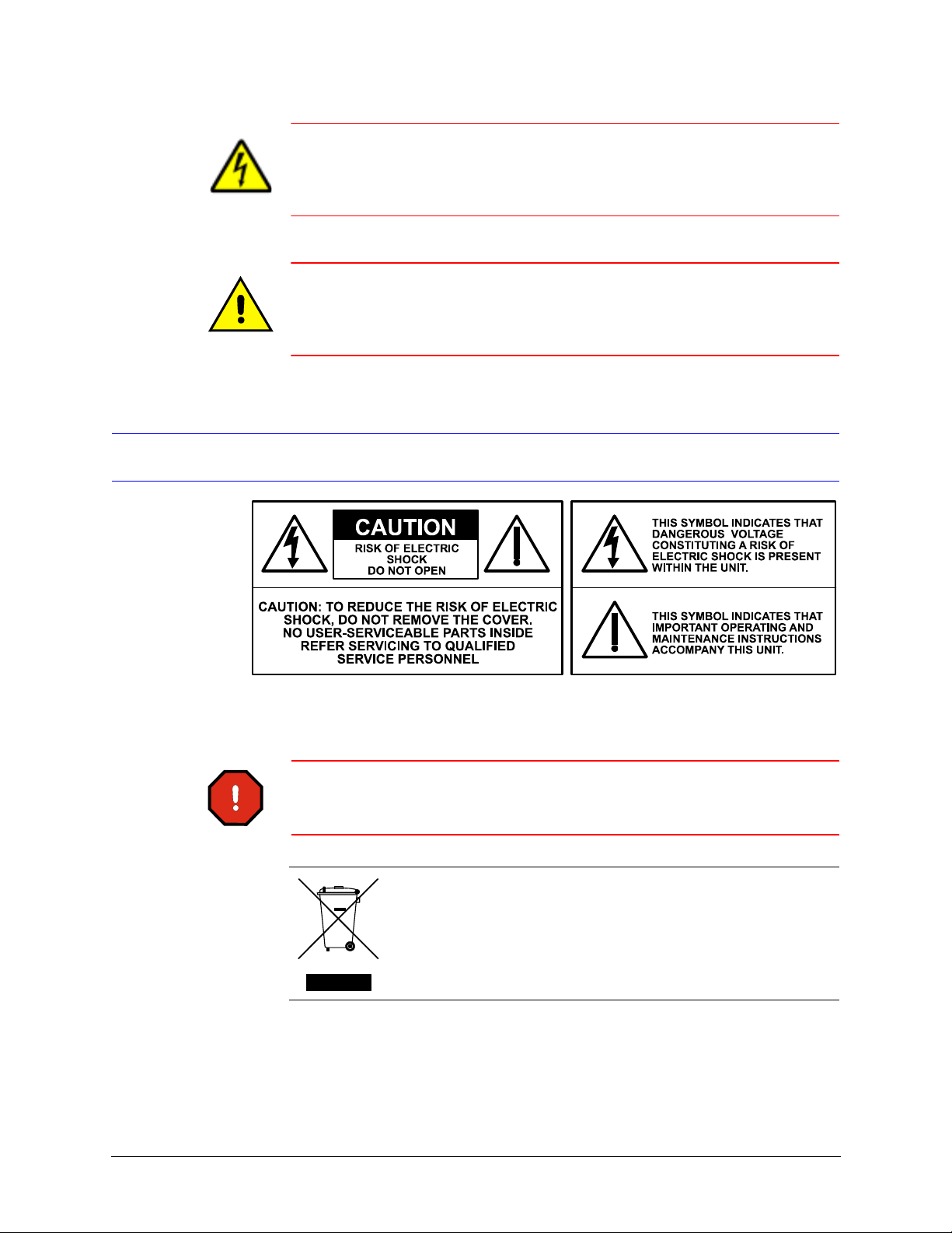
Caution The lightning flash with arrowhead symbol within an equilateral
triangle alerts the user to the presence of uninsulated dangerous
voltage within the enclosure of the product that may be of sufficient
magnitude to constitute a risk of electric shock to the person.
Caution The exclamation point in a yellow equilateral triangle is a Caution.
Failure to take or avoid a specified action could result in loss of data
or damage to equipment and may contain important operating and
maintenance servicing information.
Cautions and Warnings
Installation and servicing should be performed only by qualified and experienced
technicians to conform to all local codes and to maintain your warranty.
WARNING! 12 VDC/24 VAC models require the use of CSA Certified/UL
Listed Class 2 power adapters to ensure compliance with
electrical safety standards.
WEEE (Waste Electrical and Electronic Equipment). Correct disposal
of this product (applicable in the European Union and other European
countries with separate collection systems). This product should be
disposed of, at the end of its useful life, as per applicable local laws,
regulations, and procedures.
12
Page 13

FCC Compliance Statement
Information to the User: This equipment has been tested and found to comply with the
limits for a Class B digital device. Pursuant to Part 15 of the FCC Rules, these limits are
designed to provide reasonable protection against harmful interference in a residential
installation. This equipment generates, uses, and can radiate radio frequency energy and,
if not installed and used in accordance with the instruction manual, may cause harmful
interference to radio communications. However, there is no guarantee that interference
will not occur in a particular installation.
If this equipment does cause harmful interference to radio or television reception, which
can be determined by turning the equipment off and on, the user is encouraged to try to
correct the interference by one of the following measures:
• Reorient or relocate the receiving antenna
• Increase the separation between the equipment and receiver
• Connect the equipment to an outlet on a circuit different from that to which the
receiver is connected
• Consult the dealer or a radio/TV technician for help.
UltraKey Touch Installation and User Guide
Caution Changes or modifications not expressly approved by the party
responsible for compliance could void the user’s authority to operate
the equipment.
Caution Users of the product are responsible for checking and complying
with all federal, state, and local laws and statutes concerning the
monitoring and recording of video and audio signals. Honeywell
shall not be held responsible for the use of this product in violation of
current laws and statutes.
This Class B digital apparatus complies with Canadian ICES-003.
Cet appareil numérique de la Classe B est conforme à la norme NMB-003 du Canada.
Manufacturer’s Declaration of Conformance
North America
The equipment supplied with this guide conforms to UL 60950-1 and CSA C22.2 No.
60950-1.
Document 800-06554 Rev C 13
02/11
Page 14

Europe
The manufacturer declares that the equipment supplied with this guide is compliant with
the essential protection requirements of the EMC directive 2004/108/EC and the Low
Voltage Directive LVD 2006/95/EC, conforming to the requirements of standards EN
55022 for emissions, EN 50130-4 for immunity, and EN 60950 for Electrical Equipment
safety.
Important Safety Instructions
BEFORE OPERATING OR INSTALLING THE UNIT, READ AND FOLLOW
ALL INSTRUCTIONS.
AFTER INSTALLATION, retain the safety and operating instructions for
future reference.
1. HEED WARNINGS - Adhere to all warnings on the unit and in the operating
instructions.
2. INSTALLATION
• Install in accordance with the manufacturer’s instructions.
• Installation and servicing should be performed only by qualified and
experienced technicians to conform to all local codes and to maintain your
warranty.
• Do not install the unit in an extremely hot or humid location, or in a place
subject to dust or mechanical vibration. The unit is not designed to be
waterproof. Exposure to rain or water may damage the unit.
3. POWER SOURCES - This product should be operated only from the type of power
source indicated on the marking label. If you are not sure of the type of power
supplied to your facility, consult your product dealer or local power company.
4. HEAT - Situate the unit away from items that produce heat or are heat sources, such
as radiators, heat registers, stoves, or other products (including amplifiers).
5. WATER AND MOISTURE - Do not use this unit near water or in an unprotected
outdoor installation, or any area classified as a wet location.
6. ATTACHMENTS - Do not use attachments not recommended by the product
manufacturer as they may result in the risk of fire, electric shock, or injury to
persons.
7. ACCESSORIES - Only use accessories specified by the manufacturer.
8. CLEANING - Do not use liquid cleaners or aerosol cleaners. Use a damp cloth for
cleaning.
9. SERVICING - Do not attempt to service this unit yourself as opening or removing
covers may expose you to dangerous voltage or other hazards. Refer all servicing to
qualified service personnel.
10. REPLACEMENT PARTS - When replacement parts are required, be sure the
service technician has used replacement parts specified by the manufacturer or
have the same characteristics as the original part. Unauthorized substitutions may
result in fire, electric shock or other hazards.
14
Page 15

Warranty and Service
Subject to the terms and conditions listed on the Product warranty, during the warranty
period Honeywell will repair or replace, at its sole option, free of charge, any defective
products returned prepaid.
In the event you have a problem with any Honeywell product, please call Customer
Service at 1.800.796.CCTV for assistance or to request a Return Merchandise
Authorization (RMA) number.
Be sure to have the model number, serial number, and the nature of the problem available
for the technical service representative.
Prior authorization must be obtained for all returns, exchanges, or credits. Items shipped
to Honeywell without a clearly identified Return Merchandise Authorization (RMA)
number may be refused.
Finding More Information
UltraKey Touch Installation and User Guide
Refer to the online literature library to access other electronic documents in PDF format
including data sheets, quick references, installation and user guides, specifications,
software and product notices: http://www.honeywellvideo.com. Also see the back cover
for international web sites and contact details.
Typographical Conventions
This document uses the following typographical conventions:
Font What it represents Example
Use of an arrow
between items (>)
Lucida Values of editable fields that are mentioned in the
Use of an arrow between keys or tabs indicates
holding the first key and then pressing the second
key, and then releasing the two keys.
body text of the document for reference purposes,
but do not need to be entered as part of a procedure
Text strings displayed on the screen
Syntax
On the controller, press Alt > Clr to enter
the System Configuration: Standalone
Setting menu.
The Time from field can be set to
Hours:Minute:Seconds.
The message Unauthorized displays.
(object) entered
Document 800-06554 Rev C 15
02/11
Page 16

Font What it represents Example
Swiss721 BT Bold Words or characters that you must type. The word
“enter” is used if you must type text and then press
Enter or Return key.
the
Menu titles and other items you select Double-click Open from the File menu.
Buttons you click to perform actions.
Pressing a key on the keyboard.
Italic Placeholders: words that vary depending on the
situation
Cross-reference to external source Refer to the System Administrator Guide.
Cross-reference within document See Chapter 2, Installation.
Enter the password.
Click Exit to close the program.
Press and hold Login.
user name
16
Page 17
1
UltraKey Touch Overview
The UltraKey Touch keyboard controller (HJC4000) is a replacement for the Honeywell
HJZTP controller and is compatible with Honeywell DVRs and PTZs.
The UltraKey Touch can control the following types of DVRs and PTZs, depending on the
type of connection used:
• DVR: HRDP, HRXD/HRSD, and FUSION DVR.
• PTZ Protocol: Pelco P, Pelco D, Diamond, VCL, and Intellibus.
Shipping Checklist
The following items are included with your UltraKey Touch controller shipment. These
accessories are required for certain kinds of installations. Use a serial port or an Ethernet
RJ45 connection to connect UltraKey Touch to a DVR and PTZ.
Table 1-1 Shipping Checklist
Quantity Part Use for...
1 UltraKey Touch keyboard controller All installations.
1 UltraKey Touch installation and user
guide
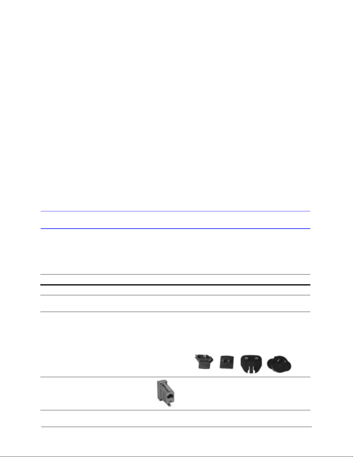
1 box Power adapter with plugs for 100-240
VAC, 12 VDC, 50-60 HZ, 1 A, 12 W
1 Connector adapter, RJ45 to DB9
female, for RS232
Document 800-06554 Rev C 17
02/11
All installations.
Meeting the requirements for the local electrical current being
used. Four models are included:
• CEE 7/16 (Europlug 2.5 A/250V unearthed)
• NEMA 1-15 (North American 15 A/125V ungrounded)
• BS1363 (British 13 A/230-240V 50 Hz earthed and fused)
• CPCS-CCC (Chinese 10 A/250V)/AS 3112; Australian
10 A/240V).
Installations that require backwards compatibility with
a DVR.
Page 18
UltraKey Touch Overview
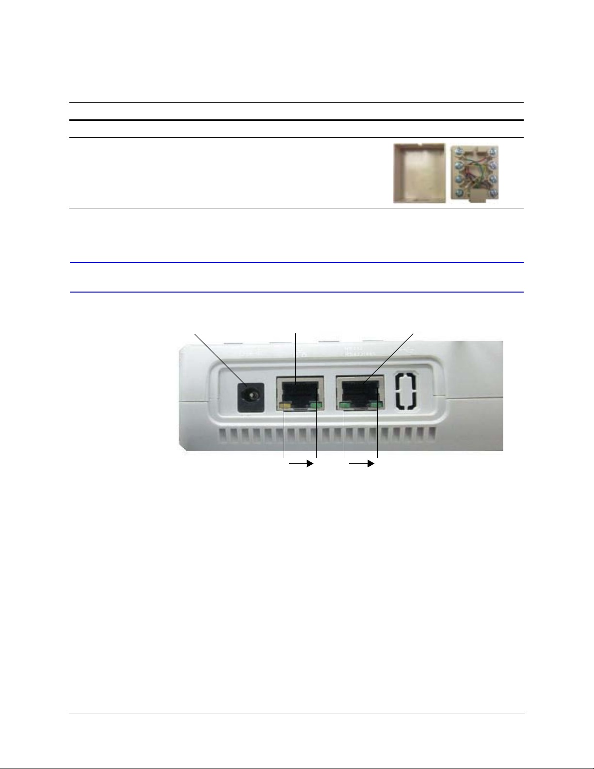
Power RJ45 Ethernet RS232 and RS485 Serial Port
81
Pins are numbered from left to right
81
Table 1-1 Shipping Checklist (cont’d)
Quantity Part Use for...
1 RJ45 network cable, 2 meters All installations.
1 RJ45 box RS485 connection
requirements.
UltraKey Touch Port Connections and Descriptions
Figure 1-1 UltraKey Touch Port Connections
DC Power Port
Supports 12V (±10%) DC/1 A power input. Use the power adapter included with the
shipment and insert one of the four adapters, based on your local power requirements.
Ethernet Port
Ethernet is used to connect to the controller or DVR for controlling and web browser
configuration.
18
Page 19
RS232, RS485 Serial Port
Note These ports are used to connect to DVR RS232/485 or PTZ RS485 ports.
An isolated surge protector is suggested when using RS485 and when cabling between
buildings.
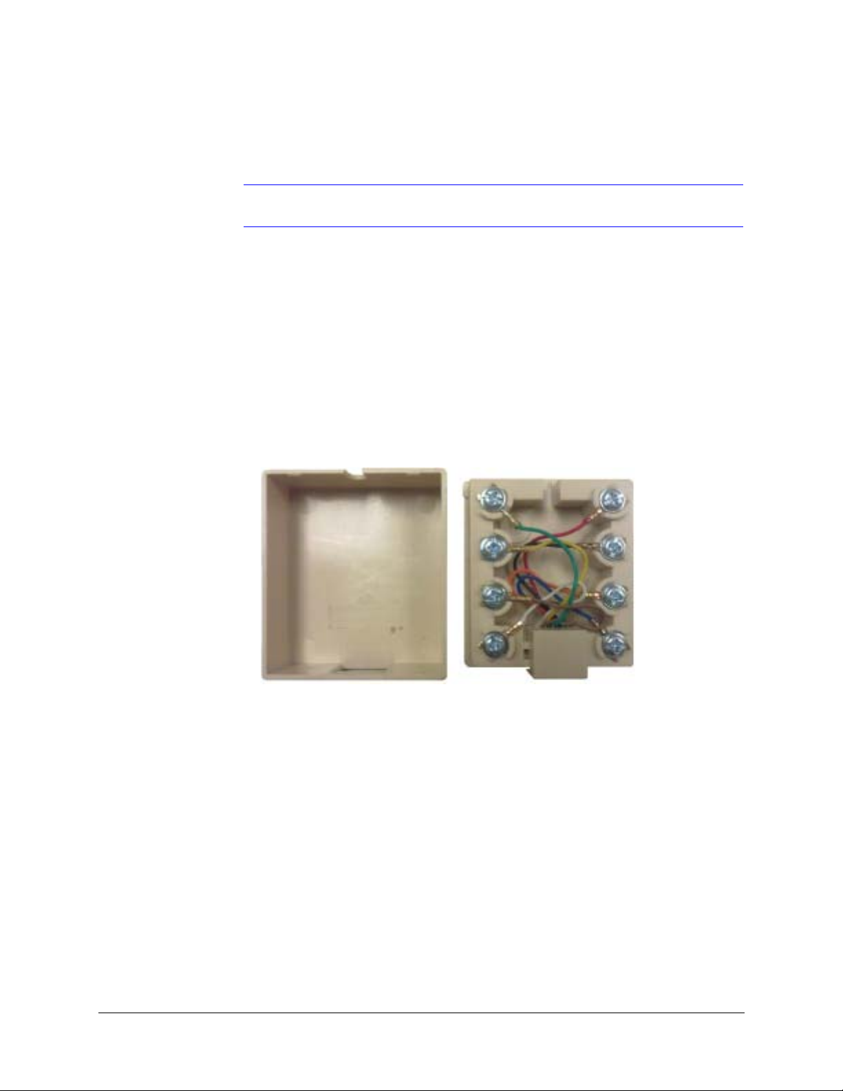
RJ45 Box
Use the terminal box RJ45 port and 8-pin terminal plug as required for compatibility and
connectivity options. It can be used to break out the RJ45 cable when wiring to existing
infrastructure is required.
Figure 1-2 RJ45 Box Front and Back Ports
UltraKey Touch Installation and User Guide
Document 800-06554 Rev C 19
02/11
Page 20

UltraKey Touch Overview
UltraKey Touch Specifications
Table 1-2 UltraKey Touch Specifications
Parameter Value
Power Requirement 10.8 to 13.2 VDC @ 1 Ampere (A)
Connector Types 1 × Ethernet (10Base-T, 100Base-TX) RJ45 with LED
1 × RS232/485 RJ45 with LED
LCD Type: STN, Positive Image
Backlight: Blue-White
Characters: 122 × 32 dots
Compliance EN 55022 for radiated and conducted emissions
Mechanical Dimensions: 16.1” (L) × 8.5” (W) × 4.1” (H)
408 mm (L) × 215 mm (W) × 105 mm (H)
Gross Weight: 7.05 lb. (3.2 kg)
Cover material: ABS + PC (cool gray)
Environment Operating Temperature: 14°F to 131°F (–10°C to +55°C)
Storage Temperature: –40°F to +167°F (–40°C to +75°C)
Humidity: 0 to 95% RH (non-condensing)
20
Page 21

2
Using the UltraKey Touch Controller
You may need to learn how to use the UltraKey Touch both before and after you begin
configuring. This section covers:
• Logging Onto the Controller on page 21
• Using the UltraKey Touch to Navigate the LCD Menus on page 21
Logging Onto the Controller
1. Connect the keyboard with a power adapter (12V [±10%] DC/1 A included).
2. Press Login on the keyboard.
3. Enter the password, 1234.
4. Press Alt>Clr to configure the main menu settings.
Note If an invalid password is entered, a message displays and the controller
buzzes. Repeat the steps to log in.
Using the UltraKey Touch to Navigate the LCD Menus
There are a variety of ways to navigate the LCD menus during configuration as well as
normal operation. See Figure 2-2 for a brief overview of the three main navigation options.
See Table 2-2 for specific methods of navigating the LCD during installation and set up.
Document 800-06554 Rev C 21
02/11
Page 22
Using the UltraKey Touch Controller
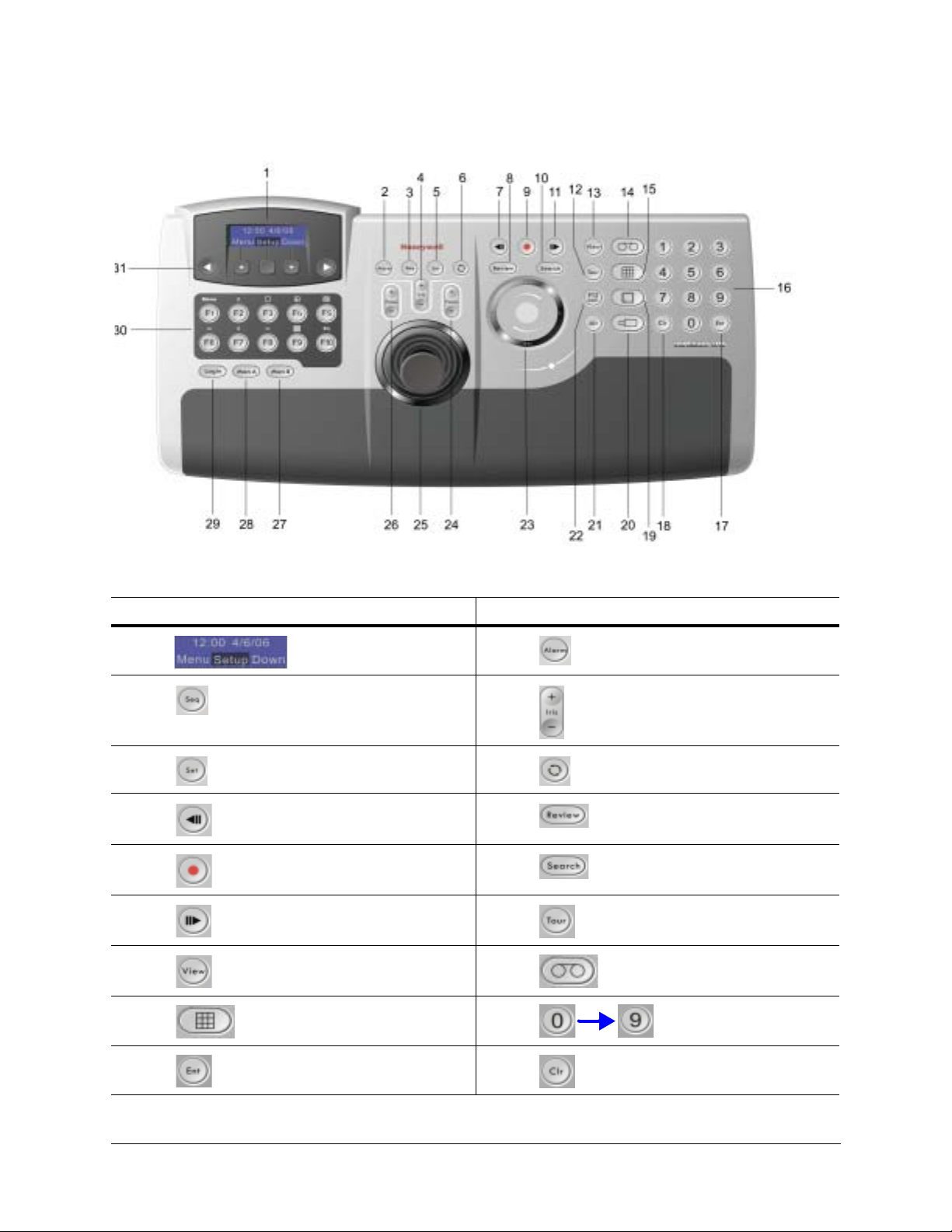
Figure 2-1 UltraKey Touch Controller Keyboard Layout
Table 2-1 UltraKey Touch Controller Keys and Controls
No. Icon Description No. Icon Description
1 LCD screen 2 Alarm key
3 Sequence key 4 Iris open / close key
5 Set key 6 Recycle key
7 Backwards key 8 Review key
9 Stop key 10 Search key
11 Forwards key 12 Tour key
13 View key 14 DVR key
15 Split screen key 16 Number keys
17 Enter key 18 Clear key
22
Page 23
UltraKey Touch Installation and User Guide
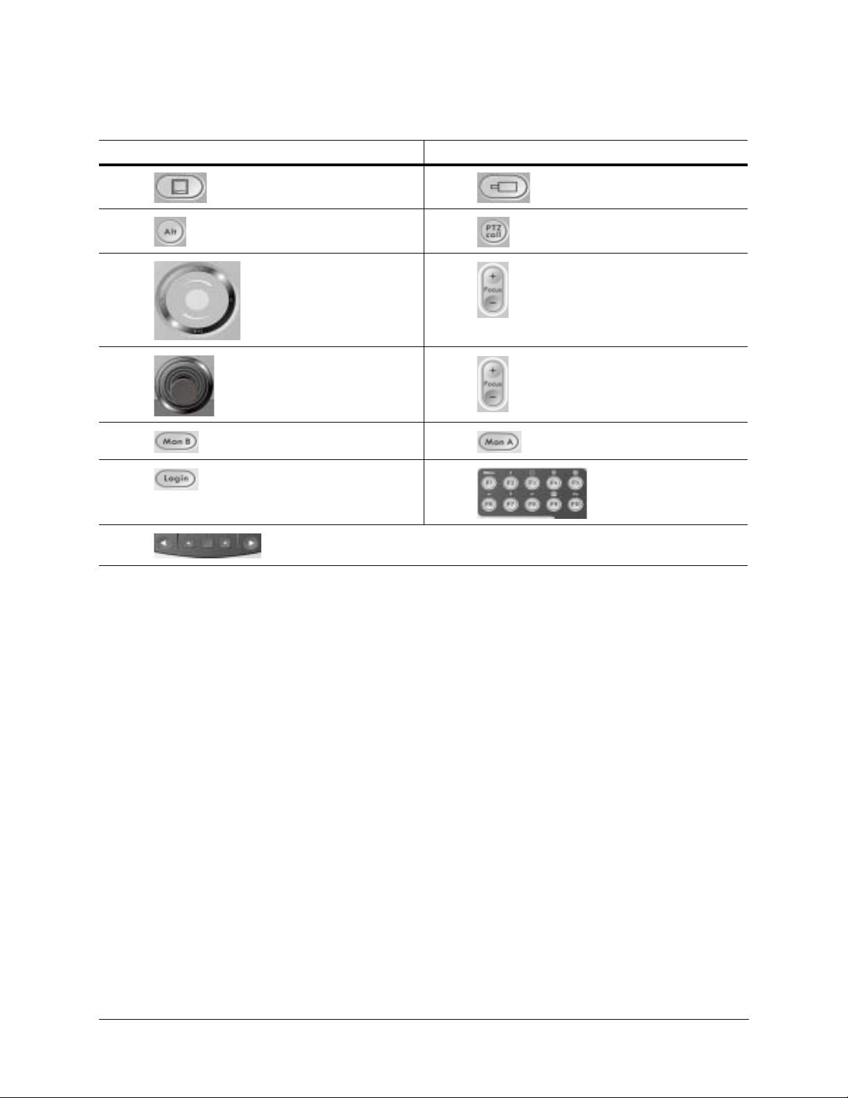
Table 2-1 UltraKey Touch Controller Keys and Controls (cont’d)
No. Icon Description No. Icon Description
19 Monitor key 20 Camera key
21 Alt key 22 PTZ Call key
23 Touch pad slider
Operations with the
touch pad are described
in these instructions as
“Slider_Direction”.
25 Joystick 26 Focus near / far key
27 Monitor B key 28 Monitor A key
29 Login key 30 F1 – F10 keys
31 Left key, Up key, Select key, Down
key and Right key
24 Focus near / far key
Document 800-06554 Rev C 23
02/11
Page 24
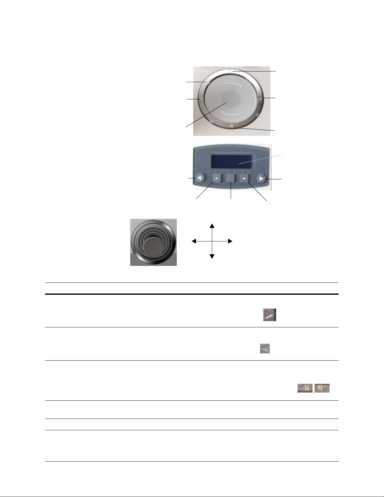
Using the UltraKey Touch Controller
Touch pad slider (used
like a laptop mouse pad)
Right arrow key
Left arrow key
Backward or reverse key
(or down)
Forward key (or up)
Center key is not used
for controlling
Right arrow key
Left arrow key
Up arrow key Down arrow key
Touch Pad and Ring
LCD Keys
Joystick
Move the joystick left and right or
up and down to navigate the menus
Touch pad ring
LCD screen
Figure 2-2 UltraKey Touch Navigation Controls
Table 2-2 LCD Menu Navigation During Setup
Task Options
To confirm a change or enter the
current menu
You can use any of these methods to change or enter the current menu:
•KEYS: Press Ent
•TOUCH PAD RING: Press the right arrow key
•JOYSTICK: Move right
To cancel an operation or return to
the previous level of the menu
You can use any of these methods to cancel or return to the previous menu:
•KEYS: Press Alt > Clr
•TOUCH PAD RING: Press the left arrow key
To view or switch between the
menu items of the same level
•JOYSTICK: Move left
You can use any of these methods to switch between menu items:
• LCD KEYS: Press up / down arrow keys
• TOUCH PAD SLIDER: Rotate your finger clockwise or counterclockwise
•TOUCH PAD RING: Press the forward / backward arrows
•JOYSTICK: Move up / down
To move back through the menus
•KEYS: Press Alt > Clr
one level at a time
To correct errors • KEYS: Press Clr
24
Page 25

3
Connecting UltraKey Touch to a DVR
This section covers:
• Navigating the LCD Configuration Menus on page 26
• Connect to the UltraKey Touch Using the Serial Port (RS232) on page 27
• Connect to the UltraKey Touch Using the Serial Port (RS485) on page 30
• Installing and Configuring an Ethernet Connection on page 35
• Keyboard Configuration for Cascade Linkage (Additional) on page 37
• Configuring UltraKey Touch Using the Web Browser (Optional) on page 39
• Controlling a FUSION DVR on page 43
• Controlling an HRXD/HRSD DVR on page 46
• Controlling an HRDP DVR on page 48
Note For all connections, refer to the applicable DVR user guides for more
information.
This section explains how to connect the UltraKey Touch controller to a DVR and how to
enter the basic configuration settings specific to that DVR. UltraKey Touch can control the
remote DVR through either of the serial port or Ethernet connections. Then you can start
configuring the system. Familiarize yourself with these basic operations:
• To confirm a modification or enter the current menu item you can press: Ent,
Slider_Right (on the touch pad), or move the joystick to the right.
• To cancel an operation or return to the previous level of the menu you can press:
Slider_Left (on the touch pad), Alt > Clr, or move the joystick to the left.
• To view or switch between the menu items of the same level you can press: Slider
Up /Down, the LCD up/down arrow keys, rotate the slider, or move the joystick
up/down.
Document 800-06554 Rev C 25
02/11
Page 26

Connecting UltraKey Touch to a DVR
Right arrow key
Left arrow
key
Up arrow key Down arrow key Numeric keypad
and Ent key
System
Configuration
Data Bit
NetworkSerial Port
Standalone
Settings
DVR / CAM PORT SELECT
HRDP / FUSION
/ HRXD
DVR PTZ
Baud Rate
Parity Stop Bit
IP Address
COM2 (RS232) Show Net Infor Manual Settings DHCP
Serial SettingsDVR Selection
RS232/RS485
Gateway
NetMask
DNS
Basic Set
Navigating the LCD Configuration Menus
Figure 3-1 LCD and LCD Navigation Keys
Figure 3-2 DVR Configuration Menu Tree
26
Page 27

UltraKey Touch Installation and User Guide
Connect to the UltraKey Touch Using the Serial Port (RS232)
Step 1: Connect to the UltraKey Touch Using the Serial Port
Table 3-1 Serial Port Com2 (RS232) Pin Assignments
Serial Port Type Pin Signal
COM2 RS232 4 RXD
5GND
6TXD
Note For a list of cable accessories, see the Shipping Checklist on page 17 and for
port connections see UltraKey Touch Port Connections and Descriptions on
page 18.
1. Select the applicable adapter plug and insert it into the AC adapter. Push to click it
into place.
2. Plug the AC adapter into the controller power port and the adapter into a power
source.
3. Connect the RJ45 network cable to the controller serial port and the connector
adapter.
4. Connect the serial port of the connector adapter to the serial port of the DVR:
• For backwards compatibility with DVRs, a DB9 male adapter is required and
included with your shipment (see Figure 3-3).
• For other DVRs, the installation is a direct connection with the RJ45 network
cable, also included with your shipment.
Note To setup cascade linkage for UltraKey Touch, see Keyboard Configuration for
Cascade Linkage (Additional) on page 37.
Document 800-06554 Rev C 27
02/11
Page 28

Connecting UltraKey Touch to a DVR
Serial Port (RS232)
Network
cable
RJ45 to
DB9F
for RS232
UltraKey Touch
Network Port Network Port
NETWORK
Network
cable
Network
cable
Master Slave1
This indicates that the
keyboard is in PTZ mode.
CAM 001
ST User2
This indicates that the
keyboard is in DVR mode.
CAM 001 DVR 1
ST User2
System Configuration
Standalone Settings
Standalone Set:
DVR
Figure 3-3 Connecting the Controller for DVR Control
Step 2: Configure the UltraKey Touch for DVR Use
Note Set the DVR type in the Ultrakey Touch configuration to be the same as the
connected DVR type. If any other type has been selected, then use the
following procedure to select a different DVR type.
1. Install and connect the controller to a power source, if it is not already connected.
2. Press Login, and then enter the password, 1234.
3. From the home screen, press Alt > Clr to enter the
4. Press Ent and rotate the slider to select DVR.
System Configuration menu. Scroll the slider or rotate
the joystick until System Configuration: Standalone
Settings displays.
28
Page 29

UltraKey Touch Installation and User Guide
DVR Selection
Fusion
DVR Selection
HRDP
DVR Selection
HRXD
Basic Set:
DVR/CAM
Basic Set:
PORT SELECT
Port Select
RS232
Change to DVR mode?
Yes
System Configuration
Serial Port
5. Press Ent to enter the DVR Selection menu. Press the
Slider_Up/Down to select the DVR to control.
6. Press Ent to enter the Basic Set menu. Press the
Slider_Up/Down until the PORT SELECT submenu
displays.
7. Press Ent to enter the Port Select menu, then select
the RS232 protocol to control a DVR. Press Ent or
Slider_Right to confirm.
8. Return to the home screen.
If the keyboard is in PTZ mode after changing to DVR
settings, then the home screen displays this message:
Select Yes or No to change the work mode of the
keyboard.
If the keyboard is in DVR mode after changing to DVR settings, then the home screen
does not display that message.
Step 3: Configure the UltraKey Touch Serial Port Settings
1. Press Alt > Clr to exit from the DVR configuration menu.
2. Before using the UltraKey Touch keyboard to control Fusion/HRXD/HRDP DVRs, it
must be setup to meet the requirements. Set Com2 (RS232) according to Table 3-2.
Table 3-2 Serial Port Com2 (RS232) Configurations
Type RS232
Baud Rate 9600
Parity None
DataBit 8
StopBit 1
3. Press Alt > Clr a second time to enter the System Configuration menu.
4. Rotate the slider to scroll through the options (standalone settings, serial port,
network, language, slider update, cascade linkage, hardware test, about, and restore
default).
5. When you are at the System Configuration: Serial
Port menu, press Ent to enter.
Document 800-06554 Rev C 29
02/11
Page 30

Connecting UltraKey Touch to a DVR
Serial Port:
Com2(RS232)
Serial Settings:
Parity
Serial Settings:
Baud Rate
Serial Settings:
Data Bit
Serial Settings:
Stop Bit
6. Press the Slider_Up/Down or LCD up/down arrow
keys to select Com2 (RS232). Press Ent or
Slider_Right to confirm, and Slider_Left to return.
7. The Serial Setting menu displays. Here you can set the Com2 (RS232) settings for
parity, baud rate, data bit and stop bit:
a. Press the Slider_Right to select Parity. Press Ent
b. Press the Slider_Down or the LCD up/down arrow
c. Press the Slider_Up/down or the LCD up/down
d. Press the down arrow key to select Stop Bit.
8. Press Slider_Left to return to the main menu.
and use the Slider_Up/Down or the LCD up/down
arrow keys to select None. Press Ent to save.
keys to select Baud Rate. Press Ent and use the
up/down arrow keys to select 1200, 1800, 2400,
4800, 9600, 19200, 38400, or 57600. Press Ent to
save.
arrow keys to select Data Bit. Press Ent and use
the Slider_Up/Down to select 7 bit or 8 bit. Press
Ent to save.
Press Ent and use the Slider_Up/Down or the
LCD up/down arrow keys to select 1 bit or 2 bit.
Press Ent to save.
Connect to the UltraKey Touch Using the Serial Port (RS485)
Step 1: Connect to the UltraKey Touch Using the Serial Port
Table 3-3 Serial Port Com1 (RS485) Pin Assignments
Serial Port Type Pin Signal
COM1 RS485 1 T/R+
2T/R–
Note For a list of cable accessories, see the Shipping Checklist on page 17, and for
port connections, see UltraKey Touch Port Connections and Descriptions on
page 18.
1. Select the applicable adapter plug and insert it into the AC adapter. Push to click it
into place.
30
Page 31

UltraKey Touch Installation and User Guide
2. Plug the AC adapter into the controller power port and the adapter into a power
source.
3. Connect the RJ45 network cable to the serial port of the controller and the RJ45 box.
4. Connect the pins (RS485+, RS485–) of the RJ45 box to the pins (T/R+, T/R – ) of the
RS232-RS485 converter using appropriate wire. See Table 3-4 for the RJ45 box pin
assignments.
Table 3-4 RJ45 Box Pin Assignments
Pin Signal
1 RS485+
2 RS485 –
4 RS232 RXD
5GND
6 RS232 TXD
5. Connect the RS232-RS485 converter’s serial port to the DVR’s serial port:
• For backwards compatibility with DVRs, an RS232-RS485 converter is required
(see Figure 3-4).
• To use the controller’s RS485 serial port, an RJ45 box is required.
Note To setup cascade linkage for UltraKey Touch, see Keyboard Configuration for
Cascade Linkage (Additional) on page 37.
Document 800-06554 Rev C 31
02/11
Page 32

Connecting UltraKey Touch to a DVR
Serial Port (RS232)
Serial Port (RS485)
Network
Cable
Serial Port (RS485)
UltraKey Touch
RS232-RS485
Converter
RJ45 Box
Master Slave1
Network
Cable
Network
Cable
Network Port Network Port
NETWORK
54
3
2
1
6
7
8
Figure 3-4 Connecting the Controller for DVR Control Using RS485
Step 2: Configure the UltraKey Touch for DVR Use
32
Note Set the DVR type in the Ultrakey Touch configuration to be the same as the
connected DVR type. If any other type has been selected, then use the
following procedure to select a different DVR type.
1. Install and connect the controller to a power source, if it is not already connected.
Page 33

UltraKey Touch Installation and User Guide
This indicates that the
keyboard is in PTZ mode.
CAM 001
ST User2
This indicates that the
keyboard is in DVR mode.
CAM 001 DVR 1
ST User2
System Configuration
Standalone Settings
Standalone Set:
DVR
DVR Selection
Fusion
DVR Selection
HRDP
DVR Selection
HRXD
DVR Selection
Basic Set:
DVR/CAM
Basic Set:
PORT SELECT
Port Select
RS485
Change to DVR mode?
Yes
2. Press Login, and enter the password, 1234.
3. From the home screen, press Alt > Clr to enter the
System Configuration menu. Scroll the slider or rotate
the joystick until System Configuration: Standalone
Settings displays.
4. Press Ent or rotate the slider to select DVR type.
5. Press Ent to enter the DVR Selection menu. Press the
Slider_Up / Down to select the DVR to control.
6. Press Ent to enter the Basic Set menu. Press the
Slider_Up/Down until the Port Select submenu
displays.
7. Press Ent to enter the Port Select menu, then select
the RS485 protocol to controll the DVR, then press Ent
or Slider_Right to confirm.
8. Return to the home screen.
If the keyboard is in PTZ mode after changing to DVR
settings, then the home screen displays this message:
Select Yes or No to change the work mode of the
keyboard.
If the keyboard is in DVR mode after changing to DVR settings, then the home screen
does not display that message.
Step 3: Configure the UltraKey Touch for Serial Port Settings
1. Press Alt > Clr to exit from the DVR configuration menu.
2. Before using the UltraKey Touch keyboard to control Fusion/HRXD/HRSD/HRDP
DVRs, it must be setup to meet the requirements. Set Com1 (RS485) according to
Table 3-5 on page 34.
Document 800-06554 Rev C 33
02/11
Page 34

Connecting UltraKey Touch to a DVR
System Configuration
Serial Port
Serial Port:
Com1(RS485)
Serial Settings:
Parity
Serial Settings:
Baud Rate
Serial Settings:
Data Bit
Serial Settings:
Stop Bit
Table 3-5 Serial Port Com1 (RS485) Configurations
Type RS485
Baud Rate 9600
Parity None
DataBit 8
StopBit 1
3. Press Alt > Clr a second time to enter the System Configuration menu.
4. Rotate the slider to scroll through the options (standalone settings, serial port,
network, language, slider update, cascade linkage, hardware test, about, and restore
default).
5. When you are at the System Configuration: Serial
Port menu, press Ent to enter.
6. Press the Slider_Up/Down or LCD up/down arrow
keys to select Com1 (RS485). Press Ent or
Slider_Right to confirm, and Slider_Left to return.
7. The Serial Setting menu displays. Here you can set the Com1 (RS485) settings for
parity, baud rate, data bit and stop bit:
a. Press the Slider_Right to select Parity. Press Ent
b. Press the Slider_Down or the LCD up/down arrow
c. Press the Slider_Up/Down or the LCD up/down
d. Press the down arrow key to select Stop Bit.
8. Press Slider_Left to return to the main menu.
and use the Slider_Up/Down or the LCD up/down
arrow keys to select none. Press Ent to save.
keys to select Baud Rate. Press Ent and use the
up/down arrow keys to select 1200, 1800, 2400,
4800, 9600, 19200, 38400, or 57600. Press Ent to
save.
arrow keys to select Data Bit. Press Ent and use
the Slider_Up/Down or the LCD up/down arrow
keys to select 7 bit or 8 bit. Press Ent to save.
Press Ent and use the
Slider_Up/Down or the
LCD up/down arrow keys to select 1 bit or 2 bit.
Press Ent to save.
34
Page 35

UltraKey Touch Installation and User Guide
Installing and Configuring an Ethernet Connection
Note DVR ethernet control is currently unavailable. It will be available in future
releases.
For a list of cable accessories see the Shipping Checklist on page 17, and for port
connections and pin assignments, see UltraKey Touch Port Connections and Descriptions
on page 18. The UltraKey Touch Controller runs TCP/IP keyboard protocol.
Step 1: Connect to the UltraKey Touch Using the Ethernet Port
Table 3-6 RJ45 Ethernet Pin Assignments
Port Pin Signal
RJ45 Ethernet 1 TX +
2TX–
3RX+
6RX–
1. Select the applicable adapter plug and insert it into the AC adapter. Push to click it
into place.
2. Plug the AC adapter into the controller power port and the adapter into a power
source.
3. Plug an RJ45 network cable from the network to the controller Ethernet port (see
Figure 3-5).
4. Connect a DVR to the network. Refer to the applicable DVR Installation Guide for
instructions.
Note To setup cascade linkage for UltraKey Touch, see Keyboard Configuration for
Cascade Linkage (Additional) on page 37.
Document 800-06554 Rev C 35
02/11
Page 36

Connecting UltraKey Touch to a DVR
Network Port Network Port Network Port
NETWORK
Network
Cable
Network
Cable
Network
Cable
Master Slave 1 Slave 2
Network
Port
Network
Cable
UltraKey Touch
System Configuration
Network
Figure 3-5 Ethernet Port Connections to DVR
Step 2: Configure the UltraKey Touch for DVR Use
Note If any mode other than DVR has been selected, then use the procedure in
Step 2: Configure the UltraKey Touch for DVR Use on page 28 to select DVR
mode. Otherwise skip to the next step.
Step 3: Configure the UltraKey Touch Ethernet Connection Settings
1. Press Alt > Clr to enter the System Configuration menu.
2. Rotate the slider or press the LCD up/down arrow keys to scroll through the options
(standalone settings, serial port, network, language, slider update, cascade linkage,
hardware test, about, and restore default).
3. Press Ent when you are at the System Configuration:
Network menu.
36
Page 37

UltraKey Touch Installation and User Guide
Network:
DHCP
Network:
Manual Setting
Network:
Show Net Infor
Network:
IP Address
Network:
GateWay
Network:
NetMask
Network:
DNS
4. Press Slider_Down, the menu displays (one of):
5. Select the Network: Manual Setting menu and press Ent to confirm. Press the
Slider_Up/Down or the LCD up/down arrow keys to setup the UltraKey Touch
network parameters (IP Address, Gateway, NetMask and DNS):
a. Press the Slider_Up/Down
arrow keys to scroll through the menu options and
select IP Address. Press Ent. Using the numeric
keypad, enter an IP address. Press Ent to save.
IPAddr Changed displays on the LCD menu. Press the Slider_Up/Down or the
LCD up/down arrow keys to select Yes to save or No to cancel. Press Ent.
b. Press the Slider_Up/Down or the LCD up/down
arrow keys
select Gateway. Press Ent. Using the numeric
keypad, enter a Gateway value, as required. Press
Ent to save.
GW Changed displays on the LCD menu. Press the Slider_Up/Down
up/down arrow keys to select Yes to save or No to cancel. Press Ent.
c. Press the Slider_Up/Down or the LCD up/down
arrow keys to scroll through the menu options and
select NetMask. Press Ent. Using the numeric
keypad, enter a NetMask value, as required. Press
Ent to save.
NetMsk Changed displays on the LCD menu. Press the Slider_Up/Down
LCD up/down arrow keys to select Yes to save or No to cancel. Press Ent.
d. Press the Slider_Up/Down or the LCD up/down
arrow keys to scroll through the menu options and
select DNS. Press Ent. Using the numeric keypad,
enter a DNS value, as required. Press Ent to save.
DNS Changed displays on the LCD menu. Press the Slider_Up/Down or the
LCD up/down arrow keys to select Yes to save or No to cancel. Press Ent.
6. If other changes are required from this menu (language, slider update, cascade
linkage, hardware test, and about) see System Administration and Troubleshooting on
page 65. Otherwise the installation and configuration is complete.
to scroll through the menu options and
or the LCD up/down
or the LCD
or the
Keyboard Configuration for Cascade Linkage (Additional)
Note No entry is required in the baud rate field for Ethernet connected controllers.
Document 800-06554 Rev C 37
02/11
Page 38

Connecting UltraKey Touch to a DVR
System Configuration
Cascade Linkage
Cascade Linkage:
KBD Mode
Cascade Linkage:
IP Address
Network:
IP Address
Note The IP address of the master or slave keyboard is both referred to IP address
1. Press Alt > Clr and scroll with the slider. The Cascade
Linkage menu appears.
2. In cascade mode, you can set the keyboard status
(such as master or slave), and the cascade IP address if its status is set as “slave”.
3. Press the Slider_Right to enter the Cascade Linkage menu.
There are two menu items: KBD Mode and IP Address.
4. Press the Slider_Up/Down to scroll to KBD Mode and press Ent.
Set the keyboard as master or slave, and press
Slider_Right or Ent to confirm.
in the Network menu.
• In the KBD Mode menu, the keyboard can be set as master or slave;
• In the IP Address menu, when the keyboard is in slave statues, you should
set this cascade IP address to match the master’s IP address.
5. For a slave keyboard, press the Slider_Left to return to
the Cascade Linkage menu. Press the
Slider_Up/Down until the IP Address menu displays,
then set this cascade IP address to match the master’s
IP address.
6. For a master keyboard, this cascade IP address is
invalid. Set the master’s IP address in the Network
menu.
7. Press Ent. Rotate the slider and use the numeric keypad to enter an IP address, as
required.
Note The slave keyboard’s cascade IP address in the Cascade Linkage submenu
must be the same as the master keyboard’s IP address in the Network
submenu. The master keyboard’s cascade IP address in the Cascade
Linkage submenu is invalid.
8. Press Ent
to confirm.
38
Page 39

UltraKey Touch Installation and User Guide
Configuring UltraKey Touch Using the Web Browser (Optional)
Logging into the Web Browser
1. Input, navigate to, or copy and paste, the applicable IP address into your web
browser:
• LAN connections: for example, http://192.168.1.9 (default).
• Crossover cable connections - static address: http://192.168.1.9 (default).
2. Enter Administrator (case sensitive) in the User Name field.
3. Enter 1234 (default) in the Password field.
4. Click Login.
Figure 3-6 UltraKey Touch Login Page
Step 1: Configure UltraKey Touch to Standalone Mode
1. Log into the web browser (see Logging into the Web Browser on page 39).
2. From the top menu, click the Configuration tab (see Figure 3-7).
3. From the side menu, click the System Configurations tab.
4. Select Standalone from the System Mode drop-down list.
5. Select English from the System Language drop-down list.
6. Click Apply to save the configuration, Cancel to exit without saving, or Default to
restore all factory default values.
Document 800-06554 Rev C 39
02/11
Page 40

Connecting UltraKey Touch to a DVR
Top menu
Side menu
Figure 3-7 System Configuration Tab
Step 2: Standalone Configuration for DVR Settings
1. From the side menu, click Standalone Configuration (see Figure 3-8).
2. Set the DVR type to be the same as the controlled DVR in the DVR Type drop-down
list.
Select DVR type as Fusion, HRXD/HRSD, or HRDP.
3. Cascade Mode settings are used for the Cascade Linkage of keyboards.
a. Set the Ultrakey Touch as Master or Slave in the Mode drop-down list.
b. Set the IP of the Master UltraKey Touch in the Master IP Address drop-down list.
4. Set the Address, Name, and Protocol Type for the controlled PTZ in the PTZ window
area.
5. Click Apply to save the configuration, Cancel to exit without saving, or Default to
restore all factory default values.
40
Page 41

UltraKey Touch Installation and User Guide
Side menu
Figure 3-8 Standalone Configuration for DVR Tab
Step 3A: Configure the Controller for a Serial Port Connection
1. From the side menu, click Serial Port Configuration (see Figure 3-9).
2. In the Serial Port1 Settings window area, select the appropriate value in the
drop-down lists from each of the following fields:
• Baud Rate: 1200, 1800, 2400, 4800, 9600, 19200, 38400, or 57600 bps.
• Parity: none, even, or odd.
• Stop Bits: 1 or 2 bits.
• Data Bits: 7 or 8 bits.
• Serial Mode: RS232 or RS485.
3. If required, repeat step 2 for serial Com1/Com2 settings.
4. Click Apply to save the configuration, Cancel to exit without saving, or Default to
restore all factory default values.
Document 800-06554 Rev C 41
02/11
Page 42

Connecting UltraKey Touch to a DVR
Side menu
Figure 3-9 Serial Port Configuration Tab
Step 3B: Configure the Controller IP for an Ethernet Connection
1. From the side menu, click IP Configuration (see Figure 3-10).
2. Enter IP Address, Subnet Mask, Gateway and DNS values in each of the fields.
3. Click Apply to save the configuration, Cancel to exit without saving, or Default to
restore all factory default values.
42
Page 43

Figure 3-10 IP Configuration Tab
Side menu
Standalone Set:
DVR
DVR Selection:
FUSION
UltraKey Touch Installation and User Guide
Controlling a FUSION DVR
Step 1: Connection
See Figure 3-3 on page 28, and Figure 3-4 on page 32.
Step 2: Select DVR Type
1. Press Alt + Clr to enter the Standalone Settings menu. See the menu tree (see
Figure 3-2 on page 26) to select the DVR.
2. Press the Slider_Right and rotate the slider in the DVR
TYPE menu. The following LCD screens are displayed.
3. Press the Slider_Right to select FUSION.
Document 800-06554 Rev C 43
02/11
Page 44

Connecting UltraKey Touch to a DVR
Basic Set:
DVR/CAM
CAM 1
DVR 1
Press... To display in... Press... To display in...
4+1+Split 4A grid 9+1+Split 9A grid
4+2+Split 4B grid 9+2+Split 9B grid
4+3+Split 4C grid 1+6+Split 16 grid
4+4+Split 4D grid
Step 3: DVR and Camera Connection
1. Press the Slider_Right to enter the Basic Set menu.
2. Press Ent. Rotate the slider to select the Camera (from
1 to 128). Press the Slider_Right to select the DVR as
1. Press the Slider_Left to save the configuration and
exit the menu.
3. The keyboard can control 1, 4, 9, and 16-channel DVRs. For example, if a system has
33 cameras with:
• DVR 1, a 4-channel DVR connected to cameras 1 through 4 inclusive
• DVR 2, a 4-channel DVR connected to cameras 5 through 8 inclusive
• DVR 3, a 16-channel DVR connected to cameras 9 through 24 inclusive
• DVR 4, a 9-channel DVR connected to cameras 25 through 33 inclusive
Then this system would be shown as in Table 3-7, below:
Table 3-7 DVR Control CAM
CAM 1 ~ 4 DVR 1 4-channel DVR (DVR 1)
CAM 5 ~ 8 DVR 2 4-channel DVR (DVR 2)
CAM 9 ~ 24 DVR 3 16-channel DVR (DVR 3)
CAM 25 ~ 33 DVR 4 9-channel DVR (DVR 4)
Operating a Fusion DVR
Table 3-8 Operating a Fusion DVR
You want to... Do this...
Select a DVR Press a number + DVR, or DVR + a number + Ent.
Use the Display function to
program DVRs to rotate different
Live or Search display grids.
For example: 4 camera (A), 4
camera (B), 4 camera (C), 4
camera (D), 9 camera (A), 9
camera (B), and 16 camera grid
screens display.
Press Split on the keyboard to rotate to the DVR’s next grid display from
the current grid display.
For example: if the current grid display is 4 camera (B) and you press Split,
the DVR will change to the 4 camera (C) grid display.
OR
Press one or two of the number keys followed by Split to force the DVR to
change into any kind of grid display (see the table below).
44
Page 45

UltraKey Touch Installation and User Guide
Press... To... Press... To...
F2 Up F8 Right
F7 Down Ent Confirm
F6 Left Clr Esc
Table 3-8 Operating a Fusion DVR
You want to... Do this...
Auto Sequence Press Seq to toggle Auto Sequence on a Fusion DVR.
Toggle Relay (alarm output) on a
specified channel
Instant Record Press the number key, which represents a specific channel, followed by
Switch to Full Screen Display Press Ent.
Select a Camera to Display Press number + Camera, or Camera + number + Ent, or number+Ent.
Reverse Play Press Backward to make a DVR play backwards while searching.
Stop Press Stop to halt video playing on a DVR.
Play Press Review to make a DVR play forwards while searching.
Adjust the forward or backward
playback speed
Zoom (if only one camera is
selected in Search)
Search Date Press Search to display the Search menu for configuring the date, month
Navigate the Search date set menu See the table below for the keyboard operations for navigating the Search
Press the number key (less than 5), then Alarm.
the Recycle key to toggle instant recording on that specified channel.
Rotate your finger on the touch pad slider.
Press Set to adjust the zoom level from level 1 to level 5.
and time for playback.
When the DVR is in search play mode and the channel to play has been
set, users can press F1 to display the Search menu.
Date Set menu.
Display video of the previously
selected camera
Display the 4-camera split screen Press F4
Display the 9-camera split screen Press F5
Display the 16-camera split screen Press F9
Note For more information about PTZ operation for Fusion, see Step 2: Camera
Document 800-06554 Rev C 45
02/11
Press F3
Selection on page 60 and Operating a PTZ Camera on page 60 (excluding
PTZCALL).
Page 46

Connecting UltraKey Touch to a DVR
DVR Selection:
HRXD
Press... To...
Slider_Up or F2 Move up
Slider_Down or F7 Move down
Slider_Left or F6 Move left
Slider_Right or F8 Move right
Ent Select an option.
F1 Exit the current menu. If the user
presses F1 when in the Setup
screen, the DVR exits the menus
and returns to normal operation.
Also used to enter the menu.
Controlling an HRXD/HRSD DVR
Step 1: Connection
See Figure 3-3 on page 28, and Figure 3-4 on page 32.
Step 2: Keyboard Setup for Connection
HRXD DVR setup is the same as the FUSION DVR setup
except that you select HRXD (see Controlling a FUSION DVR
on page 43).
Operating an HRXD DVR
You want to... Do this...
Select a DVR Press a number key + DVR, or DVR + number key + Ent.
Enter numbers for a password Press and hold the Alt key and then press the number keys.
Access the DVR menus Press F1 to open the password screen. Press and hold the
Navigate the DVR menus Use the following keys.
Table 3-9 Operating an HRXD DVR
Alt key, and enter the password. Then press Ent to access
the DVR setup menu.
Cycle through the display settings Press Split to select the next display setting (in the cycle of
46
4x4, 3x3, 2x2 and PIP).
Page 47

Table 3-9 Operating an HRXD DVR
You want to... Do this...
UltraKey Touch Installation and User Guide
Cycle through the cameras that are displayed
when viewing 2x2 and 3x3 displays
Set the screen layout of the multi-cameras,
and select a camera to be displayed in the
cameo
Start and stop a sequence Press Seq to put the DVR output into a sequence (the
Freeze and unfreeze the current display Press F10.
Select a camera Press number keys (to enter a valid camera number) +
Reset an active alarm If an alarm is active, press Alarm to reset the DVR output
Display the alarm event log If the DVR is in live monitoring mode (and no alarm is
Use the Slider_Left/Right.
Press Ent, then Slider_Up, Slider_Down, Slider_Left or
Slider_Right to select an active camera (highlight box
displayed). Press a number key + Camera, or Camera +
number + Ent, or number + Ent.
sequence depends on the current display mode and
setup). If the key is pressed again, the sequence will stop
(displaying the current step in the sequence).
Camera, or Camera + number + Ent, or number + Ent.
This will select a camera (identified by the number) for
full-screen display on the DVR output. This also selects the
associated DVR.
(internal buzzer included).
active), press Alarm to display the event log. Once the
event log is open, navigate through it in the same way as
described in Navigate the DVR menus, on page 46.
Note If user password is enabled on the DVR, then pressing Alarm will cause a user password screen to
display. If a user password is required, then enter the password as described on page 46.
Display a camera on the spot monitor Press Monitor+number+Ent to choose a Spot Monitor,
then number + Camera, or Camera + number + Ent, or
number + Ent to select the camera that displays on that
spot monitor.
Apply the spot monitor to a camera sequence Press Monitor+number+Ent to choose a Spot Monitor,
and then Seq to apply the spot monitor to a camera
sequence.
Instant record or panic record Press Recycle to enable/disable the Panic Recording on
specified channel.
Open/close the Search menu Press Search to bring up the Search menu. Press the key
again to exit the Search menu.
Play video Press Review to playback or pause the DVR video.
Switch between live monitoring and pause Press the Stop key to switch between the live monitoring
and paused states.
Go to the next frame when the DVR is paused Rotate the slider clockwise to show the next frame.
Go to the previous frame when the DVR is
paused
Fast forward the DVR playback Press Forward.
Rewind DVR playback Press Backward.
Rotate the slider counterclockwise to show the previous
frame.
Document 800-06554 Rev C 47
02/11
Page 48

Connecting UltraKey Touch to a DVR
DVR Selection:
HRDP
Table 3-9 Operating an HRXD DVR
You want to... Do this...
Zoom in on an image on the screen Press Set.
To control PTZ domes Press Alt > Set to enable HJC4000 to control PTZ domes.
Note For more information about PTZ operation for HRXD, see Step 2: Camera
Selection on page 60 and Operating a PTZ Camera on page 60 (excluding
PTZCALL).
Controlling an HRDP DVR
Step 1: Connection
See Figure 3-3 on page 28, and Figure 3-4 on page 32.
Step 2: Keyboard Setup for Connection
HRDP DVR setup is the same as the FUSION DVR setup
except that you select HRDP (see Controlling a FUSION DVR
on page 43).
Operating an HRDP DVR
Table 3-10 Operating an HRDP DVR
You want to... Do this...
Select a DVR Press a number key + DVR, or DVR + number + Ent.
Note Common operations of the HRDP and Fusion DVRs are not listed here.
Cycle through different displays in Live mode Press the Display button to cycle through the different
displays in live mode. You cannot enter numbered inputs.
48
Enter the DVR Setup menu Press the Monitor button.
Page 49

UltraKey Touch Installation and User Guide
Press... To... Press... To...
F2 Up F8 Right
F7 Down Ent Confirm
F6 Left Clr Esc
Table 3-10 Operating an HRDP DVR
You want to... Do this...
Auto Sequence Press Seq to cycle through the remaining channels within
the display mode or rotate the display configuration. For
both live viewing and searching, in PTZ mode, Seq can be
used to enter PRESET mode.
Configure Alarm Out settings Not supported.
Instant record Press Recycle to start instant recording of all channels.
Display a selected camera in full screen mode Press a number key + Camera, or Camera + number +
Ent, or number + Ent.
Toggle between Live view and Search Press Search.
Enter FOCUS mode while in PTZ mode Press Search.
Play videos in reverse Press F6 or Reverse. You can continuously press Reverse
to change the playback speed.
Stop playback Not supported.
Play recorded videos Press F8 or Forward. You can continuously press Forward
to change the playback speed.
Zoom in on video Image Zoom function is not supported in Live or Search
mode. But when an HRDP is in PTZ mode, press the Set key
to enter ZOOM mode.
Enter Backup mode while in Live or Search
mode
Enter the express search mode Press F1 while in Search mode.
Navigate the menu See the table below for the keyboard operations for
Cycle through different displays in Live mode Press F3, F4, F5, F9.
Start Panorama Search in playback mode Press F2.
Start Smart Search in playback mode Press F7.
Enter PTZ mode Press F10.
Exit PTZ mode Press Clr.
Press Set.
navigating menus.
Document 800-06554 Rev C 49
02/11
Page 50

Connecting UltraKey Touch to a DVR
Press... To... Press... To...
F2 Tilt up F6 Pan left
F7 Tilt down F8 Pan right
Table 3-10 Operating an HRDP DVR
You want to... Do this...
To control PTZ cameras Use the joystick or see the table below for the keyboard
operations for contolling PTZ domes.
Note You cannot use the keyboard to stop panning or
tilting.
Note The Iris, Focus, and Preset Store (View+Num+Set) keys are not
supported. The Preset Call (View+Num+Ent or Num+View) key is
supported.
Joystick Controls
Table 3-11 Joystick Controls
Control Function
Joystick up/down Navigation mode: move the cursor up/down.
Playback mode: start a Panorama/Smart search.
PTZ mode: same functions as for a Fusion DVR.
Joystick left/right Navigation mode: move the cursor left/right.
Playback mode: play recorded videos forwards or reversed.
PTZ mode: same functions as for a Fusion DVR.
Joystick zoom in Live mode: starts playback of the latest recording.
PTZ mode: adjust zoom and focus on a PTZ channel.
Playback mode: cycle the playback speed from 1X to 8X.
Playback-pause mode: cycle the playback speed from 1/2X
to 1/8X.
Joystick zoom out Live mode: switches to PTZ mode.
PTZ mode: adjust zoom and focus on a PTZ channel.
Playback mode: cycle the reverse playback speed from 1X
to 8X.
Playback-pause mode: cycle the reverse playback speed
from 1/2X to 1/8X.
50
Page 51

4
Installing UltraKey Touch with PTZ
This section covers:
• Navigating LCD Configuration Menus on page 51
• Installing and Configuring a Serial Connection on page 52
• Configuring UltraKey Touch Using the Web Browser (Optional) on page 56
• Controlling PTZs on page 59
Note For all installations, refer to the applicable PTZ installation or user guides for
more information.
This section explains how to connect the UltraKey Touch controller to a PTZ camera and
how to enter the basic configuration settings specific to PTZs. For other user
configurations see the table of contents.
Navigating LCD Configuration Menus
Note See Using the UltraKey Touch to Navigate the LCD Menus on page 21 for
detailed instructions for other ways to navigate or System Administration
Using the Controller LCD on page 65 for configuration menu navigation.
Document 800-06554 Rev C 51
02/11
Page 52

Installing UltraKey Touch with PTZ
System
Configuration
Data Bit
NetworkSerial Port
Standalone
Settings
Protocol /
Address / Name
PTZ DVR
Baud Rate
Parity Stop Bit
IP Address
COM1 (RS485) Show Net Infor Manual Settings DHCP
Serial SettingsPTZ Settings
Gateway
NetMask
DNS
Figure 4-1 PTZ Configuration Menu Tree
Installing and Configuring a Serial Connection
Step 1: Connect to the UltraKey Touch Serial Port
Note For a list of accessories see Shipping Checklist on page 17 and for port
connections see UltraKey Touch Port Connections and Descriptions on page
18.
Note COM1 (RS485) are configured using the System Configuration menu. See
Table 4-1 below. For connection between Ultrakey Touch and PTZ, refer to
Figure 4-2. Certain settings should be done before using the direct control of
a PTZ with Ultrakey Touch.
Table 4-1 Serial Port COM1 Pin Assignments
52
Serial Port Type Pin Signal
COM1 RS485 1 T/R +
2T/R –
Page 53

UltraKey Touch Installation and User Guide
Serial Port (RS485)
4
3
2
1
5
6
7
8
RJ45 box
Network
cable
RS485
UltraKey Touch
Network Port Network Port
NETWORK
Master
Slave 1
Network
cable
Network
cable
RS485 Serial Port Connecting to a PTZ using the RJ45 Box:
1. Select the applicable adapter plug and insert it into the AC adapter. Push to click it
into place. See Figure 4-2.
2. Connect an RJ45 network cable from the RJ45 Box port to the controller serial port.
3. Connect the pin (RS485+, RS485–) of the RJ45 Box to a PTZ using an appropriate
wire.
Note To setup Cascade Linkage for UltraKey Touch, see Keyboard Configuration
for Cascade Linkage (Additional) on page 37.
Figure 4-2 RS485 Serial Port Connection PTZ by RJ45 Box
Table 4-2 RJ45 Box Pin Assignments
Pin Signal
1 RS485+
2 RS485–
4 RS232 RXD
5GND
6 RS232 TXD
Document 800-06554 Rev C 53
02/11
Page 54

Installing UltraKey Touch with PTZ
This indicates that the
keyboard is in PTZ mode.
CAM 001
ST User2
This indicates that the
keyboard is in DVR mode.
CAM 001 DVR 1
ST User2
System Configuration
Standalone Setting
Standalone Set:
PTZ
PTZ Setting:
Protocol
PTZ Setting:
Name
PTZ Setting:
Address
Change to PTZ mode?
Yes
Step 2: Configure the Controller for PTZ
Note In the Standalone main menu, press Ent, and rotate the slider to enter PTZ
settings or press PTZ. You can set the PTZ Name, Address, and Protocol.
1. Install and connect the controller to a power source, if it is not already connected.
The UltraKey Touch LCD displays.
2. Press the Login key and enter the password: 1234. Press Ent to confirm.
3. From the home screen, press Alt > Clr to enter the
System Configuration menu.
4. Scroll to and select Standalone Settings. Press
Slider_Right or Ent to enter the Standalone Set menu.
5. Rotate the slider to select the PTZ, press Slider_Right
to enter PTZ settings.
6. Press Slider_Down or LCD arrow key up/down, and
the following figure is displayed on LCD screen:
a. Use the Slider_Up/Down keys to scroll to different
controller protocols. Press Ent to save.
b. Use the Slider_Up/Down keys to scroll to change
the name of the controller. Press Ent to save.
c. Use the Slider_Up/Down keys to scroll to an
address between 1 and 128 to assign to the
controller. Press Ent to save.
Return to the home screen.
If the keyboard is in DVR mode after changing to PTZ
settings, then the home screen displays this message:
Select Yes or No to change the work mode of the keyboard.
If the keyboard is in PTZ mode after changing to PTZ settings, then the home screen does
not display that message.
Step 3: Configure Serial Port of the Controller
1. Press Alt > Clr to enter the System Configuration top menu.
54
Page 55

UltraKey Touch Installation and User Guide
System Configuration:
Serial Port
Serial Port
Com1(RS485)
Serial Setting:
Parity
Serial Setting:
Baud Rate
Serial Setting:
Data Bit
Serial Setting:
Stop Bit
2. Press the Slider_Up/Down or LCD up/down arrow key to scroll through the options
(standalone settings, serial port, network, language, slider update, cascade linkage,
hardware test, about, and restore default).
3. When you are at the System Configuration: Serial Port menu, press Ent.
4. Use the Slider_up/down to select Com1(RS485). Set Com1 according to the table
below.
Type RS485
Baud Rate 9600
Parity None
DataBit 8
StopBit 1
5. Press Slider_Up/Down keys or LCD up/down arrow key to select COM1. Press Ent,
the Serial Setting menu displays where you can set these COM1 settings: parity,
baud rate, data bit and stop bit.
a. Press LCD up/down arrow key to select Parity.
Press Ent and use the Slider_Up/Down keys to
select None, Odd, or Even. Press Ent to save.
b. Press LCD up/down arrow key to select
BaudRate. Press Ent and use Slider_Up/Down
keys to select 1200, 1800, 2400, 4800, 9600,
19200, 38400, or 57600. Press Ent to save.
c. Press LCD up/down arrow key to select DataBit.
Press Ent and use Slider_Up/Down to select 7 bit
or 8 bit. Press Ent to save.
d. Press LCD up/down arrow key to select StopBit.
Press Ent and use Slider_Up/Down to select 1 bit
or 2 bit. Press Ent to save.
6. If other changes are required from this menu (language, slider update, cascade
linkage, hardware test, about, restore default), see System Administration and
Troubleshooting on page 65. Otherwise the installation and configuration is complete.
7. After finishing keyboard setup, press Slider_Left to return to the main menu.
8. To select a camera for control, press a number (1–128) + Camera, or Camera +
number + Ent, or number + Ent.
Document 800-06554 Rev C 55
02/11
Page 56

Installing UltraKey Touch with PTZ
Configuring UltraKey Touch Using the Web Browser (Optional)
Logging into the Web Browser
1. If not already done, navigate to, or copy and paste, the applicable IP address into
your web browser:
• LAN connections: for example, the default IP is http://192.168.1.9.
• Crossover cable connections - static address: http://192.168.1.9.
2. Enter Administrator (case sensitive) in the User Name field (see Figure 4-3).
3. Enter 1234 (default) in the Password field.
4. Click Login.
Figure 4-3 UltraKey Touch Login page
Step 1: Configure UltraKey Touch to System Configurations
1. Log into the web browser.
2. From the top menu, click the Configuration tab.
3. From the side menu, click the System Configurations tab.
4. From the System Mode drop-down list, select Standalone (see Figure 4-4).
5. From the System Language drop-down list, select English.
6. Click Apply to save the configuration, Cancel to exit without saving or Default to
restore all factory default values.
56
Page 57

Figure 4-4 System Configuration Tab
UltraKey Touch Installation and User Guide
Step 2: Standalone Configuration for PTZ Settings
1. From the side menu, click Standalone Configuration (see Figure 4-5).
2. Under DVR Setting drop-down list, set DVR type as same as the controlled DVR.
3. Under Cascade Mode, the settings are used for cascading linkage of keyboards.
a. Under Mode drop-down list, select Master or Slave for Ultrakey Touch.
b. Under Master IP Address drop-down list, set the IP of the Master UltraKey
Touch.
4. Under PTZ, set the address, name, and protocol for the controlled PTZ.
5. Under Protocol Type drop-down list, select Diamond, PelcoD, PelcoP, VCL,
IntelliBUS protocol consistant with the controlled Ultrakey Touch.
6. Click Apply to save the configuration, Cancel to exit without saving, or Default to
restore all factory default values.
Document 800-06554 Rev C 57
02/11
Page 58

Installing UltraKey Touch with PTZ
Figure 4-5 Standalone Configuration for PTZ Tab
Step 3: Configure the Controller for a Serial Port Connection
1. From the side menu, click Serial Port Configuration (see Figure 4-6).
2. Under Serial Com1 Settings, select the following from each drop-down list, as
required:
• Baud Rate: 1200, 1800, 2400, 4800, 9600, 19200, 38400, or 57600 bps
• Parity: none, even or odd
• Stop Bits: 1 or 2 bits
• Data Bits: 7 or 8 bits
• Serial Mode: RS485
3. Click Apply to save the configuration, Cancel to exit without saving or Default to
restore all factory default values.
58
Page 59

UltraKey Touch Installation and User Guide
Figure 4-6 Serial Port Configuration Tab
Controlling PTZs
Step 1: Keyboard Setup
For a connection between Ultrakey Touch and a PTZ, see Figure 4-2.
Certain settings should be done before using the direct control of PTZ with Ultrakey Touch.
1. Set COM1 (RS485) according to the table below:
Type RS485
BaudRate 9600
Parity None
DataBit 8
StopBit 1
Document 800-06554 Rev C 59
02/11
Page 60

Installing UltraKey Touch with PTZ
Standalone Set:
PTZ
<Cam001>
Auto Iris
2. See the PTZ configuration menu tree ( Figure 4-1 on
page 52). Select Standalone Settings, press Ent, and
rotate the slider to enter PTZ Settings, or press PTZ.
You can set the PTZ Name, Address, and Protocol.
Note The UltraKey Touch supports five PTZ Protocols: Pelco P, Pelco D, Diamond,
VCL, and Intellibus. You must set the PTZ’s Protocol to be consistant with the
controlled PTZ.
Step 2: Camera Selection
1. Return to the main menu of standalone mode after finishing keyboard setup
2. Enter a camera number (1– 128) + Camera, or Camera + number + Ent, or number
+ Ent to select a camera for controlling.
Operating a PTZ Camera
Table 4-3 Operations for a PTZ Camera
You want to... Do this...
Control a PTZ camera Use the joystick to control (pan and tilt) the camera. Move the joystick up/down for
tilt functions and left/right for pan functions.
Zoom in/out Rotate the joystick clockwise/counter-clockwise.
Adjust the iris Press Iris (+) and Iris ( –).
Manually focus Press Focus (+) or Focus ( – ).
Program a preset Press View + number + Set.
Run a preset Press View + number + Ent, or number + View.
PTZ call for Diamond Protocol
The PTZ call is used in Diamond protocol and Intellibus protocol to control certain features
of the PTZ camera.
For Diamond protocol, press PTZ call and the following figures are displayed in sequence
by rotating the slider. Press Ent to select. Press Clr to exit from the Dome OSD display.
1. PTZ - Auto Iris
Press Ent to send auto iris command.
60
Page 61

UltraKey Touch Installation and User Guide
<Cam001>
Tour
<Cam001>
Preshot Menu
Sel Character
<A B C>
<Cam001>
Sector Menu
<Cam001>
Main Menu
<Cam001>
List Preshot
<Cam001>
List Vector
<Cam001>
List Sector
<Cam001>
Vector
<Cam001>
VectorScan Cont
<Cam001>
VectorScan Once
2. PTZ - Tour
Press Ent, enter a tour number, and then press Ent
again. Press the LCD Up/Down arrow keys to toggle
between selections in the Program/Run/Cancel/Delete
function submenu. Press Ent to confirm the selection.
3. PTZ - Preshot Menu
This represents the preset programming function.
Press Ent to enter the Sel Character menu on the
keyboard LCD. Press the LCD Right/Left arrow keys to
skip character pages and select the character by
pressing the button below the character. You can also
press the NUM keys on the keyboard to select the num
value. Press Alt + Clr to return to the previous menu.
4. PTZ - Sector Menu
This represents the Sector programming function.
The Sel Character menu operation is the same as
Preshot Menu.
5. PTZ - Main Menu
Press Ent to enter the PTZ OSD menu.
The Sel Character menu operation is just the same as
Preshot Menu.
Press a number on the keyboard to select a submenu, then press another number on
the keyboard to enter the lower submenu.
6. PTZ - List Preshot
Press the Slider_up/down to scan to different pages.
7. PTZ - List Vector
Press the Slider_up/down to scan to different pages.
8. PTZ - List Sector
Press the Slider_up/down to scan to different pages.
9. PTZ - Vector
This represents the Preset Tour programming function.
The Sel Character menu operation is just the same as
Preshot Menu.
10. PTZ - VectorScan Cont
Press Ent to run a continuous Preset Tour. Input a tour
number, and then press Ent to confirm.
11. PTZ - VectorScan Once
Press Ent to run a single Preset Tour. Input a tour
number, and then press Ent to confirm.
Note For ACUIX PTZs, Diamond protocol does not support Baud Rates of 1200 and
2400. All other Baud Rates are supported.
Document 800-06554 Rev C 61
02/11
Page 62

Installing UltraKey Touch with PTZ
<Cam 001>
Setup
Sel Character
<A B C>
<Cam 001>
Sector List
<Cam 001>
Sector Prog
<Cam 001>
VectorScan List
<Cam 001>
VectorScan Prog
<Cam 001>
VectorScan View
PTZ call for Intellibus Protocol
Familiarize yourself with these basic operations before you start configuring the menus:
•Press Ent to enter the setup menu and the submenus displayed on the LCD
•Press Clr to exit from the Dome OSD display.
•Press Alt + Clr to return to the main menu.
• Press numbers on keyboard to input numbers and press F6/F8 to change the
•Press PTZ call to select the Setup menu and then press Ent. The Sel Character
•Press PTZ call to select the List menu (Sector List, VectorScan List, VectorScan
For Intellibus protocol, press PTZ call and the following options are displayed in sequence
by rotating the slider. Press Slider_Right or Ent to select an option.
1. PTZ – Setup
Press Ent. The Sel Character menu displays on the
keyboard LCD.
Press a number on the keyboard to select a submenu
on the LCD screen, then press Ent to confirm the
selection.
2. PTZ – Sector List
Press PTZ call and Sector List is displayed on the LCD
screen. Press the Slider_Up/Down to scan to different
pages.
3. PTZ – Sector Prog
Press PTZ call, select Sector Prog and press Ent. You
can edit, program or delete sectors from this menu.
4. PTZ – VectorScan List
Press PTZ call and VectorScan List is displayed on the
LCD screen. Press Ent to confirm the selection. Press
the Slider_Up/Down to scan to different pages.
5. PTZ – VectorScan Prog
Program VectorScan: Press Tour + number + Set on
the keyboard.
Run VectorScan: Press number + Tour, or Tour + number + Ent.
You can also edit or delete presets in the Setup menu. Press PTZ call on the
keyboard to select the Setup menu. Press
3 to enter the third menu and then 7 to enter the submenu. Press Ent to confirm.
6. PTZ – VectorScan View
Press PTZ call and VectorScan View is displayed on
the LCD screen. Press Ent to confirm the selection.
Press the Slider_Up/Down to scan to different pages.
screen. Press the number on the keyboard to select a submenu, then press Ent
to confirm the selection.
coordinates for inputting the numbers.
menu displays. Press the LCD Left/Right arrow keys to skip character pages and
select the character by pressing the button below the character.
View, and Preset List) and then press Ent. The List menus are listed on the LCD
screen. Press the Slider_Up/Down to scan to different pages.
Ent to confirm. For example, press number
62
Page 63

UltraKey Touch Installation and User Guide
<Cam 001>
VectorScan Once
<Cam 001>
Preset List
<Cam 001>
Preset Prog
7. PTZ – VectorScan Once
Press PTZ call, select the VectorScan Once submenu
and press Ent.
8. PTZ – Preset List
Press PTZ call and Preset List is displayed on the LCD
screen. Press Ent to confirm the selection. Press the
Slider_Up/Down to scan to different pages.
9. PTZ – Preset Prog
Program Preset: Press View + number + Set.
Run Preset: Press View + number + Ent, or number +
View.
You can also edit or delete presets in the Setup menu. Press PTZ call on the
keyboard to select the Setup menu. Press Ent to confirm. Press the number of the
preset you want to select. Press Ent to confirm.
Note For ACUIX PTZs, Intellibus protocol only supports three Baud Rates: 9600,
19200, and 38400. Also, Intellibus protocol does not support Cascade
Linkage.
Document 800-06554 Rev C 63
02/11
Page 64

Installing UltraKey Touch with PTZ
64
Page 65

5
System Administration and Troubleshooting
CAM 001 DVR 1
ST Logout
System Configuration
Language
This section covers:
• System Administration Using the Controller LCD on page 65
• System Administration Using the Web Browser on page 67
System Administration Using the Controller LCD
To navigate all configuration LCD menus, see the System Configuration Menu Tree on
page 75.
Logging in and Navigating to the System Configuration Menu
1. If not already done, install and connect the controller to a
power source.
The UltraKey Touch LCD displays.
2. Enter the PIN password 1234.
3. From the home screen, press Alt > Clr to enter the System Configuration.
Setting the Screen Language
Document 800-06554 Rev C 65
02/11
1. Log into the controller.
2. From the System Configuration menu, press
Slider_Up/Down continuously to enter the language
setup menu, or rotate the slider until System
Configuration: Language appears. Press Ent.
3. Press Slider_Up/Down keys to scroll through the options and select one. Press Ent
to save.
Page 66

System Administration and Troubleshooting
System Configuration
Restore default
System Configuration
Slider Update
Update confirm?
Yes
Slider Firmware:
Download: ok
System Configuration
About
System Configuration
Hardware test
Restore Default
1. Log into the controller.
2. From the System Configuration menu, press
Slider_Up/Down to scroll to Restore default.
3. Press Ent to confirm whether or not to restore to
factory defaults.
Updating the Touch Pad Firmware
1. Log into the controller.
2. From the System Configuration menu, press
Slider_Up/Down to scroll to Slider Update. Press Ent.
The message Update Confirm? displays.
3. Press the LCD up arrow key to select Yes or No.
• Select Yes and press Ent to upgrade the firmware.
• Select No and press Ent to cancel.
If you select Yes, the message Slider Firmware:
Download displays, followed by Download: OK.
4. Press Ent to exit the menu.
Viewing the Firmware Version
1. Log into the controller.
2. From the System Configuration menu, press
Slider_Up/Down to scroll to About. Press Ent.The
LCD scrolls to display the firmware version.
3. Press any key to return to the previous menu.
Testing the Hardware
1. Log into the controller.
2. From the System Configuration menu, press
Slider_Up/Down to scroll to Hardware Test. Press
Ent.
66
Page 67

UltraKey Touch Installation and User Guide
Device Test:
Key
Device Test:
Joystick
Device Test:
SerialPort
Device Test:
Slider
3. Press Slider_Up/Down keys and press Ent to select one or all of the following test
options:
• Key: When you press a key, the key value and its
state is displayed on LCD.
• Joystick: When you move the joystick, values
which present the PTZ (pan, tilt, zoom) positions
of the joystick are displayed on the LCD.
• SerialPort: Confirms that the controller serial port
is functioning.
• Slider: When you rotate the touch pad, specific
values are displayed on the LCD.
4. Press Alt > Clr to exit from these test menus.
System Administration Using the Web Browser
Logging into the Web Browser
1. If not already done, navigate to, or copy and paste, the applicable IP address into
your web browser:
• LAN connections: for example, http://192.168.1.9.
• Crossover cable connections - static address: http://192.168.1.9, and it must be
consistent with the UltraKey Touch IP address (refer to network configuration).
•In the User Name field enter Administrator (case sensitive).
2. In the Password field enter 1234 (default).
3. Click Login.
Upgrading the UltraKey Touch Firmware
1. Log into the web browser.
2. From the top menu, click the Upgrade tab.
The warning message Please make sure the network connection is
connected during system upgrading displays (see Figure 5-1).
3. Click OK. The Software Upgrade menu opens.
4. Select a Folder from the drop-down list: Application, Kernel, or File System.
5. In the Select File field, click Browse. Navigate to the file and click OK.
6. Click Send to start the upgrade process.
Document 800-06554 Rev C 67
02/11
Page 68

System Administration and Troubleshooting
The Upgrade Status window opens. Messages display to indicate when old files are
being erased and new files are being copied.
When the process is complete, the message Upgrade success displays and the system
reboots.
Figure 5-1 Software Upgrade Warning Message
Rebooting UltraKey Touch
1. Log into the web browser.
2. From the top menu, click the System Reboot tab.
The Reboot System window opens.
3. Click Reboot to continue, click another tab, or click Logout to exit without rebooting.
Changing the UltraKey Touch Password
1. Log into the web browser.
2. In the upper right corner, click Change Password (see Figure 5-2).
3. In the Old Password field, enter the current password.
4. In the New Password field, enter a new password.
5. Enter the new password in the Confirm New Password field.
6. Click Apply to set the new password or Cancel to exit without changing it.
68
Page 69

Figure 5-2 Change Password Page
UltraKey Touch Installation and User Guide
Document 800-06554 Rev C 69
02/11
Page 70

System Administration and Troubleshooting
70
Page 71

A
DVR Operation Commands
Fusion Operation Commands
Table A-1 Fusion DVR Operations
Keys... Function...
Number keys Press a number key + DVR, or DVR + number + Ent to select a DVR to control.
Press 4+1 + Split to display in 4A grid
Press 4+2 + Split to display in 4B grid
Press 4+3 + Split to display in 4C grid
Press 4+4 + Split to display in 4D grid
Press 9+1 + Split to display in 9A grid
Press 9+2 + Split to display in 9B grid
Press 1+6 + Split to display in 16 grid
Seq Press to toggle Auto Sequence on Fusion DVR.
Alarm Press the number key (less than 5 ) followed by Alarm to toggle Relay (Alarm output) on
specified channel.
Recycle Press the number key which presents for the specified channel, then Recycle to toggle
Instant Record on specified channel.
Camera Press the number key + Camera, or Camera + number + Ent to show the specified
camera.
Live/Search Toggles Fusion Live/Search Display.
In PTZ mode, Live/Search can be used to enter FOCUS mode.
Reverse Press to play recorded videos in reverse in Search mode.
Stop Stops video playback.
Play Play video forwards in Search mode.
Zoom If only one camera is selected in search, press Set to adjust the zoom level from level 1
to level 5.
Document 800-06554 Rev C 71
02/11
Page 72

DVR Operation Commands
Table A-1 Fusion DVR Operations (cont’d)
Keys... Function...
Touch Pad Slider Adjusts the forward and backward playback speeds.
Search Press to display the Search menu for configuring the date, month, and time for playback.
F2, F7, F6, F8, Ent, Clr Up, down, left, right, confirm, esc
F3 Press F3 to display video of the previously selected camera.
F4 Press F4 to display the 4-split screen.
F5 Press F5 to display the 9-split screen.
F9 Press F9 to display the 16-split screen.
HRXD/HRSD Operation Commands
Table A-2 HRXD/HRSD Operations
Keys... Function...
Number keys Press a number key, then DVR to select a DVR to control.
Number Entry For entering passwords.
F1 Press to open the password screen.
Alt Press and hold, while in the DVR menu, then enter the password.
And then press Ent to access the DVR set-up menu.
Slider_Up/F2 Press while in the DVR menu to move up.
Slider_Down/F7 Press while in the DVR menu to move down.
Slider_Left/F6 Press while in the DVR menu to move left.
Slider_Right/F8 Press while in the DVR menu to move right.
Ent Press while in the DVR menu to select an option.
F1 Press while in the DVR menu to exit the current menu.
Split Press to select the next display setting (in the cycle of ‘4x4’, ‘3x3’, ‘2x2’ and ‘PIP’).
Seq Press Monitor+number+Ent to choose a Spot Monitor, then press Seq to apply that spot
monitor to a camera sequence.
F10 Press to freeze the current display.
Camera Press number + Camera, or Camera + number + Ent, to select that number camera.
DVR Press number + DVR, or DVR + number +Ent to select a DVR.
72
Page 73

UltraKey Touch Installation and User Guide
Table A-2 HRXD/HRSD Operations (cont’d)
Keys... Function...
Alarm If an alarm is active, press Alarm to reset the output of DVR (including internal buzzer).
If the DVR is in live monitoring mode (and no alarm is active), press Alarm to display the
event log.
Monitor To display a camera on the spot monitor, press Monitor+number+Ent to select a Spot
Monitor, then number + Camera, or Camera + number + Ent, or number + Ent.
Recycle Press to enable/disable the PANIC RECORD on specified channel.
Live/Search Press to bring up the Search menu. Press again to exit the Search menu.
Review Press to playback or pause the DVR video.
Stop Press to switch between live monitor state and pause state.
Next Frame Rotate the slider clockwise to show the next frame when the DVR is in pause state.
Previous Frame Rotate the slider counter-clockwise to show the previous frame when the DVR is in pause
state.
Forward Press to make DVR playback quickly.
Backward Press to make DVR rewind quickly.
Set Press to zoom the image on the screen.
PTZ Control Press Alt+Set to enable HJC4000 to control PTZ of HRXD/HRSD.
HRDP Operation Commands
Table A-3 HRDP Operations
Keys... Function...
Number keys Press a number key + DVR, or DVR + number + Ent to select a DVR to control.
Display Cannot take number inputs. Press Display in Live mode to cycle through the different
displays.
Seq In Live and Search modes, press Seq to Auto Sequence (rotate) through the remaining
channels within the display mode, or to rotate the display configuration.
In PTZ mode, Seq can be used to enter PRESET mode.
Alarm out Not supported.
Instant record Press Recycle to start instant recording of all channels.
Camera Press the number key + Camera, or Camera + number + Ent, or number + Ent to show
the specified camera in full screen.
Live/Search Toggles Fusion Live/Search Display.
In PTZ mode, Live/Search
Document 800-06554 Rev C 73
02/11
can be used to enter FOCUS mode.
Page 74

DVR Operation Commands
Table A-3 HRDP Operations (cont’d)
Keys... Function...
Monitor Press to enter the DVR Setup menu.
Reverse/F6 Press to play recorded videos in reverse. Continuously pressing Reverse will change the
playback speed.
Stop Not supported.
Forward/F8 Press to play recorded videos. Continuously pressing Forward will change the playback
speed.
Zoom Not supported in Search mode, but entering backup mode.
In PTZ mode, Zoom can be used to enter ZOOM mode.
F1 key in search Press to enter Express Search mode.
F2,F7,F6,F8,Ent,Clr Up, down, left, right, confirm, esc
F3,F4,F5,F6, Same as Display button functions.
F2 Press to start Panorama Search when in playback mode.
F7 Press to start Smart Search when in playback mode.
F10 Press to enter PTZ mode.
Clr Press to exit PTZ mode.
F2,F7,F6,F8 Press to tilt a PTZ camera up/down and pan a PTZ camera left/right. There is no key to
stop PTZ action.
Note You can also use the joystick to control a PTZ camera.
Iris (Iris key) Not supported.
Focus (Focus key) Not supported.
Preset call (View key) Supported.
Preset store (View key) Not supported.
Joystick_Up/Down Navigation mode: move the cursor up / down.
Playback mode: start a Panorama/Smart search.
PTZ mode: same controls as a Fusion DVR.
Joystick_Left/Right Navigation mode: move the cursor left / right.
Playback mode: play recorded videos forwards or reversed.
PTZ mode: same control as a Fusion DVR.
Joystick_zoom in Live mode: joystick zoom in starts playback of the most recently recorded video.
PTZ mode: adjust zoom and focus on a PTZ channel.
Playback mode: cycle the playback speed from 1X to 8X.
Playback-pause mode: cycle the playback speed from 1/2X to 1/8X.
Joystick_zoom out Live mode: joystick zoom out switches to PTZ mode.
PTZ mode: adjust zoom and focus on a PTZ channel.
Playback mode: cycle the reverse playback speed from 1X to 8X.
Playback-pause mode: cycle the reverse playback speed from 1/2X to 1/8X.
74
Page 75

System Configuration Menu Tree
System
Configuration
Data Bit
Network
Slider Update
Standalone
Settings
KBD Mode
DVR
PTZ
Baud Rate
Parity
Stop Bit
IP Address
Show Net Infor
Manual Settings
DHCP
Serial Settings
Slider
Gateway
NetMask
DNS
Hardware Test
Cascade
Linkage
Serial Port
About
Language
Restore Default
IP Address
Com1 (RS485) /
Com2 (RS232)
Standalone Set
English
Protocol /
Address / Name
HRDP / FUSION
/ HRXD
PORT SELECT
DVR / CAM
DVR Selection
Serial Port
Key
Joystick
Basic Set
RS232 / RS485
Figure A-1 System Configuration LCD Menu Tree - All Modes
UltraKey Touch Installation and User Guide
Document 800-06554 Rev C 75
02/11
Page 76

DVR Operation Commands
76
Page 77

Page 78

Honeywell Systems (Head Office)
2700 Blankenbaker Pkwy, Suite 150
Louisville, KY 40299, USA
www.honeywellvideo.com
+1.800.796.2288
Honeywell Systems Northern Europe
Ampèrestraat 41
1446 TR Purmerend, The Netherlands
www.honeywell.com/security/nl
+31.299.410.200
Honeywell Systems Europe/South Africa
Aston Fields Road, Whitehouse Industrial Estate
Runcorn, Cheshire, WA7 3DL, UK
www.honeywell.com/security/uk
+44.01928.754028
Honeywell Systems Caribbean/Latin America
9315 NW 112th Ave.
Miami, FL 33178, USA
www.honeywellvideo.com
+1.305.805.8188
Honeywell Systems Pacific
Level 3, 2 Richardson Place
North Ryde, NSW 2113, Australia
www.honeywellsecurity.com.au
+61.2.9353.7000
Honeywell Systems Asia
35F Tower A, City Center, 100 Zun Yi Road
Shanghai 200051, China
www.asia.security.honeywell.com
+86 21.5257.4568
Honeywell Systems Middle East/N. Africa
Post Office Box 18530
LOB Building 08, Office 199
Jebel Ali, Dubai, United Arab Emirates
www.honeywell.com/security/me
+971.04.881.5506
Honeywell Systems Deutschland
Johannes-Mauthe-Straße 14
D-72458 Albstadt, Germany
www.honeywell.com/security/de
+49.74 31.8 01.0
Honeywell Systems France
Immeuble Lavoisier
Parc de Haute Technologie
3-7 rue Georges Besse
92160 Antony, France
www.honeywell.com/security/fr
+33.(0).1.40.96.20.50
Honeywell Systems Italia SpA
Via della Resistenza 53/59
20090 Buccinasco
Milan, Italy
www.honeywell.com/security/it
+39.02.4888.051
Honeywell Systems España
Avenida de Italia, n° 7
P.I. - C.T.C. Coslada
28820 Coslada, Madrid, Spain
www.honeywell.com/security/es
+34.902.667.800
www.honeywellvideo.com
+1.800.796.CCTV (North America only)
HVSsupport@honeywell.com
Document 800-06554 – Rev C – 02/11
© 2011 Honeywell International Inc. All rights reserved. No part of this publication may be reproduced by any means without written
permission from Honeywell. The information in this publication is believed to be accurate in all respects. However, Honeywell cannot
assume responsibility for any consequences resulting from the use thereof. The information contained herein is subject to change
without notice. Revisions or new editions to this publication may be issued to incorporate such changes.
 Loading...