

Page 1
51-52-25-129
October 2004
Quick Start Guide for UDC3200 Universal Digital Controller
For detailed instructions see UDC3200 Controller Product Manual 51-52-25-119.
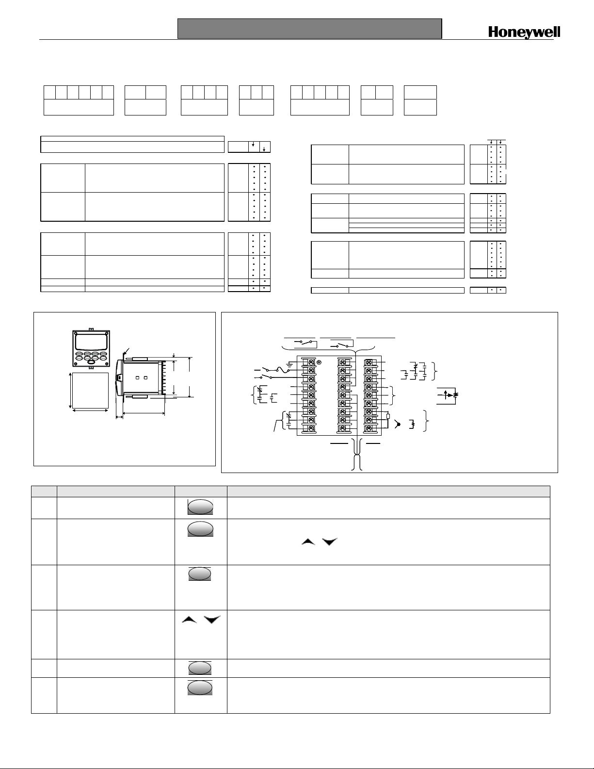
Step 1. Model Number Interpretation
Write your controller model number in the boxes. Then refer to Tables I, II, III,IV,V,VI and circle the corresponding options to identify your controller’s features. A dot
indicates the feature is available.
-
Key Number
Table I
II
KEY NUMBER - UDC3200 Single Loop Controller
Digital Controller for use with 90 to 264Vac Power DC3200
Digital Controller for use with 24Vac/dc Power DC3201
TABLE I - Specify Control Output and/or Alarms
Output #1
Output #2 and Alarm
#1 or Alarms 1 and 2
TABLE II - Communications and Software Selections
Communications
Software Selections
Reserved
Infrared interface
Current Output (4 to 20ma, 0 to 20 ma)
Electro Mechanical Relay (5 Amp Form C)
Solid State Relay (1 Amp)
Open Collector transistor output
Dual 2 Amp Relays (Both are Form A) (Heat/Cool Applications)
No Additional Outputs or Alarms
One Alarm Relay Only
E-M Relay (5 Amp Form C) Plus Alarm 1 (5 Amp Form C Relay)
Solid State Relay (1 Amp) Plus Alarm 1 (5 Amp Form C Relay)
Open Collector Plus Alarm 1 (5 Amp Form C Relay)
None
Auxiliary Output/Digital Inputs (1 Aux and 1 DI or 2 DI)
RS-485 Modbus Plus Auxiliary Output/Digital Inputs
10
Standard Functions, Includes Accutune
Math Option
Set Point Programming (1 Program, 12 Segments)
Set Point Programming Plus Math
No Selection
Infrared Interface Included (Can be used with a Pocket PC)
Description
Base-T Ethernet (Modbus RTU) Plus Auxiliary Output/Digital Inpu ts
Selection
0 _ _ _
1 _ _ _
2 _ _ _
3 _ _ _
_ 0 _ _
_ A _ _
_ B _ _
_ C _ _
_ _ 0 _
_ _ _ R
Step 2. Dimensions and mounting
Max. panel thickness
17,9
0,70
19,1
.75
113,1
4,45
mm
inches
92,0 + 0,8
-0,00
3,62 + 0,03
-0,00
Panel
Cutout
92,0 + 0,8
-0,00
3,62 + 0,03
-0,00
9,0
0,35
90,6
3,57
108,6
4,28
Step 3. Wiring
Output #2/
Output #2/
Alarm #2
Alarm #2
C _
E _
A _
T _
R _
_ 0
_ B
_ E
_ A
_ T
AC/DC
AC/DC
Line
Line
Voltage
Voltage
III
Availability
e
e
l
l
g
g
n
n
i
i
S
S
a
a
l
l
e
e
R
R
Earth Ground
Earth Ground
y
y
R
R
S
S
S
S
o
o
C
C
n
n
e
e
p
p
O
O
Alarm #1
Alarm #1
l
l
l
l
c
c
e
e
10 +
10 +
11 –
11 –
Neutral
Neutral
+
+
-
-
r
r
o
o
t
t
IV
TABLE III - Input 1 can be changed in t he field using external resistors Selection
Input 1
Input 2
TABLE IV - Options
Approvals
Future Options
TABLE V - Product Manuals
Manuals
Certificate
TABLE VI
No Selection
Digital Input #2Digital Input #1
Digital Input #2Digital Input #1
12 +
12 +
13 –
13 –
L1
Hot
Hot
L1
L2/N
L2/N
4
4
5
5
6
6
7
7
8
8
9
9
SHIELD 14
SHIELD 14
TC, RTD, mV, 0-5V, 1-5V
TC, RTD, mV, 0-5V, 1-5V, 0-20mA, 4-20mA
TC, RTD, mV, 0-5V, 1-5V, 0-20mA, 4-20mA, 0-10V
Carbon, Oxygen or Dewpoint (Requires Input 2) 1 6 0
None
TC, RTD, mV, 0-5V, 1-5V, 0-20mA, 4-20mA
TC, RTD, mV, 0-5V, 1-5V, 0-20mA, 4-20mA, 0-10V
Slidewire Input (Requires two Relay Outputs) _ 40
CE (Standard)
CE, UL and CSA
None
Tags
Linen Customer ID Tag - 3 lines w/22 characters/line
Stainless Steel Customer ID Tag - 3 lines w/22 characters/line
None
None
None
Product Information on CD - All Languages 0 _
English Manual E _
French Manual F _
German Manual G _
Italian Manual I _
Spanish Manual
None
Certificate of Conformance (F3391)
None 0 _
2ndCurrent Output
2ndCurrent Output
12 +
12 +
13 -
13 -
19
19
10
10
20
20
11
11
21
21
12
12
22
22
22
13
13
14
14
23
23
23
15
15
24
24
24
16
16
25
25
17
17
26
26
18
18
27
27
Ethernet
Ethernet
RXD - 15
RXD - 15
RXD + 16
RXD + 16
TXD - 17
TXD - 17
TXD + 18
TXD + 18
RS485
RS485
16 SHIELD
16 SHIELD
17 D+ (B)
17 D+ (B)
18 D - (A)
18 D - (A)
V
t
t
u
u
p
p
t
t
u
u
o
o
o
o
C
C
A
A
n
n
m
m
e
e
p
p
C
C
o
o
S
S
D
O
D
O
+
+
+
+
-
-
-
-
Input #2
Input #2
Same as Input #1
Same as Input #1
plus Slidewire input
plus Slidewire input
+
+
+
+
-+-
-+-
-
-
R
R
T
T
Li
Li
T
T
he
he
n
n
D
D
e
e
r
r
m
m
a
a
r
r
oc
oc
V
V
o
o
u
u
p
p
l
l
e
e
VI
Availability
DC 3200 3201
1 _ _
2 _ _
3 _ _
_ 00
_ 10
_ 20
0 _ _ _ _
1 _ _ _ _
_ 0 _ _ _
_ T _ _ _
_ S _ _ _
_ _ 0 _ _
_ _ _ 0 _
_ _ _ _ 0
S _
_ 0
_ C
y
y
a
a
l
l
r
r
e
e
o
o
t
t
y
y
R
R
c
c
a
a
y
y
l
l
e
e
e
e
l
l
t
t
l
l
a
a
e
e
l
l
a
a
t
R
t
R
e
e
S
S
R
R
e
e
l
l
l
l
d
d
g
g
i
i
a
a
l
l
n
n
u
u
i
i
S
S
D
D
2
2
Output #1
Output #1
1
1
Open
Open
Open
Wiper
Wiper
Wiper
Close
Close
Close
+
+
Input #1
Input #1
250
250
250
ohm
ohm
ohm
-
-
Li
Li
n
n
e
e
a
a
r
r
m
m
/
/
m
m
A
A
V
V
Step 4. Configuration Procedure
Step Operation Press Result
1 Enter Set Up Mode
2 Select any Set Up Group
SetupSetup
SetupSetup
Upper Display = SET
Lower Display = TUNING (This is the first Set Up Group title)
Sequentially displays the other Set Up group titles shown in the prompt hierarchy. (See 5.
Configuration Record Sheet for prompts.)
You can also use the
or keys to scan the Set Up groups in both directions. Stop at the Set
Up group title that describes the group of parameters you want to configure. Then proceed to the
next step.
3 Select a Function Parameter
FunctionFunctionFunction
Upper Display = the current value or selection for the first function prompt of the selected Set Up
group.
Lower Display = the first Function prompt within that Set Up group.
Sequentially displays the other function prompts of the Set Up group you have selected. Stop at the
function prompt that you want to change, then proceed to the next step.
4 Change the Value or Selection
or
Increments or decrements the value or selection that appears for the selected function prompt.
change the value or selection of a parameter while in Set Up mode but then decide not
to enter it, press the MAN/AUTO key once. This will recall the original configuration.
This “recall” procedure does not work for a Field Calibration process. Field Calibration is
5 Enter the Value or Selection
6 Exit Configuration
FunctionFunctionFunction
Lower
Lower
Lower
Display
Display
Display
a one-way operation.
Enters value or selection made into memory after another key is pressed.
Exits configuration mode and returns controller to the same state it was in immediately preceding
entry into the Set Up mode. It stores any changes you have made.
If you do not press any keys for 30 seconds, the controller times out and reverts to the mode and
display used prior to entry into Set Up mode.
If you
Page 1 of 4
Page 2
51-52-25-129
October 2004
Quick Start Guide for UDC3200 Universal Digital Controller
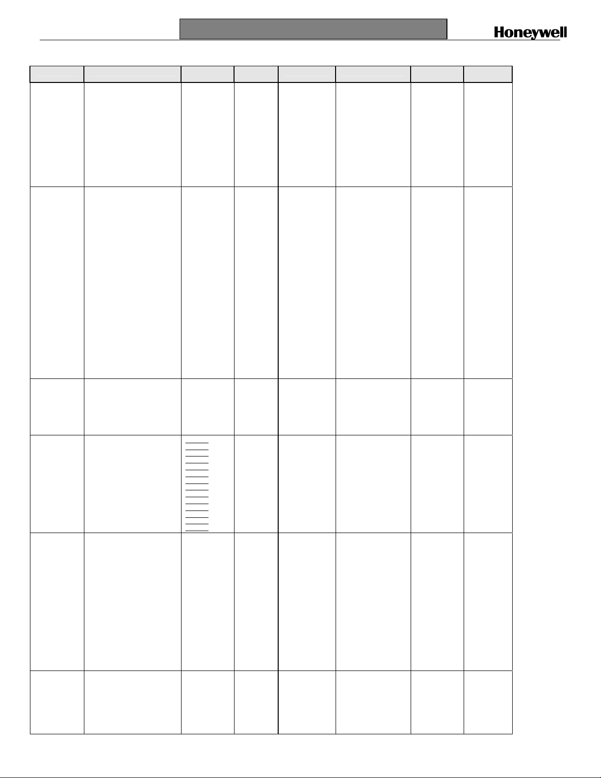
Step 5. Configuration Record Sheet
Enter the value or selection for each prompt on this sheet so you will have a record of how your controller was configured.
Group Prompt Function Prompt Value or
TUNING PROP BD or GAIN
SPRAMP SP RAMP
ACCUTUNE FUZZY
ALGOR CONT ALG
OUTALG OUT ALG
INPUT1 IN1 TYPE
GAINVALn
RATE MIN
RSET MIN or RSET RPM
MAN RSET
PROPBD2 or GAIN 2
RATE2MIN
RSET2MIN or RSET2RPM
CYC SEC or CYC SX3
CYC2 SEC or CYC2 SX3
SECURITY
LOCKOUT
AUTO MAN
SP SEL
RUN HOLD
TIME MIN
FINAL SP
HOTSTART
SP RATE
EU/HR UP
EU/HR DN
HOTSTART
SP PROG
ACCUTUNE
DUPLEX
AT ERROR
TIMER
PERIOD
START
L DISP
INP ALG1
MATH K
CALC HI
CALC LO
ALG1 INA
ALG1 INB
ALG1 INC
ALG1BIAS
PCT CO
RLYSTATE
RLY TYPE
MOTOR TI
CUR OUT
CO RANGE
LOW VAL
HIGH VAL
XMITTER1
IN1 HIgh
IN1 LOw
RATIO1
BIAS IN1
FILTER1
BURNOUT1
EMMISIV1
Selection
_______
READ ONLY
_______
_______
_______
_______
_______
_______
_______
_______
_______
_______
_______
_______
_______
_______
_______
_______
_______
_______
_______
_______
_______
_______
_______
_______
_______
Read Only
_______
_______
_______
_______
_______
_______
_______
_______
_______
_______
_______
_______
_______
_______
_______
_______
_______
_______
_______
_______
_______
_______
_______
_______
_______
_______
_______
_______
_______
_______
_______
Factory
Setting
1.000
----
0.00
1.0
0.0
1.00
0.00
1.00
20
20
0
CALIB
ENABLE
ENABLE
ENABLE
DISABLE
3
1000
DISABLE
DISABLE
0
0
DISABLE
DISABLE
DISABLE
DISABLE
MANUAL
NONE
PIDA
DIS
0:01
KEY
TREM
KEY
MIN
CURRENT
1 OF 2 ON
MECHAN
30
DISABLE
4-20Ma
0.0
100.0
0-10mV
LINEAR
1000
0
1.00
0.0
1
NONE
0.00
Group Prompt Function Prompt Value or
INPUT2
CONTRL PV SOURC
OPTION AUXOUT
COM ComSTATE
ALARMS A1S1 VA
DISPLY DECIMAL
IN2 TYPe
XMITTER2
IN2 HIgh
IN2 LOw
RATIO2
BIAS IN2
FILTER2
BURNOUT2
EMMISIV2
PID SETS
SW VALU E
LSP’S
RSP SRC
AUTO BIAS
SP TRACK
PWR MODE
PWR OUT
SP HiLIM
SP LoLIM
ACTION
OUT RATE
PCT/M UP
PCT/M DN
OUT HiLIM
OUT LoLIM
I Hi LIM
I Lo LIM
DROPOFF
DEADBAND
OUT HYST
FAILMODE
FAILSAFE
MAN AUTO
AUTO OUT
PBorGN
MINRPM
CO RANGE
LOW VAL
HIGH VAL
DIG INP 1
DIG1 COMB
DIG INP 2
DIG2 COMB
Com ADDR
IR ENABLE
BAUD
TX_DELAY
WSFLOAT
SHEDENAB
SHEDTIME
SHEDMODE
SHDSP
UNITS
CSP RATO
CSP_BIAS
LOOPBACK
A1S2 VA
A2S1 VA
A2S2 VA
A1S1TYPE
A1S2TYPE
A2S1TYPE
A2S2TYPE
A1S1 HL
A1S1 EV
A1S2 HL
A1S2 EV
A2S1HL
A2S1EV
A2S2HL
A2S2EV
ALHYST
ALM OUT1
BLOCK
DIAGNOST
TEMPUNIT
PWR FREQ
RATIO 2
LANGUAGE
Selection
_______
_______
_______
_______
_______
_______
_______
_______
_______
_______
_______
_______
_______
_______
_______
_______
_______
_______
_______
_______
_______
_______
_______
_______
_______
_______
_______
_______
_______
_______
_______
_______
_______
_______
_______
_______
_______
_______
_______
_______
_______
_______
_______
_______
_______
_______
_______
_______
_______
_______
_______
_______
_______
_______
_______
_______
_______
_______
_______
_______
_______
_______
_______
_______
_______
_______
_______
_______
_______
_______
_______
_______
_______
_______
_______
_______
_______
_______
_______
_______
_______
_______
_______
_______
Factory
Setting
1-10mV
LINEAR
1000
0
1.00
0
1
NONE
0.00
INPUT 1
1 ONLY
0.00
1 ONLY
NONE
DISABLE
NONE
MANUAL
LAST
1000
0
REVERSE
DISABLE
0
0
100
0.0
100.0
0.0
0
1.0
0.5
NO LATCH
0.0
---
--GAIN
MIN
DISABLE
4-20mA
0.O
100.0
NONE
DIS ABLE
NONE
DISABLE
DISABLE
3
ENABLE
19200
1
FP_B
DISABLE
30.0
LAST
TP LSP
PERCNT
1.0
0
DISABLE
90
10
95
5
NONE
NONE
NONE
NONE
HIGH
-LOW
-HIGH
-LOW
--
0.1
NO LAT
DISABLE
DISABLE
XXXX
NONE
60 HZ
DISABLE
ENGLISH
Page 2 of 4
Page 3

51-52-25-129
October 2004
(Ethernet addresses are accessible via PIE Tool)
Quick Start Guide for UDC3200 Universal Digital Controller
Step 6. Start Up Procedure for Operation
Step Operation Press Result
Man
Man
1 Select Manual
Mode
2 Adjust the Output
3 Enter the Local
Setpoint
4 Select Automatic
Mode
5 Tune the
Controller
Man
Auto
Auto
Auto
or
Lower
Lower
Lower
Display
Display
Display
or
Man
Man
Man
Auto
Auto
Auto
SetupSetup
Until “M” indicator is ON.
The controller is in manual mode.
To adjust the output value and ensure that the final control element is functioning correctly.
Upper Display = PV Value
Lower Display = OUT and the output value in %
Upper Display = PV Value
Lower Display = SP and the Local Setpoint Value
To adjust the local setpoint to the value at which you want the process variable maintained.
The local setpoint cannot be changed if the Setpoint Ramp function is running.
Until “A” indicator is ON.
The controller is in Automatic mode.
The controller will automatically adjust the output to maintain the process variable at setpoint.
Make sure the controller has been configured properly and all the values and selections have
been recorder on the Configuration Record Sheet.
Refer to Tuning Set Up group to ensure that the selections for PBor GAIN, RATE T, and I
MIN, or I RPM have been entered.
Use ACCUTUNE to tune the controller.
Procedure for Changing the Local Setpoints
Step Operation Press Result
Lower
Lower
1 Select the
Setpoint
Lower
Display
Display
Display
2 Change the
Value
3 Return to PV
Display
Lower
Lower
Lower
Display
Display
Display
Procedure for Switching Between Setpoints
You can switch Local and Remote setpoints or between two Local setpoints when configured.
ATTENTION The REMOTE SETPOINT value cannot be changed at the keyboard.
Step Operation Press Result
1 Select the
Setpoint
Select
Select
Select
Additional Operating Procedures
Until you see:
Upper Display = PV
Lower Display = SP or 2SP or 3SP (Value)
To change the Local Setpoint to the value at which you want the process maintained. The
or
display “blinks” if you attempt to enter setpoint values beyond the high and low limits..
To store immediately or will store after 30 seconds.
SP
SP
SP
To switch between the Three Local Setpoints and/or the Remote Setpoint.
ATTENTION “KEY ERROR” will appear in the
lower display, if:
• the remote setpoint or additional local setpoints are not configured as a setpoint source
• you attempt to change the setpoint while a setpoint ramp is enabled, or
• if you attempt to change the setpoint with the setpoint select function key disabled.
Page 3 of 4
Page 4

51-52-25-129
October 2004
Viewing the Operating Parameters
Press the LOWER DISPLAY key to scroll through the operating parameters listed.
The lower display will show only those parameters and their values that apply to your specific model.
Quick Start Guide for UDC2500 Limit Controller
Lower Display Key Parameter Prompts
Lower Display Description
OUT XX.X OUTPUT—Output value is shown in percent with one decimal point for all output types except
SP XXXX LOCAL SETPOINT #1—Also current setpoint when using SP Ramp.
2SP XXXX LOCAL SETPOINT #2
3SP XXXX LOCAL SETPOINT #3
RSP XXXX REMOTE SETPOINT
1IN XXXX INPUT 1—Used only with combinational input algorithms.
2IN XXXX INPUT 2
POS XX SLIDEWIRE POSITION—Used only with TPSC applications that use a slidewire input.
CSP XXXX COMPUTER SETPOINT—When SP is in override.
DEV XXXX DEVIATION—Maximum negative display is –999.9.
PIDSET X TUNING PARAMETER —where X is either 1 or 2.
ET HR.MN ELAPSED TIME—Time that has elapsed on the Timer in Hours.Minutes.
OTR HR.MN TIME REMAINING—Time remaining on the Timer in Hours.Minutes. The “O” is a rotating clock
RAMPXXXM SETPOINT RAMP TIME—Time remaining in the Setpoint Ramp in minutes.
SPN XXXX SETPOINT NOW—Current Setpoint when SP Rate is enabled. The SP XXXX display shows the
XXRAHR.MN RAMP SEGMENT NUMBER AND TIME REMAINING—Set Point Programming display. XX is
XXSKHR.MN SOAK SEGMENT NUMBER AND TIME REMAINING— Set Point Programming display. XX is
RECYC XX NUMBER OF SP PROGRAM RECYCLES REMAINING
To BEGIN RESET SP PROGRAM TO START OF FIRST SEGMENT
RERUN RESET SP PROGRAM TO START OF CURRENT SEGMENT
AUX XXXX AUXILIARY OUTPUT—Displayed only when output algorithm is not Current Duplex.
BIA XXXX BIAS—Displays the manual reset value for algorithm PD+MR.
TUNE OFF LIMIT CYCLE TUNING NOT RUNNING—Appears when Accutune is enabled but not operating.
DO FAST
Three Position Step Control (TPSC). For TPSC, when no slidewire is connected, this display is
an estimated motor position and is shown with no decimal point.
For Position Proportional Control, if the slidewire fails, then the instrument automatically
switches over to TPSC and the OUT display changes with it.
face.
“target” or final setpoint value.
the current segment number and HR.MN is the time remaining for this segment in
Hours.Minutes.
the current segment number and HR.MN is the time remaining for this segment in
Hours.Minutes.
Limit Cycle Tuning with the objective of producing quarter-damped tuning parameters. This
tuning may result in PV overshoot of the SP setting.
DO SLOW
Limit Cycle Tuning with the objective of producing damped or Dahlin tuning parameters,
depending upon the detected process deadtime. The tuning parameters calculated by this
selection are aimed at reducing PV overshoot of the SP setting.
Page 4 of 4
 Loading...