

Page 1

UDC2500
Universal Digital Controller
Product Manual
51-52-25-127
April 2007
Honeywell Process Solutions
Industrial Measurement and Control
Page 2

WARRANTY/REMEDY
Honeywell warrants goods of its manufacture as being free of defective materials and faulty
workmanship. Contact your local sales office for warranty information. If warranted goods are
returned to Honeywell during the period of coverage, Honeywell will repair or replace without charge
those items it finds defective. The foregoing is Buyer's sole remedy and is in lieu of all other
warranties, expressed or implied, including those of merchantability and fitness for a
particular purpose. Specifications may change without notice. The information we supply is
believed to be accurate and reliable as of this printing. However, we assume no responsibility for its
use.
While we provide application assistance personally, through our literature and the Honeywell web
site, it is up to the customer to determine the suitability of the product in the application.
Notices and Trademarks
Copyright 2007 by Honeywell
Revision 5 April 2007
Honeywell Process Solutions
Industrial Measurement and Control
512 Virginia Drive
Fort Washington, PA 19034
UDC2500 is a U.S. registered trademark of Honeywell
Other brand or product names are trademarks of their respective owners.
4/07 UDC2500 Universal Digital Controller Product Manual ii
Page 3

About This Document
Abstract
This document provides descriptions and procedures for the Installation, Configuration, Operation, and Troubleshooting of
your UDC2500 Controller.
Contacts
World Wide Web
The following lists Honeywell’s World Wide Web sites that will be o f interest to our customers.
Honeywell Organization WWW Address (URL)
Corporate http://www.honeywell.com
Industrial Measurement and Control http://www.honeywell.com/ps
Technical tips http://content.honeywell.com/ipc/faq
Telephone
Contact us by telephone at the numbers listed below.
United States and Canada Honeywell 1-800-423-9883 Tech. Support
Organization Phone Number
1-800-525-7439 Service
4/07 UDC2500 Universal Digital Controller Product Manual iii
Page 4
Introduction
Symbol Definitions
The following table lists those symbols used in this document to denote certain conditions.
Symbol Definition
This CAUTION symbol on the equipment refers the user to the Product Manual for
additional information. This symbol appears next to required information in the manual.
WARNING
PERSONAL INJURY: Risk of electrical shock. This symbol warns the user of a
potential shock hazard where HAZARDOUS LIVE voltages greater than 30 Vrms, 42.4
Vpeak, or 60 VDC may be accessible. Failure to comply with these instructions
could result in death or serious injury.
ATTENTION, Electrostatic Discharge (ESD) hazards. Observe precautions for
handling electrostatic sensitive devices
Protective Earth (PE) terminal. Provided for connection of the protective earth (green
or green/yellow) supply system conductor.
Functional earth terminal. Used for non-safety purposes such as noise immunity
improvement. NOTE: This connection shall be bonded to protective earth at the source
of supply in accordance with national local electrical code requirements.
Earth Ground. Functional earth connection. NOTE: This connection shall be bonded to
Protective earth at the source of supply in accordance with national and local electrical
code requirements.
Chassis Ground. Identifies a connection to the chassis or frame of the equipment shall
be bonded to Protective Earth at the source of supply in accordance with national and
local electrical code requirements.
4/07 UDC2500 Universal Digital Controller Product Manual iv
Page 5

Introduction
Contents
1 INTRODUCTION ...................................................................................................1
1.1 Overview.........................................................................................................................................1
1.2 Function of Displays and Keys.......................................................................................................3
1.3 Process Instrument Explorer Software............................................................................................4
1.4 CE Conformity (Europe).................................................................................................................5
2 INSTALLATION.....................................................................................................
2.1 Overview.........................................................................................................................................7
2.2 Condensed Specifications...............................................................................................................8
2.3 Model Number Interpretation .......................................................................................................12
2.4 Control and Alarm Relay Contact Information.............................................................................14
2.5 Mounting.......................................................................................................................................15
2.6 Wiring...........................................................................................................................................17
2.6.1 Electrical Considerations ...................................................................................................17
2.7 Wiring Diagrams...........................................................................................................................19
7
3 CONFIGURATION...............................................................................................32
3.1 Overview.......................................................................................................................................32
3.2 Configuration Prompt Hierarchy ..................................................................................................33
3.3 Configuration Procedure...............................................................................................................34
3.4 Tuning Set Up Group ....................................................................................................................35
3.5 SP Ramp Set Up Group ................................................................................................................39
3.6 Accutune Set Up Group................................................................................................................43
3.7 Algorithm Set Up Group...............................................................................................................46
3.8 Output Set Up Group....................................................................................................................51
3.9 Input 1 Set Up Group....................................................................................................................55
3.10 Input 2 Set Up Group ................................................................................................................59
3.11 Control Set Up Group ...............................................................................................................61
3.12 Options Group...........................................................................................................................67
3.13 Communications Group ............................................................................................................73
3.14 Alarms Set Up Group................................................................................................................76
3.15 Display Set Up Group ...............................................................................................................82
3.16 P.I.E. Tool Ethernet and Email Configuration Screens.............................................................84
3.17 Configuration Record Sheet......................................................................................................87
v UDC2500 Universal Digital Controller Product Manual 4/07
Page 6

Introduction
4 MONITORING AND OPERATING THE CONTROLLER.....................................89
4.1 Overview.......................................................................................................................................89
4.2 Operator Interface.........................................................................................................................90
4.3 Entering a Security Code ..............................................................................................................90
4.4 Lockout Feature............................................................................................................................ 91
4.5 Monitoring Your Controller..........................................................................................................93
4.5.1 Annunciators......................................................................................................................93
4.5.2 Viewing the operating parameters......................................................................................94
4.5.3 Diagnostic Messages..........................................................................................................95
4.6 Single Display Functionality.........................................................................................................97
4.7 Start Up Procedure for Operation .................................................................................................99
4.8 Control Modes ............................................................................................................................100
4.8.1 Mode Definitions .............................................................................................................100
4.8.2 What happens when you change modes...........................................................................101
4.9 Setpoints......................................................................................................................................101
4.10 Timer.......................................................................................................................................102
4.11 Accutune III.............................................................................................................................104
4.11.1 Tune for Simplex Outputs............................................................................................105
4.11.2 Tune for Duplex (Heat/Cool) .......................................................................................105
4.11.3 Using AUTOMATIC TUNE at start-up for Duplex (Heat/Cool).................................106
4.11.4 Using BLENDED TUNE at start-up for Duplex (Heat/Cool)......................................106
4.11.5 Using MANUAL TUNE at start-up for Duplex (Heat/Cool).......................................107
4.11.6 Error Codes...................................................................................................................109
4.12 Fuzzy Overshoot Suppression.................................................................................................110
4.13 Using Two Sets of Tuning Constants......................................................................................110
4.14 Alarm Setpoints.......................................................................................................................112
4.15 Three Position Step Control Algorithm...................................................................................113
4.16 Setting a Failsafe Output Value for Restart After a Power Loss.............................................114
4.17 Setting Failsafe Mode..............................................................................................................115
4.18 Setpoint Rate/Ramp/Program Overview.................................................................................115
4.19 Setpoint Ramp.........................................................................................................................116
4.20 Setpoint Rate ...........................................................................................................................117
4.21 Setpoint Ramp/Soak Programming.........................................................................................118
4.22 P.I.E. Tool Maintenance Screens ............................................................................................125
4.23 Configuring your Ethernet Connection...................................................................................131
5 INPUT CALIBRATION.......................................................................................136
5.1 Overview.....................................................................................................................................136
5.2 Minimum and Maximum Range Values..................................................................................... 137
5.3 Preliminary Information..............................................................................................................139
5.4 Input 1 Set Up Wiring .................................................................................................................140
4/07 UDC2500 Universal Digital Controller Product Manual vi
Page 7

Introduction
5.5 Input 1 Calibration Procedure.....................................................................................................144
5.6 Input 2 Set Up Wiring .................................................................................................................146
5.7 Input 2 Calibration Procedure.....................................................................................................147
5.8 Restore Input Factory Calibration...............................................................................................149
6 OUTPUT CALIBRATION...................................................................................151
6.1 Overview.....................................................................................................................................151
6.2 Current Output Calibration .........................................................................................................152
6.3 Auxiliary Output Calibration......................................................................................................154
6.4 Restore Output Factory Calibration Procedure...........................................................................156
7 TROUBLESHOOTING/SERVICE......................................................................158
7.1 Overview.....................................................................................................................................158
7.2 Troubleshooting Aids..................................................................................................................159
7.3 Power-up Tests............................................................................................................................161
7.4 Status Tests .................................................................................................................................161
7.5 Background Tests........................................................................................................................162
7.6 Controller Failure Symptoms......................................................................................................164
7.7 Troubleshooting Procedures .......................................................................................................165
7.8 Restoring Factory Configuration ................................................................................................174
7.9 Software Upgrades......................................................................................................................175
8 PARTS LIST......................................................................................................177
8.1 Exploded View............................................................................................................................177
8.2 Removing the chassis..................................................................................................................179
9 MODBUS RTU FUNCTION CODES..................................................................180
9.1 Overview.....................................................................................................................................180
9.2 General Information....................................................................................................................180
9.3 Function Code 20 (14h) - Read Configuration Reference Data..................................................182
9.3.1 Read Configuration Examples .........................................................................................184
9.4 Function Code 21 (15h) - Write Configuration Reference Data.................................................186
9.4.1 Write Configuration Examples ........................................................................................188
10 MODBUS READ, WRITE AND OVERRIDE PARAMETERS PLUS EXCEPTION
CODES........................................................................................................................189
10.1 Overview.................................................................................................................................189
10.2 Reading Control Data..............................................................................................................190
10.3 Read Software Options Status................................................................................................. 191
10.4 Miscellaneous Read Onlys......................................................................................................192
vii UDC2500 Universal Digital Controller Product Manual 4/07
Page 8

Introduction
10.4.1 Register Addresses for Read Onlys..............................................................................192
10.4.2 SetPoint Program Read Only Information....................................................................192
10.5 Setpoints..................................................................................................................................193
10.6 Using a Computer Setpoint (Overriding Controller Setpoint) ................................................194
10.7 Configuration Parameters........................................................................................................196
10.7.1 Tuning ..........................................................................................................................196
10.7.2 SP Ramp/Rate/Program................................................................................................198
10.7.3 Accutune.......................................................................................................................201
10.7.4 Algorithm .....................................................................................................................202
10.7.5 Output Algorithms........................................................................................................203
10.7.6 Input 1...........................................................................................................................204
10.7.7 Input 2...........................................................................................................................207
10.7.8 Control..........................................................................................................................209
10.7.9 Options .........................................................................................................................211
10.7.10 Communications...........................................................................................................213
10.7.11 Alarms ..........................................................................................................................214
10.7.12 Display..........................................................................................................................217
10.8 Modbus RTU Exception Codes............................................................................................... 218
11 ETHERNET TCP/IP...........................................................................................220
11.1 Overview.................................................................................................................................220
12 FURTHER INFORMATION................................................................................221
12.1 Modbus RTU Serial Communications ....................................................................................221
12.2 Modbus Messaging on TCP/IP................................................................................................221
12.3 How to Apply Digital Instrumentation in Severe Electrical Noise Environments..................221
13 INDEX ...............................................................................................................222
14 SALES AND SERVICE......................................................................................
226
4/07 UDC2500 Universal Digital Controller Product Manual viii
Page 9

Introduction
Tables
Table 2-1 Condensed Specifications _____________________________________________________ 8
Table 2-2 Control Relay Contact Information _____________________________________________ 14
Table 2-3 Alarm Relay Contact Information ______________________________________________ 14
Table 2-4 Mounting Procedure_________________________________________________________ 16
Table 2-5 Permissible Wiring Bundling__________________________________________________ 18
Table 2-6 Universal Output Functionality and Restrictions___________________________________ 20
Table 2-7 Terminals for connecting a UDC to a MDI Compliant Hub or Switch __________________ 30
Table 2-8 Terminals for connecting a UDC directly to a PC utilizing a straight-through cable________ 30
Table 3-1 Configuration Topics ________________________________________________________ 32
Table 3-2 Configuration Prompt Hierarchy _______________________________________________ 33
Table 3-3 Configuration Procedure _____________________________________________________ 34
Table 3-4 TUNING Group (Numeric Code 100) Function Prompts ____________________________ 35
Table 3-5 SPRAMP Group (Numeric Code 200) Function Prompts____________________________ 39
Table 3-6 ATUNE Group (Numeric Code 300) Function Prompts _____________________________ 44
Table 3-7 ALGOR Group (Numeric Code 400) Function Prompts_____________________________ 46
Table 3-8 OUTPUT Group (Numeric Code 500) Function Prompts____________________________ 51
Table 3-9 INPUT 1 Group (Numeric Code 600) Function Prompts ____________________________ 55
Table 3-10 INPUT2 Group (Numeric Code 700) Function Prompts____________________________ 59
Table 3-11 Table 3-12 CONTRL Group (Numeric Code 800) Function Prompts _________________ 61
Table 3-13 OPTION Group (Numeric Code 900) Function Prompts ___________________________ 67
Table 3-14 Communications Group (Numeric Code 1000) Function Prompts ____________________ 73
Table 3-15 ALARMS Group (Numeric Code 1100) Function Prompts _________________________ 76
Table 3-16 DISPLY Group (Numeric Code 1200) Function Prompts___________________________ 82
Table 4-1 Procedure to Enter a Security Code_____________________________________________ 91
Table 4-2 Annunciators ______________________________________________________________ 93
Table 4-3 Lower Display Key Parameter Prompts__________________________________________ 94
Table 4-4 Diagnostic Messages_________________________________________________________ 95
Table 4-5 Single Display Parameters ____________________________________________________ 98
Table 4-6 Procedure for Starting Up the Controller_________________________________________ 99
Table 4-7 Control Mode Definitions ___________________________________________________ 100
Table 4-8 Changing Control Modes (Dual Display Only)___________________________________ 101
Table 4-9 Procedure for Changing the Local Setpoints _____________________________________ 101
Table 4-10 Procedure for Switching Between Setpoints ____________________________________ 102
Table 4-11 Procedure for Starting “TUNE”______________________________________________ 105
Table 4-12 Procedure for Using AUTOMATIC TUNE at Start-up for Duplex Control ____________ 106
Table 4-13 Procedure for Using BLENDED TUNE at Start-up for Duplex Control_______________ 107
Table 4-14 Procedure for Using MANUAL TUNE for Heat side of Duplex Control ______________ 107
Table 4-15 Procedure for Using MANUAL TUNE for Cool side of Duplex Control______________ 108
Table 4-16 Procedure for Accessing Accutune Error Codes _________________________________ 109
Table 4-17 Accutune Error Codes _____________________________________________________ 109
Table 4-18 Set Up Procedure _________________________________________________________ 111
Table 4-19 Procedure for Switching PID SETS from the Keyboard ___________________________ 112
Table 4-20 Procedure for Displaying Alarm Setpoints _____________________________________ 112
Table 4-21 Procedure for Displaying 3Pstep Motor Position_________________________________ 113
Table 4-22 Procedure for Setting a Failsafe Value_________________________________________ 114
Table 4-23 Procedure for Setting a Failsafe Mode_________________________________________ 115
Table 4-24 Running A Setpoint Ramp__________________________________________________ 116
Table 4-25 Program Contents_________________________________________________________ 118
ix UDC2500 Universal Digital Controller Product Manual 4/07
Page 10

Introduction
Table 4-26 Run/Monitor Functions ____________________________________________________ 123
Table 5-1 Voltage, Milliamp and Resistance Equivalents for Input 1 Range Values ______________ 137
Table 5-2 Voltage and Milliamp Equivalents for Input 2 Range Values________________________ 139
Table 5-3 Equipment Needed_________________________________________________________ 139
Table 5-4 Set Up Wiring Procedure for Thermocouple Inputs Using an Ice Bath ________________ 140
Table 5-5 Set Up Wiring Procedure for Thermocouple Inputs using Thermocouple Source ________ 141
Table 5-6 Set Up Wiring Procedure for RTD Inputs _______________________________________ 141
Table 5-7 Set Up Wiring Procedure for Radiamatic, Millivolts, Volts or Thermocouple Differential Inputs
(Except 0-10 Volts) _____________________________________________________________
142
Table 5-8 Set Up Wiring Procedure for 0 to 10 Volts ______________________________________ 143
Table 5-9 Set Up Wiring Procedure for Milliampere Inputs _________________________________ 143
Table 5-10 Input 1 Calibration Procedure (Numeric Code 10000) ____________________________ 144
Table 5-11 Set Up Wiring Procedure for 0 to 20 mA or 4 to 20 mA Inputs – Input 2______________ 146
Table 5-12 Set Up Wiring Procedure for 0 to 2 Volts, 0 to 5 Volts, or 1 to 5 Volts – Input 2________ 147
Table 5-13 Input 2 Calibration Procedure (Numeric Code 20000) ____________________________ 148
Table 5-14 Restore Factory Calibration _________________________________________________ 149
Table 6-1 Set Up Wiring Procedure for Current Output ____________________________________ 152
Table 6-2 Current Output Calibration Procedure (Numeric Code 30000) ______________________ 153
Table 6-3 Set Up Wiring Procedure for Auxiliary Output___________________________________ 154
Table 6-4 Auxiliary Output Calibration Procedure (Numeric Code 50000) _____________________ 155
Table 6-5 Restore Factory Calibration Procedure _________________________________________ 156
Table 7-1 Procedure for Identifying the Software Version __________________________________ 160
Table 7-2 Procedure for Displaying the Status Test (Numeric Code 1200) Results _______________ 161
Table 7-3 Background Tests__________________________________________________________ 162
Table 7-4 Controller Failure Symptoms_________________________________________________ 164
Table 7-5 Troubleshooting Power Failure Symptoms ______________________________________ 166
Table 7-6 Troubleshooting Current Output Failure ________________________________________ 166
Table 7-7 Troubleshooting Three Position Step Control Output Failure________________________ 167
Table 7-8 Troubleshooting Time Proportional Output Failure _______________________________ 168
Table 7-9 Troubleshooting Current/Time or Time/Current Proportional Output Failure ___________ 169
Table 7-10 Troubleshooting Alarm Relay Output Failure ___________________________________ 170
Table 7-11 Troubleshooting a Keyboard Failure __________________________________________ 171
Table 7-12 Troubleshooting a RS-485 Communications Failure______________________________ 172
Table 7-13 Troubleshooting an Ethernet Communications Failure ____________________________ 173
Table 7-14 Troubleshooting Auxiliary Output Failure _____________________________________ 173
Table 7-15 Restoring Factory Configuration _____________________________________________ 174
Table 7-16 Software Upgrades________________________________________________________ 175
Table 8-1 Parts Identification_________________________________________________________ 178
Table 8-2 Parts Not Shown___________________________________________________________ 178
Table 8-3 Software Upgrades (see Section 7.9) ___________________________________________ 178
Table 9-1 Integer Parameter Type _____________________________________________________ 181
Table 9-2 Floating Point Parameter Type________________________________________________ 181
Table 9-3 Register Address Format for Function Code 20___________________________________ 183
Table 9-4 Register Address Format for Function Code 21___________________________________ 187
Table 10-1 Control Data Parameters ___________________________________________________ 191
Table 10-2 Option Status ____________________________________________________________ 191
Table 10-3 Miscellaneous Read Onlys__________________________________________________ 192
Table 10-4 SetPoint Program Read Only Information______________________________________ 192
Table 10-5 Setpoint Code Selections ___________________________________________________ 193
Table 10-6 Setpoint Associated Parameters______________________________________________ 193
4/07 UDC2500 Universal Digital Controller Product Manual x
Page 11

Introduction
Table 10-7 Computer Setpoint Selection ________________________________________________ 194
Table 10-8 Computer Setpoint Associated Parameters _____________________________________ 195
Table 10-9 Set-up Group – Tuning ____________________________________________________ 196
Table 10-10 Set-up Group – Setpoint Ramp/Rate _________________________________________ 198
Table 10-11 Set-up Group – Accutune__________________________________________________ 201
Table 10-12 Set-up Group – Algorithm _________________________________________________ 202
Table 10-13 Set-up Group – Output____________________________________________________ 203
Table 10-14 Set-up Group – Input 1____________________________________________________ 204
Table 10-15 Set-up Group – Input 2____________________________________________________ 207
Table 10-16 Set-up Group – Control ___________________________________________________ 209
Table 10-17 Set-up Group – Options ___________________________________________________ 211
Table 10-18 Set-up Group – Communications____________________________________________ 213
Table 10-19 Set-up Group – Alarms ___________________________________________________ 214
Table 10-20 Set-up Group – Display ___________________________________________________ 217
Table 10-21 Modbus RTU Data Layer Status Exception Codes ______________________________ 219
xi UDC2500 Universal Digital Controller Product Manual 4/07
Page 12

Introduction
Figures
Figure 1-1 UDC2500 Operator Interface (all display items shown) _____________________________ 2
Figure 1-2 Screen capture of Process Instrument Explorer running on a Pocket PC _________________ 4
Figure 1-3 Depiction of infrared communications ___________________________________________ 5
Figure 2-1 Model Number Interpretation_________________________________________________ 13
Figure 2-2 Mounting Dimensions (not to scale)____________________________________________ 15
Figure 2-3 Mounting Methods _________________________________________________________ 16
Figure 2-4 Composite Wiring Diagram __________________________________________________ 21
Figure 2-5 Mains Power Supply ________________________________________________________ 22
Figure 2-6 Input 1 Connections ________________________________________________________ 23
Figure 2-7 Input 2 Connections ________________________________________________________ 24
Figure 2-8 Electromechanical Relay Output ______________________________________________ 24
Figure 2-9 Solid State Relay Output ____________________________________________________ 25
Figure 2-10 Open Collector Output _____________________________________________________ 26
Figure 2-11 Dual Electromechanical Relay Option Output ___________________________________ 27
Figure 2-12 Current Output ___________________________________________________________ 27
Figure 2-13 Three Position Step Control Connections w/o Dual Relay Option____________________ 28
Figure 2-14 Three Position Step Control Connections with Dual Relay Option ___________________ 28
Figure 2-15 RS-422/485 Communications Option Connections _______________________________ 29
Figure 2-16 Ethernet Communications Option Connections __________________________________ 29
Figure 2-17 Auxiliary Output and Digital Inputs Option Connections __________________________ 30
Figure 2-18 Transmitter Power for 4-20 mA — 2 wire Transmitter Using Open Collector Alarm 2 Output31
Figure 2-19 Transmitter Power for 4-20 mA — 2 Wire Transmitter Using Auxiliary Output________ 31
Figure 3-1 Ethernet Configuration Screen ________________________________________________ 84
Figure 3-2 Email Configuration Screen __________________________________________________ 85
Figure 4-1 Operator Interface__________________________________________________________ 90
Figure 4-2 Functional Overview Block Diagram of the UDC2500 Controller ____________________ 96
Figure 4-3 Ramp/Soak Profile Example_________________________________________________ 121
Figure 4-4 Program Record Sheet _____________________________________________________ 122
Figure 4-5 Maintenance Data Menu____________________________________________________ 125
Figure 4-6 Loop Data Maintenance Screen ______________________________________________ 126
Figure 4-7 Alarm Details Maintenance Screen ___________________________________________ 127
Figure 4-8 Digital Input Details Screen _________________________________________________ 128
Figure 4-9 Status Data Maintenance Screen______________________________________________ 129
Figure 4-10 Ethernet Status Maintenance Screen__________________________________________ 130
Figure 4-11 IR Communications Address _______________________________________________ 131
Figure 4-12 Online Configuration _____________________________________________________ 132
Figure 4-13 Configuration Upload in Progress ___________________________________________ 132
Figure 4-14 Ethernet Communications Type Selection _____________________________________ 133
Figure 4-15 Ethernet Communications Address __________________________________________ 134
Figure 4-16 Configuration Upload in Progress ___________________________________________ 135
Figure 5-1 Input 1 and Input 2 Wiring Terminals _________________________________________ 139
Figure 5-2 Wiring Connections for Thermocouple Inputs Using an Ice Bath ____________________ 140
Figure 5-3 Wiring Connections for Thermocouple Inputs Using Thermocouple Source ___________ 141
Figure 5-4 Wiring Connections for RTD (Resistance Thermometer Device) ____________________ 141
Figure 5-5 Wiring Connections for Radiamatic, Thermocouple Differential, Millivolts or Volts (Except 0 to 10
Volts) ________________________________________________________________________
Figure 5-6 Wiring Connections for 0 to 10 Volts__________________________________________ 143
Figure 5-7 Wiring Connections for 0 to 20 mA or 4 to 20 mA Inputs__________________________ 143
142
4/07 UDC2500 Universal Digital Controller Product Manual xii
Page 13

Introduction
Figure 5-8 Wiring Connections for 0 to 20 mA or 4 to 20 mA Input – Input 2___________________ 146
Figure 5-9 Wiring Connections for 0 to 2 Volts, 0 to 5 Volts or 1 to 5 Volts Input – Input 2________ 147
Figure 6-1 Wiring Connections for Calibrating Current Output ______________________________ 152
Figure 6-2 Wiring Connections for Calibrating Auxiliary Output_____________________________ 154
Figure 8-1 UDC2500 Exploded View __________________________________________________ 177
Figure 10-1 Software Option Status Information__________________________________________ 191
xiii UDC2500 Universal Digital Controller Product Manual 4/07
Page 14

Page 15

1.1 Overview
Function
The UDC2500 is a microprocessor-based stand-alone controller. It combines a high
degree of functionality and operating simplicity in a 1/4 DIN size controller. This
instrument is an ideal controller for regulating temperature and other process variables in
numerous heating and cooling applications, as well as in metal working, food,
pharmaceuticals, semiconductor, testing and environmental work.
The UDC2500 monitors and controls temperatures and other variables in applications
such as environmental chambers, plastic processing machines, furnaces and ovens, and
packaging machinery.
Features
Introduction
1 Introduction
• 90 – 264 Vac or 24 Vac/dc Power Supply
• Input/Output Isolation
• Isolated Auxiliary Current Output / Digital Inputs
• Modbus® RS-485, Infrared, or Ethernet TCP/IP Communications
• Infrared interface
• Timer
• Accutune III Tuning with Fuzzy Logic Overshoot Suppression.
• 2nd Input (Remote Setpoint)
• Setpoint Ramp/Rate/Program
• Three Position Step Control
• Duplex (Heat/Cool)
Easy to Read Displays
The dedicated vacuum fluorescent displays with multi-language prompts make the
operator interface easy to read, understand and operate. Programmed sequences of
displays assure quick and accurate entry of all configurable parameters.
Easy to Operate
Simple keystrokes let you select input and range configuration, set the operating
parameters that meet you process control needs now, and change them later to meet new
ones.
4/07 UDC2500 Universal Digital Controller Product Manual 1
Page 16
Introduction
Mount Anywhere
This instrument is intended for industrial control applications. It must be panel mounted
with the wiring terminals enclosed within the panel. The instrument is environmentally
hardened and, when suitably enclosed, can be mounted anywhere in plant or factory, on
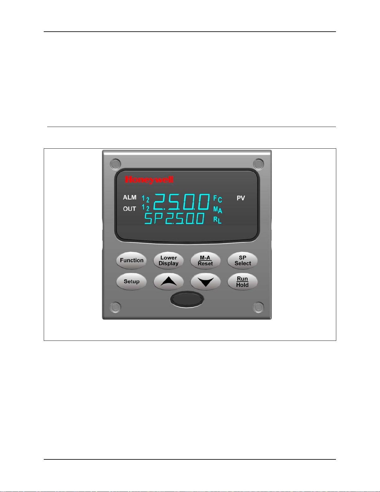
the wall, or even on the process machine itself. The front face is NEMA3 and IP55 rated
and can be easily changed to NEMA4X and IP66 for the most severe hose-down
applications. It withstands ambient temperatures up to 55°C (133°F) and resists the
effects of vibration and shock.
Figure 1-1 UDC2500 Operator Interface (all display items shown)
2 UDC2500 Universal Digital Controller Product Manual 4/07
Page 17
1.2 Function of Displays and Keys
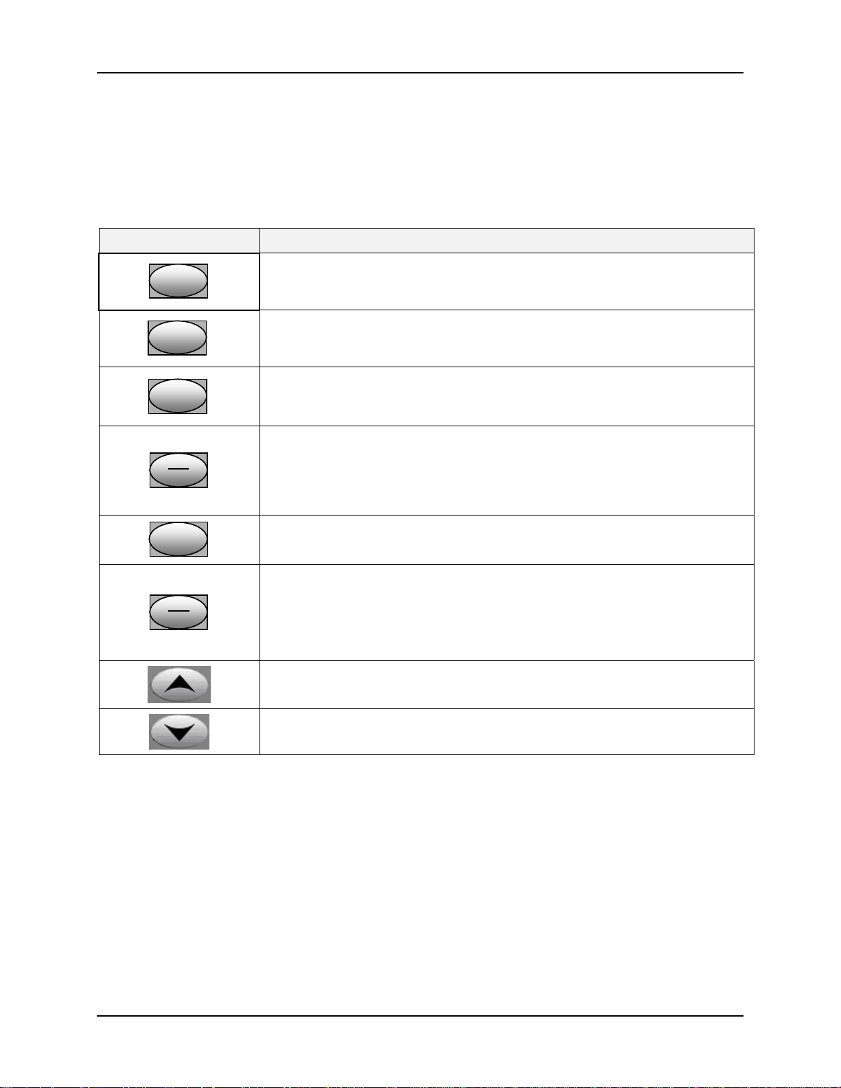
Table 1-1 shows each key on the operator interface and defines its function.
Table 1-1Function of Displays and Keys
Key Function
• Places the controller in the Configuration Set Up group select mode.
SetupSetup
FunctionFunctionFunction
Sequentially displays Set Up groups and allows the FUNCTION key to
display individual functions in each Set Up group.
• Used in conjunction with the SET UP key to select the individual functions of
a selected Configuration Set Up group.
• Used during field calibration procedure.
Introduction
Lower
Lower
Lower
Display
Display
Display
• Selects an operating parameter to be shown in the lower display. See
Section
4.5.2 for a list of the operating parameters and Section 4.5.3 for a list
of the diagnostic messages.
• Alternately selects:
M-A
M-A
M-A
Reset
Reset
Reset
AUTO Lower display automatically displays setpoint value in engineering
units.
MAN Lower display automatically indicates output in %.
RESET Only used on Limit Controllers to reset the Limit Relay.
SP
SP
SP
Select
Select
Select
• Setpoint Select Hold key down to cycle through configured setpoints.
• Alternate action switch initiates or holds the Setpoint Ramp or Setpoint
Run
Run
Run
Hold
Hold
Hold
Program.
• Acknowledges a latched alarm 1.
• Acknowledges Diagnostic Messages.
• Increases the selected parameter value.
• Decreases the selected parameter value.
Note 1: Value can be changed if in manual mode. For Three Position Step Control when a slidewire is
not used, the output value is the estimated motor position.
Note 2: Value can be changed via increment/decrement keys.
Note 3: The selected set can be changed via increment/decrement keys.
4/07 UDC2500 Universal Digital Controller Product Manual 3
Page 18
Introduction
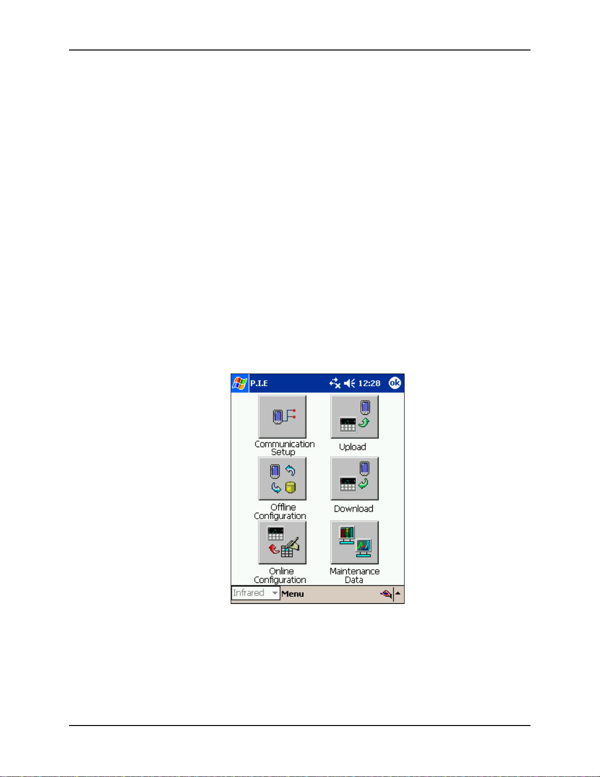
1.3 Process Instrument Explorer Software
Overview
Process Instrument Explorer lets you configure your instrument on a desktop/laptop or
Pocket PC. For details see Process Instrument Explorer manual #51-52-25-131.
Features
• Create configurations with intuitive software program running on either a Pocket
PC, a Desktop or a laptop computer. ·
• Create/edit configurations live, just connect software to controller via comm port.·
• Create/edit configurations offline and download to controller later via comm. port.·
• Port types available on every UDC2500:·
o Infrared
o RS 485
o Ethernet
• Same port types on UDC3200 and UDC3500 allow interconnectivity.
• This software is available in English, Spanish, Italian, German and French.
Figure 1-2 Screen capture of Process Instrument Explorer running on a Pocket
PC
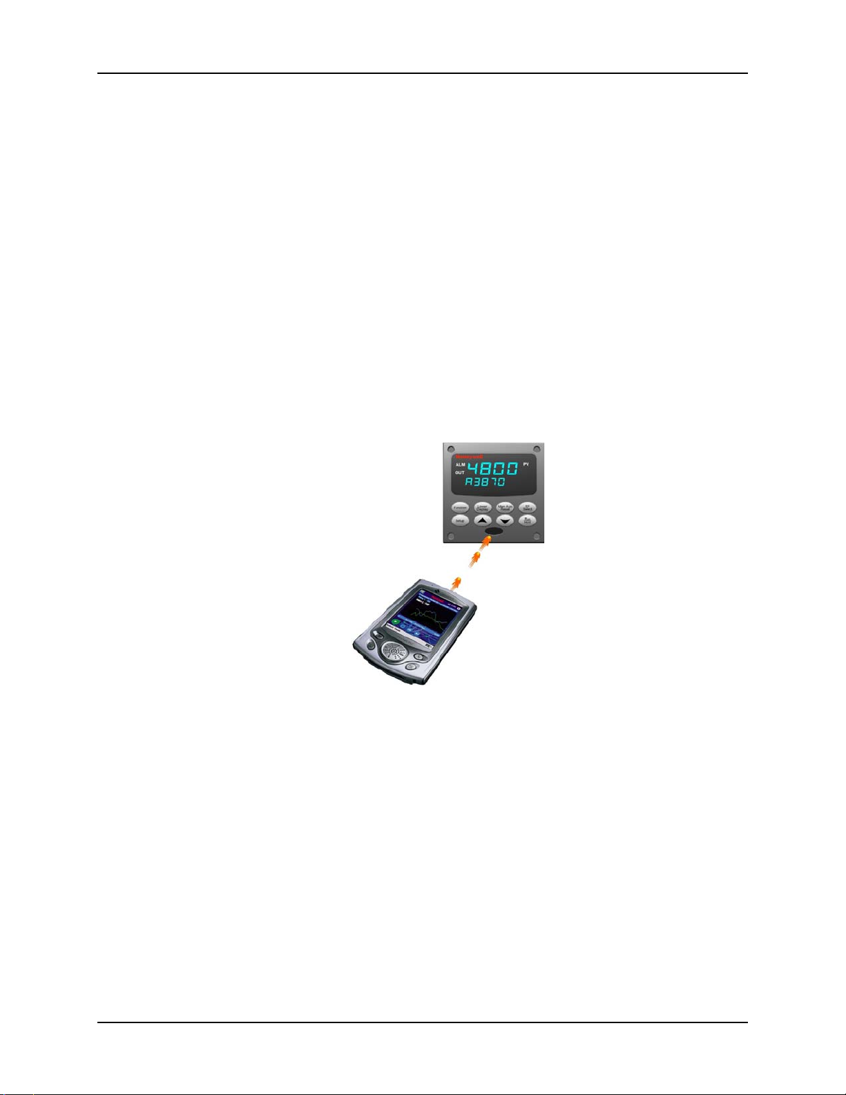
Infrared communications
The infrared connection provides a non-intrusive wireless connection with the instrument
and maintains NEMA4X AND IP66 integrity.
4 UDC2500 Universal Digital Controller Product Manual 4/07
Page 19
Introduction
No need to get access to the back of the controller to communicate with the instrument,
no need to take your screw driver to wire the communication cable, no wiring mistake
possible. You can now duplicate an instrument’s configuration, upload or download a
new configuration in a matter of seconds, just by pointing your Pocket PC in the direction
of the instrument.
It takes just a few seconds to upload a configuration from an instrument. You can then
save the configuration file onto your PC or pocket PC for review, modification or
archiving. Furthermore, this software also gives you important maintenance information
on the controller: instantly, get information on the current operating parameters, digital
inputs and alarm status, identify internal or analog input problems.
Question: What if I have several controllers on the same panel? How can I be sure I am
communicating with the correct one?
Answer: The infrared port of the controller is normally “off”. You activate the infrared
port by pressing any controller’s key. You can now communicate. After 4 minutes, the
port will be shut down again. Also, in the Communications Group “IR ENABLE” may be
disabled to prohibit IR communications.
Figure 1-3 Depiction of infrared communications
1.4 CE Conformity (Europe)
This product is in conformity with the protection requirements of the following European
Council Directives: 73/23/EEC, the Low Voltage Directive, and 89/336/EEC, the EMC
Directive. Conformity of this product with any other “CE Mark” Directive(s) shall not be
assumed.
Product Classification: Class I: Permanently connected, panel-mounted Industrial
Control Equipment with protective earthing (grounding) (EN61010-1).
Enclosure Rating: This controller must be panel-mounted with the rear terminals
enclosed within the panel. The front panel of the controller is rated at NEMA4X and IP66
when properly installed.
Installation Category (Overvoltage Category): Category II (EN61010-1)
4/07 UDC2500 Universal Digital Controller Product Manual 5
Page 20

Introduction
Pollution Degree: Pollution Degree 2: Normally non-conductive pollution with
occasional conductivity caused by condensation. (Ref. IEC 664-1)
EMC Classification: Group 1, Class A, ISM Equipment (EN61326, emissions), Industrial
Equipment (EN61326, immunity)
Method of EMC Assessment: Technical File (TF)
Declaration of Conformity: 51453655
Deviation from the installation conditions specified in this manual, and the special
conditions for CE conformity in Subsection 2.1, may invalidate this product’s conformity
with the Low Voltage and EMC Directives.
ATTENTION
The emission limits of EN61326 are designed to provide reasonable protection
against harmful interference when this equipment is operated in an industrial
environment. Operation of this equipment in a residential area may cause harmful
interference. This equipment generates, uses, and can radiate radio frequency
energy and may cause interference to radio and television reception when the
equipment is used closer than 30 meters (98 feet) to the antenna(e). In special
cases, when highly susceptible apparatus is used in close proximity, the user may
have to employ additional mitigating measures to further reduce the
electromagnetic emissions of this equipment.
WARNING
If this equipment is used in a manner not specified by the manufacturer, the
protection provided by the equipment may be impaired.
6 UDC2500 Universal Digital Controller Product Manual 4/07
Page 21
2.1 Overview
Introduction
Installation of the UDC2500 consists of mounting and wiring the controller according to
the instructions given in this section. Read the pre-installation information, check the
model number interpretation (Subsection 2.3), and become familiar with your model
selections, then proceed with installation.
What’s in this section?
The following topics are covered in this section.
2.1 Overview 7
Installation
2 Installation
TOPIC See Page
2.2 Condensed Specifications 8
2.3 Model Number Interpretation 12
2.4 Control and Alarm Relay Contact Information 14
2.5 Mounting 15
2.6 Wiring 17
2.7 Wiring Diagrams
Composite Wiring Diagram
AC Line Voltage
Input 1 Connections
Input 2 Connections
Relay Output
Electromechanical
Solid State
Open Collector
Dual Electromechanical Relay
Current Output Connections
Three Position Step Control Connections w/o Dual Relay
Three Position Step Control Connections with Dual Relay
RS-422/485 Communications Option
Ethernet Communications Option
Auxiliary Output and Digital Inputs Option
Transmitter Power using Open Collector Output
Transmitter Power using Auxiliary Output
19
21
22
23
24
24
25
26
27
27
28
28
29
29
30
31
31
4/07 UDC2500 Universal Digital Controller Product Manual 7
Page 22

Installation
Pre-installation Information
If the controller has not been removed from its shipping carton, inspect the carton for
damage then remove the controller.
• Inspect the unit for any obvious shipping damage and report any damage due to
transit to the carrier.
• Make sure a bag containing mounting hardware is included in the carton with the
controller.
• Check that the model number shown on the inside of the case agrees with what you
have ordered.
2.2 Condensed Specifications
Honeywell recommends that you review and adhere to the operating limits listed in Table
2-1 when you install your controller.
Table 2-1 Condensed Specifications
Analog Inputs
Analog Input Signal
Failure Operation
Stray Rejection Common Mode
Digital Inputs (Two)
(Optional)
Accuracy:
± 0.25% of full scale typical (± 1 digit for display)
Can be field calibrated to ± 0.05% of full scale typical
16-bit resolution typical
Sampling Rate: Both inputs are sampled six times per second
Temperature Stability: ± 0.01% of Full Scale span / ˚C change—typical
Input Impedance:
4-20 Milliampere Input: 250 ohms
0-10 Volt Input: 200K ohms
All Others: 10 megohms
Maximum Lead Wire Resistance:
Thermocouples: 50 ohms/leg
100 ohm, 200 ohm and 500 ohm RTD: 100 ohms/leg
100 ohm Low RTD: 10 ohms/leg
Burnout Selections: Upscale, Downscale, Failsafe or None
Thermocouple Health: Good, Failing, Failure Imminent or Failed
Failsafe Output Level: Configurable 0-100% of Output range
AC (50 or 60 Hz): 120 dB (with maximum source impedance of 100 ohms) or ± 1 LSB (least
significant bit) whichever is greater with line voltage applied.
DC: 120 dB (with maximum source impedance of 100 ohms) or a ±1 LSB whichever is
greater with 120 Vdc applied.
DC (to 1 KHz): 80 dB (with maximum source of impedance of 100 ohms) or ±1 LSB
whichever is greater with 50 Vac applied.
Normal Mode
AC (50 or 60 Hz): 60 dB (with 100 % span peak-to-peak maximum)
+30 Vdc source for external dry contacts or isolated solid state contacts. Digital Inputs are
isolated from line power, earth ground, analog inputs and all outputs except for the Second
Current Output.
The second Digital Input is mutually exclusive with the Second Current Output.
Specifications
8 UDC2500 Universal Digital Controller Product Manual 4/07
Page 23

Controller Output
Types
Alarm Outputs
(Optional)
Isolation (Functional)
Installation
Specifications
Electromechanical Relays (One or Two)
SPDT contacts. Both Normally Open and Normally Closed contacts are brought out to the
rear terminals. Internally socketed.
Resistive Load: 5 amps @ 120 Vac or 240 Vac or 30 Vdc
ϕ
Inductive Load (cos
Inductive Load (L/R = 7 msec): 3.5 amps @ 30 Vdc
Motor: 1/6 H.P.
Dual Electromechanical Relays
Two SPST contacts. One Normally Closed contact for each relay is brought out to the rear
terminals. Useful for Time Duplex or Three Position Step control applications, this option
takes the place of one of the above electromechanical relays, thus saving it for use as an
alarm. Units with this output option may have two additional relays (total of four relays) plus
the Second Current Output. Relays are internally socketed.
Resistive Load: 2 amps @ 120 Vac, 240 Vac or 30 Vdc
Inductive Load (cos
Inductive Load (L/R = 7 msec): 1 amp @ 30 Vdc
Solid State Relays (One or Two)
Zero-crossing type SPST solid state contacts consisting of a triac N.O. output. Internally
socketed.
Resistive Load: 1.0 amp @ 25°C and 120 or 240 Vac, 0.5 amp @ 55°C and 120 or 240 Vac
Inductive Load: 50 VA @ 120 Vac or 240 Vac
Minimum Load: 20 milliamps
Open Collector Outputs (One or Two)
Socketed assembly replacing a relay. Opto-isolated from all other circuits except current
output and not from each other. Internally powered @ 30 Vdc.
Note: Applying an external power supply to this output will damage the instrument.
Maximum Sink Current: 20 mA
Short-circuit current limit: 100 mA
Current Outputs (One or Two)
These outputs provide a 21 mA dc maximum into a negative or positive grounded load or into
a non-grounded load. Current outputs are isolated from each other, line power, earth ground
and all inputs. Outputs can be easily configured via the keyboard for either direct or reverse
action and for either 0 to 20 mA or 4 to 20 mA without field calibration.
The second current output can be used in an Auxiliary Output mode. This Auxiliary Output
can be configured to represent either Input, PV, Setpoint, Deviation, or Control output. The
range of an Auxiliary Output can be scaled per the range of the selected variable and can be
set anywhere between 0 to 21 mA. The Second Current Output is mutually exclusive with the
second Digital Input.
Resolution: 12 bits over 0 to 21 mA
Accuracy: 0.05% of full scale
Temperature Stability: 0.01% F.S./°C
Load Resistance: 0 to 1000 ohms
One SPDT Electromechanical relay. A second alarm is available if the second control relay
is not used for control purposes or when the Dual Relay Option is used.
Up to four setpoints are independently set as high or low alarm, two for each relay. Setpoint
can be on any Input, Process Variable, Deviation, Manual Mode, Failsafe, PV Rate, RSP
Mode, Communication Shed, or Output. A single adjustable hysteresis of 0.0 to 100.0% is
provided. The alarm can also be set as an ON or OFF event at the beginning of a Setpoint
ramp/soak segment.
Alarm Relay Contacts Rating: Resistive Load: 5 amps at 120 Vac or 240 Vac or 30 Vdc
Analog Inputs: are isolated from all other circuits at 850Vdc for 2 seconds, but not from each
other.
Analog Outputs: are isolated from all other circuits at 850Vdc for 2 seconds.
AC Power: is electrically isolated from all other inputs and outputs to withstand a HIPOT
potential of 1900Vdc for 2 seconds per Annex K of EN61010-1.
Relay Contacts: with a working voltage of 115/230 Vac, are isolated from each other and all
other circuits at 345Vdc for 2 seconds.
= 0.4): 3 amps @ 130 Vac or 250 Vac
ϕ
= 0.4): 1 amp @ 130 Vac or 250 Vac
4/07 UDC2500 Universal Digital Controller Product Manual 9
Page 24
Installation
RS422/485 Modbus
RTU
Communications
Interface (Optional)
Ethernet TCP/IP
Communications
Interface (Optional)
Infrared
Communications
(Optional)
Power Consumption
Power Inrush Current
Weight
Specifications
Baud Rate: 4800, 9600,19,200 or 38,400 baud selectable
Data Format: Floating point or integer
Length of Link:
2000 ft (600 m) max. with Belden 9271 Twinax Cable and 120 ohm termination resistors
4000 ft. (1200 m) max. with Belden 8227 Twinax Cable and 100 ohm termination resistors
Link Characteristics: Two-wire, multi-drop Modbus RTU protocol, 15 drops maximum or up
to 31 drops for shorter link length.
Type: 10Base-T
Length of Link: 330 ft. (100 m) maximum. Use Shielded twisted-pair, Category 5 (STP
CAT5) Ethernet cable.
Link Characteristics: Four-wire plus shield, single drop, five hops maximum
IP Address: IP Address is 10.0.0.2 as shipped from the Factory
Recommended network configuration: Use Switch rather than Hub in order to maximize
UDC Ethernet performance.
Configuration: Ethernet parameters are configured via the Process Instrument Explorer.
Email: The capability to send an Email is provided. This must be configured via the Process
Instrument Explorer.
Type: Serial Infrared (SIR)
Length of Link: 3 ft. (1 m) maximum for IrDA 1.0 compliant devices
Baud Rate: 19,200 or 38,400 baud selectable
20 VA maximum (90 to 264 Vac)
15 VA maximum (24 Vac/dc)
10A maximum for 4 ms (under operating conditions), reducing to a maximum of 225 mA (90
to 264 Vac operation) or 750 mA (24 Vac/dc operation) after one second.
CAUTION
power is supplied. Otherwise, the instruments may not start up normally due to voltage drop
from the inrush current.
3 lbs. (1.3 kg)
When applying power to more than one instrument, make sure that sufficient
10 UDC2500 Universal Digital Controller Product Manual 4/07
Page 25

Environmental and Operating Conditions
Installation
Parameter Reference Rated Operative
Limits
Ambient Temperature
Relative Humidity
Vibration
Frequency (Hz)
Acceleration (g)
Mechanical Shock
Acceleration (g)
Duration (ms))
Line Voltage (Vdc)
Line Voltage (Vac)
90 to 240 Vac
24 Vac
Frequency (Hz)
(For Vac)
* The maximum moisture rating only applies up to 40 °C (104 °F). For higher temperatures, the RH specification is
derated to maintain constant moisture content.
25 ± 3 °C
77 ± 5 °F
10 to 55* 10 to 90* 5 to 90* 5 to 95*
0
0
0
0
+24 ± 1 22 to 27 20 to 27 - -
120 ± 1
240 ± 2
24 ± 1
50 ± 0.2
60 ± 0.2
15 to 55 °C
58 to 131 °F
0 to 70
0.4
1
30
90 to 240
20 to 27
49 to 51
59 to 61
0 to 55 °C
32 to 131 °F
0 to 200
0.6
5
30
90 to 264
20 to 27
48 to 52
58 to 62
Transportation and
Storage
–40 to 66 °C
–40 to 151 °F
0 to 200
0.5
20
30
- -
- -
- -
- -
- -
4/07 UDC2500 Universal Digital Controller Product Manual 11
Page 26
Installation
_
r
_
_
_
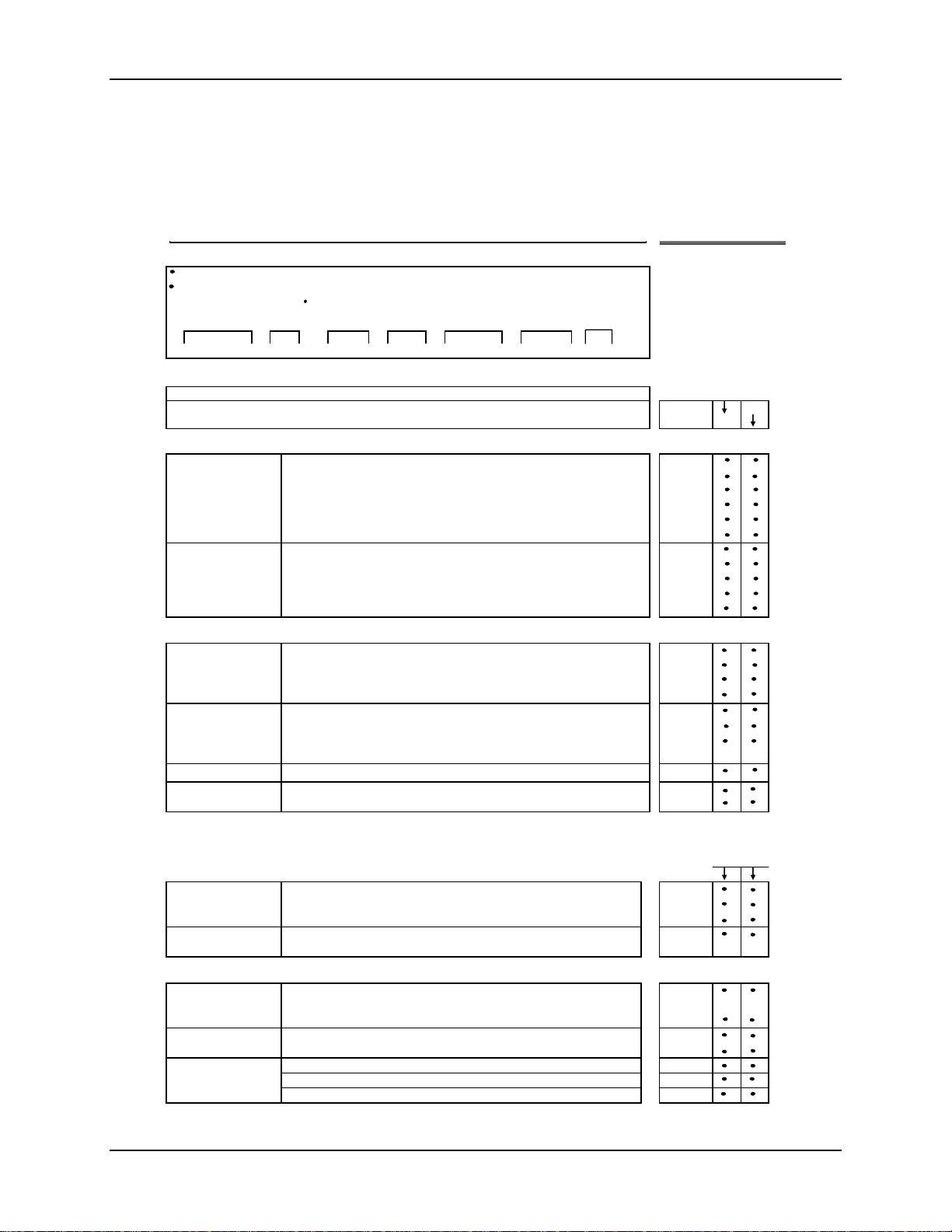
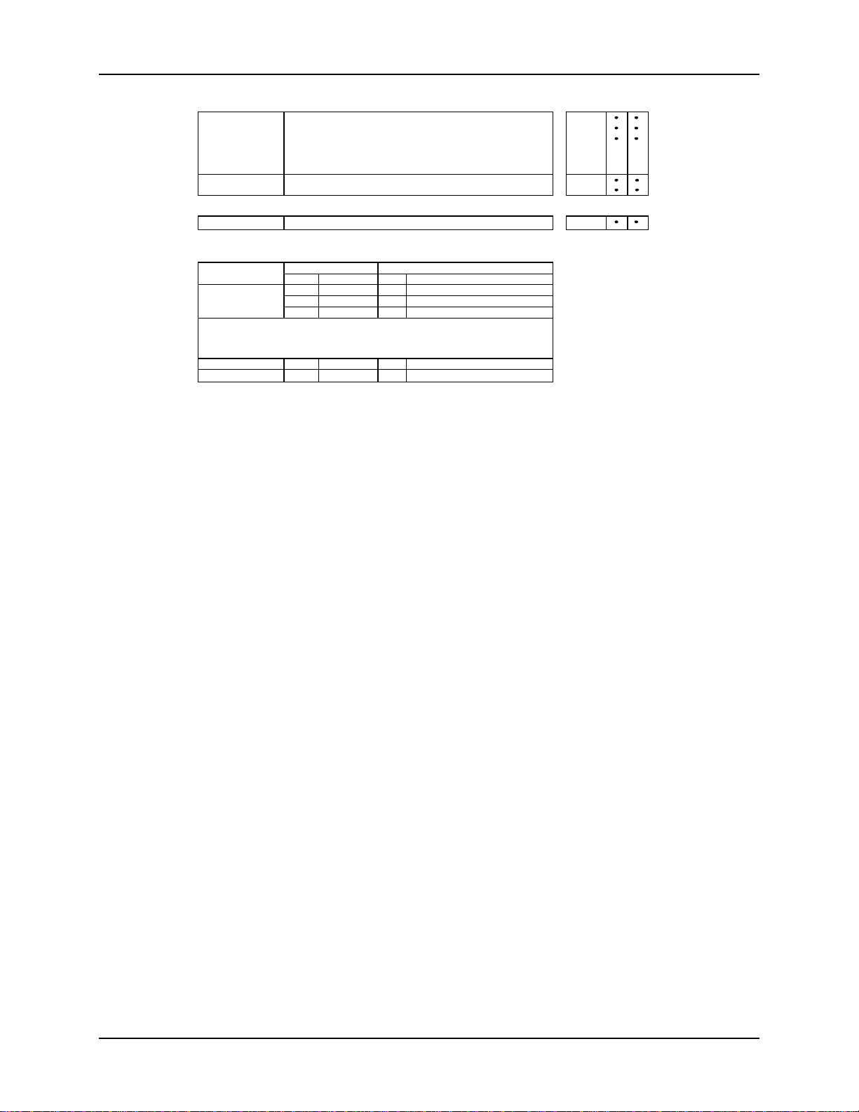
2.3 Model Number Interpretation
Introduction
Write your controller’s model number in the spaces provided below and circle the corresponding
items in each table. This information will also be useful when you wire your controller.
Instructions
Select the desired key number. The arrow to the right marks the selection available.
Make the desired selections from Tables I through VI using the column below the
proper arrow. A dot ( ) denotes availability.
Key Number
I
- - - - _ _ _ _ _-
_
_ _ _ __ _ _ _ _
IIIII IV VI
_ _ _
KEY NUMBER - UDC2500 Single Loop Controlle
Digital Controller for use with 90 to 264Vac Power DC2500
Digital Controller for use with 24Vac/dc Power DC2501
Description
TABLE I - Specify Control Output and/or Alarms
None (Can be used as an indicator only)
Current Output (4 to 20ma, 0 to 20 ma)
Output #1
Output #2 and Alarm
#1 or Alarms 1 and 2
Electro Mechanical Relay (5 Amp Form C)
Solid State Relay (1 Amp)
Open Collector transistor output
Dual 2 Amp Relays (Both are Form A) (Heat/Cool Applications)
No Additional Outputs or Alarms
One Alarm Relay Only
E-M Relay (5 Amp Form C) Plus Alarm 1 (5 Amp Form C Relay)
Solid State Relay (1 Amp) Plus Alarm 1 (5 Amp Form C Relay)
Open Collector Plus Alarm 1 (5 Amp Form C Relay)
TABLE II - Communications and Software Selections
None
Communications
Software Selections
Reserved
Infrared interface
Auxiliary Output/Digital Inputs (1 Aux and 1 DI or 2 DI)
RS-485 Modbus Plus Auxiliary Output/Digital Inputs
Base-T Ethernet (Modbus RTU) Plus Auxiliary Output/Digital Inputs 3 _ _ _
10
Standard Functions, Single Display
Dual Display with Auto/Manual
Set Point Programming (12 Segments) Dual Display, Auto/Manual
Limit Controller
No Selection
None
Infrared Interface Included (Can be used with a Pocket PC)
TABLE III - Input 1 can be changed in the field using external resistors
Input 1
Input 2
TC, RTD, mV, 0-5V, 1-5V
TC, RTD, mV, 0-5V, 1-5V, 0-20mA, 4-20mA
TC, RTD, mV, 0-5V, 1-5V, 0-20mA, 4-20mA, 0-10V
None
0-5V, 1-5V, 0-20mA, 4-20mA
TABLE IV - Options
Approvals
Tags
Future Options
CE, UL and CSA (Standard)
CE, UL, CSA and FM
CE Only
None
Stainless Steel Customer ID Tag - 3 lines w/22 characters/line
None
None
None
V
_
Selection
_ 0 _ _
_ A _ _
_ B _ _
_ _ _ R
0 _
C _
E _
A _
T _
R _
_ 0
_ B
_ E
_ A
_ T
0 _ _ _
1 _ _ _
2 _ _ _
_ L _ _
_ _ 0 _
_ _ _ 0
Availability
aa
Availability
DC 2500 2501
Selection
1 _ _
2 _ _
3 _ _
_ 00
_ 10
0 _ _ _ _
1 _ _ _ _
2 _ _ _ _
_ 0 _ _ _
_ T _ _ _
_ _ 0 _ _
_ _ _ 0 _
_ _ _ _ 0
bb
cc
12 UDC2500 Universal Digital Controller Product Manual 4/07
Page 27
Installation
TABLE V - Product Manuals
Manuals
Certificate
TABLE VI
No Selection
RESTRICTIONS
Restriction Letters
a
Limit Controller Restrictions/Comments:
1. FM approved units with communications are limited to read only.
2. UL listed for regulatory use only.
b
c
Product Information on CD - English 0 _
English (Hard Copy) Manual (51-52-25-127) E _
French (Hard Copy) Manual (51-52-25-127-FR) F _
German (Hard Copy) Manual (51-52-25-127-DE) G _
Italian (Hard Copy) Manual (51-52-25-127-IT) I _
Spanish (Hard Copy) Manual (51-52-25-127-SP)
None
Certificate of Conformance (F3391)
None 0
II
I
Not Available With
_ L _ _
C _, R _
Available Only With
Table
Selection
I
I
I
_ L _ _
II
Table Selection
E _
A _
T _
S _
_ 0
_ C
Figure 2-1 Model Number Interpretation
4/07 UDC2500 Universal Digital Controller Product Manual 13
Page 28
Installation
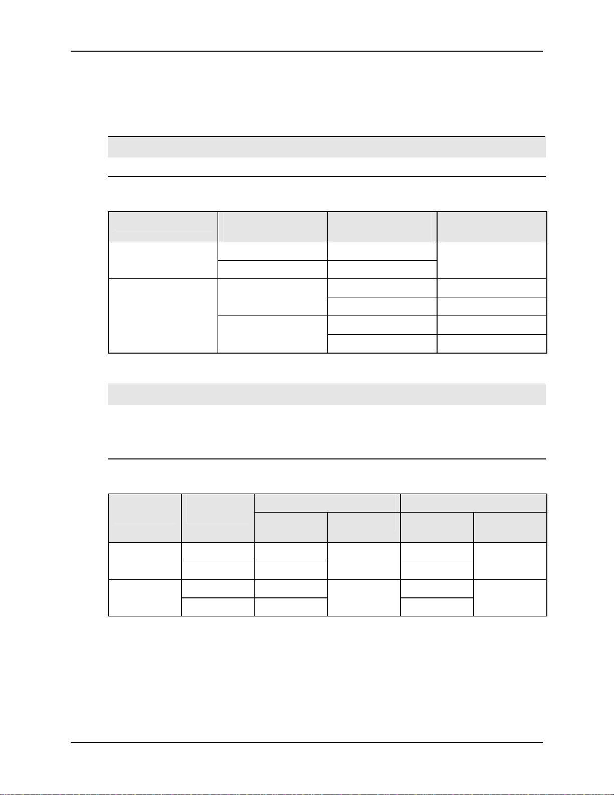
2.4 Control and Alarm Relay Contact Information
Control Relays
ATTENTION
Control relays operate in the standard control mode (that is, energized when output state is on).
Table 2-2 Control Relay Contact Information
Unit Power Control Relay
Alarm Relays
ATTENTION
Alarm relays are designed to operate in a failsafe mode (that is, de-energized during alarm
sate). This results in alarm actuation when power is OFF or when initially applied, until the unit
completes self diagnostics. If power is lost to the unit, the alarms will de-energize and thus the
alarm contacts will close.
Power
Off
On
Control Relay
Wiring
N.O. Open
N.C. Closed
N.O.
N.C.
Contact
Open
Closed
Closed
Open
Table 2-3 Alarm Relay Contact Information
Alarm Relay
Wiring
Variable NOT in Alarm State Variable in Alarm State Unit
Relay
Contact
Indicators Relay
Output #1 or #2
Indicator Status
Off
Off
On
Off
On
Indicators
Contact
Off
On
14 UDC2500 Universal Digital Controller Product Manual 4/07
N.O. Open Open
N.C. Closed
N.O. Closed Open
N.C. Open
Off
Closed
Off
Closed
Off
On
Page 29

2.5 Mounting
Physical Considerations
The controller can be mounted on either a vertical or tilted panel using the mounting kit
supplied. Adequate access space must be available at the back of the panel for installation
and servicing activities.
• Overall dimensions and panel cutout requirements for mounting the controller are
shown in Figure 2-2.
• The controller’s mounting enclosure must be grounded according to CSA standard
C22.2 No. 0.4 or Factory Mutual Class No. 3820 paragraph 6.1.5.
• The front panel is moisture rated NEMA3 and IP55 rated and can be easily upgraded
to NEMA4X and IP66.
Overall Dimensions
mm
inches
Max. panel thickness
19,1
.75
9,0
0,35
Installation
92,0 + 0,8
-0,00
3,62 + 0,03
-0,00
Panel
Cutout
92,0 + 0,8
-0,00
3,62 + 0,03
-0,00
Figure 2-2 Mounting Dimensions (not to scale)
17,9
0,70
113,1
4,45
90,6
3,57
108,6
4,28
4/07 UDC2500 Universal Digital Controller Product Manual 15
Page 30
Installation
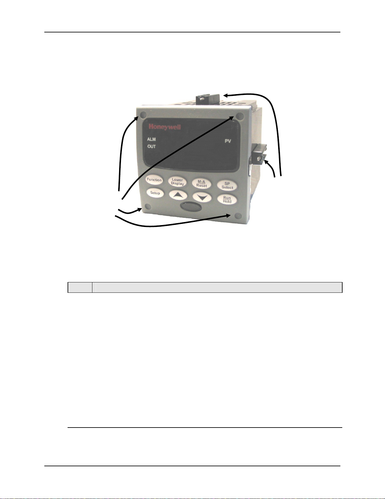
Mounting Method
Before mounting the controller, refer to the nameplate on the outside of the case and
make a note of the model number. It will help later when selecting the proper wiring
configuration.
Attach screws and
washers here for
water protection
Mounting clips
Mounting Procedure
Step Action
Mark and cut out the controller hole in the panel according to the dimension
1
information in
Orient the case properly and slide it through the panel hole from the front.
2
Remove the mounting kit from the shipping container and install the kit as follows:
3
• For normal installation two mounting clips are required. Insert the prongs of the
clips into the two holes in the top and bottom center of the case (
• For water-protected installation four mounting clips are required. There are two
options of where to install the mounting clips: 1) Insert the prongs of the clips into
the two holes on the left and right side of the top and bottom of the case or 2) on
the center on each of the four sides (
• Tighten screws to 2 lb-inch (22 N•cm) to secure the case against the panel.
CAUTION: Over tightening will cause distortion and the unit may not seal properly.
For water-protected installation, install four screws with washers into the four recessed
4
areas in the corners of the front bezel (
through the center piercing the elastomeric material and then tighten screws to 5 lb-in
(56 N•cm).
Figure 2-3 Mounting Methods
Table 2-4 Mounting Procedure
Figure 2-2.
Figure 2-3).
Figure 2-3).
Figure 2-3). Push the point of the screw
16 UDC2500 Universal Digital Controller Product Manual 4/07
Page 31

2.6 Wiring
2.6.1 Electrical Considerations Line voltage wiring
This controller is considered “rack and panel mounted equipment” per EN61010-1,
Safety Requirements for Electrical Equipment for Measurement, Control, and Laboratory
Use, Part 1: General Requirements. Conformity with 72/23/EEC, the Low Voltage
Directive requires the user to provide adequate protection against a shock hazard. The
user shall install this controller in an enclosure that limits OPERATOR access to the rear
terminals.
Mains Power Supply
This equipment is suitable for connection to 90 to 264 Vac or to 24 Vac/dc 50/60 Hz,
power supply mains. It is the user’s responsibility to provide a switch and non-time delay
(North America), quick-acting, high breaking capacity, Type F (Europe), 1/2A, 250V
fuse(s), or circuit-breaker for 90-264 Vac applications; or 1 A, 125 V fuse or circuit
breaker for 24 Vac/dc applications, as part of the installation. The switch or circuitbreaker shall be located in close proximity to the controller, within easy reach of the
OPERATOR. The switch or circuit-breaker shall be marked as the disconnecting device
for the controller.
CAUTION
When applying power to multiple instruments, make certain that sufficient current is
supplied. Otherwise, the instruments may not start up normally due to the voltage drop
caused by the in-rush current.
Applying 90-264 Vac to an instrument rated for 24 Vac/dc will severely
damage the instrument and is a fire and smoke hazard.
Installation
Controller Grounding
PROTECTIVE BONDING (grounding) of this controller and the enclosure in which it is
installed shall be in accordance with National and Local electrical codes. To minimize
electrical noise and transients that may adversely affect the system, supplementary
2
bonding of the controller enclosure to a local ground, using a No. 12 (4 mm
) copper
conductor, is recommended.
Control/Alarm Circuit Wiring
The insulation of wires connected to the Control/Alarm terminals shall be rated for the
highest voltage involved. Extra Low Voltage (ELV) wiring (input, current output, and
low voltage Control/Alarm circuits) shall be separated from HAZARDOUS LIVE (>30
Vac, 42.4 Vpeak, or 60 Vdc) wiring per Permissible Wiring Bundling, Table 2-5.
Electrical Noise Precautions
Electrical noise is composed of unabated electrical signals which produce undesirable
effects in measurements and control circuits.
4/07 UDC2500 Universal Digital Controller Product Manual 17
Page 32

Installation
Digital equipment is especially sensitive to the effects of electrical noise. Your controller
has built-in circuits to reduce the effect of electrical noise from various sources. If there
is a need to further reduce these effects:
• Separate External Wiring—Separate connecting wires into bundles
(See Permissible Wiring Bundling - Table 2-5) and route the individual bundles
through separate conduit metal trays.
Use Suppression Devices—For additional noise protection, you may want to add
suppression devices at the external source. Appropriate suppression devices are
commercially available.
ATTENTION
For additional noise information, refer to document number 51-52-05-01, How to Apply Digital
Instrumentation in Severe Electrical Noise Environments.
Permissible Wiring Bundling
Table 2-5 Permissible Wiring Bundling
Bundle No. Wire Functions
1
2 Analog signal wire, such as:
3
• Line power wiring
• Earth ground wiring
• Line voltage control relay output wiring
• Line voltage alarm wiring
• Input signal wire (thermocouple, 4 to 20 mA, etc.)
• 4-20 mA output signal wiring
Digital input signals
• Low voltage alarm relay output wiring
• Low voltage wiring to solid state type control circuits
• Low voltage wiring to open collector type control circuits
18 UDC2500 Universal Digital Controller Product Manual 4/07
Page 33

2.7 Wiring Diagrams
Identify Your Wiring Requirements
To determine the appropriate diagrams for wiring your controller, refer to the model
number interpretation in this section. The model number of the controller is on the
outside of the case.
Universal Output Functionality and Restrictions
Instruments with multiple outputs can be configured to perform a variety of output types
and alarms. For example, an instrument with one current output and two relays can be
configured to provide any one of the following:
1) Current Simplex with two alarm relays
2) Current Duplex 100% with two alarm relays
3) Time Simplex with one alarm relay
4) Time Duplex with no alarm relays
5) Three Position Step Control with no alarm relays
These selections may all be made via the keyboard and by wiring to the appropriate
output terminals; there are no internal jumpers or switches to change. This flexibility
allows a customer to stock a single instrument which is able to handle a variety of
applications.
Table 2-6 shows what control types and alarms are available based upon the installed
outputs. In this table, when Duplex Control and Reverse Action are configured:
Installation
Output 1 is HEAT and Output 2 is COOL.
In Table 2-6 when Three Position Step Control is configured:
Output 1 is OPEN and Output 2 is CLOSE.
Table 2-6 the Output 1/2 option Single Relay can be any of the following selections:
In
Electro-Mechanical Relay, Solid-State Relay or Open Collector Output.
4/07 UDC2500 Universal Digital Controller Product Manual 19
Page 34

Installation
Type
Time Simplex
Time Duplex or
TPSC
Current Simplex
Current Dup. 100%
Current = COOL
and HEAT
Current Duplex
50%
Current = HEAT
Aux Out = COOL
Current/Time
Current = COOL
Time = HEAT
Time/Current
Time = COOL
Current = HEAT
Table 2-6 Universal Output Functionality and Restrictions
Output 1/2
Option
Single Relay Output 1 Alarm 2 Alarm 1 Not Needed
Current Output INU Output 1 Alarm 1 Not Needed
Dual Relay Output 1 Alarm 2 Alarm 1 Not Needed
Single Relay Output 1 Output 2 Alarm 1 Not Needed
Current Output INU Output 2 Output 1 Not Needed
Dual Relay Outputs 1 and
Single Relay INU Alarm 2 Alarm 1 Output 1
Current Output Output 1 Alarm 2 Alarm 1 Not Needed
Dual Relay INU Alarm 2 Alarm 1 Output 1
Single Relay INU Alarm 2 Alarm 1 Outputs 1 and 2
Current Output Outputs 1 and
Dual Relay INU Alarm 2 Alarm 1 Outputs 1 and 2
Single Relay N/A N/A N/A N/A
Current Output Output 1 Alarm 2 Alarm 1 Output 2
Dual Relay N/A N/A N/A N/A
Single Relay * Output 1 Output 2 Alarm 1 Output 2
Current Output Output 2 Output 2 Alarm 1 Not Needed
Dual Relay * Outputs 1 & 2 Alarm 2 Alarm 1 Output 2
Single Relay * Output 1 Output 2 Alarm 1 Output 1
Current Output Output 1 Output 2 Alarm 1 Not Needed
Dual Relay * Outputs 1 & 2 Alarm 2 Alarm 1 Output 1
Function of
Output 1/2
2
2
Output #3 Output #4 Auxiliary Output
Alarm 2 Alarm 1 Not Needed
Alarm 2 Alarm 1 Not Needed
Function of Other Outputs Output Algorithm
TPSC = Three Position Step Control
N/A = Not Available – This output algorithm type cannot be performed with this Output 1/2
option.
INU = Installed, Not Used – The installed Output 1/2 option is not used for the configured
output algorithm type.
Not Needed = Auxiliary Output is Not Needed to provide the desired output algorithm and can
be used for another purpose. With the proper configuration, Auxiliary Output
could also be used as a substitute for the Current Output
* To obtain this output algorithm type with these Output 1/2 Options: 1) Configure the
OUTALG selection as “TIME D”; 2) Configure Auxiliary Output for “OUTPUT” and; 3)
Scale the Auxiliary Output as necessary for the desired output algorithm type. For these
20 UDC2500 Universal Digital Controller Product Manual 4/07
Page 35

selections, the Output 1 (HEAT) and Output 2 (COOL) signals will be present both on the
Auxiliary Output and on the two relays normally used for Time Duplex.
Wiring the Controller
Using the information contained in the model number, select the appropriate wiring
diagrams from the composite wiring diagram below. Refer to the individual diagrams
listed to wire the controller according to your requirements.
7
10
1
2
3
L1
L2/N
4
5
6
7
8
9
11
12
13
14
15
16
17
18
19
20
21
22
23
24
25
26
27
4
5
6
Installation
8
See table for callout details
Figure 2-4 Composite Wiring Diagram
Callout Details
1 AC/DC Line Voltage Terminals. See Figure 2-5.
2 Output 3 Terminals. See Figure 2-8 through Figure 2-14.
3 Output 4 Terminals. See Figure 2-8 through Figure 2-14.
4 Outputs 1 and 2 Terminals. See Figure 2-8 through Figure 2-14.
5 Input #2 Terminals. See Figure 2-7.
6 Input #1 Terminals. See Figure 2-6.
7 Aux. Output and Digital Inputs Terminals. See Figure 2-17.
8 Communications Terminals. See Figure 2-15 and Figure 2-16.
4/07 UDC2500 Universal Digital Controller Product Manual 21
Page 36

Installation
A
3
C/DC
Line
Voltage
1
PROTECTIVE BONDING (grounding) of this controller and the enclosure in which it is
2
1
Earth
Ground
Hot
Neutral
10
L1
11
L2/N
4
5
6
7
8
9
12
13
14
15
16
17
18
19
20
21
22
23
24
25
26
27
installed, shall be in accordance with National and local electrical codes. To minimize
electrical noise and transients that may adversely affect the system, supplementary
bonding of the controller enclosure to local ground using a No. 12 (4 mm
conductor is recommended. Before powering the controller, see “Prelimnary Checks”
in this section of the Product Manual.
2
It is the user’s responsibility to provide a switch and non-time delay (North America),
quick-acting, high breaking capacity, Type F (Europe), 1/2A, 250V fuse(s), or circuitbreaker for 90-264 Vac applications; or 1 A, 125 V fuse or circuit breaker for 24 Vac/dc
applications, as part of the ins tal lat ion.
2
) copper
3
CAUTION
Applying 90-264 Vac to an instrument rated for 24 Vac/dc will severely
damage the instrument and is a fire and smoke hazard.
Figure 2-5 Mains Power Supply
22 UDC2500 Universal Digital Controller Product Manual 4/07
Page 37

Ω
y
Ω
y
Input #1
Input #1
Thermocouple
Thermocouple
Use Thermocouple
Use Thermocouple
extension wire only
extension wire only
3
3
0-10 Volts Milliamps
0-10 Volts Milliamps
+
+
0–10
0–10
Volt
Volt
1
1
source
source
–
–
25
R
25
R
26
+
26
+
–
–
27
27
25
R
25
26
26
27
27
R
+
+
–
–
1
1
100K
100K
2
2
100K
100K
3
3
–
–
Xmitter
Xmitter
+
+
RTD
RTD
Power
Power
Supply
Supply
250
250
Installation
Millivolt or Volts
Millivolt or Volts
except 0-10 Volts
except 0-10 Volts
source
25
R
25
R
2627+
2627+
–
–
25
R
25
R
1
1
–+
–+
26
26
27
27
+
+
–
–
source
mV or
mV or
+
+
Volt
Volt
source
source
Thermocouple Differential
Thermocouple Differential
Use Thermocouple
Use Thermocouple
extension wire onl
extension wire onl
–
–
+
+
4
4
–
–
2
2
–
–
+
+
25
R
25
R
+
+
26
26
27
–
27
–
25
R
25
R
26
+
26
+
–
–
27
27
1
1
The 250 ohm resistor for milliamp inputs or the voltage divider for 0-10 Volt inputs are supplied
The 250 ohm resistor for milliamp inputs or the voltage divider for 0-10 Volt inputs are supplied
with the controller when those inputs are specified. These items must be installed prior to start
with the controller when those inputs are specified. These items must be installed prior to start
up when the controller is wired. For 0-20 mA applications, the resistor should be located at the
up when the controller is wired. For 0-20 mA applications, the resistor should be located at the
transmitter terminals if Burnout detection is desired.
transmitter terminals if Burnout detection is desired.
2
2
Splice and tape this junction between the two thermocouples. This junction may be located
Splice and tape this junction between the two thermocouples. This junction may be located
anywhere between the thermocouples and the instrument terminals, it does not need to be close
anywhere between the thermocouples and the instrument terminals, it does not need to be close
to the other thermocouple junctions. Both thermocouples must be of the same type. For best
to the other thermocouple junctions. Both thermocouples must be of the same type. For best
accuracy, the two thermocouples should be matched or, preferably, made from the same batch
accuracy, the two thermocouples should be matched or, preferably, made from the same batch
of wire.
of wire.
This controller does not produce a steady current for burnout detection. For that reason, when a
This controller does not produce a steady current for burnout detection. For that reason, when a
3
3
thermocouple is used in parallel with another instrument, it may be desirable to configure the
thermocouple is used in parallel with another instrument, it may be desirable to configure the
burnout selection for this controller to “NOFS” and use the burnout current from the other
burnout selection for this controller to “NOFS” and use the burnout current from the other
instrument to also drive this controller.
instrument to also drive this controller.
4
4
The millivolt values for the Thermocouple Differential Input are for a pair of J thermocouples at
The millivolt values for the Thermocouple Differential Input are for a pair of J thermocouples at
an ambient temperature mean of 450°F / 232°C.
an ambient temperature mean of 450°F / 232°C.
Figure 2-6 Input 1 Connections
4/07 UDC2500 Universal Digital Controller Product Manual 23
Page 38

Installation
A
A
A
A
Input #2
Volts Input
mV or Volt
Voltage
source
1
The dropping resistor for milliamp inputs is internal to the controller.
source
+
–
22 mA+
23 V+
24 –
Milliamps Input
–
Xmitter
+
Power
–+
Supply
1
22 mA+
23 V+
24 –
Figure 2-7 Input 2 Connections
Load
Supply
Power
Load
Supply
Power
Relay Load
2
Relay Load
2
To terminal
4 or 6
To terminal
7 or 9
Time Simplex
Output
L1
L2/N
4
5
6
7
8
9
Relay#1
N.C.
N.O.
N.C.
N.O.
N.O.
larm
Relay#2
larm
Relay#1
N.C.
19
20
21
22
23
24
25
26
27
Relay Load
To terminal
19 or 21
2
Load
Supply
Power
Time Duplex
19
N.C.
N.O.
N.O.
Output
Relay#2
1
larm
Relay#1
N.C.
20
21
22
23
24
25
26
27
Relay Load
To terminal
19 or 21
Output
L1
Relay#1
L2/N
Load
Supply
Power
Load
Supply
Power
1
larm #2 is not available with Time Proport ional Duplex or Three Position Step Control unless the Dual Relay Option is used.
Electromechanical relays are rated at 5 Amps @ 120 Vac or 240 Vac or 30 Vdc.
2
Customer should size fuses accordi ngly. Use Fast Blo fuses only.
Relay Load
2
Relay Load
2
To terminal
4 or 6
To terminal
7 or 9
4
5
6
7
8
9
N.C.
N.O.
2
Load
Supply
Power
Figure 2-8 Electromechanical Relay Output
See Table 2-6 for relay terminal connections for other Output Algorithm Types.
24 UDC2500 Universal Digital Controller Product Manual 4/07
Page 39

Installation
A
A
A
Load
Supply
Power
Load
Supply
Power
Load
Supply
Power
Load
Supply
Power
2
Time Simplex
19
Output
L1
Relay#1
L2/N
Relay Load
3
Relay Load
3
To terminal
4 or 6
To terminal
7 or 9
5
6
7
8
9
4
N.C.
N.O.
N.C.
N.O.
Relay#2
Relay#1
Time Duplex
larm
larm
N.O.
20
21
22
23
24
25
26
27
19
Output
L1
Dummy Resistor
Relay Load
2
1
Relay Load
3
If the load current is less than the minimum rated value of 20 mA, then there may be residual voltage across both
1
ends of the load even if the relay is turned off. Use a dummy resistor as shown to counteract this. The total
current through the resistor and the the load must exceed 20 mA. Solid State Relays are zero-crossing type.
Solid State relays are rated at 1 Amp at 25°C and derated linearly to 0.5 Amp at 55°C. Customer should size
fuse accordingly. Use Fast Blo fuses only.
To terminal
7 or 9
L2/N
4
5
6
7
8
9
Relay#1
Output
Relay#2
N.O.
N.C.
N.O.
Relay#1
larm
N.O.
20
21
22
23
24
25
26
27
Dummy Resistor
Relay Load
Dummy Resistor
Relay Load
1
Load
Supply
Power
2
1
Load
Supply
Power
2
Electromechanical relays are rated at 5 Amps @ 120 Vac or 240 Vac or 30 Vdc.
3
Customer sh o u ld size fuses accordingly. Use Fast Blo fuses only.
Figure 2-9 Solid State Relay Output
See Table 2-6 for relay terminal connections for other Output Algorithm Types.
4/07 UDC2500 Universal Digital Controller Product Manual 25
Page 40

Installation
A
A
A
A
Load
Load
Supply
Power
Supply
Power
Relay Load
To terminal
3
Relay Load
To terminal
3
4 or 6
7 or 9
Time Simplex
Customer Supplied
19
+
1
larm
larm
20
21
–
22
23
24
25
+
–
Customer Supplied
Solid-State relay
26
27
L1
Output #1
L2/N
4
5
6
7
8
9
N.C.
Relay#2
N.O.
N.C.
Relay#1
N.O.
Electromechanical relay
+
–
Time Duplex
19
+
1
larm
20
–
21
22
23
24
25
26
27
L1
Customer Supplied
Electromechanical relay
+
–
Customer Supplied
Solid-State relay
Load
Supply
Power
1
CAUTION
2
larm #2 is not available with Time Proportional Duplex or Three Position Step Cont rol unless t he Dual Relay opt i on is used.
3
Electromechanical relays are rated at 5 Amps @ 120 Vac or 240 Vac or 30 Vdc.
Customer should size fuses accordingly. Use Fast Blo fuses only.
Open collector outputs are internally powered at +30 Vdc. Connect i ng an external
power supply will damage the controller.
Relay Load
To terminal
3
7 or 9
4
+
–
5
6
7
8
9
L2/N
Output #1
+
Output #2
–
1
2
N.C.
N.O.
Relay#1
+
–
Customer Supplied
Solid-State relay
Customer Supplied
Electromechanical relay
Figure 2-10 Open Collector Output
See Table 2-6 for relay terminal connections for other Output Algorithm Types.
+
–
26 UDC2500 Universal Digital Controller Product Manual 4/07
Page 41

Installation
A
A
A
A
Load
Supply
Power
Load
Supply
Power
Load
Supply
Power
Load
Supply
Power
Dual Electromechanical relays are rated at 2 Amps @120 Vac or 240 Vac or 30 Vdc. Custome r should si ze
1
fuses accordingly. Use Fast Blo fuses only.
Electromechanical relays are rated at 5 Amps @ 120 Vac or 240 Vac or 30 Vdc.
2
Customer should size fuses accordingly. Use Fast Blo fuses only.
Relay Load
2
Relay Load
2
Time Duplex with a Dual Relay Board
To terminal
4 or 6
To terminal
7 or 9
Out Relay#2
L1
Out Relay#1
L2/N
4
5
6
7
8
9
N.C.
N.O.
N.C.
N.O.
N.O.
larm
Relay#2
larm
Relay#1
N.O.
19
20
21
22
23
24
25
26
27
Cool Relay Load
Heat Relay Load
1
Figure 2-11 Dual Electromechanical Relay Option Output
See Table 2-6 for relay terminal connections for other Output Algorithm Types.
4–20 mA
+
–
19
Current Output
larm
1
20
21
22
23
24
25
26
27
L1
L2/N
Relay Load
To terminal
2
4 or 6
5
6
7
4
Relay Load
To terminal
2
7 or 9
8
9
N.C.
N.O.
N.C.
N.O.
Relay#2
larm
Relay#1
Load
Supply
Power
Controller Load
0-1000 ohms
1
When the instrument has the Current Out p ut as shown, no A larms are available when using the Time Proportional Du pl ex or
Three Position Step Control Output Algorithms, as these outputs require both available relays.
2
Electromechanical relays are rated at 5 Amps @ 120 Vac or 240 Vac or 30 Vdc.
Customer should size fuses according ly. Use Fast Blo fuses only.
Figure 2-12 Current Output
See Table 2-6 for relay terminal connections for other Output Algorithm Types.
4/07 UDC2500 Universal Digital Controller Product Manual 27
Page 42

Installation
A
A
A
Open (CW)
2
Close (CCW)
L2/N
Motor
Power
Supply
1
2
L1/Hot
larm #2 is not available with this configuration.
Electromechanical Relays are rated at 5 amps at 120 Vac or 240 Vac
or 24 Vdc. Solid State Relays are rated at 1 Amp at 25°C and
derated linearly to 0.5 Amps at 55°C. Customer should size fuses
accordingly. Use Fast Blo fuses only.
5
1
6
Control Relay #2
20
21
Control Relay #1
Figure 2-13 Three Position Step Control Connections w/o Dual Relay
Option
L1/Hot
L1/Hot
19
19
20
20
21
21
Control
Control
Relay #2
Relay #2
Control
Control
Relay #1
Relay #1
Motor
Motor
Power
Power
Supply
Supply
Close (CCW)
Close (CCW)
L2/N
L2/N
2
2
Open (CW)
Open (CW)
larm #2 is available with with this configuration.
larm #2 is available with with this configuration.
1
1
2
2
Dual Electromechanical relays are rated at 2 Amps @120 Vac or 240 Vac or
Dual Electromechanical relays are rated at 2 Amps @120 Vac or 240 Vac or
30 Vdc. Customer should size fuses accordingly. Use Fast Blo fuses only.
30 Vdc. Customer should size fuses accordingly. Use Fast Blo fuses only.
Figure 2-14 Three Position Step Control Connections with Dual Relay
Option
28 UDC2500 Universal Digital Controller Product Manual 4/07
Page 43

Installation
1
16 SHLD
17 D+ (B)
18 D– (A)
SHLD
D+
D–
COMMUNICATION MASTER
D+ (B)
2
SHLD D– (A)
120 OHMS
Connect shield
TO OTHER
COMMUNICATION
CONTROLLERS
D+D–
120 OHMS ON LAST LEG
Do not run the communications lines in the same conduit as AC power.
1
Use shielded twisted pair cables (Belden 9271 Twinax or equivalent).
2
to ground at one
end only.
Figure 2-15 RS-422/485 Communications Option Connections
COMMUNICATION MASTER
COMMUNICATION MASTER
COMMUNICATION MASTER
COMMUNICATION MASTER
OR SWITCH
OR SWITCH
OR SWITCH
OR SWITCH
TXD+ TXD-
RXD–
TXD+ TXD-
RXD–
RXD-
TXD+
RXD-
TXD+
RXD+SHLD
TXD–SHLD
RXD+SHLD
TXD–SHLD
14 SHLD
14 SHLD
14 SHLD
14 SHLD
15 RXD +
15 RXD +
15 RXD+
15 RXD+
–
–
16 RXD
16 RXD
16 RXD-
16 RXD-
17 TXD +
17 TXD +
17 TXD+
17 TXD+
–
–
18 TXD-
18 TXD-
18 TXD
18 TXD
Do not run the communications lines in the same conduit as AC
Do not run the communications lines in the same conduit as AC
Do not run the communications lines in the same conduit as AC
Do not run the communications lines in the same conduit as AC
1
1
1
1
power. Correct connections may require the use of an Ethernet
power. Correct connections may require the use of an Ethernet
power. Correct connections may require the use of an Ethernet
power. Correct connections may require the use of an Ethernet
cross-over cable.
cross-over cable.
cross-over cable.
cross-over cable.
Use Shielded twisted-pair, Category 5 (STP CAT5) Ethernet cable.
Use Shielded twisted-pair, Category 5 (STP CAT5) Ethernet cable.
Use Shielded twisted-pair, Category 5 (STP CAT5) Ethernet cable.
Use Shielded twisted-pair, Category 5 (STP CAT5) Ethernet cable.
2
2
2
2
Use Switch rather than Hub to maximize performance.
Use Switch rather than Hub to maximize performance.
Use Switch rather than Hub to maximize performance.
Use Switch rather than Hub to maximize performance.
3
3
3
3
RXD
RXD
3
3
3
3
3
3
333
+
+
1
1
1
1
2
2
2
2
Figure 2-16 Ethernet Communications Option Connections
Figure 2-16 and
Table 2-7 shows how to connect a UDC to a MDI Compliant Hub or
Switch utilizing a straight-through cable or for connecting a UDC to a PC utilizing a
crossover cable.
4/07 UDC2500 Universal Digital Controller Product Manual 29
Page 44

Installation
_ A
y
Ω
A
_
_
Table 2-7 Terminals for connecting a UDC to a MDI Compliant Hub or Switch
UDC Terminal UDC Signal Name RJ45 Socket Pin # Switch Signal
Name
Position 14 Shield Shield Shield
Position 15 RXD- 6 TXDPosition 16 RXD+ 3 TXD+
Position 17 TXD- 2 RXDPosition 18 TXD+ 1 RXD+
Table 2-8 shows how to connect a UDC directly to a PC utilizing a straight-through cable
(wiring the UDC cable this way makes the necessary cross-over connections)
Table 2-8 Terminals for connecting a UDC directly to a PC utilizing a straight-
through cable
UDC Terminal UDC Signal Name RJ45 Socket Pin # PC Signal Name
Position 14 Shield Shield Shield
Position 15 RXD- 2 TXDPosition 16 RXD+ 1 TXD+
Position 17 TXD- 6 RXDPosition 18 TXD+ 3 RXD+
1
Digital
Input #1
Digital
Input #2
12
13
Auxiliary Output
+
Connect shield
to ground at one
end only.
uxiliary Output and Digital Input 2 are mutually exclusive.
1
1
uxiliar
Load
0 - 1000
Digital Inputs
10
11
12
13
+
+
Connect shield
to ground at one
end only.
Figure 2-17 Auxiliary Output and Digital Inputs Option Connections
30 UDC2500 Universal Digital Controller Product Manual 4/07
Page 45

Installation
A
A
_
Ω
_
A
Ω
A
2 Wire Transmitter
1
+
5 +
6 -
If necessary, install a zener diode here to reduce voltage at the
1
transmitter. A 1N4733 will reduce the voltage at the transmitter to
approximately 25 Vdc.
250
Configure:
2S1TY = NONE
INPUT 1OUTPUT 3
2S2TY = NONE
26 +
27 -
Figure 2-18 Transmitter Power for 4-20 mA — 2 wire Transmitter Using Open
Collector Alarm 2 Output
Configure:
AUXOUT = OUT
uxiliary Output Calibration
ZEROVAL = 4095
SPANVAL = 4095
26 +
27 -
INPUT 1
2 Wire Transmitter
1
+
12 +
13 -
UXILIARY OUTPUT
If necessary, install a zener diode here to reduce voltage at the
1
transmitter. A 1N4733 will reduce the voltage at the transmitter to
approximately 25 Vdc.
250
Figure 2-19 Transmitter Power for 4-20 mA — 2 Wire Transmitter
Using Auxiliary Output
4/07 UDC2500 Universal Digital Controller Product Manual 31
Page 46

Configuration
3.1 Overview
Introduction
Configuration is a dedicated operation where you use straightforward keystroke
sequences to select and establish (configure) pertinent control data best suited for your
application.
To assist you in the configuration process, there are prompts that appear in the upper and
lower displays. These prompts let you know what group of configuration data (Set Up
prompts) you are working with and also, the specific parameters (Function prompts)
associated with each group.
Table 3-1 shows an overview of the prompt hierarchy as it appears in the controller.
What’s in this section?
3 Configuration
The following topics are covered in this section.
Table 3-1 Configuration Topics
TOPIC See Page
3.1 Overview 32
3.2 Configuration Prompt Hierarchy 33
3.3 Configuration Procedure 34
3.4 Tuning Set Up Group 35
3.5 SP Ramp Set Up Group 38
3.6 Accutune Set Up Group 43
3.7 Algorithm Set Up Group 46
3.8 Output Set Up Group 51
3.9 Input 1 Set Up Group 55
3.10 Input 2 Set Up Group 59
3.11 Control Set Up Group 61
3.12 Options Set Up Group 67
3.13 Communications Set Up Group 73
3.14 Alarms Set Up Group 76
3.15 Display Set Up Group 82
3.16 P.I.E. Tool Ethernet and Email Configuration Screens 84
3.17 Configuration Record Sheet 87
32 UDC2500 Universal Digital Controller Product Manual 4/07
Page 47

3.2 Configuration Prompt Hierarchy
Table 3-2 Configuration Prompt Hierarchy
Set Up Group Function Prompts
Configuration
TUNING
SPRAMP
ATUNE
ALGOR
OUTALG
INPUT1
INPUT2
PB or
GAIN
CYC2T2
or
CT2 X3
SPRAMP TI MIN FINLSP SPRATE EUHRUP EUHRDN SPPROG STRSEG
ENDSEG RPUNIT RECYCL SOKDEV PG END STATE ToBEGN PVSTRT
SGx RP* SGxSP* SGx TI*
FUZZY TUNE DUPLEX AT ERR
CTRALG TIMER PERIOD START L DISP RESET INCRMT
OUTALG OUTRNG CRANGE RLY TYP
IN1TYP XMITR1 IN1 HI IN1 LO RATIO1 BIAS 1 FILTR1 BRNOUT
EMISS
IN2TYP XMITR2 IN2 HI IN2 LO RATIO2 BIAS 2 FILTR2
RATE T I MIN or
I RPM
SECUR LOCK AUTOMA RN HLD SP SL
MANRST PB 2 or
GAIN 2
* x = 1 to 12. Program concludes after segment 12
RATE2T I2 MIN or
I2 RPM
CYC T1
or
CT1 X3
CONTRL
OPTIONS
COM
ALARMS
DISPLY
STATUS
PIDSET SW VAL LSP’S RSP SRC SP TRK PWR UP PWROUT SP Hi
SP Lo ACTION OUT Hi OUT Lo D BAND HYST FAILSF FSMODE
PBorGN MINRPM
AUXOUT 0 PCT 100 PCT CRANGE DIG IN1 DI1 CMB DIG IN2 DI2 CMB
ComADD ComSTA IRENAB BAUD SDENAB SHDTIM WS_FLT TXDLY
SDMODE SHD_SP UNITS CSRATO CSP_BI LOOPBK
A1S1TY A1S1VA A1S1HL A1S1EV A1S2TY A1S2VA A1S2HL A1S2EV
A2S1TY A2S1VA A2S1HL A2S1EV A2S2TY A2S2VA A2S2HL A2S2EV
ALHYST ALARM1 BLOCK DIAGAL
DECMAL UNITS FREQ LWRDSP LNGUAG TCDIAG
VERSON FAILSF TESTS
4/07 UDC2500 Universal Digital Controller Product Manual 33
Page 48

Configuration
3.3 Configuration Procedure
Introduction
Each of the Set Up groups and their functions are pre-configured at the factory.
The factory settings are shown in
procedure.
If you want to change any of these selections or values, follow the procedure in
3-3. This procedure tells you the keys to press to get to any Set Up group and any
associated Function parameter prompt.
Procedure
ATTENTION
The prompting scrolls at a rate of 2/3 seconds when the SET UP or FUNCTION key is held in.
Also,
or keys will move group prompts forward or backward at a rate twice as fast.
Table 3-3 Configuration Procedure
Step Operation Press Result
1
2
3
4
5
6
Enter Set Up
Mode
Select any Set
Up Group
Select a Function
Parameter
Change the
Value or
Selection
Enter the Value
or Selection
Exit Configuration
SetupSetup
SetupSetup
FunctionFunctionFunction
or
FunctionFunctionFunction
Lower
Lower
Lower
Display
Display
Display
Table 3-4 through Table 3-15 that follow this
Upper Display = SET
Lower Display = TUNING (This is the first Set Up Group
title)
Sequentially displays the other Set Up group titles shown in
the prompt hierarchy in
Hierarchy.
You can also use the
groups in both directions. Stop at the Set Up group title that
describes the group of parameters you want to configure.
Then proceed to the next step.
Upper Display = the current value or selection for the first
Lower Display = the first Function prompt within that Set Up
Sequentially displays the other function prompts of the Set
Up group you have selected. Stop at the function prompt
that you want to change, then proceed to the next step.
Increments or decrements the value or selection that
appears for the selected function prompt. If you change the
value or selection of a parameter while in Set Up mode then
decide not to enter it, press M-A RESET once—the original
value or selection is recalled.
Enters value or selection made into memory after another
key is pressed.
Exits configuration mode and returns controller to the same
state it was in immediately preceding entry into the Set Up
mode. It stores any changes you have made.
If you do not press any keys for 30 seconds, the controller
times out and reverts to the mode and display used prior to
entry into Set Up mode.
function prompt of the selected Set Up
group.
group.
Table 3-2 Configuration Prompt
or keys to scan the Set Up
Table
34 UDC2500 Universal Digital Controller Product Manual 4/07
Page 49

3.4 Tuning Set Up Group
Introduction
Tuning consists of establishing the appropriate values for the tuning constants you are
using so that your controller responds correctly to changes in process variable and
setpoint. You can start with predetermined values but you will have to watch the system
to see how to modify them. The Accutune feature automatically selects Gain, Rate, and
Reset on demand.
ATTENTION
Because this group contains functions that have to do with security and lockout, we recommend
that you configure this group last, after all other configuration data has been loaded.
Function Prompts
Table 3-4 TUNING Group (Numeric Code 100) Function Prompts
Configuration
Function Prompt
Lower Display
English Numeric
Code
PB or GAIN 101
Selection or Range of Setting
Upper Display
English Numeric
Code
PB = 0.1 to 1000 %
Gain = 0.01 to
1000
Parameter
Definition
PROPORTIONAL BAND (simplex) is the
percent of the range of the measured
variable for which a proportional controller
will produce a 100 % change in its output.
GAIN is the ratio of output change (%) over
the measured variable change (%) that
caused it.
100%
G =
where PB is the proportional band (in %)
If the PB is 20 %, then the Gain is 5. And, at
those settings, a 3 % change in the error
signal (SP-PV) will result in a 15 % change in
the controller's output due to proportional
action. If the Gain is 2, then the PB is 50 %.
Also defined as "HEAT" Gain on Duplex
models for variations of Heat/Cool
applications.
PB%
The selection of Proportional Band or Gain is
made in the CONTROL parameter group
under prompt PBorGAIN.
RATE T 102
4/07 UDC2500 Universal Digital Controller Product Manual 35
0.00 to 10.00
minutes
0.08 or less = OFF
RATE action, in minutes, affects the
controller's output whenever the deviation is
changing; and affects it more when the
deviation is changing faster.
Page 50

Configuration
Function Prompt
Lower Display
English Numeric
Code
I MIN
103
or
I RPM
Selection or Range of Setting
Upper Display
English Numeric
Code
0.02 to 50.00
0.02 to 50.00
Parameter
Definition
Also defined as "HEAT" Rate on Duplex
models for variations of Heat/Cool
applications.
I MIN = Reset in Minutes per Repeat
I RPM = Reset in Repeats per Minute
Integral Time (or Reset) adjusts the
controller's output in accordance with both
the size of the deviation (SP–PV) and the
time that it lasts. The amount of the
corrective action depends on the value of
Gain. The Reset adjustment is measured as
how many times proportional action is
repeated per minute or how many minutes
before one repeat of the proportional action
occurs.
Used with control algorithm PID-A or PID-B.
Also defined as "HEAT" Reset on Duplex
models for variations of Heat/Cool
applications.
MANRST 104
PB 2 or
105
GAIN 2
RATE2T 106
-100 to 100 %
Output
PB = 0.1 to 1000 %
Gain = 0.01 to
1000
0.00 to 10.00
minutes
0.08 or less = OFF
ATTENTION The selection of whether
Minutes per Repeat or Repeats per Minute is
used is made in the CONTRL parameters
group under the prompt MINorRPM.
MANUAL RESET is only applicable if you
use control algorithm PD WITH MANUAL
RESET in the Algorithm Set Up group.
Because a proportional controller will not
necessarily line out at setpoint, there will be
a deviation (offset) from setpoint. This
eliminates the offset and lets the PV line out
at setpoint.
ATTENTION Bias is shown on the lower
display.
PROPORTIONAL BAND 2 or GAIN 2,
RATE 2, and RESET 2 parameters are the
same as previously described for “Heat”
except that they refer to the cool zone tuning
constants on duplex models or the second
set of PID constants, whichever is pertinent.
This is the same as above except that it
applies to Duplex models for the "COOL"
zone of Heat/Cool applications or for the
second set of PID constants.
36 UDC2500 Universal Digital Controller Product Manual 4/07
Page 51

Configuration
Function Prompt
Lower Display
English Numeric
Code
I2 MIN
107
or
I2 RPM
CYC T1 or
108
CT1 X3
CYC2T2 or
109
CT2 X3
Selection or Range of Setting
Upper Display
English Numeric
Code
0.02 to 50.00
0.02 to 50.00
1 to 120
1 to 120
Parameter
Definition
These are the same as above except that
they apply to Duplex models for the "COOL"
zone of Heat/Cool applications or for the
second set of PID constants.
CYCLE TIME (HEAT) determines the length
of one time proportional output relay cycle.
Defined as "HEAT" cycle time for Heat/Cool
applications.
CYC T1—Electromechanical relays
CT1 X3—Solid state relays
ATTENTION Cycle times are in either
second or 1/3-second increments depending
upon the configuration of RLYTYP in the
Output Algorithm Set Up group.
CYCLE TIME 2 (COOL) is the same as
above except it applies to Duplex models as
the cycle time in the "COOL" zone of
Heat/Cool applications or for the second set
of PID constants.
SECUR 110
LOCK 111
CYC2T2—Electromechanical relays
CT2 X3—Solid state relays
ATTENTION Cycle times are in either
second or 1/3-second increments depending
upon the configuration of RLYTYP in the
Output Algorithm Set Up group.
0 to 9999
SECURITY CODE—The level of keyboard
lockout may be changed in the Set Up mode.
Knowledge of a security code may be
required to change from one level to another.
This configuration should be copied and kept
in a secure location.
NOTE: The Security Code is for keyboard
entry only and is not available via
communications.
ATTENTION Can only be changed if
LOCK selection is NONE.
LOCKOUT applies to one of the functional
groups: Configuration, Calibration, Tuning,
Accutune. DO NOT CONFIGURE UNTIL
ALL CONFIGURATION IS COMPLETE.
4/07 UDC2500 Universal Digital Controller Product Manual 37
NONE 0
NONE—No lockout; all groups are
Page 52

Configuration
Function Prompt
Selection or Range of Setting
Lower Display
English Numeric
Code
AUTOMA 112
CAL 1
CONF 2
VIEW 3
ALL 4
DIS
ENAB
Upper Display
English Numeric
Code
0
1
Parameter
Definition
read/write.
CALIBRATION—All groups are available for
read/write except for the Calibration and
Keyboard Lockout groups.
+ CONFIGURATION—Tuning, SP Ramp,
and Accutune groups are read/write. All
other groups are read only. Calibration and
Keyboard Lockout groups are not available.
+ VIEW—Tuning and Setpoint Ramp
parameters are read/write. No other
parameters are viewable.
ALL—Tuning and Setpoint Ramp
parameters are available for read only. No
other parameters are viewable.
MANUAL/AUTO KEY LOCKOUT—Allows
you to disable the Manual/Auto key.
DISABLE
ENABLE
RN HLD 114
SP SEL 115
DIS
ENAB
DIS
ENAB
0
1
0
1
ATTENTION Can only be viewed if
LOCKOUT is configured for NONE.
RUN/HOLD KEY LOCKOUT—Allows you to
disable the Run/Hold key, for either SP
Ramp or SP Program. The Run/Hold key is
never disabled when used to acknowledge a
latched alarm 1 or a Diagnostic Message.
DISABLE
ENABLE
ATTENTION Can only be viewed if
LOCKOUT is configured for NONE.
SETPOINT SELECT KEY LOCKOUT—
Allows you to disable the Setpoint Select
key.
DISABLE
ENABLE
ATTENTION Can only be viewed if
LOCKOUT is configured for NONE.
38 UDC2500 Universal Digital Controller Product Manual 4/07
Page 53

3.5 SP Ramp Set Up Group
Introduction
Set Point Ramp, Set Point Programs and Set Point Rates can be configured in this group.
A single Setpoint Ramp [SP RAMP] can be configured to occur between the current local
setpoint and a final local setpoint over a time interval of from 1 to 255 minutes.
A Set Point Rate [SPRATE] lets you configure a specific rate of change for any local
setpoint change.
A single Set Point Program [SP PROG] with up to 12 segments can be configured.
For more information on Set Point Rate, Ramp and Programming, see Sections 4.18
through 4.21.
Configuration
You can start and stop the ramp/program using the
PV Hot Start is a configurable feature and means that, at initialization, the setpoint is set
to the current PV value and the Ramp or Rate or Program then starts from this value.
Function Prompts
Table 3-5 SPRAMP Group (Numeric Code 200) Function Prompts
Function Prompt
Lower Display
English Numeri
c Code
SP RAMP
SP Program
must be
disabled for
SP Ramp
prompts to
appear
201
Selection or Range of Setting
Upper Display
English Numeric
Code
DIS
ENAB
0
1
RUN/HOLD key.
Parameter
Definition
SINGLE SETPOINT RAMP—Make a
selection to enable or disable the setpoint
ramp function. Make sure you configure a
ramp time and a final setpoint value.
SP Programming must be disabled.
DISABLE SETPOINT RAMP—Disables the
setpoint ramp option.
ENABLE SETPOINT RAMP—Allows the
single setpoint ramp prompts to be shown.
TI MIN 202
4/07 UDC2500 Universal Digital Controller Product Manual 39
0 to 255 minutes
SETPOINT RAMP TIME—Enter the number
of minutes desired to reach the final setpoint.
A ramp time of “0” implies an immediate
change of setpoint.
Page 54

Configuration
Function Prompt
Lower Display
English Numeri
c Code
FINLSP 203
Selection or Range of Setting
Upper Display
English Numeric
Code
Enter a value within
the setpoint limits
Parameter
Definition
SETPOINT RAMP FINAL SETPOINT—
Enter the value desired for the final setpoint.
The controller will operate at the setpoint set
here when ramp is ended.
ATTENTION If the ramp is on HOLD, the
held setpoint can be changed by the ▲ and ▼
keys. However, the ramp time remaining and
original ramp rate is not changed. Therefore,
when returning to RUN mode, the setpoint
will ramp at the same rate as previous to the
local setpoint change and will stop if the final
setpoint is reached before the time expires. If
the time expires before the final setpoint is
reached, it will jump to the final setpoint.
ATTENTION SP RAMP and SP RATE will
cause the SP portion of Accutune to abort.
PV Tune will continue to function normally.
Ramp is placed into HOLD while tuning
(TUNE configuration).
SPRATE
204
SP Rate
operates only
when neither
SP Ramp or
SP
Programming
is running or
when SP
Ramp and SP
Programming
are disabled
EUHRUP 205
DIS
ENAB
0 to 9999 in
Engineering units
per hour
0
1
SETPOINT RATE—Lets you configure a
specific rate of change for any local setpoint
change.
DISABLE SETPOINT RATE—Disables the
setpoint rate option.
ENABLE SETPOINT RATE—Allows the SP
rate feature.
RATE UP—Rate up value. When making a
setpoint change, this is the rate at which the
controller will change from the original
setpoint up to the new one. The ramping
(current) setpoint can be viewed as SPn in
the lower display.
Entering a 0 will imply an immediate change
in Setpoint (i.e., no rate applies).
40 UDC2500 Universal Digital Controller Product Manual 4/07
Page 55

Configuration
Function Prompt
Lower Display
English Numeri
c Code
EUHRDN 206
SPPROG
207
(optional
feature)
SP Ramp
must be
disabled for
SP Program
prompts to
appear. If
SP Rate is
enabled, it
does not
operate
while an SP
Program is
running.
Selection or Range of Setting
Upper Display
English Numeric
Code
0 to 9999 in
Engineering units
per hour
DIS
ENAB
0
1
Parameter
Definition
RATE DOWN—Rate down value. When
making a setpoint change, this is the rate at
which the controller will change from the
original setpoint down to the new one. The
ramping (current) setpoint can be viewed as
SPn in the lower display.
Entering a 0 will imply an immediate change
in Setpoint (i.e., no rate applies).
SETPOINT RAMP/SOAK PROGRAM—
Available only with controllers that contain
this option.
SP RAMP must be disabled.
DISABLE—Disables setpoint programming.
ENABLE—Enables setpoint programming.
ATTENTION Detailed information for the
prompts for SP Programming may be found
in Section
4.21 – Setpoint Programming. The
listing below is only for reference purposes.
STRSEG 208
ENDSEG 209
RPUNIT 210
RECYCL 211 0 to 100 recycles
SOKDEV 212 0 to 100
PG END 213 LAST (Hold at last
1 to 11 Start Segment Number
2
4
6
8
10
12
0
1
2
End Segment Number
Engineering Units for Ramp Segments
TIME in hours:minutes
RATE in Enineering units per minute
RATE in Enineering units per hour
2 to 12 (always end in
a soak segment)
SOK 2
SOK 4
SOK 6
SOK 8
SOK 10
SOK 12
TIME
EU-M
EU-H
Number of Program Recycles
Guaranteed Soak Deviation Value
Program Termination State
SP) FSAF (Manual
0
1
mode/failsafe)
4/07 UDC2500 Universal Digital Controller Product Manual 41
Page 56

Configuration
Function Prompt
Lower Display
English Numeri
c Code
STATE 214 DIS
ToBEGN 215 DIS
PVSTRT 216
SG1 RP
SG3 RP
SG5 RP
SG7 RP
SG9 RP
SG11 RP
SG2 SP
SG4 SP
SG6 SP
SG8 SP
SG10SP
SG12SP
217
220
223
226
229
232
218
221
224
227
230
233
Selection or Range of Setting
HOLD
KEY (Keyboard)
DIS
ENAB
0-99hours:059minutes
Engineering
Units/minute or
Engineering Units
/hour
Enter a Value
within the Setpoint
Limits
Upper Display
English Numeric
Code
0
1
0
1
0
1
Parameter
Definition
Program State at Program End
Reset/Rerun SP Program
DISABLE—LSP1 is used as the initial ramp
setpoint.
ENABLE—Current PV value is used as the
initial ramp setpoint.
Segment #1 Ramp Time or
Segment #1 Ramp Rate
Select TIME, EU-M, or EU-H at prompt
RPUNIT. All ramps will use the same
selection.
Soak Segments Setpoint Value
SG2 TI
SG4 TI
SG6 TI
SG8 TI
SG10TI
SG12TI
219
222
225
228
231
234
0-99 Hours:0-59
Minutes
Soak Segments Duration
42 UDC2500 Universal Digital Controller Product Manual 4/07
Page 57

3.6 Accutune Set Up Group
Introduction
Accutune III automatically calculates GAIN, RATE, and RESET TIME (PID) tuning
constants for your control loop. When initiated on demand, the Accutune algorithm
measures a process step response and automatically generates the PID tuning constants
needed for no overshoot on your process.
Fuzzy, Fuzzy Overshoot Suppression: When enabled, this configuration will suppress or
eliminate any overshoot that may occur as a result of the existing tuning parameters, as
the PV approaches the setpoint.
Tune, Demand Tuning: The tuning process is initiated through the operator interface keys
or via a digital input (if configured). The algorithm then calculates new tuning parameters
and enters them in the tuning group. Tune will operate with PIDA, PIDB, PD+MR and
Three Position Step Control algorithms.
SP, SP Tuning: SP tuning continuously adjusts the PID parameters in response to
setpoint changes. You can select tuning on minimum setpoint changes of
5 % up to 15 % span. Perform SP tuning after you have configured the controller. SP
Tuning does not operate with the Three Position Step Control algorithm.
Simplex Tuning is used when a Simplex Control Algorithm is configured and uses the
current SP value and alters the output over the Output Limit Range.
Duplex Tuning is used when a Duplex Control Algorithm is configured. To perform a
Duplex Tune, Two Local Setpoints must be configured per the Control Group in Section
3.11.
Configuration
4/07 UDC2500 Universal Digital Controller Product Manual 43
Page 58

Configuration
Function Prompts
Table 3-6 ATUNE Group (Numeric Code 300) Function Prompts
Function Prompt
Lower Display
English Numeric
Code
FUZZY 301
TUNE 302
Selection or Range of Setting
Upper Display
English Numeric
Code
DIS
ENAB
DIS
TUNE
0
1
0
1
Parameter
Definition
FUZZY OVERSHOOT SUPPRESSION—
Can be enabled or disabled independently of
whether Demand Tuning or SP Tuning is
enabled or disabled.
DISABLE—Disables Fuzzy Overshoot
Suppression.
ENABLE—The UDC uses Fuzzy Logic to
suppress or minimize any overshoot that
may occur when PV approaches SP. It will
not recalculate any new tuning parameters.
ACCUTUNE III
DISABLE —Disables the Accutune function.
DEMAND TUNING—If TUNE is selected,
and tuning is initiated through the operator
interface or digital input (if configured), the
algorithm calculates new tuning parameters
and enters them into the tuning group. This
tuning requires no process knowledge and
does not require line out for initialization.
DUPLEX 303
MANU
AUTO
DUPLEX ACCUTUNING III – These prompts
only appear when a duplex output type has
been configured.
MANUAL – Tune manually using LSP 1 and
LSP 2 values. LSP 1 is used to derive tuning
parameters associated with HEAT (output >
50 %). LSP 2 is used to derive tuning
parameters associated with COOL (output <
50 %).
AUTOMATIC – Tuning is performed
automatically on both HEAT and COOL
sequentially. LSP 1 is used for HEAT tuning
and LSP 2 is used for COOL tuning. To
initiate tuning, either LSP 1 or LSP 2 must be
in use.
44 UDC2500 Universal Digital Controller Product Manual 4/07
Page 59

Configuration
Function Prompt
Selection or Range of Setting
Lower Display
English Numeric
Code
AT ERR
304
(Read Only)
DIS
NONE 0
RUN 5
ABRT 4
Upper Display
English Numeric
Code
Parameter
Definition
DISABLE – The current SetPoint is used to
derive a single set of blended tuning
parameters. This tuning is performed over
the range of the output limits similar to
Simplex Tuning. The Tuning Parameters
derived are placed into both the HEAT and
COOL tune sets (PID 1 and PID 2).
ACCUTUNE ERROR STATUS—When an
error is detected in the Accutune process, an
error prompt will appear
NONE—No errors occurred during last
Accutune procedure.
RUNNING—An Accutune process is still
active checking process gain, even though
“TUNE” is not lit. It does not affect keyboard
operation.
CURRENT ACCUTUNE PROCESS
ABORTED—Caused by one of the following
conditions:
• changing to manual mode
• digital input detected
• in heat region of output but a cool output
was calculated, or vice versa.
SP2 6
SP2—LSP2 not configured or a Setpoint
other than LSP1 or LSP2 is in use.
4/07 UDC2500 Universal Digital Controller Product Manual 45
Page 60

Configuration
3.7 Algorithm Set Up Group
Introduction
This data deals with various algorithms in the controller and Timer functions.
The Timer section allows you to configure a time-out period and to select the timer start
by either the keyboard (RUN/HOLD key) or Alarm 2. An optional digital input can also be
configured to the start the timer. The timer display is selectable as either “time
remaining” (see TREM) or “elapsed time” (see ET).
Alarm 1 is activated at the end of the time-out period. When the timer is enabled, it has
exclusive control of the alarm 1 relay—any previous alarm 1 configuration is ignored. At
time-out, the timer is ready to be activated again by whatever action has been configured.
Function Prompts
Table 3-7 ALGOR Group (Numeric Code 400) Function Prompts
Function Prompt
Lower Display
English Numeric
Code
CTRALG 401
Selection or Range of Setting
ONOF 0
Upper Display
English Numeric
Code
Parameter
Definition
The CONTROL ALGORITHM lets you select
the type of control that is best for your
process.
ON/OFF is the simplest control type. The
output can be either ON (100 %) or OFF (0
%). The Process Variable (PV) is compared
with the setpoint (SP) to determine the sign
of the error (ERROR = PV–SP). The
ON/OFF algorithm operates on the sign of
the error signal.
In Direct Acting Control, when the error
signal is positive, the output is 100 %; and
when the error signal is negative, the output
is 0 %. If the control action is reverse, the
opposite is true. An adjustable overlap
(Hysteresis Band) is provided between the
on and off states.
ATTENTION Other prompts affected:
OUTHYS
46 UDC2500 Universal Digital Controller Product Manual 4/07
Page 61

Configuration
Function Prompt
Selection or Range of Setting
Lower Display
English Numeric
Code
PIDA 1
Upper Display
English Numeric
Code
Parameter
Definition
DUPLEX ON/OFF is an extension of this
algorithm when the output is configured for
Duplex. It allows the operation of a second
ON/OFF output. There is a deadband
between the operating ranges of the two
inputs and an adjustable overlap (hysteresis)
of the on and off states of each output. Both
Deadband and Hysteresis are separately
adjustable. With no relay action the controller
will read 50 %.
ATTENTION Other prompts affected:
OUTHYS and DEADBD
PID A is normally used for three-mode
control. This means that the output can be
adjusted somewhere between 100 % and 0
%. It applies all three control actions—
Proportional (P), Integral (I), and Derivative
(D)—to the error signal.
PIDB 2
Proportional (Gain)
—Regulates the
controller’s output in proportion to the error
signal (the difference between Process
Variable and Setpoint).
Integral (Reset
)—Regulates the controller’s
output to the size of the error and the time
the error has existed. (The amount of
corrective action depends on the value of
proportional Gain.)
Derivative (Rate)
—Regulates the
controller’s output in proportion to the rate of
change of the error. (The amount of
corrective action depends on the value of
proportional Gain.)
PID B—Unlike the PID A equation, the
controller gives only an integral response to
a setpoint change, with no effect on the
output due to the gain or rate action, and it
gives full response to PV changes.
Otherwise controller action is as described
for the PID A equation. See note on PID A.
4/07 UDC2500 Universal Digital Controller Product Manual 47
Page 62

Configuration
Function Prompt
Selection or Range of Setting
Lower Display
English Numeric
Code
PDMR 3
Upper Display
English Numeric
Code
Parameter
Definition
PD WITH MANUAL RESET is used
whenever integral action is not wanted for
automatic control. The equation is computed
with no integral contribution. The MANUAL
RESET, which is operator adjustable, is then
added to the present output to form the
controller output.
Switching between manual and automatic
mode will be bumpless.
If you select PD with Manual Reset you can
also configure the following variations:
• PD (Two Mode) control,
• P (Single Mode) control.
• Set Rate (D) to 0.
ATTENTION Other prompts affected:
MANRST in the Tuning Set Up group
TPSC 4
THREE POSITION STEP CONTROL
(TPSC)—The Three Position Step Control
algorithm allows the control of a valve (or
other actuator) with an electric motor driven
by two controller relay outputs; one to move
the motor upscale, the other downscale
without a feedback slidewire linked to the
motor shaft. The deadband is adjustable in
the same manner as the duplex output
algorithm.
The Three Position Step Control algorithm
provides an output display (OUT) which is an
estimated motor position, since the motor is
not using any slidewire feedback. Although
this output indication is only an
approximation, it is “corrected” each time the
controller drives the motor to one of its stops
(0 % or 100 %). It avoids all the control
problems associated with the feedback
slidewire (wear, dirt, noise). When operating
in this algorithm, the estimated OUT display
is shown to the nearest percent (i.e., no
decimal).
Refer to the Operation section for motor
position displays.
As a customer configurable option, when a
second input board is installed, the motor
slidewire can be connected to the controller.
48 UDC2500 Universal Digital Controller Product Manual 4/07
Page 63

Configuration
Function Prompt
Lower Display
English Numeric
Code
Selection or Range of Setting
Upper Display
English Numeric
Code
Parameter
Definition
The actual slidewire position is then shown
on the lower display as POS. This value is
used for display only. It is NOT used in
the Three Position Step algorithm. To
configure this option, set Input 2 actuation to
SLIDEW. Calibrate the slidewire.
ATTENTION Other prompts affected:
DEADBD
NONE 5 This configuration is usually used for
Indicator applications. For this configuration,
the PV value is percent of range becomes
the control output value which is used by any
configured control output type. When
configured, the upper display shows the PV
while the lower display is blank unless more
than one analog input is configured, in which
case the lower display shows the other
analog inputs.
TIMER 402
PERIOD 403
START 404
DIS
ENAB
0:00 to 99:59
Select length of
time in Hours and
Minutes, or minutes
and seconds.
KEY
AL2
0
1
0
1
TIMER allows you to enable or disable the
timer option.
The timer option allows you to configure a
timeout period and to select timer start by
either the keyboard (RUN/HOLD key) or
Alarm 2. A digital input can also be
configured to start the timer.
When the timer is enabled, it has exclusive
control of the alarm 1 relay; any previous
alarm configuration is ignored. At timeout,
the timer is ready to be re-activated by
whatever action has been configured. Alarm
1 is activated at the end of the timeout
period.
PERIOD allows you to configure the length
of timeout period (from 0 to 99 hours:59
minutes).
START allows you to select whether the
timer starts with the keyboard (Run/Hold key)
or Alarm 2.
4/07 UDC2500 Universal Digital Controller Product Manual 49
Page 64

Configuration
Function Prompt
Lower Display
English Numeric
Code
L DISP 405
RESET 406
INCRMT 407
Selection or Range of Setting
Upper Display
English Numeric
Code
TREM
ET
Key
AL1
0
1
0
1
Parameter
Definition
L DISP allows you to select whether time
remaining (TI REM) or elapsed time (E
TIME) is displayed for the timer option.
The time is shown on the lower display in
HH:MM format along with a rotating “clock”
character.
• If the “clock” rotation is clockwise, elapsed
time is indicated.
• If the “clock” rotation is counterclockwise,
time remaining is indicated.
RESET TIMER determines how the Timer
will be set back to zero.
KEY – Reset Timer via Run/Hold Key
ALARM 1 – Reset the Timer via either Alarm
1 or Run/Hold Key
INCREMENT This selection determines how
the timer’s count will increment.
MIN
SEC
0
1
MINUTES Counts are in Hours/Minutes
SEC Counts are in Minutes/Seconds
50 UDC2500 Universal Digital Controller Product Manual 4/07
Page 65

3.8 Output Set Up Group
Introduction
This group deals with various output types in the controller, the Digital Output Status and
the Current Output operation.
ATTENTION The Tuning Group is automatically configured to have two PID sets
when a Duplex Control Algorithm is selected.
Function Prompts
Table 3-8 OUTPUT Group (Numeric Code 500) Function Prompts
Configuration
Function Prompt
Lower Display
English Numeric
Code
OUTALG
501
Selection or Range of Setting
RLY
Upper Display
English Numeric
Code
0
Parameter
Definition
The OUTPUT ALGORITHM lets you select
the type of output you want. Not applicable
with Control algorithm prompt TPSC
(Three Position Step Control).
Selections are hardware dependent. For
example, if the controller does not have a
current output, then none of the prompts for
Output Algorithms that need a current output
will appear. Likewise, if the controller does
not have a relay output, then none of the
prompts that need a relay output will appear.
ATTENTION For all Duplex Output forms,
PID heat parameters apply for controller
output greater than 50 %; PID cool
parameters apply for controller output less
than 50 %.
TIME SIMPLEX—This output algorithm uses
Digital Output 1 for Time Proportional
Control. The output is updated per the Loop
sampling rate selection. Time Proportional
Output has a resolution of 4.44 msec. Cycle
Time is adjustable from 1 to 120 seconds.
4/07 UDC2500 Universal Digital Controller Product Manual 51
RLY2
1
TIME SIMPLEX—This output algorithm uses
Digital Output 2 for Time Proportional
Control. The output is updated per the Loop
sampling rate selection. Time Proportional
Output has a resolution of 4.44 msec. Cycle
Time is adjustable from 1 to 120 seconds.
Page 66

Configuration
Function Prompt
Selection or Range of Setting
Lower Display
English Numeric
Code
CUR
RLYD
CURD
Upper Display
English Numeric
Code
2
3
4
Parameter
Definition
CURRENT SIMPLEX—Type of output using
one 4 mA to 20 mA signal that can be fed
into a positive or negative grounded load of 0
to 1000 ohms. This signal can easily be
configured for 4-20 mA or 0-20 mA operation
via the CRANGE configuration, below.
TIME DUPLEX—This output algorithm uses
Digital Outputs 1 and 2 for Duplex Time
Proportional Control. The outputs are
updated per the Loop sampling rate
selection. Time Proportional Output has a
resolution of 4.44 msec. Cycle Time is
adjustable from 1 second to 120 seconds.
CURRENT DUPLEX is similar to current
simplex but uses a second current output.
The second output is usually scaled so that
zero and span correspond with 0 % and
50 % output (cool zone). When the output is
0 % to 50 %, the controller uses tuning
parameter set #2, when the output is 50 % to
100 % it uses set #1.
CRANGE 502
CURT
TCUR
4-20
0-20
OUTRNG 504
5
6
0
1
ATTENTION Other prompts affected: 4-20
RNG
CURRENT/TIME DUPLEX is a variation of
duplex with current active for 0 % to 50 %
output (tuning set 2) and time is active 50 %
to 100 % output (tuning set 1).
Relay controls heat, current controls cool.
ATTENTION Other prompts affected: 4-20
RNG
TIME CURRENT DUPLEX is similar to CUR
TI except that current is active for 50 % to
100 % and time is active for 0 % to 50 %.
Relay controls cool, current controls heat.
ATTENTION Other prompts affected: 4-20
RNG
CURRENT OUTPUT RANGE allows the
user to easily select 4-20 mA output or 0-20
mA output operation without the need for
recalibration of the instrument.
CURRENT DUPLEX RANGE ALGORITHM
— Used with Output Algorithm selections
CURD, CURT, or TCUR.
52 UDC2500 Universal Digital Controller Product Manual 4/07
Page 67

Configuration
Function Prompt
Lower Display
English Numeric
Code
Selection or Range of Setting
Upper Display
English Numeric
Code
50
Parameter
Definition
CURRENT DUPLEX RANGE (SPLIT)—This
setting should be used for Relay/Current and
Current/Relay Duplex Outputs. It can also be
used for Current Duplex when an Auxiliary
Output board is present. This enables the
normal control current output to provide heat
control and the auxiliary current output to
provide cool control. To enable this:
• AUX OUT in the Options Set Up group
must be selected for Output.
• The Auxiliary Current Output is scaled as
desired for 0-50 % controller output.
• Deadband for this configuration only
applies to the Current Output. The
Auxiliary Output must have the Deadband
scaled in.
FOR EXAMPLE:
If a 2 % Deadband is desired, then enter 2.0
for the Deadband selection in the Control
Algorithm group. This will apply Deadband to
the Current Output. In the Options group, set
the Auxiliary Output LOW VAL selection to
49.0 and the HIGH VAL selection to 0.0.
100
CURRENT DUPLEX RANGE (FULL)
enables the Current Output to provide both
heat and cool functions for control over 0100 % of the controller output. The PID heat
parameters apply when the output is greater
than 50 % and the PID cool parameters
apply when the output is less than 50 %. The
second current output is not required for this
type of duplex operation.
4/07 UDC2500 Universal Digital Controller Product Manual 53
Page 68

Configuration
Function Prompt
Lower Display
English Numeric
Code
RLY TYP
MTR TI 505
Selection or Range of Setting
Upper Display
English Numeric
Code
MECH
S S
5 to 1800 seconds
0
1
Parameter
Definition
RELAY CYCLE TIME INCREMENT
selection is used only for Time Simplex and
Duplex output configurations. This
configuration sets the increment size of the
relay cycle times in the Tuning and Tuning 2
Set Up groups.
ELECTROMECHANICAL RELAY—Cycle
time in one-second increments.
SOLID STATE RELAY—Cycle time in 1/3
second increments. This is useful for solid
state relay applications that require shorter
cycle times. DO NOT use this setting unless
cycle times of less than 1 second are
required.
ATTENTION The Lockout selection must
be set to NONE in order to view this
selection.
MOTOR TIME – Appears only when “TPSC”
(Three Position Step Control) is selected as
the Control Algorithm. This is the time it
takes the motor to travel from 0 to 100 %
(fully closed to fully open). This time can
usually be found on the nameplate of the
motor.
54 UDC2500 Universal Digital Controller Product Manual 4/07
Page 69

3.9 Input 1 Set Up Group
Introduction
This data deals with various parameters required to configure Input 1.
Function Prompts
Table 3-9 INPUT 1 Group (Numeric Code 600) Function Prompts
Configuration
Function Prompt
Lower Display
English Numeric
Code
IN1TYP 601
Selection or Range of Setting
Upper Display
English Numeric
Code
B
E H
E L
J H
J M
J L
K H
K M
K L
NNMH
NNML
NICH
NICL
R
S
T H
T L
W H
W L
100H
100L
200
500
RADH
RADI
0-20
4-20
10m
50m
100m
0-5
1-5
0-10
TDIF
PR
1
2
3
4
5
6
7
8
9
10
11
12
13
14
15
16
17
18
19
20
21
22
23
24
25
26
27
28
29
30
31
32
33
34
35
Parameter
Definition
INPUT 1 ACTUATION TYPE – This
selection determines what actuation you are
going to use for Input 1.
B—B Thermocouple
E H—E Thermocouple High
E L—E Thermocouple Low
J H—J Thermocouple High
J M—J Thermocouple Med
J L—J Thermocouple Low
K H—K Thermocouple High
K M—K Thermocouple Med
K L—K Thermocouple Low
NNMH—Ni-Ni-Moly Thermocouple High
NNML—Ni-Ni-Moly Thermocouple Low
NICH—Nicrosil-Nisil Thermocouple High
NICL—Nicrosil-Nisil Thermocouple Low
R—R Thermocouple
S—S Thermocouple
T H—T Thermocouple High
T L—T Thermocouple Low
W H—W5W26 Thermocouple High
W L—W5W26 Thermocouple Low
100H—100 Ohm RTD High
100L—100 Ohm RTD Low
200—200 Ohm RTD
500—500 Ohm RTD
RADH—Radiamatic RH
RADI—Radiamatic RI
0-20—0 to 20 Milliamperes
4-20—4 to 20 Milliamperes
10m—0 to 10 Millivolts
50m—0 to 50 Millivolts
100m—0 to 100 Millivolts
0-5—0 to 5 Volts
1-5—1 to 5 Volts
0-10—0 to 10 Volts
TDIF—Thermocouple Differential
PR—PR40-PR20 Thermocouple
4/07 UDC2500 Universal Digital Controller Product Manual 55
Page 70

Configuration
Function Prompt
Lower Display
English Numeric
Code
XMITR1 602
Selection or Range of Setting
Upper Display
English Numeric
Code
B
E H
E L
J H
J M
J L
K H
K M
K L
NNMH
NNML
NICH
NICL
R
S
T H
T L
W H
W L
100H
100L
200
500
RADH
RADI
LIN
SrT
0
1
2
3
4
5
6
7
8
9
10
11
12
13
14
15
16
17
18
19
20
21
22
23
24
25
26
Parameter
Definition
TRANSMITTER CHARACTERIZATION—
This selection lets you instruct the controller
to characterize a linear input to represent a
non-linear one. If characterization is
performed by the transmitter itself, then
select LIN (Linear).
ATTENTION Prompt only appears when a
linear actuation is selected at prompt IN1
TYPE.
FOR EXAMPLE:
If input 1 is a 4 to 20 mA signal, but the
signal represents a type K H thermocouple,
then configure K H and the controller will
characterize the 4 to 20 mA signal so that it
is treated as a type K thermocouple input
(high range).
Parameter definitions are the same as in IN1
TYPE.
IN1 HI 603
−999 to 9999
floating in
engineering units
INPUT 1 HIGH RANGE VALUE in
engineering units is displayed for all inputs
but can only be configured for linear or
square root transmitter characterization.
Scale the #1 input signal to the display value
you want for 100 %.
EXAMPLE:
Process Variable = Flow
Range of Flow = 0 to 250 Liters/Minute
Actuation (Input 1) = 4 to 20 mA
Characterization (XMITTER) = LINEAR
Set IN1 HI display value to 250
Set IN1 LO display value to 0
Then 20 mA = 250 Liters/Minute
and 4 mA = 0 Liters/Minute
ATTENTION The control setpoint will be
limited by the range of units selected here.
56 UDC2500 Universal Digital Controller Product Manual 4/07
Page 71

Configuration
Function Prompt
Lower Display
English Numeric
Code
IN1 LO 604
RATIO1 605
BIAS 1 606
FILTR1 607
Selection or Range of Setting
Upper Display
English Numeric
Code
−999 to 9999
floating in
engineering units
-20.0 to 20.0
-999 to 9999
0 to 120 seconds
0 = No Filter
Parameter
Definition
INPUT 1 LOW RANGE VALUE in
engineering units is displayed for all inputs
but can only be configured for linear or
square root transmitter characterization.
Scale the #1 input signal to the display value
you want for 0 %. See example above.
ATTENTION The control setpoint will be
limited by the range of units selected here.
RATIO ON INPUT 1—Select the Ratio value
you want on Input 1.
BIAS ON INPUT 1 — Bias is used to
compensate the input for drift of an input
value due to deterioration of a sensor, or
some other cause. Select the bias value you
want on Input 1.
FILTER FOR INPUT 1—A software digital
filter is provided for Input 1 to smooth the
input signal. You can configure the first order
lag time constant from 1 to 120 seconds. If
you do not want filtering, enter 0.
BRNOUT 608
NONE
UP
0
1
BURNOUT PROTECTION (SENSOR
BREAK) provides most input types with
upscale or downscale protection if the input
fails.
NO BURNOUT—Pre-configured Failsafe
output (selected in the CONTROL Set up
Group) applied if failed input is detected
(does not apply for an input out of range).
Diagnostic message IN1 FAIL is
intermittently flashed on the lower display.
UPSCALE BURNOUT will force the Input 1
signal to the full scale value when the sensor
fails. Diagnostic message IN1 FAIL
intermittently flashed on the lower display.
The controller remains in Automatic control
mode and adjusts the controller output signal
in response to the full scale Input 1 signal
developed by the Burnout circuitry.
4/07 UDC2500 Universal Digital Controller Product Manual 57
Page 72

Configuration
Function Prompt
Selection or Range of Setting
Lower Display
English Numeric
Code
DOWN
NOFS
Upper Display
English Numeric
Code
2
3
Parameter
Definition
DOWNSCALE BURNOUT will force the
Input 1 signal to the lower range value when
the sensor fails. Diagnostic message IN1
FAIL intermittently flashed on the lower
display.
The controller remains in Automatic control
mode and adjusts the controller output signal
in response to the lower range Input 1 signal
developed by the Burnout circuitry.
This selection does not provide input failure
detection and should only be used when a
thermocouple input is connected to another
instrument which supplies the Burnout
current. (For this selection, no burnout signal
is sent to the sensor.) when a thermocouple
input is connected to another instrument
which supplies the Burnout current. (For this
selection, no burnout signal is sent to the
sensor.)
EMISS 609
0.01 to 1.00
ATTENTION For Burnout to function
properly on a 0-20 mA input type (or a 0-5V
type that uses a dropping resistor), the
dropping resistor must be remotely located
(across the transmitter terminals).
Otherwise, the input at the UDC terminals
will always be 0 mA (i.e., within the normal
operating range) when the 0-20 mA line is
opened.
EMISSIVITY is a correction factor applied to
the Radiamatic input signal that is the ratio of
the actual energy emitted from the target to
the energy which would be emitted if the
target were a perfect radiator.
Available only for Radiamatic inputs.
58 UDC2500 Universal Digital Controller Product Manual 4/07
Page 73

3.10 Input 2 Set Up Group
Introduction
This data deals with various parameters required to configure Input 2.
Function Prompts
Table 3-10 INPUT2 Group (Numeric Code 700) Function Prompts
Configuration
Function Prompt
Lower Display
English Numeric
Code
IN2TYP 701
XMITR2 702
Selection or Range of Setting
Upper Display
English Numeric
Code
DIS
0-20
4-20
0-5
1-5
0-2
B
E H
E L
J H
J M
J L
K H
K M
K L
NNMH
NNML
NIC H
NIC L
R
S
T H
T L
W H
W L
100H
100L
200
500
RADH
RADI
LIN
SrT
0
26
27
31
32
35
0
1
2
3
4
5
6
7
8
9
10
11
12
13
14
15
16
17
18
19
20
21
22
23
24
25
26
Parameter
Definition
INPUT 2 ACTUATION TYPE – This
selection determines what actuation you are
going to use for Input 2.
DIS—Disable
0-20—0 to 20 mA (internal dropping resistor)
4-20—4 to 20 mA (internal dropping resistor)
0-5—0 to 5 Volts
1-5—1 to 5 Volts
0-2—0 to 2 Volts
TRANSMITTER CHARACTERIZATION—
Same as Input 1 Transmitter
4/07 UDC2500 Universal Digital Controller Product Manual 59
Page 74

Configuration
Function Prompt
Lower Display
English Numeric
Code
IN2 HI 703
Selection or Range of Setting
Upper Display
English Numeric
Code
−999 to 9999
floating in
engineering units
Parameter
Definition
INPUT 2 HIGH RANGE VALUE in
engineering units is displayed for all inputs
but can only be configured for linear or
square root transmitter characterization.
Scale the #2 input signal to the display value
you want for 100 %.
EXAMPLE:
Process Variable = Flow
Range of Flow = 0 to 250 Liters/Minute
Actuation (Input 2) = 4 to 20 mA
Characterization (XMITTER) = LINEAR
Set IN1 HI display value to 250
Set IN1 LO display value to 0
Then 20 mA = 250 Liters/Minute
and 4 mA = 0 Liters/Minute
ATTENTION The control setpoint will be
limited by the range of units selected here.
IN2 LO 704
RATIO2 705
BIAS 2 706
FILTR2 707
−999 to 9999
floating in
engineering units
-20.0 to 20.0
-999 to 9999
0 to 120 seconds
0 = No Filter
INPUT 2 LOW RANGE VALUE in
engineering units is displayed for all inputs
but can only be configured for linear or
square root transmitter characterization.
Scale the #2 input signal to the display value
you want for 0 %. See example above.
ATTENTION The control setpoint for Input
2 will be limited by the range of units
selected here.
RATIO ON INPUT 2—Select the Ratio value
you want on Input 2.
BIAS ON INPUT 2 — Bias is used to
compensate the input for drift of an input
value due to deterioration of a sensor, or
some other cause. Select the bias value you
want on Input 2.
FILTER FOR INPUT 2—A software digital
filter is provided for Input 1 to smooth the
input signal. You can configure the first order
lag time constant from 1 to 120 seconds. If
you do not want filtering, enter 0.
60 UDC2500 Universal Digital Controller Product Manual 4/07
Page 75

Configuration
3.11 Control Set Up Group
Introduction
The functions listed in this group deal with how the controller will control the process
including: Number of Tuning Parameter Sets, Setpoint Source, Tracking, Power-up
Recall, Setpoint Limits, Output Direction and Limits, Deadband, and Hysteresis.
Function Prompts
Table 3-11 Table 3-12 CONTRL Group (Numeric Code 800) Function Prompts
Function Prompt
Lower Display
English Numeric
Code
PIDSET 801
Selection or Range of Setting
ONE 0
2KBD 1
Upper Display
English Numeric
Code
Parameter
Definition
NUMBER OF TUNING PARAMETER
SETS—This selection lets you choose one
or two sets of tuning constants (gain, rate,
and reset). NOTE: The Tuning Group is
automatically configured to have two PID
sets when a Duplex Control Algorithm is
configured.
ONE SET ONLY—Only one set of tuning
parameters is available. Configure the values
for:
Gain (proportional band),
Rate,
Reset Time, and
Cycle Time (if time proportional is used).
TWO SETS KEYBOARD SELECTABLE—
Two sets of tuning parameters can be
configured and can be selected at the
operator interface or by using the Digital
Inputs.
Press LOWER DISPLAY key until you see
PID SET1 or PID SET2 then press
or to switch between sets. Configure
the values for:
Gain, Rate, Reset, Cycle Time
Gain #2, Rate #2, Reset #2, Cycle
#2 Time
4/07 UDC2500 Universal Digital Controller Product Manual 61
Page 76

Configuration
Function Prompt
Selection or Range of Setting
Lower Display
English Numeric
Code
2 PR 2
2 SP 3
Upper Display
English Numeric
Code
Parameter
Definition
TWO SETS PV AUTOMATIC
SWITCHOVER—When the process variable
is GREATER than the value set at prompt
SW VALUE (Switchover Value), the
controller will use Gain, Rate, Reset, and
Cycle Time. The active PID SET can be read
in the lower display.
When the process variable is LESS than the
value set at prompt SW VALUE, the
controller will use Gain #2, Rate #2, Reset
#2, and Cycle #2 Time. The active PID SET
can be read in the lower display.
ATTENTION Other prompts affected: SW
VALUE
TWO SETS SP AUTOMATIC
SWITCHOVER—When the setpoint is
GREATER than the value set at prompt SW
VALUE (Switchover Value), the controller will
use Gain, Rate, Reset, and Cycle.
SW VAL 802
Value in
engineering units
within PV or SP
range limits
LSP’S 803
ONE 0
When the setpoint is LESS than the value
set at prompt SW VALUE, the controller will
use Gain #2, Rate #2, Reset #2, and Cycle
#2.
ATTENTION Other prompts affected: SW
VALUE
AUTOMATIC SWITCHOVER VALUE—This
is the value of Process Variable or Setpoint
at which the controller will switch from
Tuning Constant Set #2 to Set #1.
ATTENTION Only appears when PID
SETS selection is configured for either 2
PVSW or 2 SPSW.
LOCAL SETPOINT SOURCE—This
selection determines what your local setpoint
source will be.
LOCAL SETPOINT—The setpoint entered
from the keyboard.
62 UDC2500 Universal Digital Controller Product Manual 4/07
Page 77

Configuration
Function Prompt
Selection or Range of Setting
Lower Display
English Numeric
Code
TWO 1
RSPSRC 804
NONE
INP2
SP TRK 805
Upper Display
English Numeric
Code
0
1
Parameter
Definition
TWO LOCAL SETPOINTS—This selection
lets you switch between two local setpoints
using the SETPOINT SELECT key.
REMOTE SETPOINT SOURCE— This
selection lets you switch between the local
and remote setpoints using the
SETPOINT SELECT key.
NONE—No remote setpoint.
INPUT 2—Remote Setpoint is Input 2.
SETPOINT TRACKING—The local setpoint
can be configured to track either PV or RSP
as listed below. Not configurable when Auto
Bias is set.
ATTENTION For selections other than
NONE, LSP is stored in nonvolatile memory
only when there is a mode change; i.e.,
when switching from RSP to LSP or from
Manual to Automatic. If power is lost, then
the current LSP value is also lost.
PWR UP 806
NONE 0
PROC 1
RSP 2
MAN
ALSP
0
1
NO TRACKING—If local setpoint tracking is
not configured, the LSP will not be altered
when transfer from RSP to LSP is made.
PROCESS VARIABLE (PV)—Local setpoint
tracks the PV when in manual.
RSP—Local setpoint tracks remote setpoint
when in automatic. When the controller
transfers out of remote setpoint, the last
value of the remote setpoint (RSP) is
inserted into the local setpoint.
POWER UP CONTROLLER MODE
RECALL—This selection determines which
mode and setpoint the controller will use
when the controller restarts after a power
loss.
MANUAL, LSP—At power-up, the controller
will use manual mode with the local setpoint
displayed.
AUTOMATIC MODE, LAST LSP—At powerup, the controller will use automatic mode
with the last local setpoint used before power
down displayed.
4/07 UDC2500 Universal Digital Controller Product Manual 63
Page 78

Configuration
Function Prompt
Selection or Range of Setting
Lower Display
English Numeric
Code
PWROUT 807
ARSP
AMSP
AMLS
LAST 0
Upper Display
English Numeric
Code
2
3
4
Parameter
Definition
AUTOMATIC MODE, LAST RSP—At
power-up, the controller will use automatic
mode with the last remote setpoint used
before power down displayed.
LAST MODE/LAST SETPOINT used before
power down.
LAST MODE/LAST LOCAL SETPOINT on
power down.
THREE POSITION CONTROL STEP
OUTPUT START-UP MODE—This selection
determines what position the motor will be in
when powered up or in the failsafe position.
LAST OUTPUT—At power-up in automatic
mode, the motor position will be the last one
prior to power down. When the unit goes into
FAILSAFE, it will stay in automatic mode;
motor will not be driven to the configured
failsafe position.
SP Hi 808
FSAF 1
0 to 100 % of the
PV range
SP Lo 809
0 to 100 % of the
PV range
ACTION 810
DIR 0
FAILSAFE OUTPUT—At power-up in
manual mode, the motor will be driven to
either the 0 % or 100 % output position,
whichever is selected at prompt FAILSAFE.
For Burnout/None, when the unit goes into
FAILSAFE, it will go to manual mode; motor
will be driven to the configured failsafe
position.
SETPOINT HIGH LIMIT—This selection
prevents the local and remote setpoints from
going above the value selected here. The
setting must be equal or less than the upper
range of the PV.
SET POINT LOW LIMIT—This selection
prevents the local and remote setpoints from
going below the value selected here. The
setting must be equal or greater than the
lower range of the PV.
CONTROL OUTPUT DIRECTION—Select
direct or reverse output action.
DIRECT ACTING CONTROL—The
controller’s output increases as the process
variable increases.
REV 1
REVERSE ACTING CONTROL—The
controller’s output decreases as the process
variable increases.
64 UDC2500 Universal Digital Controller Product Manual 4/07
Page 79

Configuration
Function Prompt
Selection or Range of Setting
Lower Display
English Numeric
Code
OUT Hi 811
0 % to 100 %
–5 % to 105 %
OUT Lo 812
0 % to 100 %
–5 % to 105 %
D BAND 813
Upper Display
English Numeric
Code
Parameter
Definition
HIGH OUTPUT LIMIT—This is the highest
value of output beyond which you do not
want the controller automatic output to
exceed.
For relay output types.
For current output types.
LOW OUTPUT LIMIT—This is the lowest
value of output below which you do not want
the controller automatic output to exceed.
For relay output types.
For current output types.
DEADBAND is an adjustable gap between
the operating ranges of output 1 and output 2
in which neither output operates (positive
value) or both outputs operate (negative
value).
HYST 814
FAILSF 815
FAILSF 816
–5.0 to 25.0 %
0.0 to 25.0 %
0.5 to 5.0 %
0.0 to 100.0 % of
PV
0 to 100 %
Time Duplex
On-Off Duplex
Three Position Step
HYSTERESIS (OUTPUT RELAY) is an
adjustable overlap of the ON/OFF states of
each control output. This is the difference
between the value of the process variable at
which the control outputs energize and the
value at which they de-energize.
ATTENTION Only applicable for ON/OFF
control.
FAILSAFE OUTPUT VALUE—The value
used here will also be the output level when
you have Communications SHED set to
failsafe or when NO BURNOUT is configured
and Input 1 fails.
ATTENTION Applies for all output types
except Three Position Step Control.
THREE POSITION STEP FAILSAFE
OUTPUT
0
100
4/07 UDC2500 Universal Digital Controller Product Manual 65
0 PCT—Motor goes to closed position.
100 PCT—Motor goes to open position.
Page 80

Configuration
Function Prompt
Selection or Range of Setting
Lower Display
English Numeric
Code
FSMODE 817
PBorGN 818
No L
LACH
GAIN 0
PB 1
Upper Display
English Numeric
Code
0
1
Parameter
Definition
FAILSAFE MODE
NON LATCHING—Controller stays in last
mode that was being used (automatic or
manual); output goes to failsafe value.
(NOTE 1, NOTE 2)
LATCHING—Controller goes to manual
mode; output goes to failsafe value. (NOTE
2)
PROPORTIONAL BAND UNITS—Select
one of the following for the Proportional (P)
term of the PID algorithm:
GAIN selects the unitless term of gain for the
P term of the PID algorithm.
Where: GAIN = 100 % FS
PB%
PROPORTIONAL BAND selects units of
percent proportional band for the P term of
the PID algorithm.
Where: PB % = 100 % FS
GAIN
MINRPM 819
RESET UNITS—Selects units of minutes per
repeat or repeats per minute for the I term of
the PID algorithm.
20 Repeats per Minute = 0.05 Minutes per
Repeat.
MIN 0
MINUTES PER REPEAT—The time
between each repeat of the proportional
action by reset.
RPM 1
REPEATS PER MINUTE—The number of
times per minute that the proportional action
is repeated by reset.
NOTE 1: Does not apply to Three Position Step Control.
NOTE 2: If controller is in Manual upon failure, output will maintain its value at time of failure.
NOTE 3: These selections appear when the Control Algorithm is selected for 3PSTEP.
NOTE 4: The local setpoint will automatically adjust itself to be within the setpoint limit range. For
example, if SP = 1500 and the SP HiLIM is changed to 1200, the new local setpoint will be 1200.
NOTE 5: Reset limits and Dropoff are not displayed when Three Position Step Control is configured.
66 UDC2500 Universal Digital Controller Product Manual 4/07
Page 81

3.12 Options Group
Introduction
The Options group lets you configure the remote mode switch (Digital Inputs) to a
specific contact closure response, or configure the Auxiliary Output to be a specific
selection with desired scaling.
Function Prompts
Table 3-13 OPTION Group (Numeric Code 900) Function Prompts
Configuration
Function Prompt
Lower Display
English Numeric
Code
AUXOUT 901
Selection or Range of Setting
DIS
IN1
Upper Display
English Numeric
Code
0
1
Parameter
Definition
AUXILIARY OUTPUT SELECTION
This selection provides an mA output
representing one of several control
parameters. The display for auxiliary output
viewing will be in engineering units for all but
output. Output will be displayed in percent.
ATTENTION Other prompts affected by
these selections: 4mA VAL and 20mA VAL.
ATTENTION Output cannot be configured
when Three Position Step Control is used.
NO AUXILIARY OUTPUT
INPUT 1—This represents the configured
range of input 1.
FOR EXAMPLE:
Type J Thermocouple (0 °F to 1600 °F)
0 °F display = 0 % output
1600 °F display = 100 % output
4/07 UDC2500 Universal Digital Controller Product Manual 67
IN2
PROC
2
3
INPUT 2 represents the value of the
configured range of input 2.
PROCESS VARIABLE—Represents the
value of the Process Variable. PV = Input
XxRatioX + BiasX
Page 82

Configuration
Function Prompt
Selection or Range of Setting
Lower Display
English Numeric
Code
DEV 4
OUT 5
SP 6
LSP 1 7
LSP 2 8
Upper Display
English Numeric
Code
Parameter
Definition
DEVIATION (PROCESS VARIABLE
MINUS SETPOINT)—Represents –100 %
to +100 % of the selected PV span in
engineering units.
Zero deviation will produce a center scale
(12 mA or 50 %) output. A negative deviation
equal in magnitude to the Auxiliary Output
High Scaling Factor will produce a low end
output (4 mA or 0 %) output. A positive
deviation equal in magnitude to the Auxiliary
Output Low Scaling Factor will produce a
high end output (20 mA or 100 %).
FOR EXAMPLE:
Input 1 = Type T High Thermocouple
PV range = –300 °F to +700 °F
PV span = 1000 °F
Deviation Range = –1000 °F to +1000 °F
Auxiliary Output Low Scale Value = 0.0
Auxiliary Output High Scale Value = 1000
If PV = 500 °F and SP = 650 °F
then Deviation Display = –150 °F, which
is
–7.5% of the Deviation Range, so
Auxiliary Output = 50% – 7.5% = 42.5%
OUTPUT—Represents the displayed
controller output in percent (%). Cannot be
used with
Three Position Step Control.
SETPOINT—Represents the value of the
setpoint currently in use and is shown in the
same units as those used by the PV.
LOCAL SETPOINT ONE—Auxiliary output
represents Local Setpoint 1 regardless of
active setpoint.
LOCAL SETPOINT TWO—Auxiliary output
represents Local Setpoint 2 regardless of
active setpoint.
0PCT 902
Value in
Engineering Units
AUXILIARY OUTPUT LOW SCALING
FACTOR— This is a value in engineering
units used to represent all AUX OUT
parameters except Output.
For Output, this is a value in percent and can
be any value between –5 % and +105 %.
However, keep in mind that relay output
types can only be scaled 0 % to 100 %.
68 UDC2500 Universal Digital Controller Product Manual 4/07
Page 83

Configuration
Function Prompt
Lower Display
English Numeric
Code
100 PCT 903
CRANGE 904
DIGIN1
905
Selection or Range of Setting
Upper Display
Parameter
Definition
English Numeric
Code
Value in
Engineering Units
AUXILIARY OUTPUT HIGH SCALING
FACTOR— This is a value in engineering
units used to represent all AUX OUT
parameters except Output.
For Output, this is a value in percent and can
be any value between –5 % and +105 %.
However, keep in mind that relay output
types can only be scaled 0 % to 100 %.
4-20
0-20
0
1
AUXILIARY OUTPUT RANGE allows the
user to easily select 4-20mA output or 020mA output operation without the need for
recalibration of the instrument.
ATTENTION Changing the Auxiliary
Output Range will result in the loss of Field
Calibration values and will restore Factory
Calibration values.
DIGITAL INPUT 1 SELECTIONS—All
selections are available for Input 1. The
controller returns to its original state when
contact opens, except when overruled by the
keyboard.
NONE
MAN
LSP
SP2
DIR
0
1
2
3
4
NO DIGITAL INPUT SELECTIONS
TO MANUAL—Contact closure puts the
affected loop into manual mode. Contact
open returns controller to former mode.
TO LOCAL SETPOINT—When a remote
setpoint is configured, contact closure puts
the controller into local setpoint 1. When
contact opens, the controller returns to
former operation—local or remote setpoint—
unless SETPOINT SELECT key is pressed
while digital input is active. If this happens,
the controller will stay in the local setpoint
mode when contact opens.
TO LOCAL SETPOINT TWO—Contact
closure puts the controller into local setpoint
2.
TO DIRECT ACTION—Contact closure
selects direct controller action.
4/07 UDC2500 Universal Digital Controller Product Manual 69
Page 84

Configuration
Function Prompt
Lower Display
English Numeric
Code
HOLD
PID2
RUN
Begn
Selection or Range of Setting
Upper Display
English Numeric
Code
5
6
7
8
Parameter
Definition
TO HOLD—Contact closure suspends
Setpoint Program or Setpoint Ramp. When
contact reopens, the controller starts from
the Hold point of the Ramp/Program unless
the Ramp/Program was not previously
started via the RUN/HOLD key.
This selection applies to either loop.
TO PID2—Contact closure selects PID Set
2.
RUN—Contact closure starts a stopped SP
Ramp or Program. Upper left character
blinks “R”. Reopening the contact puts
controller in HOLD mode.
This selection applies to either loop.
EXTERNAL SP PROGRAM RESET—
Contact closure resets SP Program back to
the beginning of the first segment in the
program and places the program in the
HOLD mode. Program cycle number is not
affected. Reopening switch has no effect.
NO I
MNFS
LOCK
9
10
11
This selection applies to either loop.
ATTENTION Once the last segment of the
setpoint program has timed out, the
controller enters the mode of action specified
in the configuration data and the program
cannot be reset to the beginning of the first
segment by digital input closure.
INHIBIT INTEGRAL (RESET)—Contact
closure disables PID Integral (Reset) action.
MANUAL FAILSAFE OUTPUT—Controller
goes to Manual mode, output goes to the
Failsafe value.
ATTENTION This will cause a bump in the
output when switching from Automatic to
Manual. The switch back from Manual to
Automatic is bumpless. When the switch is
closed, the output can be adjusted from the
keyboard.
KEYBOARD LOCKOUT—Contact closure
disables all keys. Lower display shows
LOCKED if a key is pressed.
70 UDC2500 Universal Digital Controller Product Manual 4/07
Page 85

Configuration
Function Prompt
Lower Display
English Numeric
Code
TIMR
TUNE
INIT
RSP
MNLT
Selection or Range of Setting
Upper Display
English Numeric
Code
12
13
14
15
16
Parameter
Definition
TIMER—Contact closure starts timer, if
enabled. Reopening the switch has no
effect.
INITIATE LIMIT CYCLE TUNING—Contact
closure starts the slow tuning process. The
lower display shows DoSLOW. Opening the
contact has no effect.
SETPOINT INITIALIZATION—Contact
closure forces the setpoint to the current PV
value. Opening the contact has no effect.
TO REMOTE SETPOINT—Contact closure
selects the Remote setpoint.
MANUAL LATCHING—Contact closure
transition forces the loop to Manual mode.
Opening the switch has no effect. If the M-A
RESET key is pressed while the switch is
closed, the loop will return to Automatic
mode.
TRAK
17
OUTPUT TRACKS INPUT 2—Contact
closure allows Output to track Input 2. While
the switch is open, the output is in
accordance with its pre-defined functionality.
When the switch is closed, the output value
(in percent) will track the Input 2 percent of
range value. When the switch is reopened,
the output will start at this last output value
and normal PID action will then take over
control. The transfer is bumpless.
STRT
18
PV HOTSTART—Contact closure starts the
SP Ramp or SP Program at the original
selected starting Setpoint Value that existed
at the time that the SP Ramp or Program
was first started. Opening contact has no
effect. This configuration must be selected
prior to the first time the SP Ramp or
Program is placed in the RUN mode, as
otherwise the unit will not be able to capture
the initial Setpoint value. This selection
allows the unit to retain the initial Setpoint
value even if power to the unit is lost.
When the STATE selection in the SP Ramp
or Program Set Up group is set to HOLD and
the digital input contact is left closed, then
when the end of the program or ramp is
reached, the program or ramp will
4/07 UDC2500 Universal Digital Controller Product Manual 71
Page 86

Configuration
Function Prompt
Lower Display
English Numeric
Code
DI1COM 906
DIS
+PD2
+DIR
Selection or Range of Setting
Upper Display
English Numeric
Code
0
1
2
Parameter
Definition
automatically restart at the initial Setpoint
value.
If power to the unit is lost while while a SP
Ramp or Program was running, then if the
contact is closed at power up, the unit will
automatically restart the SP Ramp or
Program at the captured Setpoint value.
DIGITAL INPUT 1 COMBINATION
SELECTIONS —This selection allows the
specified function to occur in addition to the
one chosen for DIG IN 1.
DISABLE—Disables combination function.
PLUS PID2—Contact closure selects PID
Set 2.
PLUS DIRECT ACTION—Contact closure
selects direct controller action.
+SP2
+SP1
+RUN
DIGIN2 907
DI2COM 908
Same selections as
for Digital Input 1
Same selections as
Digital Input 1
Combinations
3
4
5
PLUS SETPOINT 2—Contact closure puts
the controller into setpoint 2.
PLUS SETPOINT 1—Contact closure puts
the controller into setpoint 1.
PLUS RUN SETPOINT
PROGRAM/RAMP—Contact closure starts
SP Program/Ramp if enabled.
DIGITAL INPUT 2 SELECTIONS
DIGITAL INPUT 2 COMBINATIONS
72 UDC2500 Universal Digital Controller Product Manual 4/07
Page 87

3.13 Communications Group
Introduction
The Communications group lets you configure the controller to be connected to a host
computer via Modbus® or Ethernet TCP/IP protocol. Two parameters in this Group,
Communications Station Address and TX Delay, are also used for IR communications.
No other parameters affect IR communications.
Introduction
A controller with a communications option looks for messages from the host computer. If
these messages are not received within the configured shed time, the controller will
SHED from the communications link and return to stand-alone operation. You can also
set the SHED output mode and setpoint recall, and communication units.
Up to 99 addresses can be configured over this link. The number of units that can be
configured depends on the link length, with 31 being the maximum for short link lengths
and 15 drops being the maximum at the maximum link length.
Function Prompts
Configuration
Table 3-14 Communications Group (Numeric Code 1000) Function Prompts
Function Prompt
Lower Display
English Numeric
Code
ComADR 1001
COMSTA 1002
IRENAB 1003
BAUD 1004
1 to 99
DIS
MODB
ETHR
DIS
ENAB
4800
9600
19200
38400
Selection or Range of
Setting
Upper Display
English Numeric
Code
0
1
2
0
1
0
1
2
3
Parameter
Definition
COMMUNICATIONS STATION ADDRESS—This
is a number that is assigned to a controller that is
to be used with the communications option. This
number will be its address. This parameter is also
used for the IR communications link.
COMMUNICATIONS SELECTION
DISABLE—Disables the communications option
MODBUS—Enable Modbus RTU communications
ETHERNET—Enable Ethernet Communications
INFRARED COMMUNICATIONS – Enables/
Disables the IR Port.
BAUD RATE is the transmission speed in bits per
second. This value is used for both RS-485 and IR
Communications, but for IR Communications,
values below 19200 baud are interpreted as being
19200 baud.
4800 BAUD
9600 BAUD
19200 BAUD
38400 BAUD
4/07 UDC2500 Universal Digital Controller Product Manual 73
Page 88

Configuration
Function Prompt
Lower Display
English Numeric
Code
TX_DLY 1005
WS_FLT 1006
Selection or Range of
Setting
Upper Display
English Numeric
Code
1 to 500
milliseconds
FP B
FPBB
FP L
FPLB
0
1
2
3
Parameter
Definition
TX DELAY—Configurable response-delay timer
allows you to force the UDC to delay its response
for a time period of from 1 to 500 milliseconds
compatible with the host system
hardware/software. This parameter is also used for
the IR communications link.
Defines word/byte order of floating point data for
communications. Byte values:
0 1 2 3
seeeeeee emmmmmmm mmmmmmmm mmmmmmmm
Where:
s = sign, e = exponent, m = mantissa bit
0 1 2 3
1 0 3 2
3 2 1 0
2 3 0 1
SDENAB 1007
DIS
ENAB
SHDTIM 1008
0 to 255
Sample
Periods
SDMODE 1009
LAST 0
MAN 1
FSAFE 2
0
1
SHED ENABLE—Disables/enables shed
functionaliy.
SHED TIME—The number that represents how
many sample periods there will be before the
controller sheds from communications. Each
period equals 1/3 seconds; 0 equals No shed.
Note: If ComSTA is set to MODBUS and if
SHEDENAB is set to DISABL, Shed Time will not
be configurable.
SHED CONTROLLER MODE AND OUTPUT
LEVEL—Determines the mode of local control you
want when the controller is shed from the
communications link.
LAST—SAME MODE AND OUTPUT—The
controller will return to the same mode (manual or
automatic) at the same output level that it had
before shed.
TO MAN—MANUAL MODE, SAME OUTPUT—
The controller will return to manual mode at the
same output level that it had before shed.
FSAFE—MANUAL MODE, FAILSAFE OUTPUT—
The controller will return to manual mode at the
output value selected at Control prompt FAILSAFE.
74 UDC2500 Universal Digital Controller Product Manual 4/07
Page 89

Configuration
Function Prompt
Lower Display
English Numeric
Code
SHD_SP 1010
AUTO 3
LSP
CSP
UNITS 1011
PCT
EGR
Selection or Range of
Setting
Upper Display
English Numeric
Code
0
1
0
1
Parameter
Definition
TO AUTO—AUTOMATIC MODE, LAST SP—The
controller will return to the automatic mode and the
last setpoint used before shed.
SHED SETPOINT RECALL
Note: If SHEDENAB=DISABLE, this prompt will not
be configurable.
TO LSP—Controller will use last local or remote
setpoint used.
TO CSP—When in “slave” mode, the controller will
store the last host computer setpoint and use it at
the Local setpoint. When in “monitor” mode, the
controller will shed to the last UDC Local or
Remote setpoint used, and the LSP is unchanged.
PERCENT
ENGINEERING UNITS
CSRATIO 1012
CSP_BI 1013
LOOPBK 1014
-20.0 to 20.0
-999 to 9999
DIS
ENAB
0
1
COMPUTER SETPOINT RATIO—Computer
setpoint ratio.
COMPUTER SETPOINT RATIO—Computer
setpoint ratio in Engineering Units.
LOCAL LOOPBACK tests the communications
hardware.
DISABLE—Disables the Loopback test.
ENABLE—Allows loopback test. The UDC goes
into Loopback mode in which it sends and receives
its own message. The UDC displays PASS or FAIL
status in the upper display and LOOPBACK in the
lower display while the test is running. The UDC
will go into manual mode when LOOPBACK is
enabled with the output at the Failsafe value. The
test will run until the operator disables it here, or
until power is turned off and on.
ATTENTION The instrument does not have to be
connected to the external communications link in
order to perform this test. If it is connected, only
one instrument should run the loopback test at a
time. The host computer should not be transmitting
on the link while the loopback test is active.
4/07 UDC2500 Universal Digital Controller Product Manual 75
Page 90

Configuration
3.14 Alarms Set Up Group
Introduction
An alarm is an indication that an event that you have configured (for example—Process
Variable) has exceeded one or more alarm limits. There are two alarms available. Each
alarm has two setpoints. You can configure each of these two setpoints to alarm on
various controller parameters.
There are two alarm output selections, High and Low. You can configure each setpoint to
alarm either High or Low. These are called single alarms.
You can also configure the two setpoints to alarm on the same event and to alarm both
high and low. A single adjustable Hysteresis of 0 % to 100 % is configurable for the
alarm setpoint.
See Table 2-3 in the Installation section for Alarm relay contact information.
The prompts for the Alarm Outputs appear whether or not the alarm relays are physically
present. This allows the Alarm status to be shown on the display and/or sent via
communications to a host computer.
Function Prompts
Table 3-15 ALARMS Group (Numeric Code 1100) Function Prompts
Function Prompt
Lower Display
English Numeric
Code
A1S1TY 1101
Selection or Range of Setting
Upper Display
English Numeric
Code
NONE
IN 1
IN 2
PROC
DE
OUT
SHED
E-ON
E-OF
MAN
RSP
FSAF
PrRT
DI 1
DI 2
BRAK
0
1
2
3
4
5
6
7
8
9
10
11
12
13
14
15
Parameter
Definition
ALARM 1 SETPOINT 1 TYPE—Select what
you want Setpoint 1 of Alarm 1 to represent.
It can represent the Process Variable,
Deviation, Input 1, Input 2, Output, and if you
have a model with communications, you can
configure the controller to alarm on SHED. If
you have setpoint programming, you can
alarm when a segment goes ON or OFF.
NO ALARM
INPUT 1
INPUT 2
PROCESS VARIABLE
DEVIATION
OUTPUT (NOTE 1)
SHED FROM COMMUNICATIONS
EVENT ON (SP PROGRAMMING)
EVENT OFF (SP PROGRAMMING)
ALARM ON MANUAL MODE (NOTE 2)
REMOTE SETPOINT
FAILSAFE
PV RATE OF CHANGE
DIGITAL INPUT 1 ACTUATED (NOTE 7)
DIGITAL INPUT 2 ACTUATED (NOTE 7)
LOOP BREAK (NOTE 4)
76 UDC2500 Universal Digital Controller Product Manual 4/07
Page 91

Configuration
Function Prompt
Selection or Range of Setting
Lower Display
English Numeric
Code
DE 2
TC W
TC F
Upper Display
English Numeric
Code
16
17
18
Parameter
Definition
DEVIATION FROM LSP 2 (NOTE 3)
THERMOCOUPLE WARNING (NOTE 5)
THERMOCOUPLE FAILING (NOTE 6)
ATTENTION
NOTE 1. When the controller is configured
for Three Position Step Control, alarms set
for Output will not function.
NOTE 2. Alarm 1 is not available if the Timer
is enabled because Alarm 1 is dedicated to
Timer output.
NOTE 3. This Deviation Alarm is based upon
deviation from the 2nd Local Setpoint or
Remote SP regardless of whichever SP is
active.
NOTE 4. Loop Break monitors the control
loop to determine if it is working. When
enabled, the control output is checked
against the minimum and maximum output
limit settings. When the output reaches one
of these limits, a timer begins. If the timer
expires and the output has not caused the
PV to move by a pre-determined amount,
then the alarm activates, thus signalling that
the loop is broken. The loop break timer
value must be configured by the operator as
the AxSx VAL entry. This value is in
seconds with a range of 0 to 3600 seconds.
A setting of 0 is equivalent to an
instantaneous loop break when the output
reaches one of its limit values.
The amount of PV Movement required is
determined by the “UNITS” setting in the
Display Setup Group. For the Degrees F
configuration, the PV must move by 3° in the
desired direction in the time allowed. For the
Degrees C configuration, the PV must move
by 2° in the desired direction in the time
allowed. For the “NONE” selection, the PV
must move 1% of the PV range in the time
allowed.
Loop Break alarms do not have a
HIGH/LOW State configuration, they are
always assumed to be a HIGH state alarm.
4/07 UDC2500 Universal Digital Controller Product Manual 77
Page 92

Configuration
Function Prompt
Selection or Range of Setting
Lower Display
English Numeric
Code
A1S1VA 1102
Value in
engineering units
Upper Display
English Numeric
Code
Parameter
Definition
NOTE 5. Thermocouple Warning means
that the instrument has detected that the
Thermocouple Input is starting to fail. Not
valid for other input types.
NOTE 6. Thermocouple Failing means that
the instrument has detected that the
Thermocouple Input is in imminent danger of
failing. Not valid for other input types.
NOTE 7. For the Digital Input selections, DI
1 can be either enabled or disabled in the
Options Group (See Section
3.12), but DI 2
must be enabled in the Options Group for the
alarm to function properly.
ALARM 1 SETPOINT 1 VALUE—This is the
value at which you want the alarm type
chosen in prompt A1S1TYPE to actuate. The
value depends on what the setpoint has
been configured to represent. No setpoint is
required for alarms configured for
Communications SHED. For SP
Programming the value is the segment
number for which the event applies.
A1S1HL 1103
HIGH
LOW
0
1
This prompt does not appear for “Alarm on
Manual” type alarm. For example:
A1S1TYPE = MANUAL.
If Setpoint Programming is disabled or if
the Alarm Type is not configured for
Event On/Off:
ALARM 1 SETPOINT 1 STATE—Select
whether you want the alarm type chosen in
prompt A1S1TYPE to alarm High or Low.
HIGH ALARM
LOW ALARM
78 UDC2500 Universal Digital Controller Product Manual 4/07
Page 93

Configuration
Function Prompt
Lower Display
English Numeric
Code
A1S1EV 1103
A1S2TY 1104
Selection or Range of Setting
Upper Display
Parameter
Definition
English Numeric
Code
BEGIN
END
0
1
If Setpoint Programming is enabled and if
the Alarm Type is configured for Event
On/Off:
ALARM 1 SEGMENT EVENT 1—Select
whether you want the alarm type chosen in
prompt A1S1TYPE to alarm the beginning or
end of a segment in setpoint Ramp/Soak
programming.
BEGINNING OF SEGMENT
END OF SEGMENT
ATTENTION Alarms configured for events
will not operate on Setpoint Program
segments of zero length.
ALARM 1 SETPOINT 2 TYPE—Select what
you want Setpoint 2 of Alarm 1 to represent.
The selections are the same as A1S1TYPE.
A1S2VA 1105
A1S2HL
A1S2EV
1106
1106
A2S1TY 1107
A2S1VA 1108
Value in
engineering units
ALARM 1 SETPOINT 2 VALUE—This is the
value at which you want the alarm type
chosen in prompt A1S2TYPE to actuate.
The details are the same as A1S1 VAL.
HIGH
LOW
BEGIN
END
0
1
0
1
ALARM 1 SETPOINT 2 STATE—Same as
A1S1HL.
ALARM 1 SEGMENT EVENT 2—Same as
A1S1EV.
ALARM 2 SETPOINT 1 TYPE—Select what
you want Setpoint 1 of Alarm 2 to represent.
The selections are the same as A1S1TYPE.
ATTENTION Not applicable with Relay
Duplex unless using Dual Relay PWA.
Value in
engineering units
ALARM 2 SETPOINT 1 VALUE—This is the
value at which you want the alarm type
chosen in prompt A2S1TYPE to actuate.
The details are the same as A1S1 VAL.
4/07 UDC2500 Universal Digital Controller Product Manual 79
Page 94

Configuration
Function Prompt
Lower Display
English Numeric
Code
A2S1HL
A2S1EV
1109
1109
A2S2TY 1110
A2S2VA 1111
A2S1HL
A2S1EV
1112
1112
Selection or Range of Setting
Upper Display
Parameter
Definition
English Numeric
Code
HIGH
LOW
BEGIN
END
0
1
0
1
ALARM 2 SETPOINT 1 STATE—Same as
A1S1HL.
ALARM 2 SEGMENT EVENT 1—Same as
A1S1EV.
ALARM 2 SETPOINT 2 TYPE—Select what
you want Setpoint 2 of Alarm 2 to represent.
The selections are the same as A1S1TYPE.
ATTENTION Not applicable with Relay
Duplex unless using Dual Relay PWA.
Value in
engineering units
ALARM 2 SETPOINT 2 VALUE—This is the
value at which you want the alarm type
chosen in prompt A2S2TYPE to actuate.
The details are the same as A1S1 VAL.
HIGH
LOW
BEGIN
END
0
1
0
1
ALARM 2 SETPOINT 1 STATE—Same as
A1S1HL.
ALARM 2 SEGMENT EVENT 2—Same as
A1S1EV.
ALHYST 1113
0.0 to 100.0 % of
span or full output
as appropriate
ALARM HYSTERESIS—A single adjustable
hysteresis is provided on alarms such that
when the alarm is OFF it activates at exactly
the alarm setpoint; when the alarm is ON, it
will not deactivate until the variable is 0.0 %
to 100 % away from the alarm setpoint.
Configure the hysteresis of the alarms based
on INPUT signals as a % of input range
span.
Configure the hysteresis of the alarm based
on OUTPUT signals as a % of the full scale
output range.
80 UDC2500 Universal Digital Controller Product Manual 4/07
Page 95

Configuration
Function Prompt
Lower Display
English Numeric
Code
ALARM1 1114
BLOCK 1115
Selection or Range of Setting
Upper Display
English Numeric
Code
NO LAT
LATCH
0
1
DIS
AL1
AL 2
AL12
0
1
2
3
Parameter
Definition
LATCHING ALARM OUTPUT 1—Alarm
output 1 can be configured to be Latching or
Non-latching.
NO LAT—Non-latching
LATCH—Latching
ATTENTION When configured for latching,
the alarm will stay active after the alarm
condition ends until the RUN/HOLD key is
pressed.
ALARM BLOCKING—Prevents nuisance
alarms when the controller is first powered
up. The alarm is suppressed until the
parameter gets to the non-alarm limit or
band. Alarm blocking affects both alarm
setpoints.
DISABLE—Disables blocking
AL1—Blocks alarm 1 only
AL2—Blocks alarm 2 only
AL12—Blocks both alarms
DIAGAL 1116
DIS
AL1
AL 2
DISWRN
0
1
2
3
ATTENTION When enabled on power up
or initial enabling via configuration, the alarm
will not activate unless the parameter being
monitored has not been in an alarm condition
for a minimum of one control cycle (167 ms).
DIAGNOSTIC—Monitors the Current Output
and/or Auxiliary Output for an open circuit
condition. If either of these two outputs falls
below about 3.5 mA, then an Alarm is
activated. This configuration is in addition to
whatever was selected for AxSxTYPE.
DISABLE—Disables Diagnostic Alarm
ALARM 1—Alarm 1 is diagnostic alarm
ALARM 2—Alarm 2 is diagnostic alarm
DISABLE WARNING—Disables Output Fail
message on lower display
4/07 UDC2500 Universal Digital Controller Product Manual 81
Page 96

Configuration
3.15 Display Set Up Group
Introduction
This group includes selections for Decimal place, Units of temperature, Language and
Power frequency.
Function Prompts
Table 3-16 DISPLY Group (Numeric Code 1200) Function Prompts
Function Prompt
Lower Display
English Numeric
Code
DECMAL 1201
UNITS 1202
Selection or Range of Setting
NONE
ONE
TWO
F 0
Upper Display
English Numeric
Code
Parameter
Definition
DECIMAL POINT LOCATION—This
selection determines where the decimal point
appears in the display.
NONE—No Decimal Place—fixed, no autoranging 8888
ONE—1 decimal place 888.8
TWO—2 decimal places 88.88
ATTENTION Auto-ranging will occur for
selections of one or two decimal places. For
example, should the instrument be
configured for two decimal places and the
PV exceeds 99.99, then the display will
change to a single decimal place so that
values of 100.0 and above can be shown.
TEMPERATURE UNITS—This selection will
affect the indication and operation.
DEG F—Degrees Fahrenheit – Degrees F
Annunciator lighted
82 UDC2500 Universal Digital Controller Product Manual 4/07
C 1
NONE 2
DEG C—Degrees Centigrade – Degrees C
Annunciator lighted
NONE—No temperature annunciators
lighted. Upper and Lower Displays will show
temperature in Degrees Fahrenheit when
inputs are configured for Thermocouple or
RTD types.
Page 97

Configuration
Function Prompt
Lower Display
English Numeric
Code
FREQ 1203
DISPLY 1205
Selection or Range of Setting
Upper Display
English Numeric
Code
60
50
SP
PRY
PRN
0
1
0
1
2
Parameter
Definition
POWER LINE FREQUENCY—Select
whether your controller is operating at 50 or
60 Hertz.
ATTENTION For controllers powered by
+24 Vdc, this configuration should be set to
the AC line frequency used to produce the
+24 Vdc supply.
Incorrect setting of this parameter may cause
normal mode noise problems in the input
readings.
DEFAULT DISPLAY—For single display
units, only. This setting selects the default
parameter shown on the upper display.
Pressing the LOWER DISPLAY key will
cycle through all applicable values. One
minute after the last press of the display key,
the display will revert to the display
configured here.
SETPOINT—Active Setpoint
PV-YES—Process Variable with lower
display prompt.
PV-NO—Process Variable with no lower
display prompt.
LWRDSP 1204
LNGUAG 1206
TCDIAG 1207
ENAB
DIS
ENGL
FREN
GERM
SPAN
ITAL
NUMB
ENAB
DIS
only. Select whether the unit uses single or
dual display.
LOWER DISPLY—For dual display units,
0
1
ENAB—Enable Dual Display
DIS—Disable Dual Display (Single Display
Only)
0
1
2
3
4
5
LANGUAGE—This selection designates the
prompt language.
ENGLISH
FRENCH
GERMAN
SPANISH
ITALIAN
NUMERIC
THERMOCOUPLE DIAGNOSTICS—Enable
or disable Thermocouple diagnostic
messages.
0
1
ENAB—Enable Diagnostic Messages
DIS—Disable Diagnostic Messages
4/07 UDC2500 Universal Digital Controller Product Manual 83
Page 98

Configuration
3.16 P.I.E. Tool Ethernet and Email Configuration Screens
Introduction
These screens only appear in instruments that have Ethernet Communications. Ethernet
and Email parameters can only be configured via the Process Instrument Explorer (P.I.E.
Tool®). The figures in this section show screen-shots of the Configuration Screens from
the PC version of the P.I.E. Tool®. Pocket PC Configuration Screens are generally
similar in format but smaller.
Ethernet Configuration Screen
This controller is shipped from the factory with the IP Address set to 10.0.0.2, the Subnet
Mask set to 255.255.255.0 and the Default Gateway set to 0.0.0.0. Consult your
Information Technologies (IT) representative as to how these should be configured for
your installation. The MAC address is printed on the product label located on the
instrument’s case.
These settings can be changed via the Ethernet Configuration Screen as shown in
3-1.
See Section
4.23 – Configuring your Ethernet Connection for more information.
Figure
Figure 3-1 Ethernet Configuration Screen
84 UDC2500 Universal Digital Controller Product Manual 4/07
Page 99

WARNING
After you change the IP Address, you will no longer be able to communicate with the instrument
via Ethernet until you change the P.I.E. Tool’s IP Address setting in the PC COMM SETUP
section to match the setting that is now in your controller. See Section
Ethernet Connection for more information.
Email Configuration Screen
This controller may be configured to support sending an Email when an alarm occurs.
Emails are sent only when the selected alarm transitions from the OFF to the ON state.
Configuration
4.23 – Configuring your
Figure 3-2 Email Configuration Screen
This controller cannot receive Emails, so it is suggested that you configure the From
Email: window with a non-Email style address that will make it easy for you to
determine which controller sent the Email. For Email technical reasons, the entry in the
From Email: window cannot have spaces. See Figure 3-2.
If you do not know your SMTP IP Address for outgoing Email, then contact your
Information Technologies (IT) representative. If your PC is on the same LAN that will be
used by the controller and which also connects to the Email server, then the SMTP IP
Address may generally be found by opening a DOS shell and typing:
ping smtp.[your domain name and extension], i.e., ping smtp.your_isp.com
4/07 UDC2500 Universal Digital Controller Product Manual 85
Page 100

Configuration
The content of the Emails sent by this controller contains the Alarm that triggered the
Email, its settings and the current value (if applicable) of the monitored variable. For
example, the content of an Email triggered by Alarm 1 Setpoint 1 that is configured to
monitor Input 1 would look something like this:
The content of an Email triggered by Alarm 2 Setpoint 1 that is configured to monitor
Digital Input 1 would look something like this:
ATTENTION
Email will always be time-stamped with the date that the Ethernet Software in the instrument
was last modified.
If the SMTP address on your network is changed, such as can happen when a server is
replaced, then you must reconfigure the Email SMTP IP address in this instrument to match the
new IP address.
Name: Alarm 1 SP1, Type: INPUT1, Event: HIGH/END, Value = 500.00,
Actual = 712.69
Name: Alarm 2 SP1, Type: DIG IN1, Event: HIGH/END, Value = 0.00,
Actual = 0.00
86 UDC2500 Universal Digital Controller Product Manual 4/07
 Loading...