

Page 1
1
UDC 1200 Start-up Guide Rev 2
HONEYWELL UDC1200 MICRO-PRO
1. Mounting Page 2
2. Wiring Page 3
3. Select Mode Page 5
4. Configuration Mode Page 6
5. Setup Mode Page 12
6. Operator Mode Page 15
7. Automatic Tuning Mode Page 16
8. Product Information Mode Page 17
9. Installing Option Modules Page 19
10. Error Fault Indications Page 20
11. Lost Lock Code Page 21
The full user’s manual can be downloaded from Honeywell Web page
HONEYWELL UDC1200/1700 MICRO-PRO
Universal Digital Controller
Start-Up Guide
Page 2
2
UDC 1200 Start-up Guide Rev 2
CAUTION: Installation and configuration should be performed only by personnel who are technically competent
to do so. Local Regulations regarding electrical installation & safety must be observed.
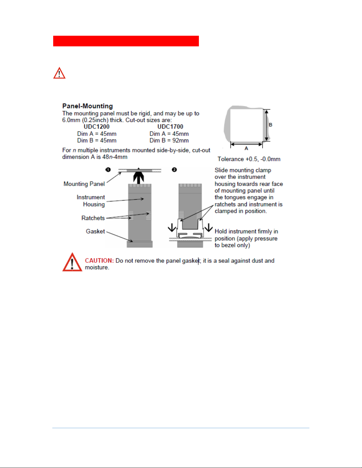
1. INSTALLATION
Page 3
3
UDC 1200 Start-up Guide Rev 2
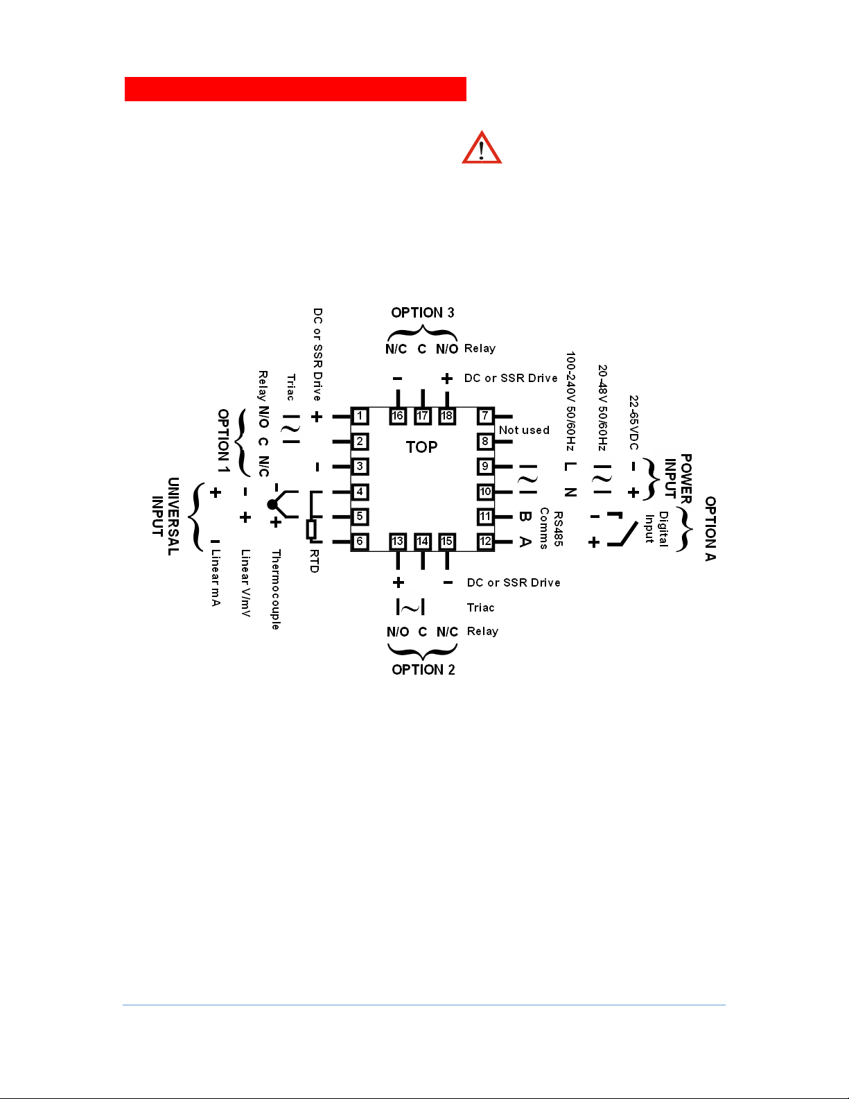
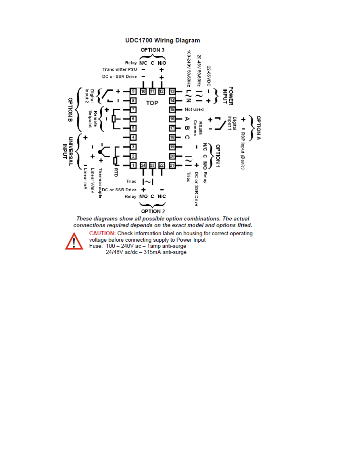
Rear Terminal Wiring
USE COPPER CONDUCTORS
(EXCEPT FOR T/C INPUT)
Single Strand wire gauge:
Max 1.2mm (18SWG)
UDC 1200
CAUTION: Check information label on
housing for correct operating voltage before
connecting supply to Power Input
Fuse: 100 – 240V ac – 1amp anti-surge
24/48V ac/dc – 315mA anti-surge
2. WIRING
Page 4
4
UDC 1200 Start-up Guide Rev 2
Page 5
5
UDC 1200 Start-up Guide Rev 2
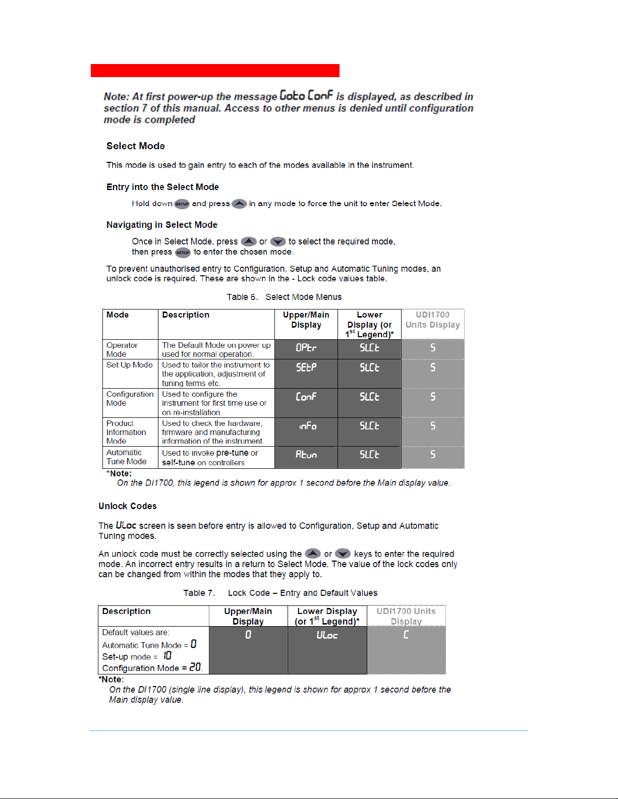
3. SELECT MODE
Page 6
6
UDC 1200 Start-up Guide Rev 2
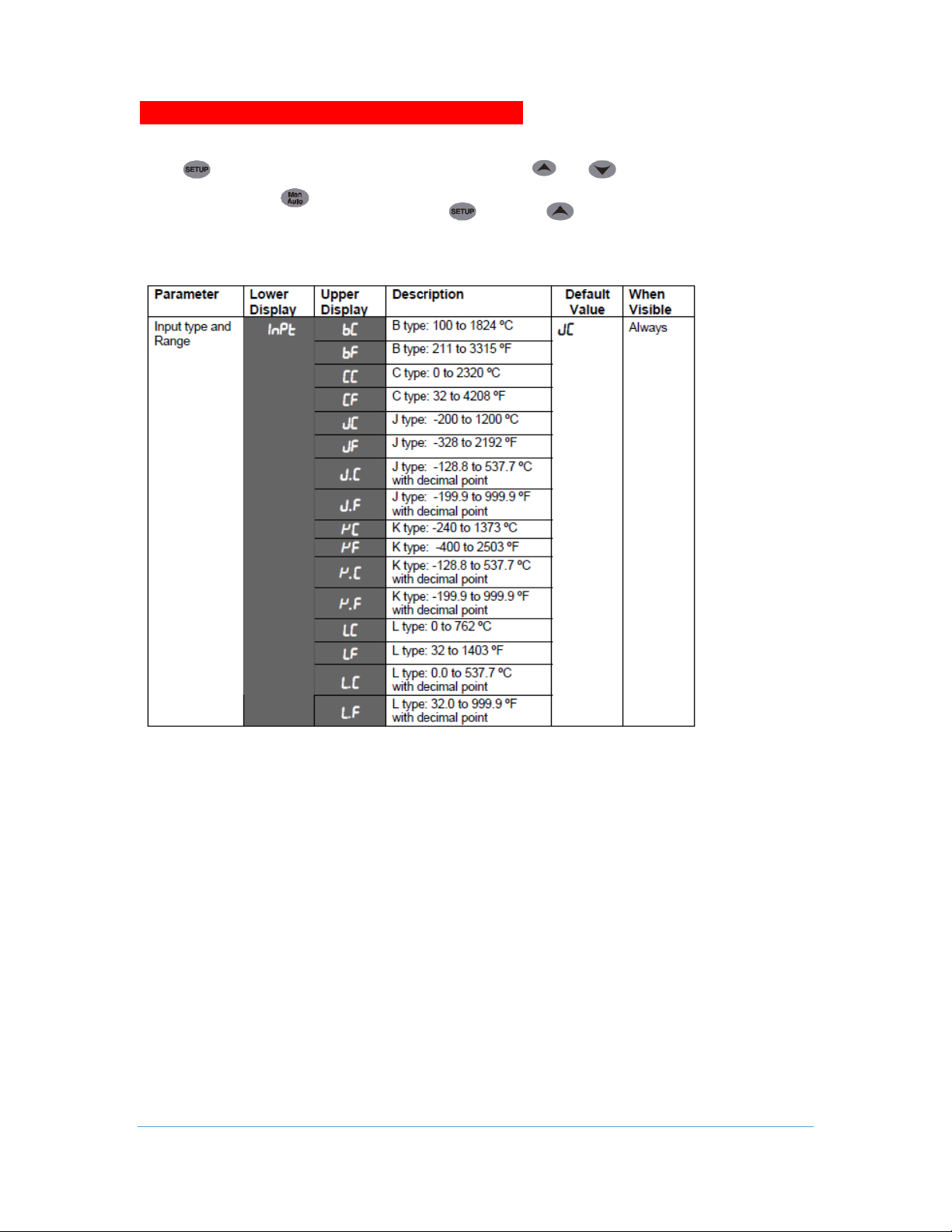
First select Configuration mode from Select mode (refer to section 2).
First select Configuration mode from Select mode (refer to section 3).
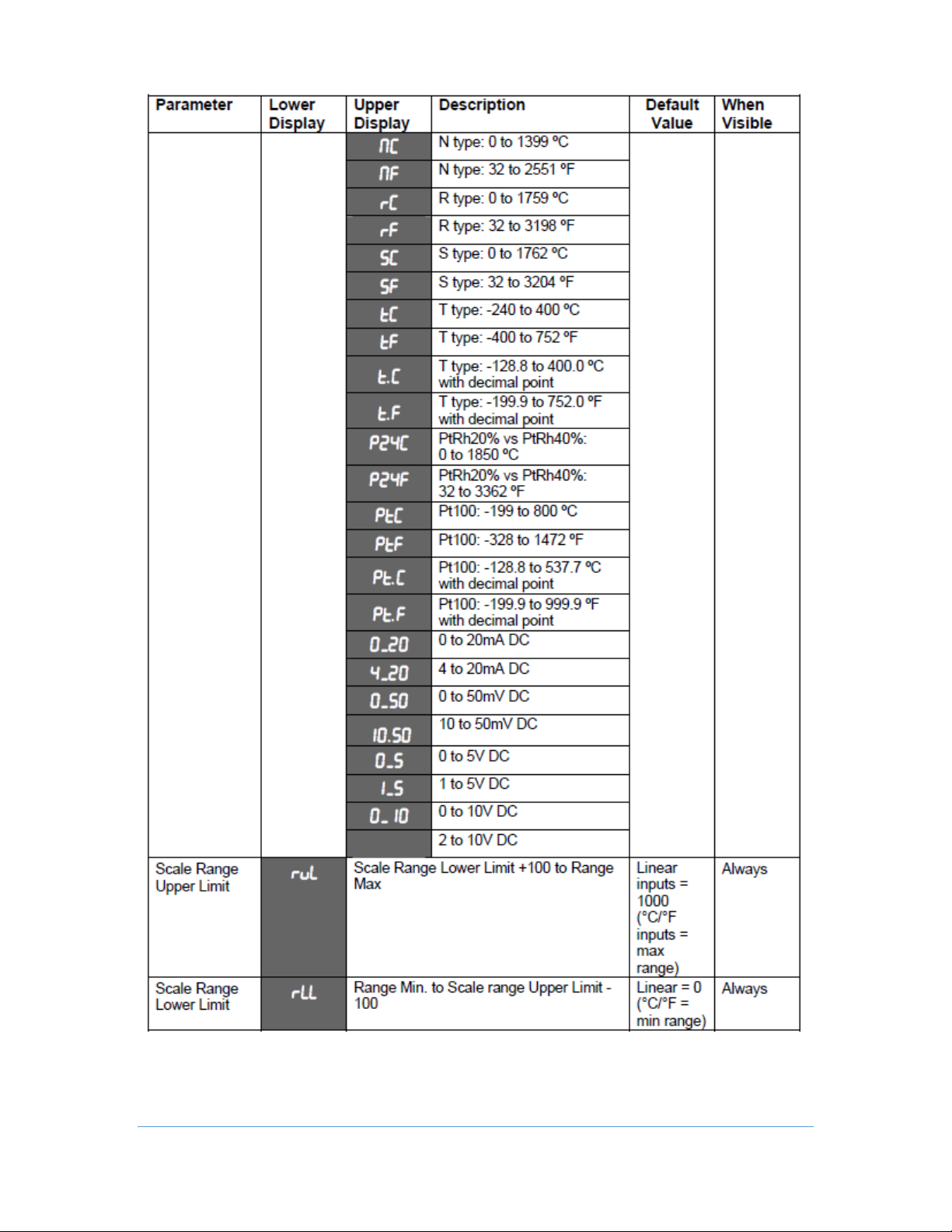
Press to scroll through the parameters, then press or to set the required value.
To accept a change must be pressed, otherwise parameter will revert to previous value.
To exit from Configuration mode, hold down and press , to return to Select mode.
Note: Parameters displayed depends on how instrument has been configured.
Parameters marked * are repeated in Setup Mode.
4. CONFIGURATION MODE
Page 7
7
UDC 1200 Start-up Guide Rev 2
Page 8

8
UDC 1200 Start-up Guide Rev 2
Page 9

9
UDC 1200 Start-up Guide Rev 2
Page 10

10
UDC 1200 Start-up Guide Rev 2
Page 11

11
UDC 1200 Start-up Guide Rev 2
* Refer to the full user guide for further details on these parameters.
Page 12

12
UDC 1200 Start-up Guide Rev 2
Note: Configuration must be completed before adjusting Setup parameters.
First select Setup mode from Select mode (refer to section 3). While in Setup Mode is lit.
Press to scroll through the parameters, then press or to set the required value.
To exit from Setup mode, hold down and press , to return to Select mode.
Note: Parameters displayed depends on how instrument has been configured.
5. SETUP MODE
Page 13

13
UDC 1200 Start-up Guide Rev 2
Page 14

14
UDC 1200 Start-up Guide Rev 2
Page 15

15
UDC 1200 Start-up Guide Rev 2
This mode is entered at power on. It can also be accessed from Select mode
(see section 3).
Note: All configuration mode and Setup mode parameters must be set as
required before starting normal operations.
Press to scroll through the parameters, then press or to set the
required value.
Note: All parameters in Display strategy 6 are read only, and can only be
adjusted via Setup mode.
6. OPERATOR MODE
Page 16

16
UDC 1200 Start-up Guide Rev 2
7. AUTOMATIC TUNING MODE
Page 17

17
UDC 1200 Start-up Guide Rev 2
Co
Continued on next page.
8. PRODUCT INFORMATION MODE
Page 18

18
UDC 1200 Start-up Guide Rev 2
Page 19

19
UDC 1200 Start-up Guide Rev 2
Installing Option Modules
To access modules 1 or A, first detach the PSU and CPU boards from the front moulding by lifting
first the upper, and then lower mounting struts. Gently separate the boards.
a). Plug the required option modules into the correct connectors, as shown below.
b). Locate the tongues on each module into the corresponding slot in the board opposite.
c). Hold the main boards together while relocating them back on the mounting struts.
d). Replace the instrument by aligning the CPU and PSU boards with their guides in the
housing, then slowly push the instrument back into position.
Note: The instrument will automatically detect which option modules have been fitted.
CAUTION: Turn off all power. Remove instrument by gripping the sides of the front panel and pulling the
instrument out of its housing. Note its orientation.
CPU PCB
Option Module 1
Option Module 2
Option Module A
Option Module 3
PSU PCB
Mounting Struts
9. Installing Option Modules
Option Module 3
Connector PL4B
Option Module 2
Connector PL4A
Option Module A
Connectors PL5 & PL6
Option Module 1
Connectors PL7 & PL8
Page 20

20
UDC 1200 Start-up Guide Rev 2
10. ERROR/FAULT INDICATIONS
Page 21

21
UDC 1200 Start-up Guide Rev 2
11. LOST LOCK CODE/ PASSWORD
 Loading...