

Honeywell TX 77042 Installation Manual

SmartLine Wireless Transmitter
Professional Installation Guide
34-SW-25-03
Revision 2
December 2019
Honeywell Process Solutions

Notices and Trademarks
Copyright 2019 by Honeywell International Inc.
Revision 2, December 2019
While this information is presented in good faith and believed to be accurate, Honeywell disclaims the implied
warranties of merchantability and fitness for a particular purpose and makes no express warranties except as may
be stated in its written agreement with and for its customers.
In no event is Honeywell liable to anyone for any indirect, special or consequential damages. The information and
specifications in this document are subject to change without noti ce.
Honeywell, PlantScape, Experion PKS, and TotalPlant are registered trademarks of Honeywell International Inc.
Other brand or product names are trademarks of their respective owners.
Honeywell Process Solutions
1250 W Sam Houston Pkwy S
Houston, TX 77042
ii SmartLine Wireless Transmitter Professional Installation Guide Revision 2
About This Document
This document outlines professional installation requirements for the SmartLineTM Wireless Pressure
Transmitter
for the Honeywell OneWireless Network. Professional installation is required to comply with
certification
agency and legal requirements. This document must be adhered to for all installations of the Honeywell
SmartLine Wireless Transmitters.
Honeywell does not recommend using devices for critical control where there is a single point of failure
or where single points of failure result in unsafe conditions. OneWireless is targeted at open loop
control, supervisory control, and controls that do not have environmental or safety consequences. As
with any process control solution, the end-user must weigh the risks and benefits to determine if the
products used are the right match for the application based on security, safety, and performance.
Additionally, it is up to the end-user to ensure that the control strategy sheds to a safe operating condition
if any crucial segment of the control solution fails.
Revision Information
Document Name
SmartLine Wireless Transmitter Professional Installation
Guide
1st release Revision 1 December 2018
Refs to wireless temperature transmitter models added Revision 2 December 2019
Document ID
34-SW-25-03
Revision Number
Publication Date
References
The following list identifies all documents that may be sources of reference for mater ia l discussed in this
publication.
Document Title Doc #
SmartLine Wireless Pressure Transmitter User’s manual
SmartLine Wireless Temperature Transmitter User ’s manual
OneWireless R310 Release Notes
OneWireless R310 Migration Users Guide
OneWireless R310 Field Device Access Point Users Guide
34-SW-25-01
34-SW-25-04
OWDOC-X252-en-310A
OWDOC-X258-en-310
OWDOC-X256-en-310
OneWireless R310 Wireless Device Manager Users Guide
OneWireless R300 Experion PKS Integration Guide
OneWireless R300 Wireless LAN Controller Configuration Guide
OneWireless R300 Network Planning an Installation Guide
Revision 2 SmartLine Wireless Transmitter Professional Installation Guide iii
OWDOC-X254-en-310
OWDOC-X259-en-300
OWDOC-X255-en-300
OWDOC-X253-en-300
Support and contact info
For Europe, Asia Pacific, North and South America contact details, refer to the back page of this
manual or the appropriate Honeywell Support web site:
Honeywell Corporate www.honeywell.com
Honeywell Process Solutions https://www.honeywellprocess.com/*
Training Classes https://www.honeywellprocess.com/en-US/training
Telephone and Email Contacts
Area Organization Phone Number
United States and
Canada
Global Email
Support
Honeywell Inc.
Honeywell Process Solutions
1-800-343-0228 Customer Service
1-800-423-9883 Global Technical Support
hfs-tac-support@honeywell.com
iv SmartLine Wireless Transmitter Professional Installation Guide Revision 2
manual.
manual.
local electrical code requirements.
national and local electrical code require men ts.
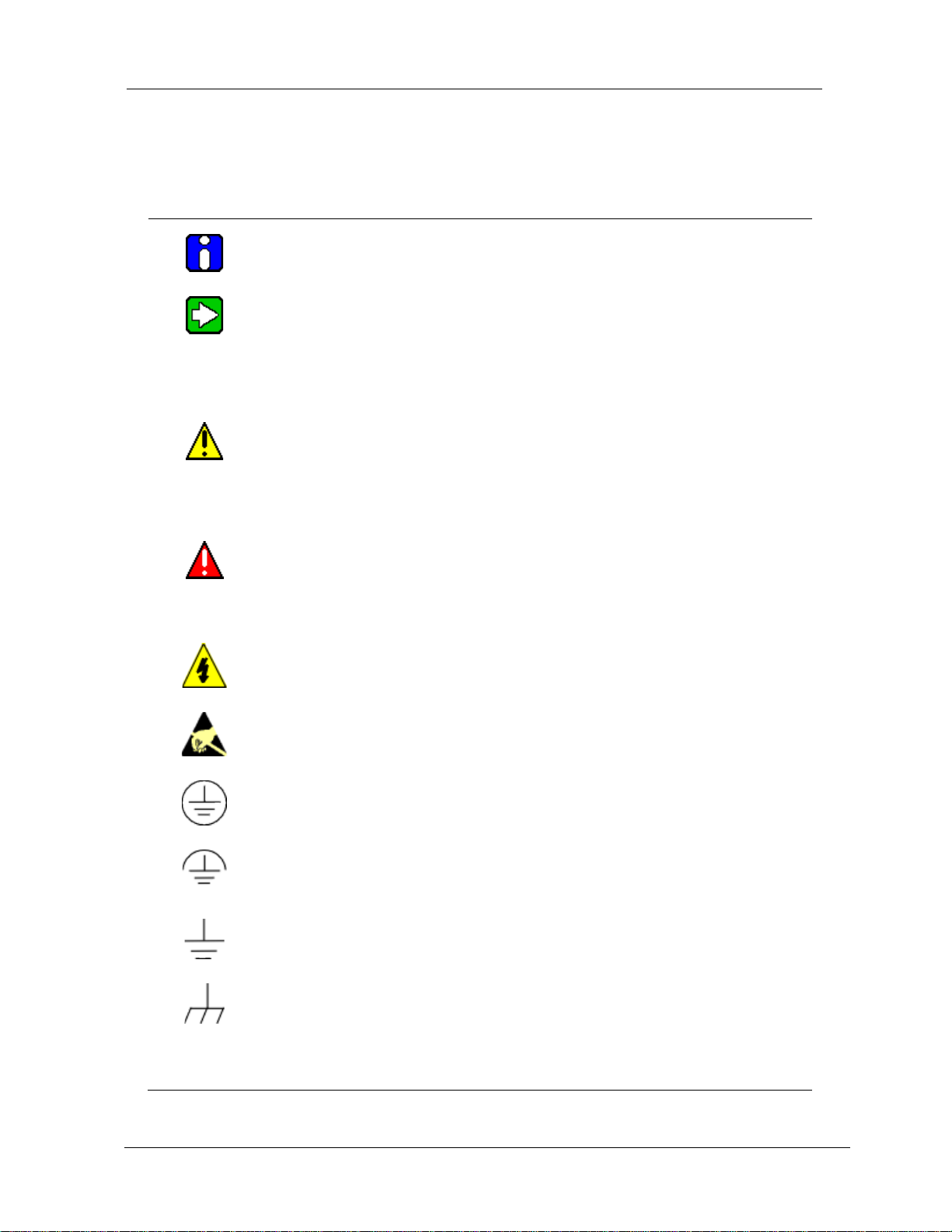
Symbol Definitions
The following table lists those symbols used in this document to denote certain conditions.
Symbol Definition
ATTENTION: Identifies information that requires special consideration.
TIP: Identifies advice or hints for the user, often in terms of performing a task.
CAUTION
Indicates a situation which, if not avoided, may result in equipment or work (data) on
the system being damaged or lost, or may result in the inability to properly operate
the process.
CAUTION: Indicates a potentially hazardous situation which, if not avoided, may
result in minor or moderate injury. It may also be used to alert against unsafe
practices.
CAUTION symbol on the equipment refers the user to the product manual for
additional information. The symbol appears next to required information in the
WARNING: Indicates a potentially hazardous situation, which, if not avoi ded, co uld
result in serious injury or death.
WARNING symbol on the equipment refers the user to the product manual for
additional information. The symbol appears next to required information in the
WARNING, Risk of electrical shock: Potential shock hazard where HAZARDOUS
LIVE voltages greater than 30 Vrms, 42.4 Vpeak, or 60 VDC may be accessible.
ESD HAZARD: Danger of an electro-static discharge to which equipment may be
sensitive. Observe precautions for handling electrostatic sen sitiv e dev ice s.
Protective Earth (PE) terminal: Provided for connection of the protective earth
(green or green/yellow) supply system conductor.
Functional earth terminal: Used for non-safety purposes such as noise immunity
continued
Revision 2 SmartLine Wireless Transmitter Professional Installation Guide v
improvement. NOTE: This connection shall be bonded to Protective Earth at the
source of supply in accordance with national local electrical code requirements.
Earth Ground: Functional earth connection. NOTE: This connection shall be
bonded to Protective Earth at the source of supply in accordance with national and
Chassis Ground: Identifies a connection to the chassis or frame of the equipment
shall be bonded to Protective Earth at the source of supply in accordance with

Symbol Description
The Factory Mutual® Approval mark means the equipment ha s
been rigorously tested and certified to be reliable.
The Canadian Standards mark means the equipment has been
tested and meets applicable standards for safety and/or
performance.
The Ex mark means the equipment complies with the requirements
of the European standards that are harmonized with the 94/9/EC
Directive (ATEX Directive, named after the French "ATmosphere
EXplosible").
For radio equipment used in the European Union in accordance
with the R&TTE Directive the CE Mark and the notified body (NB)
identification number is used when the NB is involved in the
conformity assessment procedure. The alert sign must be used
when a restriction on use (output power limit by a country at certa in
frequencies) applies to the equipment and mu st follow the CE
marking.
The ISA100 Wireless Compliant logo indicates the device has
received ISA100.11a conformance certification and is registered
with the Wireless Compliance Institute, assuring device
interoperability.
CRN Canadian Registration Number
vi SmartLine Wireless Transmitter Professional Installation Guide Revision 2

Contents
Contents
1. DESIGNATION, SCOPE AND PREFACE ............................................................ 1
1.1 Designation .................................................................................................................................. 1
1.2 Scope ............................................................................................................................................ 2
1.3 Preface ......................................................................................................................................... 2
1.4 Site survey ................................................................................................................................... 2
1.5 Abbreviations & Definitions ....................................................................................................... 3
2. FEDERAL COMMUNICATION COMMISSI ON (FCC) .......................................... 5
2.1 FCC Compliance Statement ....................................................................................................... 5
2.2 Industry Canada (IC) ................................................................................................................... 5
2.2.1 IC Compliance Statements ................................................................................................................... 5
2.2.2 RF Safety Statement ............................................................................................................................ 5
2.3 FCC and Industry Canada (IC) Identification Numbers ........................................................... 6
2.3.1 ISA100 Radios ...................................................................................................................................... 6
2.4 Intended Country Usage ............................................................................................................. 6
2.4.1 NORTH AMERICA ............................................................................................................................... 6
2.4.2 EUROPEAN UNION ............................................................................................................................. 6
3. SMARTLINE WIRELESS TRANSMITTER GENERAL DESCRIPTION ............... 7
3.1 Intended Used .............................................................................................................................. 7
3.2 SmartLine Wireless Transmitter ................................................................................................ 7
4. PRODUCT SPECIFICATION ................................................................................ 8
4.1 ISA100 Radio, 2.4 GHz ................................................................................................................ 8
4.2 SmartLine Wireless Transmitter User Environment ................................................................ 9
4.3 SmartLine Wireless Instrument Power S pecifications ............................................................ 9
4.4 Weight .......................................................................................................................................... 9
4.5 Dimensions ................................................................................................................................ 10
5. CABLES .............................................................................................................. 11
5.1 SmartLine Wireless Transmitter with N Connectors Antenna or Lightning Arrestor
Cables.................................................................................................................................................... 11
5.2 Transmitter connection status ................................................................................................. 11
5.3 Antenna Lightning Arrestors ................................................................................................... 12
Revision 2 SmartLine Wireless Transmitter Professional Installation Guide vii

Contents
6. APPROVED ANTENNA TYPES/GAINS ............................................................ 13
6.1 Antenna Details .......................................................................................................................... 13
7. EQUIVALENT ISOTROPICALLY RADIATED POWER (EIRP) ......................... 14
7.1 EIRP LIMITS ................................................................................................................................ 14
8. SETTING TX POWER ........................................................................................ 18
8.1 TX Power Setting ....................................................................................................................... 18
9. AGENCY LABEL INFORMATION...................................................................... 19
9.1 External FCC/IC Labels ............................................................................................................. 19
9.1.1 External FCC/IC Label ........................................................................................................................ 19
10. RF SAFETY, MAXIMUM PERMISSIBLE EXPOSURE (MPE) STATEMENT ..... 20
10.1 MPE Statement ....................................................................................................................... 20
11. AGENCY COMPLIANCE .................................................................................... 21
11.1 Radio and EMC Certifications ............................................................................................... 21
11.1.1 Federal Communication Commission (FCC) ...................................................................................... 21
11.1.2 Industry Canada (IC) .......................................................................................................................... 21
11.1.3 European Telecommunications Standards Institute (ETSI) ................................................................ 21
11.2 Product Safety Agency Certifications ....................................................................................... 21
11.2.1 European Union Certification (CE-mark) ............................................................................................ 21
viii SmartLine Wireless Transmitter Professional Ins tallation Guide Revision 2

Contents
Tables
Table 1-1 – SmartLine Wireless Transmitter Types ..................................................................................... 1
Table 1-2 –Table of Abbreviations and Definitions ....................................................................................... 3
Table 4-1 Specifications of ISA100 Radio Module in SmartLine Wireless Transmitter................................ 8
Table 4-2 User Environment Specifications for SmartLine Wireless Transmitter ........................................ 9
Table 5-1 Transmitter to Antenna or Lightning Arrestor Cable Specifications for SmartLine Wireless with
N connectors ....................................................................................................................................... 11
Table 6-1 Approved Antenn a T ypes/Gai ns ................................................................................................ 13
Table 7-1 Maximum EIRP Limits for ISA100 Radios .................................................................................. 14
Table 7-2 ISA100 Transmit Power Settings for the antennas and cable lengths specified above ............. 16
Figures
Figure 3-1 SmartLine Wireless Pressure Transmitter showing 4 dBi Integral Antenna ............................... 7
Figure 4-1 Dimensions of a typical SmartLine Wireless Transmitter with the 4 dBi Integral Antenna
Option .................................................................................................................................................. 10
Figure 6-1 Remote Antennas...................................................................................................................... 13
Revision 2 SmartLine Wireless Transmitter Professional Ins tallation Guide ix

 Loading...