

Page 1
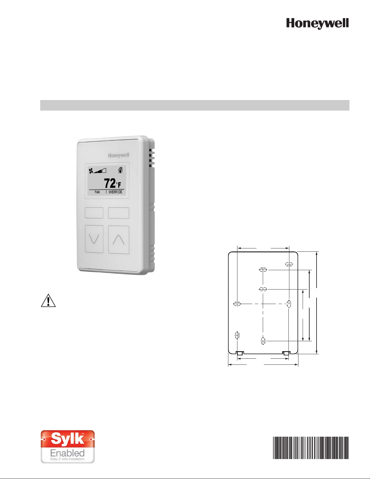
Zio® Lite TR40/42 LCD and
CAUTION
non-LCD Wall Modules
INSTALLATION INSTRUCTIONS
BEFORE INSTALLATION
Fig. 1. LCD Wall Module.
Erratic System Operation Hazard.
Failure to follow proper wiring practices can
introduce disruptive electrical interference (noise).
Keep wiring at least one foot away from large inductive
loads such as motors line starters, lighting ballasts,
and large power distribution panels.
Shielded cable is required in installations where these
guidelines cannot be met.
Ground the shield only to the grounded controller
case.
IMPORTANT
All wiring must comply with local electrical codes and
ordinances or as specified on installation wiring diagrams.
— For information on Sylk bus distance limitations, see
Table 1 on page 2.
— All wiring is polarity insensitive.
INSTALLATION
Mount the wall module on an inside wall approximately 54 in.
(1372 mm) from the floor (or in the specified location), to allow
exposure to the average zone temperature. Do not mount the
wall module on an outside wall, on a wall containing water
pipes, or near air ducts. Avoid locations that are exposed to
discharge air from registers or radiation from appliances,
lights, or the sun.
The wall module can be mounted on a wall, on a standard
utility conduit box using No. 6 (3.5 mm) screws or on a 60 mm
wall outlet box (see Fig. 3). When mounting directly on a wall,
use the type of screws appropriate for the wall material.
2-3/8 (60)
4-41/64
(118)
3-1/4
(83)
2-3/8
(60)
2-3/8 (60)
3-11/64 (81)
Fig. 2. Subbase mounting holes and locking tabs.
M34633
62-0467-05
Page 2
ZIO® LITE TR40/42 LCD AND NON-LCD WALL MODULES
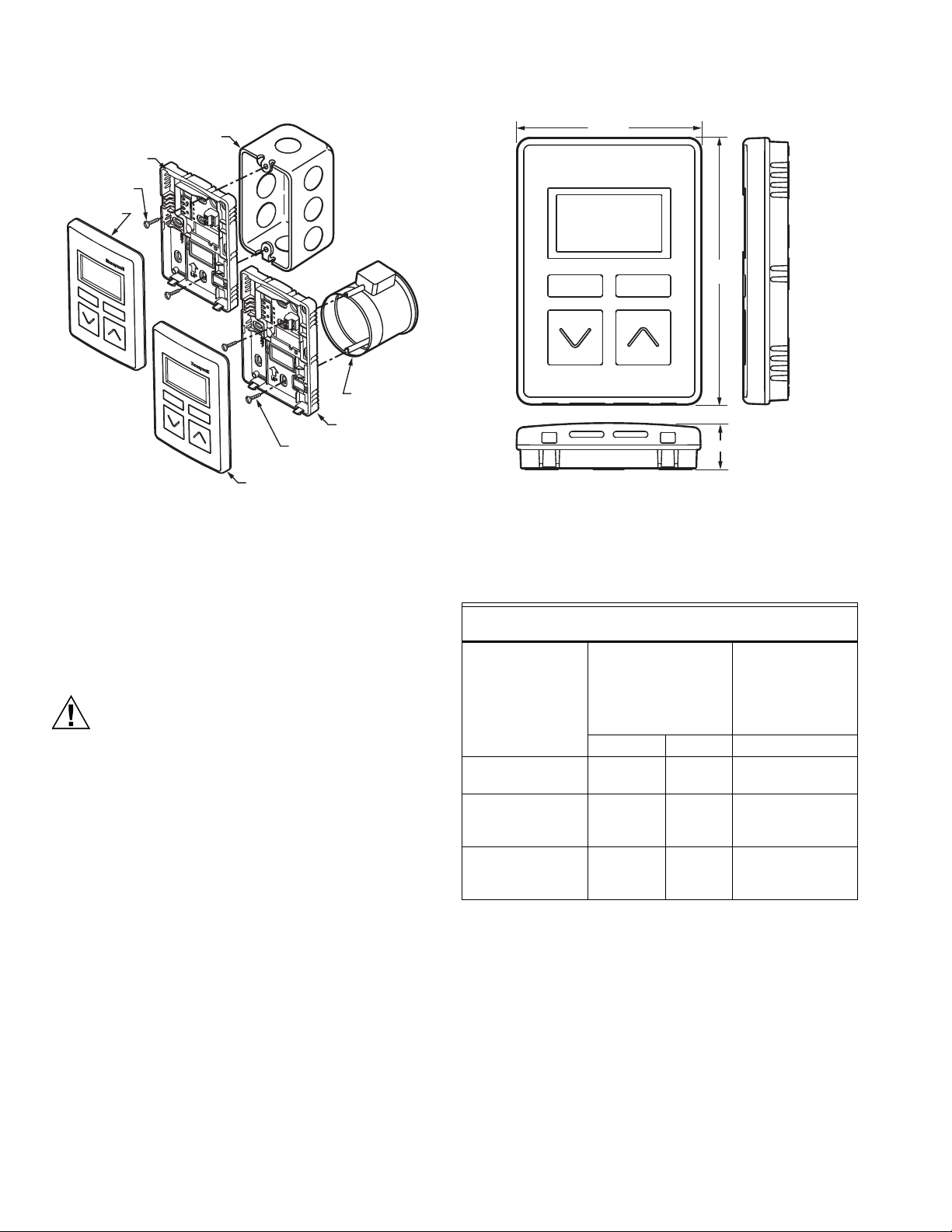
CAUTION
M34634
STANDARD UTILITY
CONDUIT BOX
SUBBASE
NO. 6 SCREW
60 mm WALL
OUTLET BOX
SUBBASE
3.5 mm SCREW
WALL MODULE
WALL
MODULE
53/64 (21)
M34635
3-5/16 (84)
4-49/64
(121)
Fig. 3. Mounting on standard utility conduit box or
60 mm wall outlet box.
Fig. 4. LCD Wall Module dimensions in inches (mm).
Wiring
All terminal connections can be made to the backside of the
module. There are no field adjustable/replaceable
components inside the module.
Attach the wires from the programmable controller and
network to the appropriate wall module terminals, as indicated
in Fig. 6 on page 3.
Improper Electrical Contact Hazard.
Screw-type terminal blocks are designed to accept
no more than one 14AWG (2.5mm sq) conductor.
Connect multiple wires that are 14AWG (2.5mm sq)
with a wire nut. Include a pigtail with this wire group
and attach the pigtail to the individual terminal block.
Wiring Wall Modules
Wire the terminal block shown in Fig. 6 as follows:
1. For single wires, strip 3/16 in. (5 mm); for multiple wires
going into one terminal, strip 1/2 in. (13 mm) insulation
from the conductor. See Fig. 5 for wiring multiple
TR40/42s.
2. Insert the wire in the required terminal location and
tighten the screw to complete the termination.
3. Review and verify the terminal connection wiring
illustrated in Fig. 6.
Table 1.
Recommended maximum distance
from controller to any Sylk device
Standard
thermostat wire,
(non-twisted),
Single twisted pair,
non-shielded,
Quantity and type
of device
a
10 wall modules,
any type
4 Sylk field devices
of any type
(including Zelix)
10 Sylk field
devices of any type
(excluding Zelix)
a
For Spyders, use the Resource Usage View in the Spyder Tool
stranded or solid
18-22 AWG 24 AWG 18-24 AWG
500 ft
(150 m)
400 ft
(120 m)
400 ft
(120 m)
400 ft
(120 m)
300 ft
(100 m)
300 ft
(100 m)
shielded or non-
shielded, stranded
b
or solid
c,d
100 ft
(30 m)
100 ft
(30 m)
100 ft
(30 m)
to determine the maximum number of devices. For ComfortPoint™ Open controllers, there is a maximum of 3 TR40/42s.
b
As a rule of thumb, single twisted pair (2 wires per cable
only), thicker gauge, non-shielded cable yields best results
for longer runs.
c
The 30 m distance for standard thermostat wire is conserva-
tive, but meant to reduce the impact of any sources of electrical noise (including but not limited to VFDs, electronic
ballasts, etc). Shielded cable recommended only if there is a
need to reduce the effect of electrical noise.
d
These distances also apply for shielded twisted pair.
62-0467—05 2
Page 3

TWO WIRES INTO ONE TERMINAL
1.
1/2
(13)
DAISY-CHAINING MULTIPLE ZIOS HOME RUNNING MULTIPLE ZIOS
STRIP 1/2 IN.
(13MM) FROM
WIRES TO BE
ATTACHED AT
ONE TERMINAL.
2.
TWIST WIRES
TOGETHER
WITH PLIERS
(A MINIMUM OF
THREE TURNS).
WALL MODULE
TERMINALS
3.
CUT TWISTED END OF WIRES TO
3/16 IN. (5 MM) BEFORE INSERTING
INTO TERMINAL AND TIGHTENING
SCREW. THEN PULL ON EACH WIRE
IN ALL TERMINALS TO CHECK FOR
GOOD MECHANICAL CONNECTION.
ZIO® LITE TR40/42 LCD AND NON-LCD WALL MODULES
bus address (1-15). Use the bus address label, shown in Fig.
7, as a reference. The default address for both TR40 and
TR42 is 1. The address on the wall module must match the
address in the configuration tool.
TO CONTROLLER
TO ZIO
TO CONTROLLER
M27348A
Fig. 5. Options for Wiring Multiple TR40/42s.
M34805
Fig. 6. Terminal connections.
M34637
Fig. 7. Bus address settings label.
Attaching the Wall Module to the Subbase
When all wiring is complete, hook the top side, and then snap
down like on a hinge. See Fig. 8.
Removing the Wall Module from Subbase
To remove the wall module from its subbase:
1. Locate the two snaps on the bottom of the IFC .
2. Push a screwdriver into each snap to release the IFC
from the subbase.
3. Pull the wall module up and away from the subbase.
See Fig. 8.
WALL
Setting the Wall Module Bus Address Dial
Each wall module on a Sylk bus must use a different bus
address, and there may be multiple TR40/42s wired on a
single Sylk bus. To change the bus address of a wall module,
adjust the address dipswitches to match that of the desired
M34638
Fig. 8. Removing Wall Module from Subbase.
3 62-0467—05
Page 4

ZIO® LITE TR40/42 LCD AND NON-LCD WALL MODULES
M34639
M34640
M34641
POWER UP
After the wall module is properly wired to the controller, it will
power up. Upon initial power up, the wall module’s LCD panel
displays three screens for two seconds each, shown in Figs.
9-11, while the configuration file is being loaded. Once the
configuration file has been loaded and the startup screens
have cycled through, the LCD panel will then display the home
screen. If these screens continuously cycle, this indicates
there is no program downloaded to the controller, or the bus
addresses don't match between the wall module and the
workbench config tool.
For Spyder/Niagara tool users, refer to the TR40/42/TR40/42
Plus LCD Wall Modules Operating Guide (Form 63-2741) to
configure and load the desired user interface and parameters
into the wall module.
For ComfortPoint™ Open users, the user interface and
parameters are downloaded automatically from the
ComfortPoint Open controller. There is no configuration required
at the wall module.
Fig. 10. TR42 Wall Module LCD display startup screen 2.
Fig. 9. TR42 Wall Module LCD display startup screen 1.
Fig. 11. TR42 Wall Module LCD display startup screen 3.
ComfortPoint™ is a trademark of Honeywell International Inc.
L
ONMARK® is a trademark of the LonMark Association.
BACnet® is a trademark of BACnet International.
Sylk® is a trademark of Honeywell International Inc.
TR40/42® is a trademark of Honeywell International Inc.
By using this Honeywell literature, you agree that Honeywell will have no liability for any damages arising out of your use or modification to,
the literature. You will defend and indemnify Honeywell, its affiliates and subsidiaries, from and against any liability, cost, or damages,
including attorneys’ fees, arising out of, or resulting from, any modification to the literature by you.
Automation and Control Solutions
Honeywell International Inc.
® U.S. Registered Trademark
© 2014 Honeywell International Inc.
62-0467—05 M.S. 05-14
Printed in United States
 Loading...