

Page 1
Technical Handbook
Touchpoint Pro
Page 2

Revision
Comment
Date
Issue 1
A04483
Jan 2015
Issue 2
A04522
Mar 2015
Issue 3
A04548
July 2015
Issue 4
A04815
Nov 2016
Issue 5
A05034
Oct 2017
Issue 6
A05082
Mar 2018
REVISION HISTORY
Part. No. 2400M2501_6 Touchpoint Pro
i Technical Handbook
Page 3

LEGAL NOTICES
Disclaimer
In no event shall Honeywell be liable for any damages or injury of any nature or kind, no matter how caused, that arise from
the use of the equipment referred to in this manual.
Strict compliance with the safety procedures set out and referred to in this manual, and extreme care in the use of the
equipment, are essential to avoid or minimise the chance of personal injury or damage to the equipment.
The information, figures, illustrations, tables, specifications, and schematics contained in this manual are believed to be
correct and accurate as at the date of publication or revision. However, no representation or warranty with respect to such
correctness or accuracy is given or implied and Honeywell will not, under any circumstances, be liable to any person or
corporation for any loss or damages incurred in connection with the use of this manual.
The information, figures, illustrations, tables, specifications, and schematics contained in this manual are subject to change
without notice.
Unauthorised modifications to the gas detection system or its installation are not permitted, as these may give rise to
unacceptable health and safety hazards.
By installing this equipment on a computer network, the owner accepts full and unequivocal responsibility for ensuring that it
is protected against all cyber threats and illegal tampering during the lifetime of the equipment.
Any software forming part of this equipment should be used only for the purposes for which Honeywell supplied it. The user
shall undertake no changes, modifications, conversions, translations into another computer language, or copies (except for a
necessary backup copy).
In no event shall Honeywell be liable for any equipment malfunction or damages whatsoever, including (without limitation)
incidental, direct, indirect, special, and consequential damages, damages for loss of business profits, business interruption,
loss of business information, or other pecuniary loss, resulting from any violation of the above prohibitions.
Warranty
Honeywell Analytics warrants the Touchpoint Pro system against defective parts and workmanship, and will repair or (at its
discretion) replace any components that are or may become defective under proper usage within 12 months from the date of
commissioning by a Honeywell Analytics approved representative* or 18 months from shipment from Honeywell Analytics,
whichever is sooner.
This warranty does not cover consumables, batteries, fuses, normal wear and tear, or damage caused by accident, abuse,
improper installation, unauthorized use, modification or repair, ambient environment, poisons, contaminants or abnormal
operating conditions.
This warranty does not apply to sensors or components that are covered under separate warranties, or to any 3rd-party
cables and components.
Any claim under the Honeywell Analytics Product Warranty must be made within the warranty period and as soon as
reasonably practicable after a defect is discovered. Please contact your local Honeywell Analytics Service representative to
register your claim.
This is a summary. For full warranty terms please refer to the Honeywell Analytics’ General Statement of Limited Product
Warranty, which is available on request.
* A Honeywell Analytics approved representative is a qualified person trained or employed by Honeywell Analytics, or a
qualified person trained in accordance with this manual.
Copyright Notice
Microsoft, MS and Windows are registered trademarks of Microsoft Corp.
Other brand and product names mentioned in this manual may be trademarks or registered trademarks of their respective
companies and are the sole property of their respective holders.
Touchpoint is a registered trademark of Honeywell Analytics (HA).
Find out more at www.honeywellanalytics.com
Part. No. 2400M2501_6 Touchpoint Pro
ii Technical Handbook
Page 4

Contents
CONTENTS
1 Important Safety Information ......................................................................................................... 1
1.1 International Standards ....................................................................................................... 1
1.2 Warnings ............................................................................................................................. 2
1.3 Cautions .............................................................................................................................. 3
2 Safety Hazards, Warnings and Cautions ....................................................................................... 5
2.1 Safety .................................................................................................................................. 5
2.2 Location and Description of Warning Labels ....................................................................... 8
3 Touchpoint Pro Introduction ................................ ........................................................................ 11
3.1 TPPR Access Levels ........................................................................................................ 11
3.2 TPPR Control System Layout ........................................................................................... 12
3.3 TPPR System Key Components ....................................................................................... 14
3.4 Power Supply Options ...................................................................................................... 20
4 TPPR Mechanical Installation ...................................................................................................... 25
4.1 TPPR Siting Considerations ............................................................................................. 25
4.2 Installing Wall Mounted Enclosures .................................................................................. 26
4.3 Installing Floor Standing Enclosures ................................................................................. 28
4.4 Installing the TPPR 19". Rack Mounted Unit ..................................................................... 29
4.5 Installing the TPPR Panel Mount Controller ...................................................................... 30
4.6 Installing the Battery Enclosure......................................................................................... 31
5 TPPR Electrical Installation .......................................................................................................... 33
5.1 Power Requirements ........................................................................................................ 33
5.2 Cabling Requirements ...................................................................................................... 34
5.3 Controller Electrical Connections ...................................................................................... 45
5.4 First Time Switch On ......................................................................................................... 49
6 Modbus Installation (Option) ........................................................................................................ 50
6.1 Introduction ....................................................................................................................... 50
6.2 Programming the Host ...................................................................................................... 50
6.3 Addressing Conventions and Register Values .................................................................. 50
6.4 Modbus Bus Interface Board (BIB) Installation ................................................................. 51
6.5 Modbus Cables ................................................................................................................. 53
6.6 Modbus Electrical Connections ......................................................................................... 53
6.7 Modbus RTU Connections ................................................................................................ 53
6.8 Modbus Termination Resistor ........................................................................................... 53
6.9 Modbus Configuration Examples ...................................................................................... 54
6.10 Modbus Jumper Settings and Termination Resistor Fitting ............................................... 55
6.11 Modbus Multi-Drop Mode .................................................................................................. 55
7 Software Setup and Commissioning ........................................................................................... 56
7.1 How to Setup or Change the Touchscreen Panel Configuration: ...................................... 56
7.2 How to Calibrate the Touchscreen .................................................................................... 56
7.3 How to Edit Service Contact Settings ............................................................................... 57
Part. No. 2400M2501_6 Touchpoint Pro
iii Technical Handbook
Page 5

CONTENTS
7.4 Configuring the Touchpoint Pro TCP/IP Address and Printer ........................................... 57
7.5 Enabling TPPR’s Remote Connection Port ....................................................................... 58
7.6 How to Print Active Events ................................................................................................ 58
8 Calibrating Gas Sensors ............................................................................................................... 59
8.2 Calibrating AIM-mV Input Channels .................................................................................. 60
8.3 Calibrating AIM-mA Input Channel Loops ......................................................................... 62
9 Configuring System Parameters .................................................................................................. 65
9.1 General Considerations .................................................................................................... 65
9.2 Analogue Input Module 4-20 mA Parameters ................................................................... 66
9.3 Analogue Input Module mV Bridge Parameters ................................................................ 75
9.4 Digital Input Module Parameters ....................................................................................... 82
9.5 Relay Output Module Parameters ..................................................................................... 84
9.6 Cause & Effect Matrix ....................................................................................................... 85
9.7 Control of Output Channels – Priority ............................................................................... 91
9.8 Power Supply Unit Parameters ......................................................................................... 91
10 Configuring STEL and LTEL Alarms ........................................................................................... 92
10.1 STEL Operation ................................................................................................................ 92
10.2 LTEL Operation................................................................................................................. 93
11 Configuring Modbus ..................................................................................................................... 96
11.1 Modbus Register Allocation for Function 02 – Read Input Status ..................................... 96
11.2 Modbus Register Allocation for Function 04 – Read Input Registers ................................ 97
11.3 Register Allocation for Function 03 / 06 / 16 – Read / Write Holding Registers ................ 98
11.4 Command Types ............................................................................................................. 100
11.5 Exception Responses ..................................................................................................... 101
12 Configuration Files...................................................................................................................... 102
12.1 Viewing and Editing the Configuration ............................................................................ 102
12.2 To Back Up the Configuration ......................................................................................... 103
12.3 Restoring the Configuration ............................................................................................ 103
12.4 Deleting the Configuration .............................................................................................. 104
12.5 CCB Configuration Settings ................................ ................................ ............................ 105
13 Normal Day-to-Day Operation .................................................................................................... 107
13.1 TPPR Controller Touchscreen Interface ......................................................................... 107
13.2 TPPR PC Configuration Software Interface .................................................................... 107
13.3 TPPR Webserver Interface ............................................................................................. 107
13.4 TPPR Safety Function .................................................................................................... 108
13.5 Touchscreen Operation .................................................................................................. 108
13.6 How to Recalibrate the Touchscreen .............................................................................. 112
13.7 Touchscreen Calibration ................................................................................................. 112
13.8 How to View Input Channels and Input Details ............................................................... 112
13.9 How to View Output Channels ........................................................................................ 113
13.10 How to View the Trend Graph ......................................................................................... 114
13.11 How to View Event History .............................................................................................. 115
Part. No. 2400M2501_6 Touchpoint Pro
iv Technical Handbook
Page 6

CONTENTS
13.12 How to View Event Reports ............................................................................................ 115
13.13 How to Access Diagnostic information ............................................................................ 115
13.14 Managing the Integral SD Card....................................................................................... 116
13.15 Accessing Help ............................................................................................................... 117
13.16 System State Relays ....................................................................................................... 117
14 Alarms, Faults, Warnings and Inhibits ...................................................................................... 118
14.1 Latching Alarms .............................................................................................................. 118
14.2 STEL / LTEL Alarms ....................................................................................................... 118
14.3 Rate Alarm ...................................................................................................................... 119
14.4 Relay Activated Outputs ................................................................................................. 119
14.5 Sensor Over Range Operation........................................................................................ 120
14.6 Catalytic Sensor Over Range Operation ......................................................................... 120
14.7 Full Scale Exceeded and Over Range Warning Operation ............................................. 120
14.8 Special Considerations when using Catalytic Sensors ................................................... 122
14.9 Responding to Alarms, Faults and Warnings .................................................................. 124
14.10 Viewing Faults and Warnings.......................................................................................... 126
14.11 Inhibiting a Channel ........................................................................................................ 127
15 Maintenance Procedures ............................................................................................................ 129
15.1 Routine Maintenance ...................................................................................................... 129
15.2 Periodic Maintenance ..................................................................................................... 130
16 How to Test the TPPR System ................................................................................................... 131
16.1 Introduction ..................................................................................................................... 131
16.2 LED Panel Test ............................................................................................................... 132
16.3 Field Inputs Test ............................................................................................................. 132
16.4 Configuration Settings Test ............................................................................................. 133
16.5 Cause and Effect Test .................................................................................................... 134
16.6 Panel Button Test ........................................................................................................... 135
16.7 System Relay Test .......................................................................................................... 135
16.8 LCD Screen Test ............................................................................................................ 136
16.9 How to Exercise the Output Relays ................................................................................ 136
16.10 How to Remove or Replace Modules .............................................................................. 137
16.11 How to Add or Install a New I/O Module ......................................................................... 140
16.12 How to Check the DC-UPS ............................................................................................. 141
16.13 How to Change the Battery Protection Fuse ................................................................... 142
16.14 How to Replace Batteries ............................................................................................... 142
17 System Troubleshooting ............................................................................................................ 143
17.1 Observed Problem .......................................................................................................... 143
17.2 Other Issues.................................................................................................................... 146
18 Error Codes ................................................................................................................................. 147
19 Ring Communication Errors ...................................................................................................... 158
19.1 Module Faults ................................................................................................................. 158
19.2 Troubleshooting Module Faults First Response .............................................................. 158
Part. No. 2400M2501_6 Touchpoint Pro
v Technical Handbook
Page 7

CONTENTS
19.3 Troubleshooting Module Faults Second Response ......................................................... 159
19.4 Ring Fault Diagnostics and Debugging Techniques ....................................................... 160
20 Further Assistance and Training ............................................................................................... 163
21 TPPR Specifications ................................................................................................................... 164
21.1 Rack Mounted Equipment ............................................................................................... 164
21.2 Wall Mounted Enclosures ............................................................................................... 166
21.3 Floor Standing Enclosures .............................................................................................. 168
21.4 Power Supplies and Fuses ............................................................................................. 169
21.5 Control Module and User Interface ................................................................................. 173
21.6 I/O Modules..................................................................................................................... 174
22 Certification ................................................................................................................................. 177
22.1 EU Declaration of Conformity.......................................................................................... 177
22.2 Applicable National and International Standards ............................................................ 177
22.3 National and International Certificates for Zone 2 Div. 2 ................................ ................. 178
22.4 European Performance Approval (DEKRA Exam) for Systems ...................................... 178
23 Ordering Information .................................................................................................................. 182
23.1 TPPR System ID Configuration....................................................................................... 182
23.2 TPPR Components Part Numbers .................................................................................. 183
24 Disposal of Redundant / Unserviceable Parts .......................................................................... 184
24.1 Restriction of Hazardous Substances (RoHS) Directive ................................................. 184
24.2 Waste Electrical and Electronic Equipment (WEEE) Directive ........................................ 184
24.3 TPPR System Construction ............................................................................................ 184
25 Table of Icons .............................................................................................................................. 186
26 List of Illustrations ................................................................ ...................................................... 188
27 List of Tables ............................................................................................................................... 191
Part. No. 2400M2501_6 Touchpoint Pro
vi Technical Handbook
Page 8
SAFETY
WARNING
EQUIPMENT.
ATTENTION
D’UTILISER, D’ENTRETENIR OU DE RÉPARER L’ÉQUIPEMENT.
1 Important Safety Information
The Equipment referred to in this manual contains components and assemblies that are each certified for use in a variety of
differing environments, and it is the site owner’s responsibility to confirm the suitability of the equipment and any associated
computer networks prior to its installation and use.
The Equipment assemblies referred to in this manual are collectively certified for use in a gas detection system only. Any
other use is not currently certified and is not authorised by the manufacturer.
For installation in Canada and the USA, for both ordinary and hazardous locations, all connections, cabling, overcurrent
protection and installations must strictly adhere to both the National Electrical Code (NEC) and the Canadian Electrical Code
(CEC).
Check the product rating plate and look for the following marks to ensure that the supplied equipment is suitable for its
intended location and purpose:
Products bearing the CE mark conform to all applicable European Directives as stated on the Honeywell product specific EU
Declaration of Conformity.
Products bearing the CSA mark conform to the requirements for Ordinary Locations, and where marked on components and
apparatus, Zone 2 and Division 2 Hazardous Locations.
Products, components and apparatus bearing the ATEX Explosion Protection mark conform to the requirements for Zone 2
Potentially Explosive Atmospheres.
FOR SAFETY REASONS THIS EQUIPMENT MUST BE OPERATED BY QUALIFIED PERSONNEL ONLY. READ
AND UNDERSTAND THE INSTRUCTION MANUAL COMPLETELY BEFORE OPERATING OR SERVICING THE
POUR DES RAISONS DE SÉCURITÉ, CET ÉQUIPEMENT DOIT ÊTRE UTILISÉ, ENTRETENU ET RÉPARÉ
UNIQUEMENT PAR UN PERSONNEL QUALIFIÉ. ÉTUDIER LE MANUEL D’INSTRUCTIONS EN ENTIER AVANT
1.1 International Standards
All personnel should acquaint themselves with the contents of the following standards before commencing work on gas
detection systems:
IEC 60079-29-2, which gives guidance on, and recommended practice for, the selection, installation, safe use and
maintenance of electrically operated group II apparatus intended for use in industrial and commercial safety applications for
the detection and measurement of flammable gases complying with the requirements of EN 60079-29-1.
IEC 60079-20-1, which gives guidance on material characteristics for gas and vapour classification; test methods and data.
It also explains how to convert test and calibration gas (span gas) concentrations from %LFL to %v/v.
EN 45544-4, which gives guidance on electrical apparatus used for the direct detection and direct concentration
measurement of toxic gases and vapours and a guide for their selection, installation, use and maintenance.
Part. No. 2400M2501_6 Touchpoint Pro
1 Technical Handbook
Page 9

SAFETY
WARNINGS
1. For safety reasons this equipment must be operated by qualified personnel only. Read and understand the
Instruction Manual completely before operating or servicing the equipment.
2. The equipment specified in this manual is only to be installed by the Manufacturer’s trained personnel, or by
competent persons trained in accordance with the Manufacturer’s installation instructions.
3. Installation must be in accordance with the recognized standards of the appropriate authority in the country
concerned. Refer to local, national and company regulations.
4. To protect against cyber threats, installation on a computer network must be carried out in collaboration with
your Company’s IT department or professional IT consultants, and the guidelines and recommendations in the
Honeywell Network Security Guide should be followed.
5. Do not operate the Touchpoint Pro system or its components outside of their rated operating specification.
6. Touchpoint Pro must not be operated in Oxygen enriched atmospheres, i.e. greater than 25% v/v Oxygen.
7. All equipment containing a User Interface must be suitably protected from direct sunlight and rain.
8. Power Supply Fluctuations are not to exceed DC 18 – 32 V SELV Supply or ±10 % of nominal.
9. All versions of Enclosure are electrical Class 1, and must be connected to Protective Earth (Ground).
10. The Touchpoint Pro installation must include a means of isolating or disconnecting the input voltage supply.
The isolation or disconnection device must be conveniently located close to the system and be clearly labelled.
For an AC mains voltage supply, the isolation or disconnection device must disconnect both the line and neutral
poles, but maintain earth (ground) continuity.
11. The Touchpoint Pro input voltage supply must include over-current protection.
12. All cabling must be appropriately rated and approved in accordance with local, national and company
regulations, and suitable for the installation. Additionally, cabling must satisfy requirements defined in the
manuals of connected field devices, in particular if the field device is certified for use in a hazardous location.
13. All signal cables and interconnections must be shielded and the shields terminated only at the unified earth
(ground) bus bar situated inside the enclosure.
14. All conduits and cable armour shall be bonded to protective earth (ground). To avoid ground loops, isolating
cable entry glands shall be used at the enclosure end where conduits or armour are earthed at the sensor end.
15. Cable entry glands, blanking plugs, reducers, adaptors and breather devices must be suitably approved and
must not reduce the IP rating or protection levels. Items should not be used if there is a high risk of mechanical
damage to the equipment or enclosure.
16. Cable gland plates or blanking plates must be installed using the supplied gaskets and metal fixings. Failing to
do so will invalidate the IP rating.
17. Access doors and entry points must not be opened when a flammable gas atmosphere is present (Class 1
Div.2, Class 1 Zone 2, and Zone 2 [ATEX]).
18. Access doors and entry points must be kept closed when the system is energised in normal operation.
19. All equipment in this manual is rated to +2000 m (6562 ft.) altitude maximum.
20. Touchpoint Pro systems may contain hazardous live terminals. Appropriate precautions should be taken during
operation, installation, and maintenance and servicing. Specifically, operators must have appropriate training
and experience to be aware of the hazards to which they may be exposed, and of measures to minimise risk to
themselves or other people.
21. The protection provided by the equipment may be impaired if the equipment is used in a manner not specified
or authorised by the manufacturer. This includes being connected to an insecure TCP/IP network.
22. Be aware that extended exposure of a sensor element to certain concentrations of combustible or toxic gases in
air can introduce stress to the element that may seriously affect its performance, and therefore recalibration
should be carried out or the sensor replaced, or both, after an alarm due to an indication of a high
concentration.
23. Risk Assessments should be carried out and alternative safety arrangements should be put in place BEFORE
beginning any servicing or maintenance.
1.2 Warnings
Read the following Warnings and Cautions before starting any work on the TPPR system.
Part. No. 2400M2501_6 Touchpoint Pro
2 Technical Handbook
Page 10
SAFETY
CAUTIONS
IMPORTANT
1.3 Cautions
1. The USB Device port is for Maintenance use only. End users shall use only the USB Host port with a USB
1.3.1 Intended Readers
This Manual should be read by everyone who installs, commissions, operates or monitors the TPPR gas detection system.
In addition this manual may be used to train people who operate or monitor the TPPR gas detection system.
Only personnel who have been fully trained by Honeywell are authorised to Install, Set-up, Commission, Service, Test,
Repair, or Recondition Honeywell gas detection systems.
Flash drive, and backup / restore / upgrades shall only be performed with the system in a safe (i.e. inhibited)
mode.
2. Touchpoint Pro power supply units, Ring Coupling Modules and Input / Output Modules have no user
serviceable parts. In the unlikely event of a failure, the power supply unit or module must be replaced using only
manufacturer supplied parts.
3. Do not use sharp objects to operate the Touchscreen as this could irreparably damage the User Interface and
adversely affect its IP rating.
4. Use only soft, damp cloths or screen wipes to clean the Touchpoint Pro. Do not use solvents or abrasives as
they will damage the User Interface.
5. Once commissioned, Touchpoint Pro is intended for continuous operation.
Personnel, who work on, or in the area of, the Touchpoint Pro Gas detection system must be made aware of
Chapter 2 – Safety Hazards, Warnings and Cautions.
Before unpacking the system, please read the documentation that accompanies it.
1.3.2 Conventions Used
The following conventions are used in this manual:
‘TPPR’ refers to the Touchpoint Pro Gas Detection System.
‘Start up’ refers to the action of switching on the system ready for use.
‘Power Cycle’ refers to cycling the power off and then on again.
‘Boot up’ refers to the action of starting the software from cold.
‘Reboot’ refers to shutting down and restarting the software without interrupting the power supply.
Part. No. 2400M2501_6 Touchpoint Pro
3 Technical Handbook
Page 11

SAFETY
1.3.3 TPPR Documentation Suite
TPPR documentation is supplied on CD-ROM with new systems, and is available to download from Honeywell Analytics,
whose web address is on the back cover.
The downloadable TPPR documentation suite consists of:
User documents:
Touchpoint Pro Operating Manual
PC Configuration Software Operating Guide
Webserver Software Operating Guide
Technical documents:
Touchpoint Pro Technical Handbook (this document)
Touchpoint Pro Safety Manual
Touchpoint Pro Security Guide
1.3.4 Document Translations
TPPR Technical documents are available in English only. The Touchpoint Pro Operating Manual is available in:
Dutch (NL)
English (EN)
French (FR)
German (DE)
Italian (IT)
Russian (RU)
Spanish (ES)
1.3.5 Associated Documents
TPPR documents should be read in conjunction with 3rd-Party or ancillary component and sensor documentation.
1.3.6 How to Use this Document
This document is not designed to be read ‘end-to-end’. Rather it is intended to be used as an authoritative reference work
and source of safety information and operational procedures. As such it is organised into logical sections and chapters that
allow all levels of reader to quickly access the required information.
This document is organised so that individual sections, chapters or pages can be copied or printed as a quick reference
source. All new chapters start on an odd facing page to allow them to ‘stand-alone’ when printed, and some end pages are
deliberately blank for the same reason.
It is strongly recommended that the hyperlinked Contents, Figures, and Table lists, and the PDF bookmark tool, are used for
easy navigation.
1.3.7 Further Information and Help
Contact Honeywell Analytics Technical Support for advice if you notice any conflicts between this and other documents.
Contact Honeywell Analytics Sales Support for a list of TPPR-compatible sensors, filters, test gases or other components.
The Honeywell contact details are on the back page of this document.
Part. No. 2400M2501_6 Touchpoint Pro
4 Technical Handbook
Page 12

SAFETY
DANGER
Indicates an imminent hazard that, if not avoided, is extremely likely to result in death or serious injury.
WARNING
Indicates a potentially hazardous situation that, if not avoided, could result in death or serious injury.
CAUTION
Indicates a potentially hazardous situation that, if not avoided, may result in minor or moderate injury. It is also
used to alert the user against unsafe working practices and potential damage to equipment.
2 Safety Hazards, Warnings and Cautions
2.1 Safety
Incorrect set-up, maintenance, operation or modification of the Touchpoint Pro gas detection system or its installation may
constitute a serious hazard to the health and safety of personnel and their environment. It is therefore imperative that the
contents of this chapter are thoroughly understood by everyone who has access to the gas detection system or its
associated equipment.
When properly installed, fully-enclosed gas detection systems are rated IP65.
Standard systems may be installed in a Pollution Degree 2 (i.e. laboratory, office or control room) or Pollution Degree 3 (i.e.
unheated boiler room) environment as defined by IEC/UL/EN 61010–1: Safety requirements for electrical equipment for
measurement, control and laboratory use.
In all cases, several hazards may be present when operating or servicing the equipment and extreme caution must be
exercised at all times. The hazards that may be encountered include:
Class 1 electrical hazards (AC 110/220 V, DC 18–32 V)
Mechanical hazards (Heavy components, swinging access doors)
Environmental hazards (toxic atmospheres)
Fire and Ignition hazards (Touchpoint Pro is not ATEX/IECEx Zone 1 certified, and cannot be used in flammable
atmospheres, or where oxygen concentrations >25% v/v O2)
2.1.1 Warnings and Cautions
Safety of this equipment is reinforced by the use of safety labels that are fixed to the equipment in a visible manner. The
type of safety labels used and their location is detailed in this chapter. In addition, specific hazards are detailed throughout
this manual.
The degree of seriousness of a hazard is indicated in this manual by the use of the following signal words (in red)
accompanied by a suitable hazard symbol:
Part. No. 2400M2501_6 Touchpoint Pro
5 Technical Handbook
Page 13
SAFETY
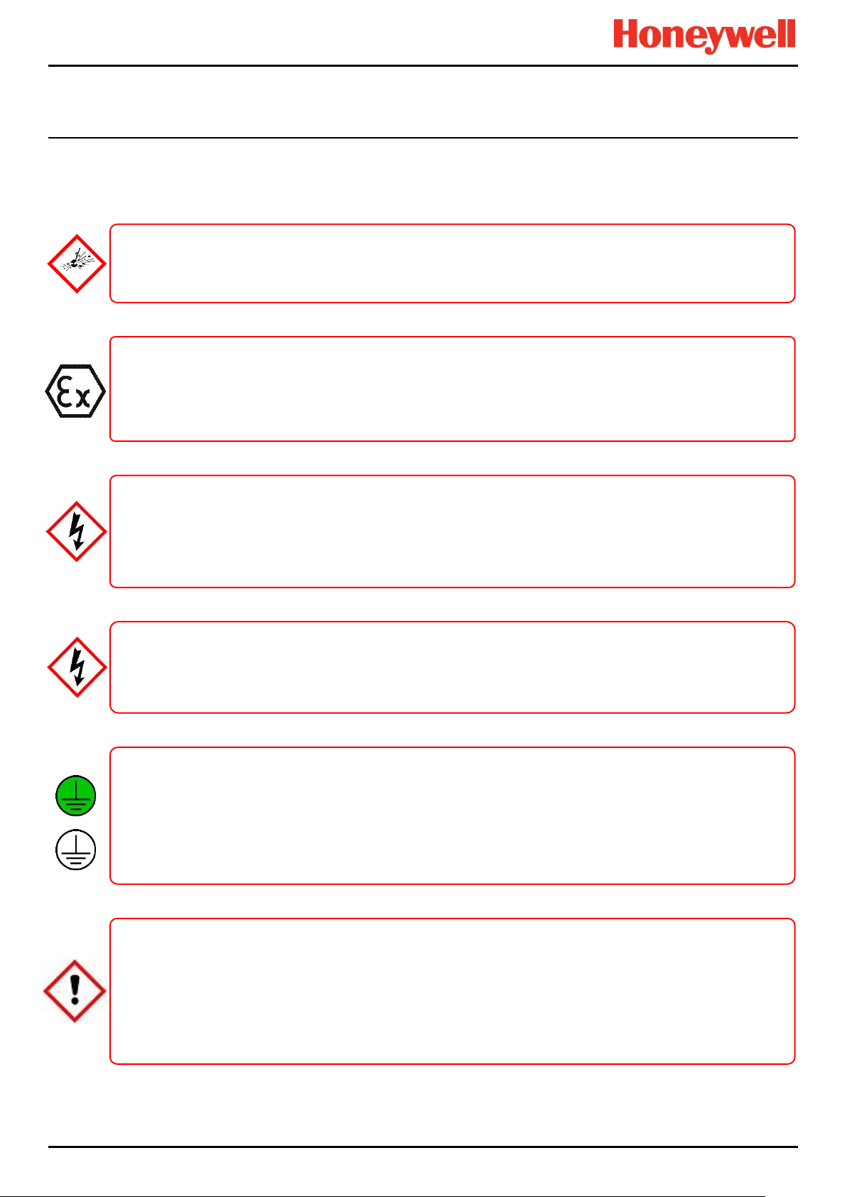
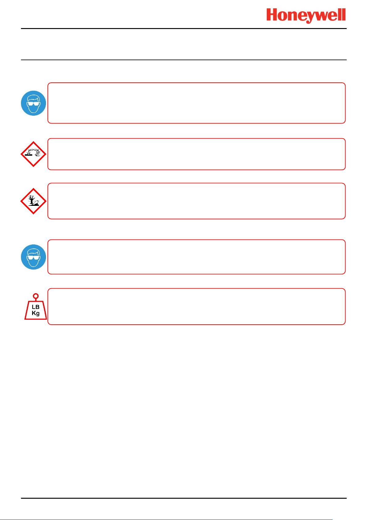
DANGER – IGNITION HAZARD
left.
WARNING – LETHAL VOLTAGE PRESENT
DANGER – IGNITION HAZARD
no flammable atmospheres, and no oxygen concentrations >25 % v/v O2.
WARNING – TOXIC WASTE AND HARMFUL BY-PRODUCTS
WARNING – LETHAL VOLTAGE PRESENT
Removable plug and socket connection is not permitted under any circumstance.
WARNING – LETHAL VOLTAGE PRESENT
discharged before touching live terminals.
2.1.2 Safety Hazards
The following specific hazards are associated with the use of this equipment:
The Touchpoint Pro Controller is NOT ATEX/IECEx safe, and it may only be installed in safe areas where there are
The Touchpoint Pro range includes a wall mounted enclosure that is certified as ATEX/IECEx Zone 2, Class I Div. 2
ATEX certified components may be used within the Touchpoint Pro and these bear the ATEX imprint shown to the
All power supplies must be hard wired and must include a circuit breaker (RCD / RCCB), and (close by and
unobstructed) a means of manually isolating and locking out the power supply without breaking the true earth
Lethal voltage may be present in this equipment when electrical power is applied. There is a danger of death or
injury from electrical shock. Isolate power before opening electrical access panels. Ensure residual current is fully
All installations, including cabinets, racks and remote units, must be connected to true earth, and must be capable of
Toxic waste and harmful by-products may accumulate within parts of the system. Suitable respiratory, eye and skin
protection should be worn when servicing these items. Stringent industrial hygiene precautions should also be
The Touchpoint Pro system and/or its sensors may become contaminated by the ambient environment in which it or
they are used. It is the Customer’s sole responsibility to ensure that all appropriate safety precautions are taken
and Class I (Zone 2) safe, but this enclosure can only be installed as a remote unit.
(ground) connection.
Lethal voltage may be present both internally and externally to the system.
staying earthed (grounded) when the power supply is interrupted.
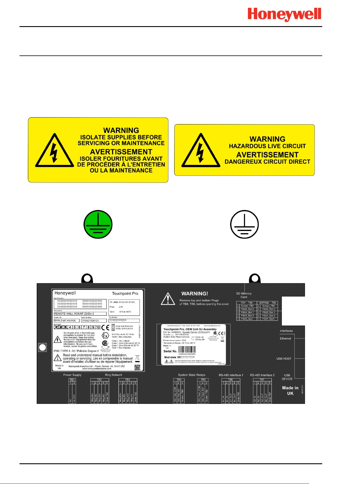
The Protective Earth (Ground) symbol is shown on the left, and it always has a green background.
Do not confuse it with the chassis earth symbol shown below it.
taken. Do not allow non-essential personnel into the work area.
before handling any components or transferring them to any other party.
Part. No. 2400M2501_6 Touchpoint Pro
6 Technical Handbook
Page 14
SAFETY
WARNING – EYE HAZARD
when clearing up chemical spills.
CAUTION – RISK OF PERMANENT EYE AND BODY DAMAGE
components.
CAUTION – CORROSIVE
hazard if improperly handled or carelessly disposed of.
CAUTION – RISK OF INJURY AND DAMAGE
CAUTION – HEALTH AND ENVIRONMENTAL HAZARDS
Safety Hazards (continued)
Contact your Honeywell authorised representative if you need further advice on any of the above.
The Touchpoint Pro system may contain sealed lead-acid batteries that may pose an eye hazard if the batteries
have become damaged or pressurised. Always wear suitable eye protection when handling the UPS or batteries, or
This equipment may contain batteries containing corrosive substances that may pose a health or environmental
This equipment contains a number of potentially toxic substances that may pose a health or environmental hazard if
exposed to very high temperatures, VOCs or corrosives, or if improperly handled or carelessly disposed of.
Always wear suitable eye protection and PPE when installing or removing the Touchpoint Pro system, or any of its
Touchpoint Pro enclosures are heavy and may become unstable when moved. Always wear PPE and ensure that
mechanical means and sufficient personnel are available to assist when moving or handling these items.
Part. No. 2400M2501_6 Touchpoint Pro
7 Technical Handbook
Page 15
SAFETY
Figure 1. Electrical Warning Label 1
Figure 2. Electrical Warning Label 2
Figure 3. Protective Earth (Ground) Point
Figure 4. Equipment Earth (Ground) Point
Note: Earth (Ground) Location Point labels are used inside the system and are not normally visible to the operator.
2.2 Location and Description of Warning Labels
2.2.1 Safety Warning Labels
Warning labels are mounted in specified locations on the equipment. This is to indicate conditions under which the user
could be subjected to electrical or other hazards.
See next page for further information.
Figure 5. Controller Rear Cover with Example Labels
Part. No. 2400M2501_6 Touchpoint Pro
8 Technical Handbook
Page 16
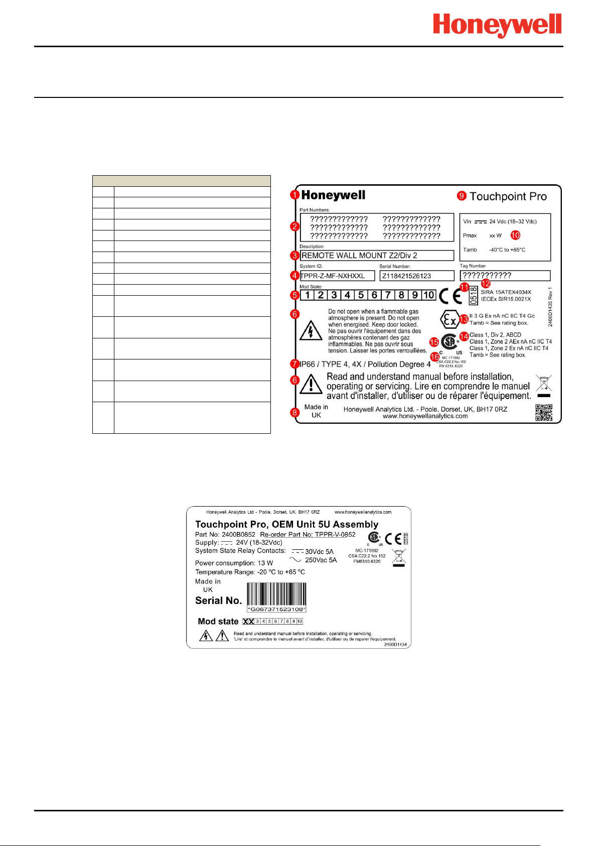
SAFETY
Key
1
Manufacturer
2
Part Numbers
3
Description
4
ID and Serial Number
5
Modification State
6
Safety Warnings
7
Ingress Ratings
8
Manufacturer Details
9
Equipment Title
10
Limits for Voltage / Power / T
amb
11
CE Mark and Notified Body for
Production Supervision
12
SIRA ATEX / IECEx Certificate
Numbers
13
ATEX / IECEx Hazardous Area
Certification Details
14
US/Canadian Hazardous Location
and Zone Certification Details
15
CSA Monogram Canada and USA
Certified
16
Manufacturer’s Master Contract
Number and Canadian / US
Performance Identification
2.2.2 Equipment Rating Labels (Hazardous Locations)
The following labels are fixed in prominent positions on the enclosure and on relevant modules. It is the user’s responsibility
to check individual rating plates before installation and to ensure that specifications are not exceeded during operation.
Exceeding the approved ratings invalidates product certification and the manufacturers’ warranties.
Some controllers may not have the label shown in Figure 6, but will have a label similar to the one in Figure 7.
Figure 6. Example of a Typical System Rating Label
Note: The CE mark and Notified Body number 0518 shown on product labels does not apply to Type ‘n’ approval.
Figure 7. Typical TPPR Product Label
Note: Similar labels appear on the Modules and the Backplanes.
Part. No. 2400M2501_6 Touchpoint Pro
9 Technical Handbook
Page 17
SAFETY
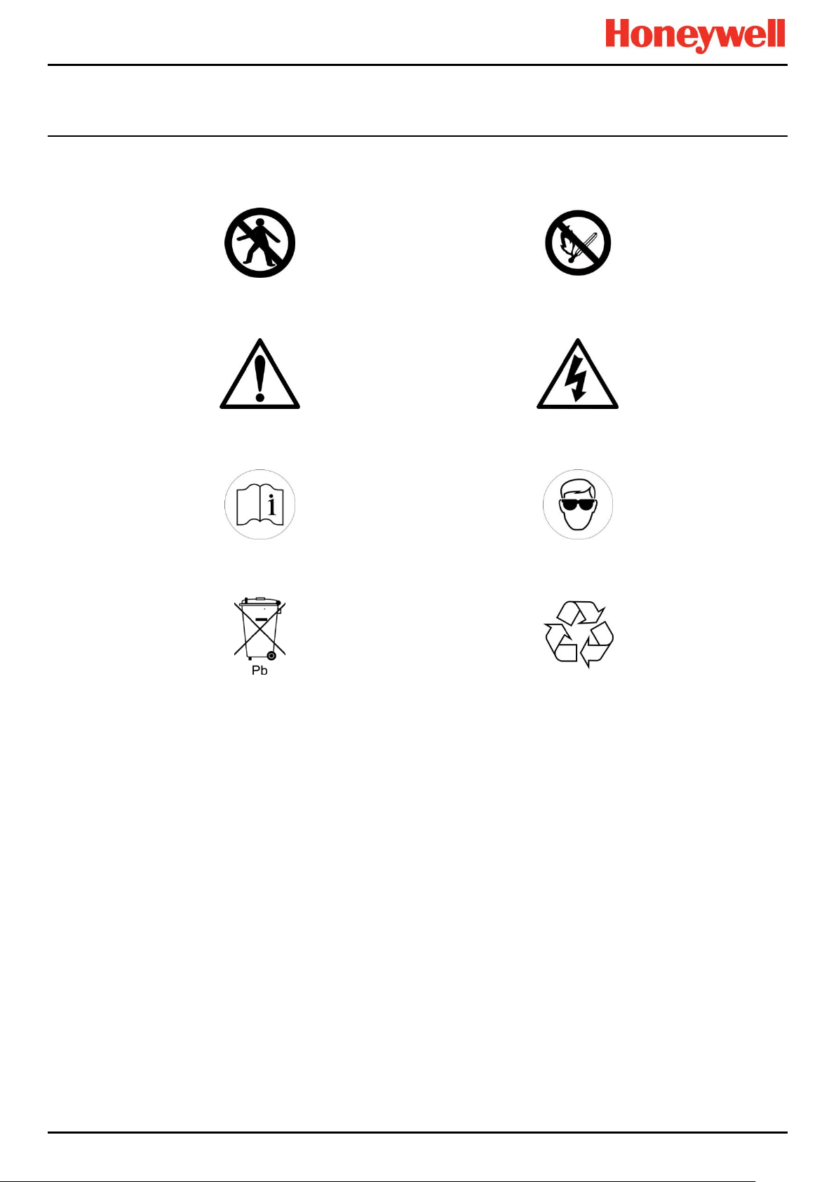
Figure 8. Keep Children Away
Figure 9. No Naked Flames
Figure 10. Use Caution
Figure 11. Electrical Hazard
Figure 12. Read The Instruction Manual
Figure 13. Wear Eye Protection
Figure 14. Hazardous Waste
(Pb = Lead)
Figure 15. Recycle Only
2.2.3 Warning Labels
The following symbols may be found on product labels and on the backup batteries:
Part. No. 2400M2501_6 Touchpoint Pro
10 Technical Handbook
Page 18

INTRODUCTION
Task
Administrator
Engineer
Operator
Basic System Setup
Change Language
Change My Password
Configuring Channels
Configuring Modules
Configuring System
Diagnostics
Help / User Guides
Licence Management
User Management
View and accept and
reset System Events
Generate Reports
3 Touchpoint Pro Introduction
Touchpoint Pro (TPPR) is a Command and Control System designed for the Honeywell Analytics’ (and third party) range of
fixed sensors and detectors. It provides constant sensor monitoring with automatic alarm response and notification. Its alarm
levels and responses are fully customisable and all events and errors are logged on a removable SD card for easy archiving.
TPPR is certified to monitor hazardous areas such as Zone 2 Div. 2 via remote Z2D2 enclosures.
TPPR can be used indoors or outdoors, in pollution degrees 2 to 4, and up to IP66, depending on the enclosure that is used.
In addition it can be securely networked and either controlled or monitored via a secure network connection and the
Honeywell PC Configuration software or via the secure Honeywell Webserver browser interface.
Note: Both access methods are optional licensed extras. Please visit the Honeywell website for further information or to
download the Operating Instructions.
3.1 TPPR Access Levels
The table below details the access levels for the Local User Interface (UI). Broadly speaking, an Administrator can
commission modules and configure channels, an Engineer can edit channel configuration and do calibrations and testing,
and an Operator can acknowledge and reset events during normal day-to-day operation. Other users can view current and
historical events and trend data, and generate reports.
TPPR is supplied with a default Administrator level account. For security reasons this password will be attached to the
system Touchscreen. When the system is configured, at least one new Administrator account should be created. The
default Administrator should then log out and then log back in as the new Administrator, and should then delete the
default Administrator account to prevent unauthorized access. The Administrator can create other users with
Administrator level access or lower and the Maintenance Engineer can create users with Engineer level access or lower.
Note: Forgotten or deleted passwords cannot be recovered so it is advisable to keep a copy of the master password in a
secure place or have two Administrator accounts.
Authorised users can carry out the following tasks:
Key: Yes , No Read only Engineer and Operator
Note: Only Administrators can end another user’s active session.
Note: For security reasons some of these tasks are unavailable through PC Configuration and Webserver software. Refer to
the appropriate User Manual for more information.
Note: TPPR’s ability to Accept and Reset events can be restricted to authorised users by changing the software settings.
However, remote switches cannot be restricted through software so alternative switch protection methods should be used
where required.
Part. No. 2400M2501_6 Touchpoint Pro
11 Technical Handbook
Table 1. TPPR Access Levels
Page 19
INTRODUCTION
Small Remote Unit
Controller Unit
Backplane
Controller
24 VDC Power Supply
(120/240/480 W)
Redundancy Module
(RDN)
Relay Output Modules
(ROM)
mV/mA Analogue Input Modules
(AIM)
Digital Input Modules
(DIM)
24 V DC-UPS
3.2 TPPR Control System Layout
The TPPR Control system can be built from just four main building blocks:
1. One Controller module with colour LCD touch screen User Interface
2. One backplane power and communications rail ( per enclosure or rack)
3. Power Supply modules (AC/DC, DC-UPS, Redundancy, Backup Battery)
4. Plug-in Input / Output (I/O) modules (mV, mA, AIM, DIM, ROM, Modbus)
Figure 16. TPPR Building Blocks
The illustration above shows wall mounted units but rack mounted and floor standing units use the same building blocks.
Enclosures can also hold multiple backplanes to allow for future system expansion.
Part. No. 2400M2501_6 Touchpoint Pro
12 Technical Handbook
Page 20

INTRODUCTION
Max. Loop 3 km
<1 km
<1 km
<1 km
<1 km
WARNING
appropriate barriers and armoured conduits, and that you follow all national and international cabling regulations.
3.2.1 Centralised Command and Control Option
TPPR can be installed as part of a centralised cabling system. With a centralised system, the field devices are individually
cabled back to the Controller and the field devices’ distance from the controller is limited only by the cable resistance and
whether or not power boosters are used.
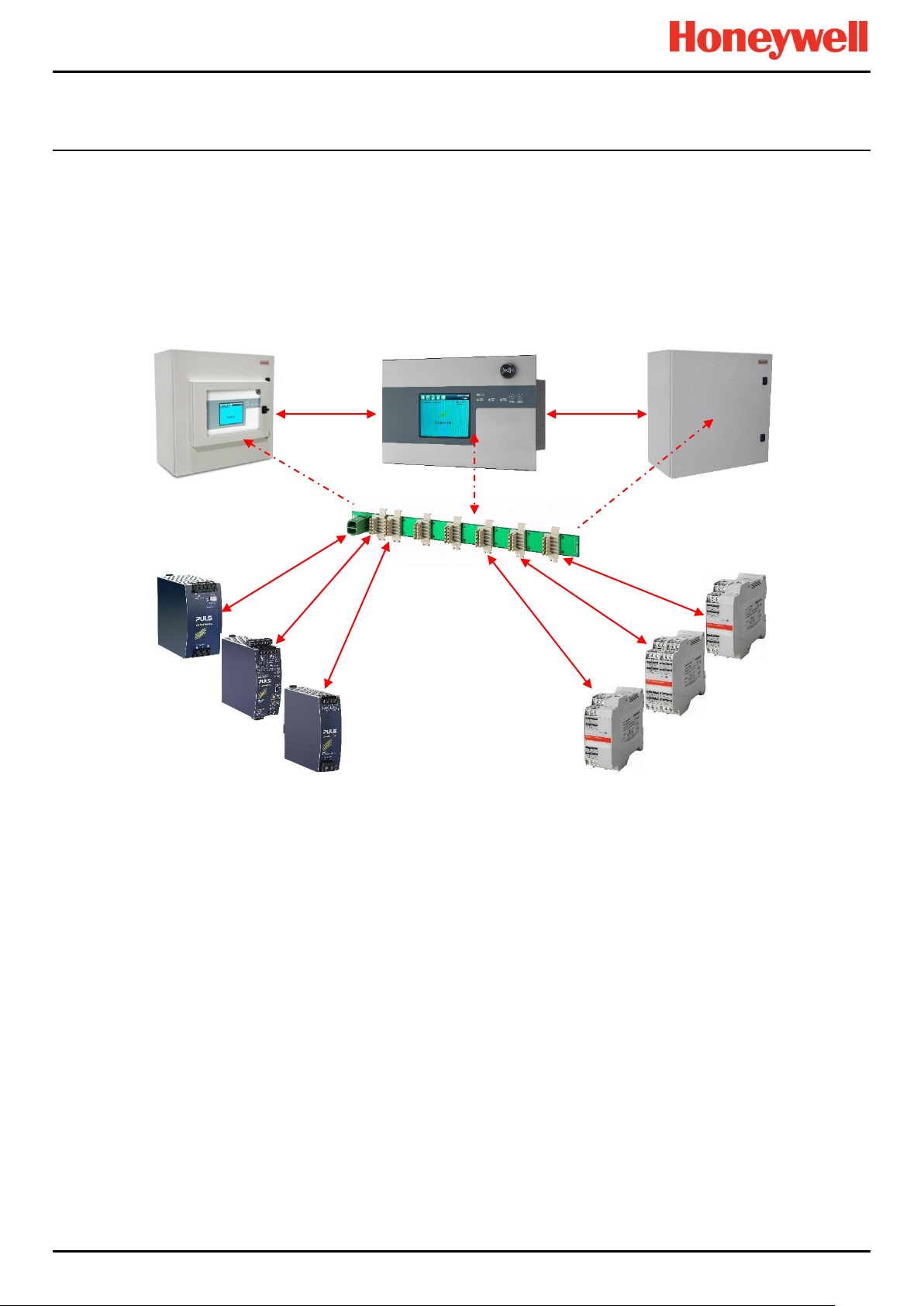
3.2.2 Distributed Command and Control (Remote Units) Option
TPPR can be installed as part of a distributed cabling system. In a distributed architecture, the field devices are connected
via short cable runs to TPPR Remote units, which are connected back to the controller by the Ring Network.
Remote units can be located up to 1 km (cable length) from the TPPR Controller or from each other, with a maximum cable
loop of 3 km for the complete system. The only connection required between the Controller and the Remote units is the
shielded network cable itself.
The TPPR Remote unit can be housed in any of the standard Enclosures, a 19” 5U rack, or a suitable 3rd-party enclosure. They do
not need a Controller but they do require their own power supplies.
Note: Standard Remote Units can be sited in safe areas to monitor and control devices sited in hazardous areas. You
should comply with all relevant legislation and you should follow the field device manufacturer’s installation and use
instructions.
The diagram below shows an example of a typical distributed setup showing both safe zone and zone 2 remote units.
You can install a Zone 2 Remote unit in Zone 2 to monitor sensors in ATEX Zone 1 provided that you use
Figure 17. TPPR Controller with Remote Units and Field Devices
Sensors
Actuators
Lamp Stack
Part. No. 2400M2501_6 Touchpoint Pro
13 Technical Handbook
Page 21
INTRODUCTION
3.3 TPPR System Key Components
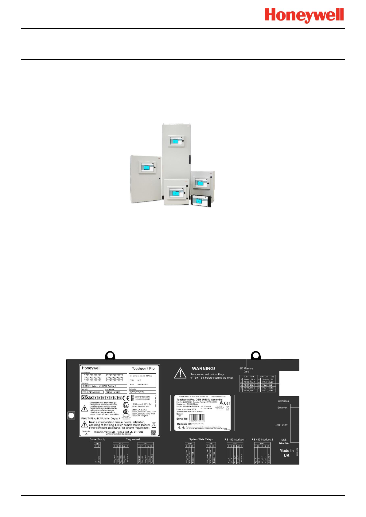
3.3.1 Enclosures and Racks
TPPR can be mounted in various sizes of floor or wall mounted enclosures, or on 19” 5U racks. The floor mounted
enclosures can be unventilated, naturally ventilated, or force ventilated. The fully sealed wall mounted enclosures can hold a
controller or can be a remote terminal without a controller.
If using a 19” rack, the OEM or installer must ensure the installation is at least IP20 / Type 1 / Class 1 (grounded) to mitigate
the risk of electrical shock.
Figure 18. TPPR Enclosures
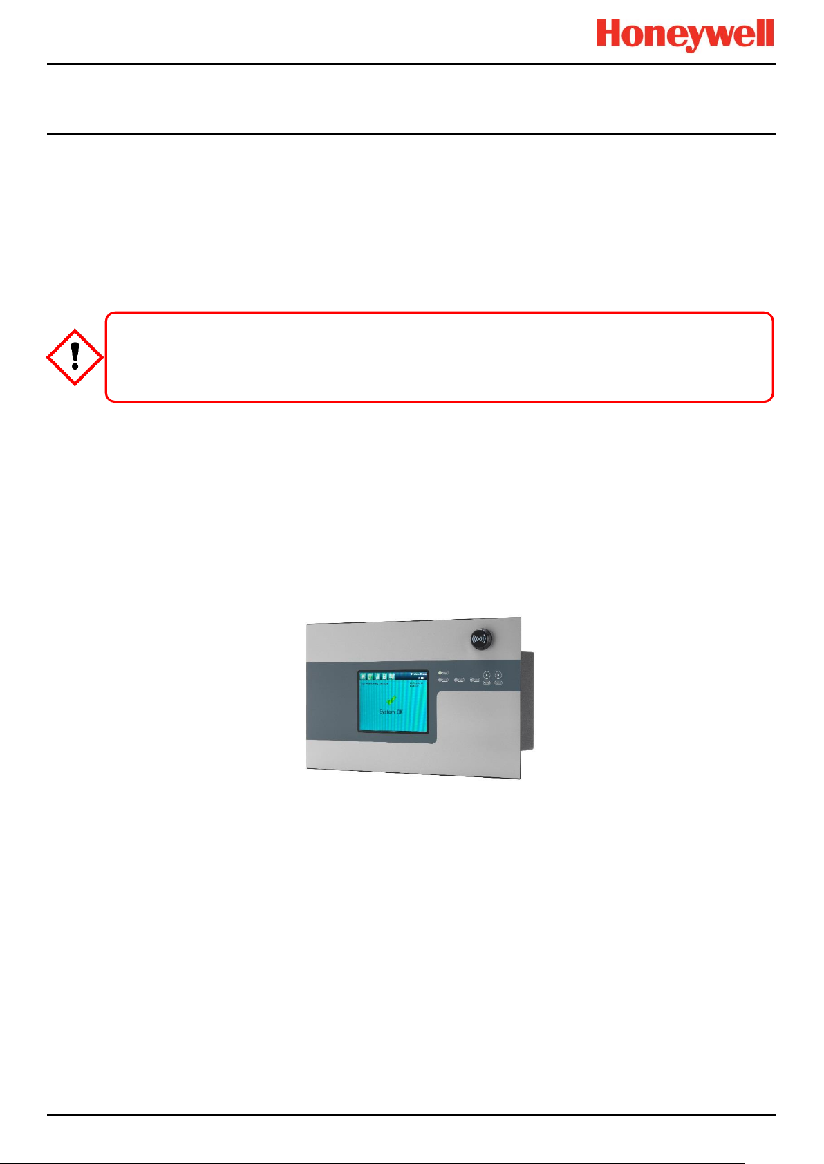
3.3.2 TPPR Controller User Interfaces
The TPPR Controller is covered with a protective membrane and houses the touch screen user interface (UI), the alarm
buzzer, the Accept and Reset buttons, and coloured LEDs for Power, Alarm, Fault, and Inhibit.
The controller has four access methods:
Control Panel touch screen for normal system operation, maintenance and configuration
PC Configuration Software (optional licences) for secure maintenance and configuration over a VPN or cable
Webserver (optional licences) allows up to 5 people to securely view events and carry out basic system operation via
an Ethernet connection or the Internet
Modbus option
Internal System Interfaces consist of:
Two master relays that signal System Failure and System Fault
Connections for one SD Card and one USB drive
10/100 Mbps Ethernet connection (for networked interfacing)
Optional dual RS 485 Modbus RTU interface
Figure 19. TPPR Controller Cover with Connection Map
Part. No. 2400M2501_6 Touchpoint Pro
14 Technical Handbook
Page 22
INTRODUCTION
CAUTION
3.3.3 SD Card
TPPR is supplied with an installed 4Gb SD card, which users may replace with a larger capacity if desired.
The SD card is used to store the event history of the system. TPPR logs all events and all changes to input readings.
Note: The SD Card should remain inserted during normal system operation as the motherboard has limited data storage
capacity.
3.3.4 USB Port
The USB Host port allows users to save reports, backup and restore configuration.
Note: USB devices must be formatted to FAT32 only; other file systems are not supported and will not work.
Note: The USB device is intended for maintenance and support operations only, and should be removed for normal use.
3.3.5 PC Configuration Software
This optional (downloadable) licensed software allows authorised users to configure some TPPR settings by using a remote
PC over an Ethernet connection. This is more efficient as you can use a larger screen and keyboard.
More information is available in a separate PC Configuration Operating Manual.
3.3.6 PC Operating Systems
Windows 7 is supported for use with PC Configuration software.
Honeywell will not be held liable for any loss or damage caused by any security breach, no matter how caused.
Windows XP is considered a high security risk and is not recommended.
3.3.7 Webserver Software
This optional (pre-installed) licensed software allows users to remotely view live status, and analyse event history.
Authorised users can also acknowledge, inhibit and reset I/O channels.
The Webserver supports up to 5 concurrent web clients. More than 5 clients can connect but performance may degrade.
More information is available in a separate Webserver Operating Manual.
3.3.7.1 Supported Web Browsers
TPPR software is compatible with most current web browsers.
Part. No. 2400M2501_6 Touchpoint Pro
15 Technical Handbook
Page 23
INTRODUCTION
CAUTION
3.3.8 Licences
The TPPR controller software does not require a licence.
Please contact your local Honeywell supplier or distributor to obtain licences for the optional PC Configuration and
Webserver options.
Refer to the PC Configuration or Webserver User Guides for details on installing and managing licences.
TPPR will notify you shortly before the expiry of your current PC Configuration or Webserver licence. Licence expiry does
not affect local operation using the local controller’s interface.
3.3.9 TPPR Controller Hardware
Internally the Controller houses the Control Centre Board (CCB) and the Communications Board (COB). It also contains an
SD Card slot, USB ports and an Ethernet / Printer port.
The CCB handles all functions related to the safety system operation, the Ring network, the LED indicators and buttons on
the front panel, and the master system state relays. An optional backup CCB is available for multiple redundancy
specifications.
The COB handles the remaining user interfaces – Touchscreen, SD, USB and the Ethernet and Modbus ports.
The Communication Board is completely independent from the Safety Function of the system.
Always follow the correct procedure to remove/suspend/reinstall a licence if your system software or firmware is
going to be updated or repaired. Full details are contained in the PC Configuration and Webserver User Manuals.
Figure 20. TPPR Controller
Part. No. 2400M2501_6 Touchpoint Pro
16 Technical Handbook
Page 24
INTRODUCTION
24 V DC
PSU Input
RCM
Sensor
Input Modules
Field Device
Output Modules
RCM Redundancy
Module (option)
Gas Detectors
TPPR- Activated Field Devices
Output Modules
Input Modules
Backplane
DIN Rail
Ring 'A'
Ring 'B'
Redundancy
Circuits
Communication Board
(COB)
Control Centre Board
(CCB)
TPPR Controller
PSU
RCM
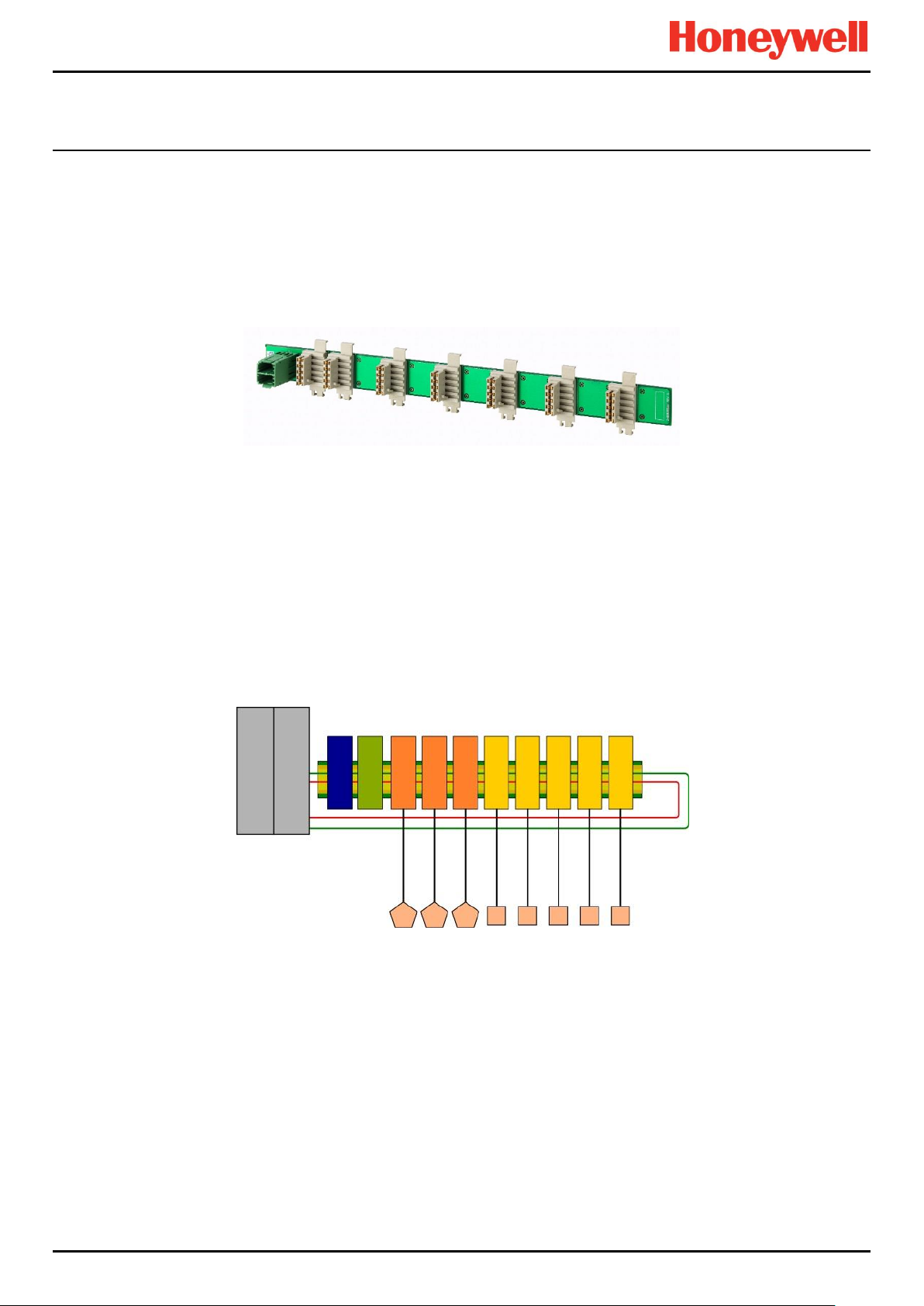
3.3.10 TPPR Backplane
The TPPR Backplane is the power and information highway to which all of the TPPR modules are attached. There can be
several backplanes in larger units, and they are installed within the DIN rail to which the modules are clipped.
The Backplane is available in four lengths (270 mm, 350 mm, 430 mm, 480 mm) to suit 5, 7, 9 or 10 I/O modules
respectively, but the choice may be restricted by the size of the selected power supply option and the need to maintain
adequate cooling space between modules.
Note: The DIN rail is 430 mm for a standard enclosure or 487 mm for the wide enclosure (10 x I/O) option.
Figure 21. TPPR Backplane
The Power Supply Unit (PSU) plugs into the green socket on the left hand side of the Backplane PCB, and it supplies power
to the modules via the white connectors. The Ring Coupling Module (RCM) normally sits next to the Power Connector and
handles all of the bi-directional communication between the CCB and the modules, again via the white connectors.
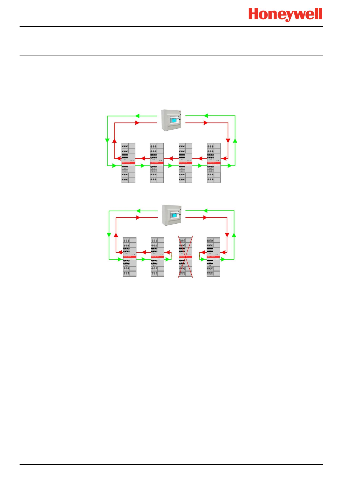
3.3.11 Ring Network
The Ring Coupling Module (RCM) and Input / Output (I/O) modules connect to a dual ring circuit so that they can
communicate with the CCB through each other and through the RCM.
This enables fail-safe redundancy because, if one addressable module fails and interrupts the primary circuit, the
addressable modules on either side of it can still communicate with the CCB via the backup ring circuit (see diagram below),
and the CCB can identify which module has failed by knowing which addressable modules are still active.
Figure 22. TPPR Controller Typical Schematic
Part. No. 2400M2501_6 Touchpoint Pro
17 Technical Handbook
Page 25
INTRODUCTION
For single cabinet installations, the Ring Network runs directly between the RCM and the Control Module.
For Remote units, the network runs additionally over data cable between the Controller and all of the backplanes in the
system.
The Ring Network is the only communication link required between the CCB and Remote Units (which have their own
backplanes, PSU and modules, but no Control Module).
Figure 23. Ring Circuit With All Modules Working
Figure 24. Ring Circuit With a Failed Module
Further information can be found in Ch.19 Ring Communication Errors.
Part. No. 2400M2501_6 Touchpoint Pro
18 Technical Handbook
Page 26
INTRODUCTION
Title
Description
Analogue Input Module 4–20 mA (AIM mA)
4-channel Analogue Input Module for 2 or 3 wire 4-20mA sensor signals
Analogue Input Module mV Bridge (AIM mV)
4-channel Module for mV-Bridge signals; supports up to 4 catalytic bead
flammable gas sensors
Digital Input Module (DIM)
4-channel Module for switched input devices such as manually operated
push buttons. Can also be used for remote access to alarm acknowledge,
reset and output inhibit inputs
Relay Output Module (ROM)
4-channel Module incorporating qty 4 SPCO (NO/NC) relays; suitable to
activate field mounted external alarms, actuators, drenching or shutter
systems, or to de-activate magnetic exit controls etc.
24 VDC Power Supply
(120/240/480 W)
Redundancy Module (RDN)
Relay Output Modules (ROM)
mV/mA Analogue Input Modules (AIM)
Digital Input Modules (DIM)
24 V DC-UPS
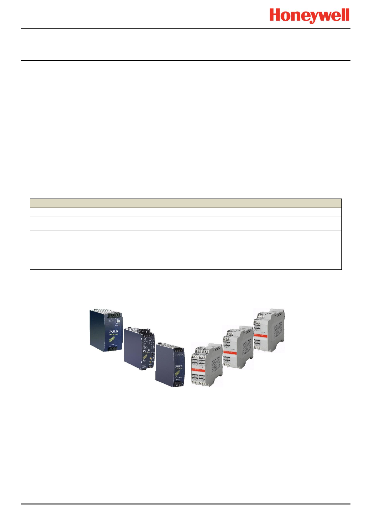
3.3.12 TPPR Modules
TPPR is of modular construction so it can be easily expanded if required. The quantity and mix of I/O modules is optional
and expandable.
Power Supply Unit (PSU) modules accept AC 120 – 240 V at 50/60 Hz single phase and are available in three power
outputs: 24 VDC @ 120, 240 or 480 W.
The optional DC-UPS is an uninterruptible DC power supply that links to and charges the optional 2 x 12 V Sealed
Lead Acid backup batteries.
The optional Redundancy Module (RDN) can control two DC 20A power inputs. If one input supply fails, the
Redundancy Module will switch over to the other, maintaining the DC output. Alarm relays will open if one of the input
supplies fails.
The Ring Coupling Module (RCM) enables fail-safe bi-directional (ring network) communication between modules and
the controller. An RCM is required for each backplane in the system.
Various types of I/O modules are available, each containing four channels. A single TPPR system can contain up to16 input
modules offering 64 input channels and up to 32 output modules offering 128 output channels.
Table 2. TPPR Module Types
Figure 25. TPPR Module Types
3.3.13 Sensor Catalogue
The TPPR Controller is pre-loaded with an updatable sensor catalogue that lists all of Honeywell Analytics’ current gas
sensors, each with a full default configuration setting that can be loaded when commissioning the Input modules. The full
configuration can be viewed afterwards, and individual parameters changed if desired.
The full procedure is explained in the Commissioning chapter.
Part. No. 2400M2501_6 Touchpoint Pro
19 Technical Handbook
Page 27
INTRODUCTION
AC Generator
Load
Circuit Breaker
Isolator
WARNING
AC power supplies must have a permanent connection to a protective earth, according to local regulations.
3.4 Power Supply Options
TPPR can be supplied from an AC 110/240 V Single Phase industrial supply via the optional Power Supply (PSU) Modules,
or from a direct DC 24 V power supply, or from optional 24 VDC backup batteries via the DC Uninterrupted Power Supply
module (DC-UPS).
When specifying power supplies, you should consider cabinet internal temperatures and cooling. In addition, power supplies
should be rated to allow for current surges and peaks. Contact your Honeywell representative for advice.
AC Mains
A full description of the available module types is given in the following sections.
Main Isolator
Battery
Figure 26. Typical Power Supply Setup
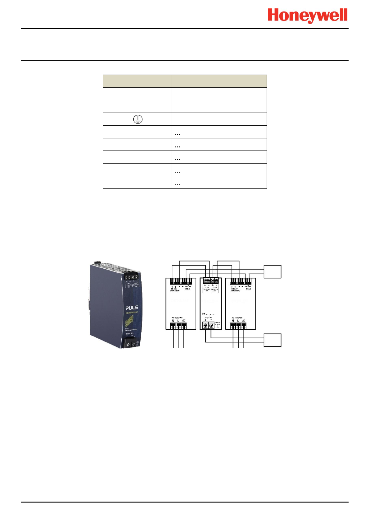
3.4.1 Power Supply Unit Modules (PSU)
The TPPR System can be equipped with PSU modules of different capacity, depending on the number of I/O modules being
used. The power supplies are mounted to the DIN-Rail and are available in the following ratings:
120/180 W, 24 – 28 VDC (5 A @ DC 24 V)
240/360 W, 24 – 28 VDC (10 A @ DC 24 V)
480/720 W, 24 – 28 VDC (20 A @ DC 24 V)
The power supplies have a 'DC Ok' status output that can be used to give a fault warning on failure.
Figure 27. Choice of PSU Size (120 W / 240 W / 480 W)
Part. No. 2400M2501_6 Touchpoint Pro
20 Technical Handbook
Page 28
INTRODUCTION
Terminal
Purpose
N
~ AC 110/240 V Neutral In
L
~ AC 110/240 V Line In
Protective Earth (Ground)
+
— DC 24 – 28 +V Output 1
+
— DC 24 – 28 +V Output 2
–
— DC –V Output 1
–
— DC –V Output 2
DC OK
— Relay Contacts 1 & 2
Failure
Monitor
20 A
Load
Table 3. PSU Terminal Allocation
3.4.2 Power Redundancy Module (RDN)
The RDN is an optional power supply backup system that can be installed with a second PSU to offer dual power supply
redundancy. Often the Mains supply will be connected to the first PSU and a stand-by generator connected to the second
PSU. The RDN will take power from either input and output it as a single source. See diagram below for cabling details.
Note: The RDN Output can also provide further redundancies via an optional battery backup and DC Uninterruptible Power
Supply (DC-UPS) module.
Figure 28. Power Redundancy Module Operation
Part. No. 2400M2501_6 Touchpoint Pro
21 Technical Handbook
Page 29
INTRODUCTION
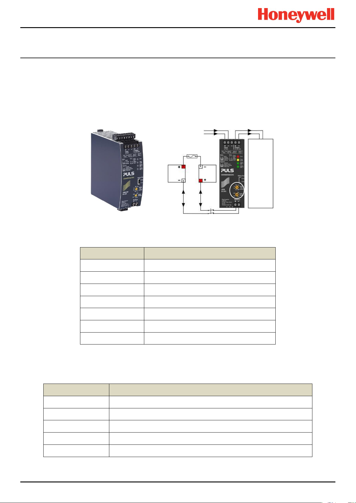
DC-UPS Terminal
Purpose
Input +
+24 VDC input from UPS
Input –
–24 VDC input from UPS
Input –
–24 VDC input from UPS (spare)
Output +
+24 VDC output to 20 A (max) Load
Output –
–24 VDC output to 20 A (max) Load
Battery +
+24 VDC Battery in/out
Battery –
+24 VDC Battery in/out
DC-UPS Terminal
Purpose
1 & 2
Ready relay: Closed when all is Ok (green)
3 & 4
Buffering relay: Closed when batteries are supplying power (yellow or buzzer)
5 & 6
Replace Battery relay: Closed when batteries fail load test (red or buzzer)
7 & 8
Do not use as Inhibit belongs to the Controller only
11 – 13
Not normally used
20 A
Isolator
Switch
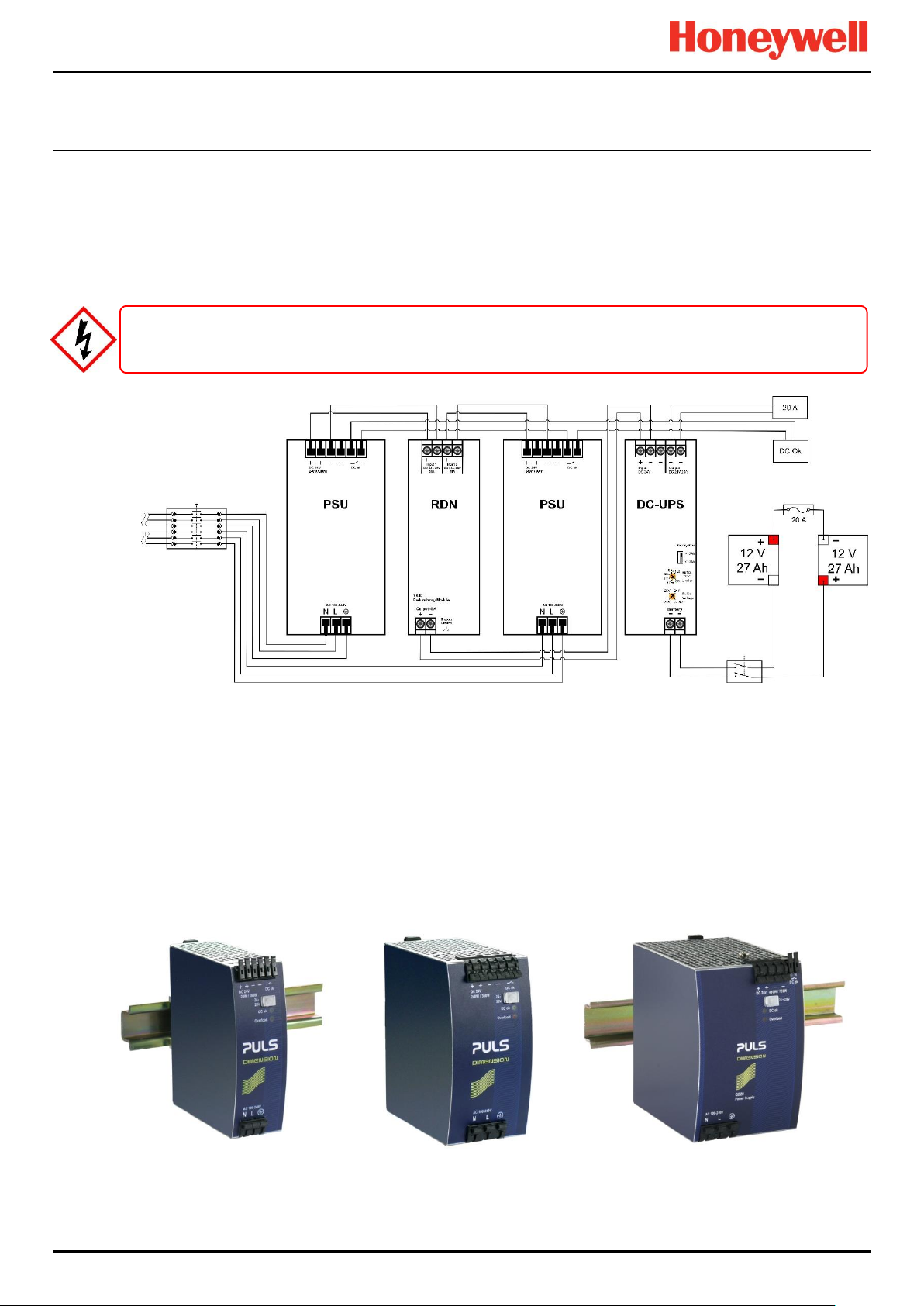
3.4.3 DC Uninterruptible Power Supply (DC-UPS) Module
The DC-UPS Module can be used with the separate and optional TPPR Battery Enclosure to provide continuous and
uninterrupted power to the TPPR in the event of an external power failure.
The DC-UPS is adjustable for buffer time and buffer voltage, and carries red, yellow and green status LEDs and descriptions
that show your backup battery status (see tables below).
Note: The DC-UPS Module Buffer Voltage should be set at 26 VDC to ensure optimum battery charging, and the Buffer-time
Limiter should usually be set to ∞ (see circled area on the figure below).
Figure 29. DC-UPS and Battery Configuration
The DC-UPS terminals are as follows:
12 VDC
Battery
24 VDC 24 VDC
12 VDC
Battery
20 A max
Load
Table 4. DC-UPS Primary Terminal Allocation
The DC-UPS also has Normally Open (NO) relay terminals that can be used for external repeaters such as a lamp stack or
alarm buzzer, as shown in the table below:
Table 5. DC-UPS Secondary Terminal Allocation
Part. No. 2400M2501_6 Touchpoint Pro
22 Technical Handbook
Page 30
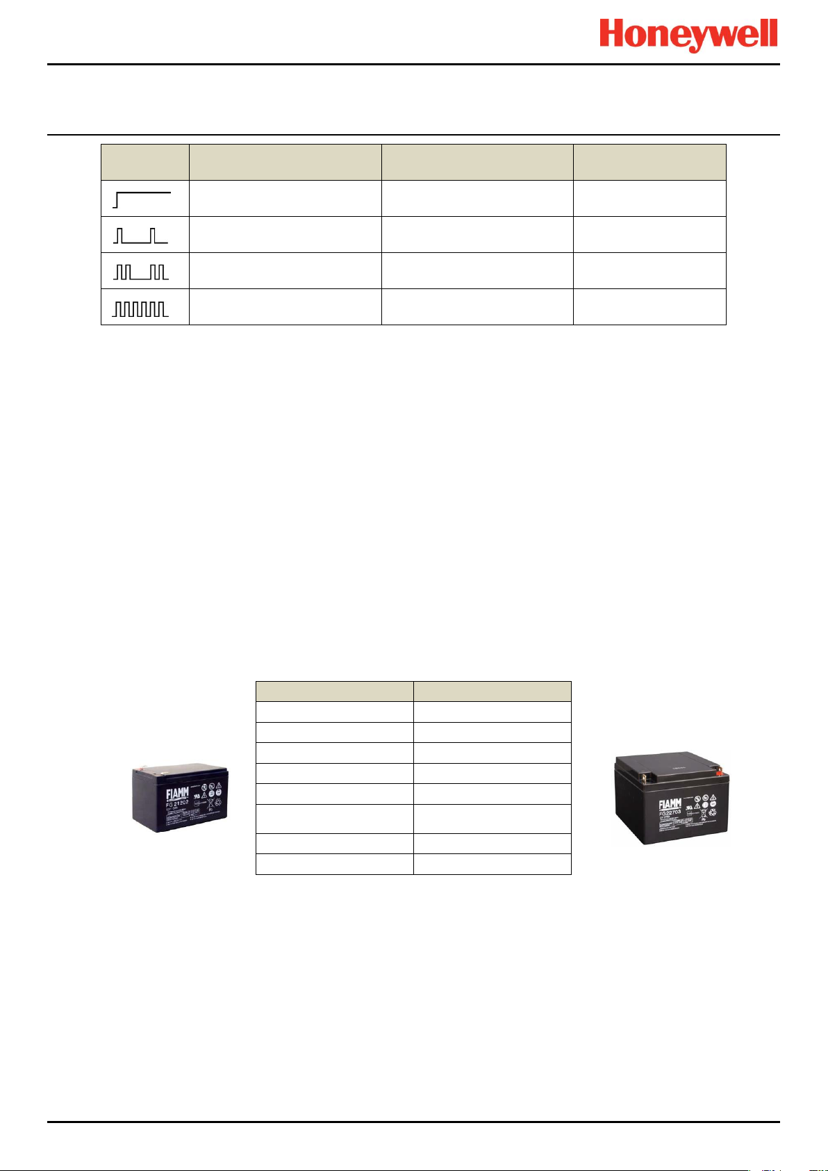
INTRODUCTION
LED Flash
Green Status LEDs
Yellow Diagnosis LED
Red Error LED
Steady means
DCUPS ready
Steady means
Power Overload
Steady means
Check the wiring
Single flash means
Charging
Single flash means
Replace Batteries
Single flash means
Check Input voltage
Double flash means
Refreshing
Double flash means
Buffer time expired
Double flash means
Over Temperature
Continuous flashing means
Buffering
Continuous flashing means
Inhibit Active
—
12 / 27 Ah Battery (pair)
Stand-by Use
Charge Voltage (max)
27 V
Input Current
3 A
Max Output Current
20 A
Max Load
30 A <4 Sec.
Fuse type (inline)
20 A Fast Acting Tube
Current Limit Protection
20 A Double-pole Circuit
Breaker / Isolator,
Weight 12 Ah
3.75 kg (ea.)
Weight 27 Ah
8.5 kg (ea.)
Table 6. DC-UPS LED Meanings
3.4.4 Backup Batteries
The optional Battery Enclosure contains two rechargeable 12 V batteries wired in series to give a nominal 24 VDC supply.
The batteries can be either 12 Ah or 27 Ah and they are overload-protected by a 20 A fast acting inline cartridge fuse.
A new set of 12 / 27 Ah batteries should supply 22.5 V at 20 A for up to 16.75 / 32 minutes respectively, depending on the
connected load. However, you should be aware that all batteries deteriorate over time, and Honeywell recommend that you
check and replace them regularly to ensure optimum performance in an emergency.
Note: Always switch the Battery Isolator switch to Off before carrying out any work on the battery circuit, and ensure it is On
when work is completed.
The 12V monobloc batteries are Valve-Regulated Lead Acid (VRLA) Absorbed Glass Mat (AGM) batteries that:
Are optimized for discharge (buffer) times of up to 20 hours @ 3 A.
Have a 5 year design life in float operation in temperature controlled environments.
Have VRLA AGM and gas recombination technology with 99% internal recombination.
Are non-spillable and maintenance free.
Are non-hazardous when packaged for air/sea/rail/road transportation.
Are 100% recyclable.
Table 7. Backup Battery Details
Part. No. 2400M2501_6 Touchpoint Pro
23 Technical Handbook
Page 31

INTRODUCTION
20 A
Isolator
Switch
24 VDC 24 VDC
12 VDC
Battery
12 VDC
Battery
20 A max
Load
Figure 30. Battery Circuit
Part. No. 2400M2501_6 Touchpoint Pro
24 Technical Handbook
Page 32

MECHANICAL INSTALLATION
4 TPPR Mechanical Installation
Mechanical installation consists of physically mounting the TPPR Enclosure on a wall or, for floor mounted enclosures, on a
suitable plinth, and then fixing cable trays in appropriate locations. Electrical Installation is covered in the next chapter.
4.1 TPPR Siting Considerations
TPPR can be installed in a wide range of wall floor and rack mounted enclosures but you should always consider the
following when choosing locations:
TPPR is specified for operation in ambient temperatures from -20°C to +55°C (TPPR Controller) or -40°C to +65°C
(no Controller). However the upper ambient temperature may be reduced dependent on the type and quantity of
installed components. It is the user’s responsibility to check the equipment rating plates for the true ambient range of
the installation as operation outside of this temperature range invalidates the warranty and certification.
All enclosures and racks have individual Ingress Protection and type ratings. It is the user’s responsibility to check
individual rating plates for requirements.
Only Zone 2 Div. 2 and Remote enclosures can be installed outside in unprotected locations. See Ch.20 TPPR
Specifications for further details.
TPPR enclosures shall be protected from direct sunlight where exposure could cause the unit temperature to rise
beyond the specified operating limits, or where UV light could damage the Controller's membrane or Touch screen. It
is the installer’s responsibility to ensure that the unit temperature does not rise beyond the specified operating limits.
The TPPR wall mounted enclosure shall be installed only on a vertical surface and floor mounted enclosures shall be
installed only on a suitable weight-bearing plinth. Use the mounting fixtures supplied with the apparatus plus any
specialist fixtures determined by the location, and follow the installation instructions carefully.
The mounting surface should be flat, and strong enough to bear the weight of the TPPR system. Solid brick type
construction is recommended, while drywall / plasterboard, dry lined or timber framed type construction is not
considered to be a suitable structural material unless appropriately reinforced. Take account of the contents and
external cabling in addition to the weight of the wall mounted enclosure itself (check maximum enclosure weights detailed in
the next section).
There must be sufficient clearance to mount the wall mounted enclosure and be able to fully open the door. A
minimum clearance of 100 mm all round plus space for cable entries is required. The door hinge is on the left side.
Beware of proximity to entries, exits and sloping ceilings.
If more than one enclosure is to be used, ensure that there is sufficient clearance between the enclosures for cable
glands, mounting, cooling, door opening etc. This applies especially when mounting the backup battery
enclosure beneath the TPPR Controller Enclosure.
Ensure that the TPPR interface and touch screen can be freely viewed and reached. A wall enclosure touch screen
height of approximately 1.5 m is recommended for comfort, but the height of a floor mounted enclosure will be
determined by the enclosure size and height of the plinth.
Beware of siting TPPR in vehicle movement areas as personal injury may result. Erect safety barriers if this is
unavoidable.
TPPR conforms to the requirements of European and other standards for EMC and RFI. It should not be installed in
close proximity to the antennae of high power radio, radar and satellite communication equipment, or in the vicinity of
high voltage switching gear or overhead power lines.
All signal cables should be shielded and bonded to protect them from stray or induced current.
Part. No. 2400M2501_6 Touchpoint Pro
25 Technical Handbook
Page 33

MECHANICAL INSTALLATION
Description
Approximate
Weight in kg
600 x 600 x 300 mm powder coated steel enclosure with Controller
41
600 x 600 x 300 mm powder coated steel enclosure no Controller
37
800 x 600 x 300 mm powder coated steel enclosure with Controller
50
800 x 600 x 300 mm powder coated steel enclosure no Controller
46
1200 x 800 x 300 mm powder coated steel enclosure with Controller
85
380 x 300 x 210 mm Backup Battery Enclosure (empty)
8
12 Ah Battery (pair)
7.5
27 Ah Battery (pair)
17
CAUTION
Refer to local safety regulations.
CAUTION
Wall mount and plinth fixing bolts should be a minimum 8 mm dia. x 50 mm depth.
×
4.2 Installing Wall Mounted Enclosures
The TPPR Controller and Remote units can be installed in a wide range of wall mounted enclosures.
The TPPR wall mounting brackets must always be installed in a vertical orientation as shown below.
Touchpoint Pro enclosures are heavy and unwieldy (refer to Specifications) and a single person lift is not
recommended. Before lifting the enclosure, consider and implement control measures to reduce the risk of injury.
It is the installer’s responsibility to select the appropriate fixings while taking into account the structure of the
mounting surface and the weight of the specific enclosure.
Figure 31. TPPR Correct Enclosure Mounting Orientation
4.2.1 Wall Mounted Enclosure Weights
The following table shows approximate weights for various wall mounted enclosures, but this should only be viewed as an
example as the exact enclosure weight depends on the custom configuration of Controller and modules. System weights will
be given on the shipping note.
Table 8. Approximate Wall Mounted Enclosure Weights
Part. No. 2400M2501_6 Touchpoint Pro
26 Technical Handbook
Page 34

MECHANICAL INSTALLATION
4.2.2 Wall Mounted Enclosure Dimensions
The dimensions of the various wall mounted units (Controller or Remote) are shown below (all dimensions in mm):
Figure 32. Small Wall Mounted Enclosure
Figure 33. Medium Wall Mounted Enclosure
Figure 34. Large Wall Mounted Enclosure
Part. No. 2400M2501_6 Touchpoint Pro
27 Technical Handbook
Page 35

MECHANICAL INSTALLATION
CAUTION
Refer to local safety regulations.
CAUTION
mounting surface and the weight of the specific enclosure.
CAUTION
Wall and plinth fixing bolts should be a minimum 8 mm dia. x 50 mm depth.
CAUTION
The following unit is certified for use in hazardous areas/locations ATEX/IECEx II 3G Ex nA IIC T4 Gc or CSA Zone 2, Class
I Div. 2, and Class I (Zone 2). This enclosure can only be used as a remote unit as no controller option is available.
Figure 35. Hazardous Area Wall Mounted Enclosure
4.3 Installing Floor Standing Enclosures
The TPPR Controller can be mounted in a range of large powder coated steel floor mounted enclosures, either fully
enclosed or with or additional natural or forced ventilation.
All enclosures are approximately 2000 x 800 x 600 mm (without ventilation hood and lifting lugs)) and weigh >230 kg. See
the shipping note for accurate details.
Note: Optional air vents can be fitted to front or rear doors depending on whether front or rear cable access is used.
Users shall not allow the ventilation to become blocked or subjected to moisture ingress as this will void certification
and the warranty, and may cause irreparable damage.
Touchpoint Pro enclosures are heavy and unwieldy (refer to Specifications) and a single person lift is not
recommended. Before lifting the enclosure, consider and implement control measures to reduce the risk of injury.
It is the installer’s responsibility to select the appropriate fixings while taking into account the structure of the
Due to their size and weight, floor mounted enclosures must stand on a minimum 100 mm thick purpose built plinth,
and must be securely fixed to either the plinth or wall.
Part. No. 2400M2501_6 Touchpoint Pro
28 Technical Handbook
Page 36

MECHANICAL INSTALLATION
Front
Rear
Side
4.3.1 Floor Standing Enclosure Dimensions
Figure 36. Example of a Floor Mounted System with Forced Rear Ventilation and Vent Hood
4.4 Installing the TPPR 19". Rack Mounted Unit
This module is designed to fit into an industry standard 19" rack, with a height of 5U. The dimensions of the 19" rack
mounted unit (Controller or Remote version) are shown below (all dimensions in mm).
Note: It is the OEM and Installer's responsibility to ensure that the unit is electrically and environmentally safe and is
protected against the ingress of dust or moisture.
4.4.1 TPPR 19” Rack Mounted Unit Dimensions
Figure 37. TPPR 19" Rack Dimensions
Part. No. 2400M2501_6 Touchpoint Pro
29 Technical Handbook
Page 37

MECHANICAL INSTALLATION
4.5 Installing the TPPR Panel Mount Controller
This module is designed to be fitted into a custom panel. It has a height of 5U and a bezel mounting kit is available. The
dimensions of the unit are given below (all dimensions in mm), and the panel cut-out hole should be (w x h) 368 x 232 mm.
Note: It is the OEM and Installer's responsibility to ensure that the unit is electrically and environmentally safe and is
protected against the ingress of dust or moisture.
4.5.1 TPPR Panel Mount Controller Dimensions
Figure 38. TPPR Panel Mount Dimensions
4.5.2 TPPR Controller Mounting Bezel Option
There is an optional bezel mounting unit available when mounting the Controller in a custom enclosure.
Note: The bezel mounting nuts must be tightened in the correct order and to the correct torque settings. Incorrect tightening
will result in distortion of the front panel membrane so refer to the documentation supplied with the mounting kit, or contact
Honeywell for advice.
Figure 39. TPPR Bezel Mounting Kit
Part. No. 2400M2501_6 Touchpoint Pro
30 Technical Handbook
Page 38

MECHANICAL INSTALLATION
CAUTION
(CSA-C22.2 No 61010, ANSI/ISA 61010-1(82.02.01)), i.e. an environment such as an office or control room.
CAUTION
outside of this range invalidates the warranty and certification.
CAUTION
and that there will be sufficient room to fit or remove the batteries when required.
CAUTION
within 3 months of delivery.
CAUTION
CAUTION
4.6 Installing the Battery Enclosure
Battery Enclosure installation is described in a logical sequence starting with assembling and mounting the optional battery
enclosure followed by assembling and fitting the batteries.
Batteries are classified as hazardous goods and must be shipped in their own packaging. It is therefore necessary for the
customer to install the batteries into the enclosure after the enclosure is securely mounted.
Note:
Prior to starting mechanical installation, it is recommended that you take into account that the DCUPS to Battery
Enclosure Circuit Breaker / Isolator cable is limited to a maximum of 5 m of 4 mm2 cable, and that you position the
enclosures accordingly before making any permanent fixings.
The TPPR Battery Enclosure must be installed in a Pollution Degree 2 environment as defined by IEC 61010-1
The TPPR Battery Enclosure is specified for operation in ambient temperatures from -20°C to +45°C. Operation
Ensure that there will be unobstructed access to the Circuit Breaker / Battery Isolator switch inside the enclosure,
The backup batteries have a limited shelf life, so please ensure that the batteries are connected and fully charged
Fix the battery enclosure securely to the wall before installing the 7.5 kg (12 Ah x 2) or 17 kg (27 Ah x 2) batteries.
The TPPR Battery Enclosure should be installed only on a vertical surface and avoiding sloping surfaces. Only use
the mounting brackets supplied with the enclosure, and carefully follow the installation instructions below.
The mounting surface should be flat, and strong enough to bear the weight of the Enclosure with the batteries
installed. Drywall / plasterboard, dry lined or timber framed type construction is not considered to be a suitable
structural material, unless strengthened with additional supports or braces and/or special fixings. Take into account
the weight of the batteries and external cabling in addition to the weight of the unit itself.
The TPPR Battery Enclosure should have a clearance of 200 mm to either side, and there should be no heat sources
below or adjacent to it. Do not obstruct the air vents on either side.
Part. No. 2400M2501_6 Touchpoint Pro
31 Technical Handbook
Page 39

MECHANICAL INSTALLATION
1
4.6.1 Assembling and Mounting the Battery Enclosure
The dimensions of the TPPR Battery enclosure and mounting points are shown below.
Figure 40. TPPR Battery Enclosure Dimensions
1. Insert the mounting brackets (1) into their mounting points. Fit the M6 bolts and torque to 6 Nm.
2. Identify the required cable entry point. Remove the cable gland plate and drill out the hole required for the cable
entry. Support the cable gland plate to avoid distortion.
3. Fit the cable gland to the cable entry. The cable gland should be appropriate to the application and capable of
maintaining the IP20 rating. The cable gland must provide anchorage and stress relief for the incoming cables.
4. Re-fit the cable gland plate.
5. Select a suitable mounting position for the enclosure, taking into account the siting considerations above.
6. Mark and drill four holes corresponding to the mounting hole positions.
7. Secure the Battery enclosure in place. The mounting holes are 10 mm in diameter. Fixing bolts should be a
minimum diameter of 8 mm, and to a minimum depth of 50 mm.
8. Feed the TPPR DC-UPS battery supply cables through the gland and insert them into the enclosure Isolator / Circuit
Breaker terminals.
9. Tighten the cable gland to prevent ingress of moisture.
10. Ensuring that both TPPR mains power and battery isolator are Off, connect the battery supply cables to the DCUPS.
Note: It is the installer’s responsibility to select the appropriate fixings while taking into account the structure of the mounting
surface and the weight of the enclosure plus batteries i.e. circa 15.5 kg (12 Ah x 2) or 25 kg (27 Ah x 2).
Part. No. 2400M2501_6 Touchpoint Pro
32 Technical Handbook
Page 40

MODBUS INSTALLATION
WARNING
CAUTION
WARNING
Removable plug and socket connection should not be used under any circumstance.
5 TPPR Electrical Installation
5.1 Power Requirements
Installation must be in accordance with the recognized standards of the appropriate authority in the country
concerned. Refer to local, national and company regulations.
TPPR power supplies are supplied already wired. Do not modify any factory fitted cabling.
All power supplies must be hard wired and must include a suitable circuit breaker (RCD / RCCB), and (close by and
unobstructed) a means of manually isolating and locking out the power supply without breaking the protective earth
(ground) connection.
5.1.1 Power Consumption
The power consumption of your system was calculated when it was ordered. See the supplied Certificate of Conformity, or
the fixed rating plate for details.
5.1.2 AC Power Input
AC Power input (if used) must be single phase AC 100 – 240 V, 50/60 Hz.
The mains supply requires an overcurrent protection rated in accordance with the rating plate on the specific system. The
supply must be a fixed installation, i.e. not plug and socket.
The supply must be able to be isolated by means of a lockable switch or circuit breaker, which must be suitably located,
easily reached and clearly marked as the TPPR disconnect device.
The wiring used between the isolator and TPPR must be appropriately rated and approved.
5.1.3 DC Power Input (excluding backup batteries)
External DC Power input (if used) must conform to the Input Supply Voltage given in Ch.20 TPPR Specifications, and it must
not be located inside the TPPR wall mounted enclosure.
The voltage supply requires an overcurrent protection rated in accordance with the rating plate on the specific system.
The supply must be able to be isolated by means of a lockable switch or circuit breaker, which must be suitably located,
easily reached and clearly marked as the TPPR disconnect device.
The wiring used between the isolator and TPPR must be appropriately rated and approved.
Ensure that the power supply is able to maintain sufficient voltage level for the connected field devices and to recharge the
backup batteries.
External DC supplies would normally connect directly to the DC-UPS input terminals, but other connection methods may be
used.
Part. No. 2400M2501_6 Touchpoint Pro
33 Technical Handbook
Page 41

MODBUS INSTALLATION
WARNING
Electrical Code (CEC).
WARNING
All cabling must be appropriately rated and approved in accordance with local, national and international regulations.
This is particularly important when reusing existing or legacy cables.
5.1.4 DC Power Output
The TPPR DC power output can be set to between 24 and 28 VDC (the default is 24 V).
TPPR power supply units (PSU) include a DC Ok relay that closes when the output voltage reaches the adjusted output
voltage level, and opens when the output voltage dips more than 10% below the adjusted output voltage level.
The DC Ok Relay has a maximum rating of 60 VDC 0.3 A, 30 VDC 1 A or 30 VAC 0.5 A resistive load and a minimum
permissible load of 1 mA at 5 VDC.
Note: If the battery backup option is being used, ensure that the PSU DC output and the DC-UPS Module buffer voltages
are set to >24 V to ensure optimum battery charging for 2 x 12 V batteries.
Note: If the Power Redundancy Module is being used, ensure that both PSUs have the same output voltage.
5.2 Cabling Requirements
All cabling should meet local, national and international regulations, and be suitable for the operating environment. Cable
should be appropriately rated and approved. Bootlace ferrules should be used on all stranded cable end terminations unless
otherwise stipulated (e.g. where the backup batteries use spade terminals).
Additionally, cabling must satisfy requirements defined in the technical manuals of connected field devices,
especially when the field device is certified for use in hazardous locations.
In Canada and the USA, in both ordinary and hazardous locations, all electrical installations, including connections,
cabling and overcurrent protection must strictly adhere to both the National Electrical Code (NEC) and the Canadian
5.2.1 Device Cables
Field device cabling should be appropriate to the area classification, and in accordance with the device manufacturer’s
recommendations. Refer to local and national regulations where appropriate, and the field device manual. All sensor field
cables must be shielded and grounded to ensure correct operation of the system and to meet European Standards for RFI
and EMC.
Ensure that the maximum loop resistance is not exceeded, as specified by the device manufacturer.
Take account of voltage drops due to line resistance to ensure that the correct voltage level is present at the field device, as
specified by the device manufacturer.
The I/O modules will accept wire sizes up to 2.5 mm² / AWG 11.
5.2.2 External Power Supply Cables
Use approved supply cables rated in accordance with the rating plate on the specific system, in accordance with local and
national regulations. The TPPR power supplies will accept wire sizes in the range 0.5 – 6 mm² / AWG 25 – 3 (solid wire), 0.5
– 4 mm² / AWG 25 – 7 (stranded wire).
5.2.3 Bus Interface Cables
Modbus cables should use a good quality signal cable suitable for RS485 connections. See Ch.6.5 Modbus Cables for
further information.
Part. No. 2400M2501_6 Touchpoint Pro
34 Technical Handbook
Page 42

MODBUS INSTALLATION
Max. 3 km Loop
<1 km
<1 km
<1 km
<1 km
TPPR Remote
TPPR Remote
TPPR Remote
TPPR Controller
5.2.4 Ethernet Cables
Ethernet cable must be CAT5e or CAT6 Ethernet cable terminated to TIA/EIA-568B standard. The cable should have
shielded RJ45 plugs with the shield of the cable bonded to the metal body (shield) of the connector plug. The cable length
should not exceed 100 m. The Ethernet cable should be fitted through a gland to preserve the IP rating where appropriate.
5.2.5 TPPR Battery Box Cables
Connect the TPPR Battery enclosure to protective earth using a minimum wire size of 6 mm2 (10 AWG) and the M8
Protective Earth (ground) stud.
The cable between the TPPR System UPS and the TPPR Battery Box must be 4 mm² / AWG 7; UL/CSA approved wiring
material, tri-rated (105 °C). The maximum cable length between the Battery Box and the UPS is 5 m. Bootlace ferrules must
be used on all stranded cable end terminations except for the battery-end spade terminals (supplied).
5.2.6 24 VDC Power Cables
24 VDC power cables should be rated appropriate to the current load.
The Modules will accept a maximum wire size of 1.5 mm² / AWG 15 and the DIN rail connector will accept a maximum wire
size of 6 mm² / AWG 3.
5.2.7 Ring Network Cables
Ring network wiring should use good quality signal cabling suitable for RS485 signals.
The external ring network cabling should be shielded and grounded twisted pair cables. The terminals will accept a
maximum wire size of 1.5 mm² / AWG 15.
5.2.8 Ring Network Cable Restrictions
The TPPR total ring network cabling must not exceed 3 km (1.86 miles). The distance between individual TPPR units (i.e.
between a Controller and a Remote Unit) must not exceed 1 km (0.62 miles).
Figure 41. Ring Network Maximum Distances
Part. No. 2400M2501_6 Touchpoint Pro
35 Technical Handbook
Page 43

MODBUS INSTALLATION
Armour
Shielding
Shielding
Protective Earth
Junction Box
Sensor
TPPR
Shielding
Protective Earth
Junction Box
Sensor
TPPR
WARNING
Avoid creating earth (ground) loops.
5.2.9 Earthing (Grounding)
All TPPR equipment, sensors and cable shielding shall be earthed (grounded) using only the dedicated TPPR earth
All cable armour and/or metal conduits shall be separately earthed and isolated from the TPPR, its equipment and
5.2.10 Location of the Primary TPPR Protective Earth (Ground) Connection Stud
The primary TPPR protective earth (protective ground) stud is marked with a green earth (ground) label, and can be found:
Standard enclosures – lower left corner
Rack mount units – reverse side, lower left corner
Instrument and common earth (ground) points are marked with a black and white earth label.
5.2.11 Cable Shielding (Screening)
Field device cable shielding shall be connected to instrument earth (ground) at the respective TPPR controller or remote unit
only, and the opposite end shall be isolated from contact with any metal body or cable.
Factory supplied enclosures contain a pre-fitted bus bar for earthing the field cables and it is recommended that OEMs fit
them in their custom TPPR enclosures / racks.
The diagrams below show some examples of acceptable TPPR earthing and shielding practice.
Figure 42. Shielding with Metal Armour, Metal Junction Box and Metal Sensor Body
Figure 43. Shielding with no Armour, Metal Junction Box and Metal Sensor Body
terminals or common earth rail. Do not disturb or remove factory-fitted earth connections.
its attached cables.
Part. No. 2400M2501_6 Touchpoint Pro
36 Technical Handbook
Page 44

MODBUS INSTALLATION
Armour
Shielding
Shielding
Junction Box
Sensor
TPPR
Protective Earth
Shielding
Protective Earth
Junction Box
Sensor
TPPR
Figure 44. Shielding with Metal Armour, Plastic Junction Box and Plastic Sensor Body
Figure 45. Shielding with no armour, Plastic Junction Box and Plastic Sensor Body
Note:
Cable shielding (screening) shall be connected to the TPPR enclosure’s common earth point only, and both shall be fully
isolated from all other metal bodies.
Cable armour and/or steel conduit and/or metal junction boxes and/or metal sensor bodies must be connected to protective
earth (ground) in the field and shall be kept fully isolated from contact with cable shielding (screening) and from contact with
TPPR enclosures or metal enclosure glands.
Long cable runs should be earthed in the field at regular intervals but be careful to avoid earth (ground) loops.
Part. No. 2400M2501_6 Touchpoint Pro
37 Technical Handbook
Page 45

MODBUS INSTALLATION
CAUTION
5.2.12 Assembling and Installing the Backup Batteries
Identify all required parts as follows:
Two batteries – 12 Ah (small) or 27 Ah (large)
One positive cable, one negative cable and one cable with bayonet style fuse holder
Fitting kit of spade terminals, nuts, bolts and washers (used with 27 Ah batteries only)
Avoid shorting the battery terminals with metal or conductive objects, especially when connecting the cables or when
For the large batteries only, fit a supplied spade terminal to each battery terminal using the supplied fixings. The correct
sequence for the fixings is – bolt, flat washer, battery terminal, spade terminal, flat washer, spring washer, nut, as shown
below.
Note: Ensure that the terminals are positioned vertically and angled inwards or the cables will not fit.
The 12 Ah batteries fit into the offset mounting tray slots with the terminals to the front, while the 27 Ah batteries may require
you to first remove the 12 Ah mounting tray (3 screws at the front and 2 at the back) before fitting the batteries with the
terminals facing each other. Always fit the right hand battery first to avoid blocking access.
Normally the door opens to the left and the 27 Ah batteries are therefore positioned to the far right to avoid contact with the
door hinge. However the door hinge can be changed to open to the right, in which case the 27 Ah batteries must be
positioned to the far left instead.
It is advisable to remove the fuse before connecting the fused cable to the batteries, and to refit it only when all
Figure 46. 27 Ah Battery Terminal Assembly
1. Ensure that the Battery Isolator switch is correctly connected to the TPPR DC-UPS and is switched Off (Fig 48).
2. Ensure that the securing strap is open and held clear of the battery area.
3. Insert the first battery in the right-hand slot (12 Ah) or far right (27Ah).
4. Insert the second battery to the left of the first battery, observing the correct terminal orientation (see pictures
below).
Figure 47. Correct Battery Orientation
installing the batteries in the enclosure.
cables are correctly connected and tested.
Part. No. 2400M2501_6 Touchpoint Pro
38 Technical Handbook
Page 46

MODBUS INSTALLATION
Isolator
Isolator
WARNING
5. Fasten the securing strap over the batteries.
6. Optional; smear the battery terminals lightly with grease or petroleum jelly to prevent electrolytic corrosion.
7. Using the supplied cables, connect the batteries to the Battery Isolator switch (see picture below). Ensure that the
protective boots cover the terminals.
8. Connect the supplied cable and fuse assembly between the two remaining battery terminals, red to positive, black to
negative.
9. Check that the fuse is fitted and the bayonet holder is fully closed.
10. Switch the Battery Isolator On and ensure that the TPPR DC-UPS LED shows the correct battery status (requires
TPPR to be connected to a power source and switched on).
11. Close and lock the access door and allow the batteries to recharge.
12. Check the DC-UPS periodically for battery status updates; carry out any necessary rectification or maintenance.
Figure 48. Battery Connections
Unauthorised modification of the Touchpoint Pro system or components is forbidden as it will invalidate certification
and may render the system dangerous or inoperable.
Battery
Battery
5.2.13 Connecting Devices to Modules
It is not necessary to populate all (or any) of the channels, nor in any particular order. In some cases you may have empty
modules waiting for future system upgrades.
See the following sections for wiring and circuit plans and verify all connections before switching on TPPR power.
Note: The lower terminals (inputs 3 and 4) are inverted when compared to the top terminals (inputs 1 and 2) so it is not
electrically possible to swap cable plugs from top to bottom or vice-versa.
Part. No. 2400M2501_6 Touchpoint Pro
39 Technical Handbook
Page 47

MODBUS INSTALLATION
Channel
Terminal
Label
Field Device
Input 1
1
+V
24 VDC
2
SIG
4 – 20 mA Signal
3
–V
0 VDC
Input 2
4
+V
24 VDC
5
SIG
4 – 20 mA Signal
6
–V
0 VDC
Input 3
7
+V
24 VDC
8
SIG
4 – 20 mA Signal
9
–V
0 VDC
Input 4
10
+V
24 VDC
11
SIG
4 – 20 mA Signal
12
–V
0 VDC
Device
TPPR
5.2.14 Connecting to an Analogue Input Module (4 – 20 mA)
The Analogue Input Module mA (AIM mA) is a sink module that accepts 4-20 mA source signals from 2-wire or 3-wire field
devices. The sensors connect via the front-face terminals.
The module can supply 18-32 VDC (24 VDC nominal) to the field devices at a maximum current of 1 A per channel, with the
additional limitation that the total current drawn from the module must not exceed 2 A at 65 °C ambient or 4 A at 55 °C
ambient.
Voltage outputs are overload protected.
Table 9. AIM mA Connection Table
The following diagrams show how to connect various types of device or sensor.
Figure 49. Three Wire Device
Part. No. 2400M2501_6 Touchpoint Pro
40 Technical Handbook
Page 48

MODBUS INSTALLATION
Device
TPPR
Device
TPPR
Barrier
Device
TPPR
Barrier
Figure 50. Two Wire Loop Powered Device
Figure 51. Two Wire Device with a Barrier
Note: Refer to the device manufacturer’s instructions for details of approved barriers and connections for Intrinsically Safe
(I.S.) field devices.
Figure 52. Two Wire Device with Alternative Barrier
Part. No. 2400M2501_6 Touchpoint Pro
41 Technical Handbook
Page 49

MODBUS INSTALLATION
Channel
Terminal
Label
Field Device
Input 1
1
S
Sensitive (+)
2
01
Signal 3 NS
Non-sensitive (–)
Input 2
4
S
Sensitive (+)
5
01
Signal 6 NS
Non-sensitive (–)
Input 3
7
S
Sensitive (+)
8
01
Signal 9 NS
Non-sensitive (–)
Input 4
10
S
Sensitive (+)
11
01
Signal
12
NS
Non-sensitive (–)
Device
TPPR
Barrier
Device
TPPR
Figure 53. Two Wire Device with an Isolated Barrier
5.2.15 Connecting to an Analogue Input Module mV Bridge
The Analogue Input Module mV Bridge (AIM mV) accepts Catalytic (180 mA to 360 mA reactive bead) type sensors
connected via the module’s front-face terminals.
Bead current is programmable in the range 180mA to 360mA (default 200mA). Bead current may be independently set for
each channel.
Part. No. 2400M2501_6 Touchpoint Pro
42 Technical Handbook
Table 10. AIM mV Connection Table
Figure 54. mV Bridge Catalytic Detector
Page 50

MODBUS INSTALLATION
Channel
Terminal
Label
Input 1
1
+
2
3
–
Input 2
4
+
5
6
–
Input 3
7
+
8
9
–
Input 4
10
+
11
12
–
Figure 55. Unsupervised Circuit
Figure 56. Supervised for Open Circuit
TPPR
TPPR
TPPR
5.2.16 Connecting to a Digital Input Module
The Digital Input Module (DIM) has two modes of operation. A DIM channel may be configured to generate an alarm, fault or
warning signal when activated.
Alternatively, a DIM channel may be configured to provide remote control of a selected group of one or more input / output
channels. The DIM may be used to remotely reset, inhibit, or acknowledge the selected channels.
When used for inhibit, repeated activation toggles the inhibit state of the selected channels.
Note: It is the user's responsibility to guard against unauthorised inputs when using remote switches, buttons or keys.
Table 11. IM Connection Table
Figure 57. Supervised for Open and Short Circuit
Part. No. 2400M2501_6 Touchpoint Pro
43 Technical Handbook
Page 51

MODBUS INSTALLATION
Channel
Terminal
Label
Channel
Terminal
Label
Relay 1
1
NO
V Aux 1
13 2
NC
14 + 3 C 15
–
Relay 2
4
NO
V Aux 2
16 5
NC
17 + 6 C 18
–
Relay 3
7
NO
V Aux 3
19 8
NC
20 + 9 C 21
–
Relay 4
10
NO
V Aux 4
22 11
NC
23 + 12 C 24
–
5.2.17 Connecting to a Relay Output Module
The Relay Output Module (ROM) provides relay outputs to switch field devices such as sounders, beacons and actuators. In
addition, an auxiliary voltage supply is available to provide power to such devices.
The relay contacts have a recommended range of ≥12 VDC, 10 mA to 250 VAC / 30 VDC 5A. The maximum contact current
rating is 5 A per channel, with the additional limitation that the maximum contact current rating for the module is 8 A. An
overcurrent protection device should be fitted to prevent higher current flowing through the relay contacts.
The auxiliary voltage supply provides DC 24 V (18–32 VDC) to the field devices at 1.5 A max. per channel, with the
additional limitation that the total current drawn from the module must not exceed 1.5 A. The supply is short circuit protected
– if a short circuit is detected the supply to all four channels is disconnected to prevent damage. The auxiliary voltage supply
will be restored automatically when the cause of the short circuit is removed.
Table 12. ROM Connection Table (Unpowered)
Figure 58. ROM Connections
Part. No. 2400M2501_6 Touchpoint Pro
44 Technical Handbook
Page 52

MODBUS INSTALLATION
Input
Terminal
Label
Channel
Input 1
1 + Ring A In
2
Drain
3 –
Input 2
4
+
Ring B Out
5
Drain
6 –
Input 3
7 + Ring B In
8
Drain
9 –
Input 4
10
+
Ring A Out
11
Drain
12 –
5.3 Controller Electrical Connections
Controller electrical connections are detailed on the Controller cover (shown below).
Figure 59. Controller’s Terminal Layout Map
5.3.1 Communications Ring Wiring
The ring wiring connects from TB2 and TB3 on the controller to one or more Ring Coupling Modules (RCMs), depending on
the system configuration. The RCMs may be fitted in the same cabinet as the controller, in a remote cabinet up to 1km
away, or a combination.
5.3.1.1 Ring Coupling Module (RCM) Connections
Each backplane requires an RCM. The RCM is normally positioned in the leftmost position on the backplane.
Table 13. RCM Connection Table
Note: Terminal 2 is connected to Terminal 5 and Terminal 8 is connected to Terminal 11.
The Drain terminals are capacitively coupled to power supply 0V.
Refer also to section Ring Coupling Module (RCM)21.4.3 for RCM specifications.
Part. No. 2400M2501_6 Touchpoint Pro
45 Technical Handbook
Page 53

MODBUS INSTALLATION
1
Ao +
Ao -
2
3
Bi +
Bi -
4
1
Bo +
Bo -
2
3
Ai +
4
TB2
1
Ain +
Ain -
3
4
Bo +
Bo -
6
7
Bi +
Bi -
9
10
Ao +
Ao -
12
TB3
5
11
Ai -
8
DRN
DRN
2
5
5
BackplaneController RCM
1
Ao +
Ao -
3
Bi +
Bi -
4
1
Bo +
Bo -
2
3
Ai +
4
TB2
TB3
Controller
Ai -
2
1
Ain +
Ain -
3
4
Bo +
Bo -
6
7
Bi +
Bi -
9
10
Ao +
Ao -
12
5
11
RCM 1
8
2
1
Ain +
Ain -
3
4
Bo +
Bo -
6
7
Bi +
Bi -
9
10
Ao +
Ao -
12
5
11
RCM 2
8
Backplane
2
Backplane
The following diagrams show typical ring wiring. For clarity, screens are omitted.
Figure 60. Ring Network Connections
Part. No. 2400M2501_6 Touchpoint Pro
46 Technical Handbook
Figure 61. Ring Network – Dual Backplane
Page 54

MODBUS INSTALLATION
Requirement
Value
Cable size
Minimum
1mm²
Loop Resistance
Maximum
26 ohms/km
Mutual capacitance conductor to conductor
Maximum
125 pF/m
Mutual capacitance conductor to shield
Maximum
160 pF/m
Inductance conductor to shield
Maximum
0.65 mH/km
RCMController
1
3
4
2
TB2
5
Pin 2 or 5
1
3
4
2
TB3
5
Pins 8, 11
Local Remote
DRN
DRN
5.3.1.2 Screen Connections
It is the installer’s responsibility to provide suitable connections for ring cable screens.
The Drain (DRN) connections at the controller and at the RCM should be connected. They are capacitively coupled to the
controller/backplane 24V return (0V) line, and isolated to DC.
Connections to earth or chassis must be made externally.
5.3.1.3 Earth Clamp
The ring cable screen should be connected to chassis using a suitable clamp. To avoid ground loops, each screen should
only be grounded at one end.
5.3.1.4 Multiple RCMs
Screens between multiple RCMs may be connected using the RCM DRN connections on pin 2/5 and 8/11. Each leg should
be provided with a separate single earth connection.
5.3.1.5 Communications Ring Cabling
The communications ring uses RS485 signalling.
The external ring network cabling should use 2x2 twisted pair cables with overall screen. The cable used should take into
account the location, environment and distance but must be a good quality signal cable suitable for RS485 signals and
meeting the following requirements:
Figure 62. Representative Screen Connections
Table 14. Communications Ring Cable
For ease of wiring and commissioning, different wiring colours should be used for A and B rings. The terminals will accept a
maximum wire size of 1.5 mm² / AWG 15.
Part. No. 2400M2501_6 Touchpoint Pro
47 Technical Handbook
Page 55

MODBUS INSTALLATION
System Failure Relay (TB4)
Terminal
System Fault Relay (TB5)
Terminal
SIS_Fail_COM
1
SIS_Fault_COM
1
SIS_Fail_NO
2
SIS_Fault_NO
2
Screen_TB4
3
Screen_TB5
3
Digital Input TB8
Terminal
Digital Input TB9
Terminal
PSU1_Stat 1
1
PSU3_Stat 1
6
PSU1_Stat 2
2
PSU3_Stat 2
7
PSU2_Stat 1
3
PSU4_Stat 1
8
PSU2_Stat 2
4
PSU4_Stat 2
9
Screen_TB8
5
Screen_TB9
10
TPPR
CAUTION
5.3.2 TPPR Controller' System State Relays
The System State Relay connections are located on the Controller at TB4 and TB5 (See Figure 56). They are rated at 30
VDC (3 Amp) or 250 VAC (3 Amp).
An overcurrent protection device should be used if the System State Relays are being used to switch AC voltages.
5.3.3 Power Supply Unit (PSU) Status Inputs
Table 15. System State Relay Connections
The Power Supply Unit (PSU) Status Input connections are located on the Controller at TB8 and TB9 (see Figure 59).
Four digital inputs are provided on TB8 and TB9. The inputs are provided for PSU status monitoring or ventilation
monitoring. Refer to section 13.16 for further information.
They may be used as general purpose digital inputs if not required for this specialist monitoring.
These inputs can be configured to act as Global Acknowledge, Global Reset or Global Inhibit.
5.3.4 RS485 (Modbus) Interface 1 & 2 Connections
See Ch.6 Modbus Installation for details on installing and connecting to the optional Modbus PCB.
The RS485 Interface functions on TB6 and TB7 are described in the Modbus section. Refer to Chapter 11
Part. No. 2400M2501_6 Touchpoint Pro
48 Technical Handbook
Table 16. PSU Input Connections
Figure 63. PSU Status Circuit
Page 56

MODBUS INSTALLATION
5.4 First Time Switch On
Before applying power to TPPR, ensure that all wiring and connections are correct and that all glands are tightened.
Switch on the battery isolator switch (if DC-UPS is fitted) and then the main isolator switch.
During the start-up, verify that the front panel LEDs illuminate in sequence and that the buzzer sounds. Verify that the LCD
functions correctly.
During TPPR start-up check that the DC supply voltage is between 18 and 32 VDC at the Vaux terminals of a Relay Output
Module (preferably furthest from the power source) or at the V+ and V- terminals of an Analogue Input Module.
TPPR initialisation typically lasts for 3 – 10 minutes depending on the number of channels and sensors in the system.
TPPR will then display the System Status screen, indicating the current status of the system.
Note: AIM-mV Bridge channels will be in Inhibit mode until calibrated. In addition, some mA or mV channels may have a
‘power-up’ delay programmed, which means that those channels could remain inhibited until the end of the delay, i.e. up to
5-mins.
The TPPR Controller System Status Screen is shown below.
Figure 64. System Status Screen
Part. No. 2400M2501_6 Touchpoint Pro
49 Technical Handbook
Page 57

MODBUS INSTALLATION
CAUTION
6 Modbus Installation (Option)
6.1 Introduction
The optional TPPR Modbus Interface provides a facility for digital communication between the TPPR and an external
computer system. Modbus is a well-supported digital data communication protocol that provides a standardised set of data
communication protocols.
The principal features of the Modbus Interface are:
Operates as a Modbus Remote Terminal Unit (RTU) slave device node.
Supports functions 02, 03, 04, 06 and 16 of the Modbus protocol.
Provides sensor gas readings and alarm status for Fault, Inhibit, Warning, A1, A2, A3, STEL, LTEL and Rate alarms
from all input channels in the system.
Supports commands to Inhibit, Reset and Acknowledge for all channels in the system, as well as Global Reset and
Global Acknowledge.
Dual RS485 half-duplex communication with multi-drop capability.
Asynchronous serial link configurable for baud rate and parity.
Maintenance Note: The Modbus broadcast commands are not supported and will be ignored.
6.2 Programming the Host
The host computer system must be programmed to interpret the signal and status data from TPPR as there is no defined
standard Modbus format for the communication of data from gas detection systems.
It is recommended that the host computer system should, as a minimum, be programmed to use Function 02 to collect alarm
and status data from all TPPR channels.
Full details of the Modbus protocol can be found in the Modicon Modbus Protocol Reference Guide PI-MBUS-300 available
from www.modbus.org.
Some transceiver manufacturers incorrectly use RS-485 pin A as data positive and pin B as data negative. You may
have to swap over TDA and TDB (A in and B in) if your Modbus does not work as expected.
6.3 Addressing Conventions and Register Values
The addressing conventions and register values used follow those set by Modicon. The first digit of the on-board memory
address refers to the data type stored in the register and therefore defines the Modbus function command that should be
used when polling it.
1xxxx – The Input Status Register addresses record the individual channels’ status. They are read using Modbus Function
02.
3xxxx – The Input Register addresses record the current input values of the individual channels. They are read using
Modbus Function 04.
4xxxx – The Holding Register addresses have two purposes. One range of addresses is used to send commands and
receive the results of those commands. The other address range is used to send queries and store the results of those
queries. They can be written singly using Modbus Function 06, written as a block using Modbus Function 16 and read using
Modbus Function 03.
Part. No. 2400M2501_6 Touchpoint Pro
50 Technical Handbook
Page 58

MODBUS INSTALLATION
WARNING
WARNING
CAUTION
CAUTION – ELECTROSTATIC HAZARDS
WARNING
WARNING
Relay Output Modules even if the TPPR is electrically isolated.
6.4 Modbus Bus Interface Board (BIB) Installation
The optional Modbus Bus Interface Board (BIB) is required to use Modbus communications. Normally the BIB is factory
installed, but it can be fitted or replaced in the field by an authorised Honeywell Field Engineer.
TPPR is supplied with Modbus software pre-installed.
6.4.1 How to Install the Bus Interface Board
To fit the Bus Interface Board:
Part. No. 2400M2501_6 Touchpoint Pro
51 Technical Handbook
The equipment specified in this manual is only to be installed by the Manufacturer’s trained personnel, or by
competent persons trained in accordance with the Manufacturer’s installation instructions.
There is a risk of electric shock when carrying out this procedure. Ensure that the system and backup batteries are
electrically isolated and that residual power is allowed to dissipate before opening the enclosure.
If the TPPR relays are switching mains voltages, hazardous live terminals may be present within the
Site Safety systems will be inoperative during this procedure. Ensure that a risk assessment is carried out and that
alternative safety arrangements are in place before commencing.
All electronic and PCB assemblies contain static sensitive components. Take anti-static precautions to minimise the
risk of damaging components through electrostatic discharge.
The SD Card, any USB device and all cables must be removed before attempting to remove the Control Module
cover panel.
1. Power off and isolate the mains supply and backup batteries and any mains-switching relays.
2. Open the Controller enclosure to access the controller cover panel (see figure on next page).
3. Remove any USB devices and SD Cards.
4. See Warning at the top of the cover and disconnect all conflicting cables (i.e. TB8 & TB9).
5. Remove the two M4 locknut screws at the top and one at the side of the cover.
6. Carefully slide the cover off.
7. Locate the four Bus Interface Board (BIB) stand-off pillars to the right side of the Control Module motherboard).
8. Observing the correct orientation, align the connectors and gently push them into place.
9. Secure the Bus Interface Board using the supplied screws and washers.
10. Carefully slide the cover back into place and refit / tighten the M4 locknuts.
11. Re-connect all cables.
12. Refit the SD Card and optional USB devices.
13. Switch on the batteries and Mains power.
14. Wait for the system to initialize and check/test that everything is working correctly.
Page 59

MODBUS INSTALLATION
Figure 65. Controller Cover Panel
Figure 66. Bus Interface Board (BIB) Fitting
Part. No. 2400M2501_6 Touchpoint Pro
52 Technical Handbook
Page 60

MODBUS INSTALLATION
Modbus RTU Interface
Terminal
TB6
TB7
1
A1 IN
A2 IN
2
B1 IN
B2 IN
3
A1 OUT
A2 OUT
4
B1 OUT
B2 OUT
5
Drain TB6
Drain TB7
6.5 Modbus Cables
The cable should be RS485 shielded data communication cable suited to the installation distance, ambient and
environmental factors.
Note:
Spurs shall not be longer than 1m each, and shall not exceed 10m combined total.
The maximum cable length without line repeaters is 1.2km (3900ft).
The maximum wire size is 1.5mm2 (15 AWG).
6.6 Modbus Electrical Connections
The electrical connections are shown below:
Figure 67. Modbus RTU Interface Terminals
6.7 Modbus RTU Connections
Note: The respective IN and OUT terminals are connected together internally, i.e. A1 IN is connected to A1 OUT.
6.8 Modbus Termination Resistor
If TPPR is the last node in a Modbus system highway you must connect the provided 120 Ω termination resistor between A
and B, to avoid reflections on the RS485 circuit.
For convenience, TPPR has a set of jumpers that can be used to switch a 120 Ω resistor across the connection. In this case,
the RS485 IN and OUT terminals are no longer connected together internally, and the OUT terminals are floating. Only the
IN terminals should be used.
Note: The default jumper configuration is 0 Ω resistance.
Part. No. 2400M2501_6 Touchpoint Pro
53 Technical Handbook
Page 61

MODBUS INSTALLATION
Host
Host
Host
Host
Host
Modbus Master
Modbus Master
Slave
Slave
Slave
Slave
Slave
Slave
Slave
Slave
Slave
Slave
6.9 Modbus Configuration Examples
The Modbus interface consists of two independent Modbus ports. The RS485 connections are located on terminals TB6 and
TB7 of the Control Module. For convenience, IN and OUT terminals are provided which are connected together internally.
The diagrams on the next page show example configurations of which the second and third offer redundancy.
(120 Ω Jumper pins
shorted)
Node
Node
Node
Figure 68. Six Modbus Configuration Options
Note: TPPR can fill any of the slave nodes but cannot have same slave IDs in daisy chain or multi-drop configuration.
Note: if a different resistance is required, leave the Modbus Master 120 Ω Jumper pins un-shorted and connect the resistor
directly between TB6 and / or TB7 terminals 3 and 4 (A OUT and B OUT).
Modbus
Master
Modbus
Master
Node
(120 Ω Jumper pins
unshorted)
Node
Node
Node
Node
Modbus
Master
Modbus
Modbus
Node
Node
Part. No. 2400M2501_6 Touchpoint Pro
54 Technical Handbook
Page 62

MODBUS INSTALLATION
Termination Off
Termination On
Termination Off
Termination On
Termination On
Termination Off
Termination On
Termination Off
CAUTION – ELECTROSTATIC HAZARDS
CAUTION
6.10 Modbus Jumper Settings and Termination Resistor Fitting
All electronic and PCB assemblies contain static sensitive components. Take anti-static precautions to minimise the
The SD Card, any USB device and all conflicting cables must be removed before attempting to remove the Control
To connect or change the termination resistor using the TPPR jumpers located on the Bus Interface Board:
1. Power off and isolate the mains supply and backup batteries.
2. Open the Controller enclosure to access the controller cover panel (see figure on next page).
3. Remove any USB devices and SD Cards.
4. Disconnect all conflicting cables.
5. Remove the two M4 locknut screws at the top and one at the bottom of the cover.
6. Carefully slide the cover off.
7. Locate the Bus Interface Board (BIB) on the right side of the Control Module motherboard).
8. Set the jumpers for the appropriate channel to the ‘Termination On’ position according to the diagram and table
below.
9. Carefully slide the cover back into place and refit / tighten the M4 locknuts.
10. Re-connect all cables.
11. Refit the SD Card and optional USB devices.
12. Switch on the batteries and Mains power.
13. Wait for the system to initialize and check/test that everything is working correctly.
Note: Jumper pins 1 & 2 are ‘Resistance ON’ and pins 2 & 3 are ‘Resistance OFF’
risk of damaging components through electrostatic discharge.
Module cover panel.
Figure 69. Modbus BIB Jumper Default Settings
6.11 Modbus Multi-Drop Mode
Part. No. 2400M2501_6 Touchpoint Pro
55 Technical Handbook
A maximum of 32 nodes (31 slave nodes plus one master node) can be supported for a multi-drop installation.
Page 63

SETUP and COMMISSIONING
7 Software Setup and Commissioning
Once the system is fully initialised, Administrators and Engineers can calibrate the Touchscreen (if required) and they
should confirm the Panel Configuration settings as follows:
Selectable Backlight Duration:
o 10 Seconds
o 0.5 to 60 minutes in logical increments
o Always On
System Purpose Label
Customer Name
Customer Site
Hardware Version
Print Active Events (Enabled / Disabled)
7.1 How to Setup or Change the Touchscreen Panel Configuration:
1. Login as an Administrator or Engineer.
2. From the System Status screen select the Tool Box icon then Global Settings.
3. Select Panel Configuration:
Figure 70. Panel Configuration Screen
4. Click on a button to change its setting. Most are self-explanatory, but the Calibrate Touch Panel and Print Active
Events options are described below.
7.2 How to Calibrate the Touchscreen
Recalibrate the Touchscreen if it does not respond correctly when touched. This process should take less than a minute but
can only be performed at the Touchscreen.
Calibration must be fully completed once started as there is no option to abort the process.
To recalibrate the Touchscreen:
1. Login as Engineer or Admin
2. Select Tool Box>Global Settings>Panel Configuration>Calibrate Touch Panel
3. Follow the instructions, using a finger or soft stylus to touch each panel corner in turn
4. Finally touch the panel centre to exit
Note: The Fault LED may show if calibration is started but not completed, but will stop when calibration is fully completed.
Note: Screen calibration does not time out even when the backlight or UI times out, and user commands will not be available
until calibration is fully completed. You must complete the Touchscreen calibration first, and then you can carry on with other
activities.
Part. No. 2400M2501_6 Touchpoint Pro
56 Technical Handbook
Page 64

SETUP and COMMISSIONING
CAUTION
WARNING
WARNING
7.3 How to Edit Service Contact Settings
To edit the Service Contact Settings:
1. Login as an Administrator or Engineer
2. From the System Status screen select the Tool Box icon then Global Settings
3. Select Service Contact Settings
4. Enter your local service contact details
7.4 Configuring the Touchpoint Pro TCP/IP Address and Printer
Each Touchpoint Pro Controller must be allocated its own unique static TCP/IP on your network and, for security reasons,
this should never be the manufacturer’s default IP address.
Touchpoint Pro requires a secure physical network connection prior to the user being able to edit or save the
TCP/IP configuration. If the controller is configured with a duplicate IP address (i.e. of other users already logged
onto the network), you will not be able to save its TCP/IP settings until the duplicate address is resolved.
TPPR must be protected against cyber-threats. Always consult the site IT department or a professional IT consultant
before connecting TPPR to Computer Networks. Refer to the Touchpoint Pro Security Guide.
7.4.1 How to Configure the TPPR’s TCP/IP Address
If the TPPR TCP/IP address is not already configured, or still has the manufacturer’s default address:
1. Obtain a secure static IP address (typically from your site IT department). You will also need the default gateway
address and subnet mask.
2. Using the TPPR Touchscreen, log in as an Administrator and then select:
Tool Box>Password>Global Settings>TCP/IP Settings.
3. Select Edit and enter the TPPR’s new IP address.
4. Check and edit the subnet mask to the one used on your local area network.
5. Check and edit the IP address of the network gateway if required.
6. Save the settings.
The TPPR checks that it has a working network connection, and checks that the programmed IP address is unique before it
saves the new address settings.
A potential conflict could occur if another network device has the same IP address but is not currently connected.
This can happen when rarely used items are switched on or connected to the network.
7.4.2 How to Configure the Printer
TPPR can print to a networked printer. To enable printing, enter the IP address of the required printer.
Part. No. 2400M2501_6 Touchpoint Pro
57 Technical Handbook
Page 65

SETUP and COMMISSIONING
7.5 Enabling TPPR’s Remote Connection Port
The Remote Connection port is a software port that shares the TPPR Ethernet connection. It is used by the:
PC Configuration software
Webserver Certification Tool (WSCT)
As a security measure, TPPR will only allow a maximum of 2 hours connection to the Remote Connection port in a single
session. The user is automatically disconnected after two hours.
To use the remote software, enable the port, as described below, and then connect and log in using the remote software.
Users may log in and out as required while the port is enabled.
Note: The port can only be enabled from the controller touchscreen.
See the PC Configuration Operating Manual for further details.
7.5.1 End of session warning
Logged in users will get a warning message 10 minutes before the connection is terminated, which will give them the option
of saving, confirming or discarding their edits before the connection is terminated.
Users who log in after the final 10 minutes will be told how long they have left before the connection is automatically closed.
If a configuration session is still active when the port is closed, unsaved edits will be lost and the module being edited may
remain in Configuration mode with channels inhibited. It may be necessary to log in to the System Configuration screen and
set the module back to Normal mode.
7.5.2 Additional Time
If additional time is required, the port may be immediately enabled again for a further 2 hours.
7.5.3 Enabling the Port
To enable the port, log in from the controller and navigate to the TCP/IP Settings screen as described in section 7.4. From
the tools menu, select Enable 2 hrs.
7.5.4 Disabling the Port
To disable the port, log in from the controller and navigate to the TCP/IP Settings screen as described above. From the
tools menu, select Disable.
The Remote Connection port is automatically disabled when the remote user session is disconnected, either manually or
following an inactivity timeout, or when the 2 hour session expires.
7.5.5 Webserver and Printer
The Webserver and printer use the same Ethernet connection but do not require the Remote Connection port to be enabled.
7.6 How to Print Active Events
Events recorded to the system Event Log can be sent concurrently to a networked printer as hard copy. All events are then
sent to the printer.
Note: To enable printing, ensure the printer is connected to the Ethernet port and a valid TCP/IP address is being used.
Refer to section 7.4.2.
To change print settings:
1. Login as an Administrator or Engineer
2. From the System Status screen select the Tool Box icon then Panel Configuration
3. Select Print Active Events
4. Select Enabled or Disabled and then Apply
When enabled, each event will be sent to the printer as it occurs.
Part. No. 2400M2501_6 Touchpoint Pro
58 Technical Handbook
Page 66

CALIBRATING GAS SENSORS
CAUTION
any TPPR testing or calibration.
CAUTION
DANGER
An ‘Over Range Warning’ may indicate a rare but potentially catastrophic event that must be fully investigated.
When Over Range Warning is programmed, TPPR displays a warning on the Touchscreen that requires an
additional Reset operation before the alarm may be cleared.
8 Calibrating Gas Sensors
All gas sensors must be calibrated on commissioning, on replacement, at regular intervals specified in their user manuals, or
when dictated by usage. (Touchpoint Pro can be programmed to generate periodic calibration reminders. See Ch. 9.2.16 &
9.3.16 for information on Calibration Reminder Settings for AIM-mA and AIM-mV settings respectively.)
Note: Calibration data is not retained following a restore operation and calibration reminders may require updating following
recalibration.
The basic calibration procedure is to first clear the sensor of any target gas and then introduce a known concentration of a
test gas followed by a rest period to ensure that the sensor goes back to normal.
Note: Oxygen (O2) calibration is done at the sensor while Carbon Monoxide (CO) calibration should follow the user’s local
procedures.
Ensure that executive actions/outputs are inhibited and alternative safety arrangements are made before starting
It is expected that mA sensors will be calibrated at the sensor or field device. The TPPR mA calibration is not
intended to calibrate the sensor, but to align the TPPR 4-20mA current loop with the sensor current loop zero and
span settings.
The TPPR mA calibration should not be used to calibrate the sensor zero and span, or to compensate for
deficiencies in the sensor or transmitter calibration. Failure to observe this can result in significant accuracy errors.
8.1.1 Calibration Definitions
Clean Air describes ambient air that has a nominal zero concentration of the target gas being sensed.
First Span is the name given to the first gas span reading of a new mV sensor, which is used to monitor the sensor’s
sensitivity over time.
Over Range Warning is when a mV sensor exceeds 100 % of Full Scale Deflection (100 %FSD). A gas over range
condition can cause catalytic sensors to operate outside of their working range and incorrectly indicate low gas
concentrations when hazardous concentrations may be present.
Span gas is a compressed gas containing a specified concentration of the target gas being sensed.
Span is the gas concentration reading at which calibration is carried out, typically at 50% of full scale.
Zero Gas describes a test gas that has a zero concentration of the target gas being sensed, and it may be a different
gas for different sensors.
Part. No. 2400M2501_6 Touchpoint Pro
59 Technical Handbook
Page 67

CALIBRATING GAS SENSORS
CAUTION
CAUTION
to ensure accurate and consistent testing and calibration.
8.2 Calibrating AIM-mV Input Channels
Touchpoint Pro supports routine calibration of mV sensors. TPPR can be programmed to display calibration reminders at
calibration intervals, e.g. annually or every six months.
It is compulsory to calibrate the sensor when a channel has been newly commissioned, when the sensor bead current has
been changed, or if the system configuration has been deleted.
TPPR warns when the output from a sensor reaches 50% of its initial value and should be replaced. The First Span
calibration option is used to record the initial output level of a new sensor.
Note: The maximum allowable span signal is 300mV for 100% FSD. This figure is scaled by the Span Gas Concentration
that has been entered i.e. 50% span gas concentration limits the maximum mV reading to 150mV.
Note: TPPR mV Analogue Input channels (AIM-mV) will remain in the Inhibit state until they are calibrated.
Note: Zero and Span may be calibrated independently. When replacing a sensor, both Zero and First Span calibrations shall
be carried out.
Channel calibration is compulsory after changing the bead current (or catalytic sensor) of an AIM mV channel, and
Disable or inhibit any operations or actions that may result from gas readings before starting this test.
the channel stays in Inhibit until this is done.
8.2.1 First Span
TPPR has the option of carrying out First Span or Span. Select First Span when calibrating a new or replacement sensor
for the first time, and Span for all calibrations thereafter.
The signal voltage from catalytic sensors reduces over time. Regular recalibration is required to make allowance for
This slow change is monitored by TPPR and is used to give the sensor life expired warning when the Span value is
When installing a new sensor the TPPR will use its default value if First Span is not used, which may result in a
premature life expired warning or no warning at all!
Always use the same type and concentration of Span Gas
these changes.
≤50 % of the First Span value.
8.2.2 Calibration Procedure
To calibrate a mV input channel follow the procedure below, in conjunction with the relevant sensor manual.
The channel must be inhibited before calibration is allowed. If not already automatically inhibited, the channel can be
inhibited from the Inputs icon popup menu or the Gas Calibration screen.
1. Login as an Administrator or Engineer
2. From the System Status screen select the Inputs icon then select the channel to be calibrated
3. Select Inhibit from the popup menu, if not already inhibited.
4. Select Gas Calibration from the popup menu
Part. No. 2400M2501_6 Touchpoint Pro
60 Technical Handbook
Page 68

CALIBRATING GAS SENSORS
8.2.2.1 Zero Calibration
5. Select Zero Adjust, and when ready select OK and apply Zero Gas to the sensor
6. View the gas concentration reading until it is stable, and then select Accept
Figure 71. Calibration Screen
7. Confirm that the displayed gas concentration reading is zero, and select Save then OK
8.2.2.2 Span Calibration
8. Select First Span or Span as appropriate. First Span must be used for the first calibration of a new sensor. Span is
used for all subsequent calibrations.
9. The default concentration of span gas will be displayed. Replace the default Span Gas Concentration (50% LEL in
the example below) with the actual gas concentration to be used, normally from the calibration gas cylinder. If cross
calibrating with a different gas, enter the calculated equivalent value from the sensor manual.
10. Select Accept.
11. When ready select OK and apply gas to the sensor
Figure 72. Zero Calibration Screen
Figure 73. Enter Span Gas Concentration
Part. No. 2400M2501_6 Touchpoint Pro
61 Technical Handbook
Page 69

CALIBRATING GAS SENSORS
CAUTION
calibration. Failure to observe this can result in significant accuracy errors.
12. View the gas concentration reading until it is stable, and then select Accept
Figure 74. Span Gas Calibration screen
13. Confirm that the gas concentration reading is correct, and select Save then OK
Figure 75. Calibration Screen, Span
14. Remove the span gas from the sensor, and confirm that the gas concentration reading has returned to zero
15. Select Clear Inhibit to remove the channel inhibit
8.3 Calibrating AIM-mA Input Channel Loops
Touchpoint Pro supports both gas calibration of mA sensor and loop calibration of the transmitter 4-20mA current loop.
TPPR can be programmed to display calibration reminders at calibration intervals, e.g. annually or every six months.
In general gas calibration should be carried out at the sensor, using the sensor’s inbuilt calibration. Gas calibration of a
sensor from TPPR should only be carried out on sensors without this capability.
The procedure is similar to the mV calibration above. For loop calibration the Zero and Span (4mA and 20mA) currents
should be set using the transmitter’s Force functions where available.
Wherever possible the TPPR mA loop should always be calibrated by forcing signal levels at the sensor /
transmitter. Any gas calibration must be carried out at the field device according to the manufacturer’s instructions.
Disable or inhibit any operations or actions that may result from gas readings before starting this test.
The Touchpoint Pro controller calibration should not be used to adjust for deficiencies in the sensor / transmitter gas
Part. No. 2400M2501_6 Touchpoint Pro
62 Technical Handbook
Page 70

CALIBRATING GAS SENSORS
To calibrate a channel mA loop, follow the procedure below in conjunction with the relevant sensor manual.
The channel must be inhibited before calibration is allowed. The channel may be inhibited from the Inputs icon popup menu
or the Gas Calibration screen.
1. Login as an Administrator or Engineer
2. From the System Status screen select the Inputs icon then select the channel to be calibrated
3. Select Gas Calibration from the popup menu
Figure 76. mA Calibration Screen
4. Select Inhibit to inhibit the channel, if not already inhibited.
5. Select Zero Adjust, and when ready select OK
6. Generate a zero signal at the sensor by forcing the output to 4 mA or if this function is not supported by applying
Zero Gas
7. View the sensor signal reading until it is stable, and then select Accept
Figure 77. mA Zero Calibration
8. Confirm that the gas concentration reading is zero, and select Save then OK
9. Select Span Adjust
Part. No. 2400M2501_6 Touchpoint Pro
63 Technical Handbook
Page 71

CALIBRATING GAS SENSORS
10. Replace the Span Gas Concentration default value (50% FSD in the example below) with the required figure:
a) If carrying out a loop calibration by forcing the output this will typically be 100% FSD, corresponding to 20mA.
b) If carrying out a direct gas calibration of a sensor, enter the span gas concentration to be used, normally from
the cylinder label.
11. Select Accept
Figure 78. mA Span Calibration
12. When ready select OK and generate an equivalent gas reading at the sensor, either by forcing a value at the
transmitter or applying span gas to the sensor.
13. View the signal reading until it is stable, and then select Accept
14. Confirm that the reading is correct, and select Save then OK
15. Return the sensor to normal operation, and confirm that the signal has returned to zero
16. Select Clear inhibit to remove the channel inhibit
Part. No. 2400M2501_6 Touchpoint Pro
64 Technical Handbook
Page 72

CONFIGURATION
Status
Displayed Value
Signal Over Range
Signal Over Range Fault
> XXX%
(XXX = configured Over Range
Warning value}
Over Range Warning
Over Range Warning
100%
Full Scale Exceeded Warning
0%
Normal
Measured Value
Gas Under Range
Normal
Signal Under Range
Gas Under Range Fault
Signal Under Range Fault
DANGER
investigate fully before resetting alarms and it is therefore inadvisable to set the parameter to unlatched.
9 Configuring System Parameters
The TPPR System is fully configurable to match your local requirements, and the configurable parameters are set out in this
section of the Technical Handbook.
Note: System Parameters are normally set in the factory and should only be changed by Authorised Honeywell Technicians
or by qualified persons trained in accordance with the Touchpoint Pro Technical Handbook.
9.1 General Considerations
You should consider the following scale before configuring any system parameters. Note that Over Range Warning and
Full Scale Exceeded peak values are shown on the trend display.
A Over Range Warning may mean that the catalytic sensor has been flooded by a gas concentration beyond its
design capacity, which could indicate that a potentially catastrophic situation has occurred. It is advisable to
Figure 79. Programmable Signal Parameters
Note: Depending on the installation and sensor type, Gas Under Range optimal levels may be set to a minimum saturation
level for inert or flammable gases, or to a minimum breathable level for Oxygen.
Part. No. 2400M2501_6 Touchpoint Pro
65 Technical Handbook
Page 73

CONFIGURATION
Number Range
Decimal Places
1000 to 99999
0
100 to 999.99
1
10 to 99.99
2
1 to 9.99
3
0.01 to 0.99
4
Parameter
Name
Default Setting
Value Range
Comment
Channel ID
Next available
1 to 64
Can only be assigned during first time
configuration. Otherwise de-commission the
channel and re-assign another channel number
Channel Tag
‘Channel <Channel
ID>‘
Maximum 30
Alphanumeric
Characters
30 character location tag name. This is the main
channel description used throughout the
interface
Custom Channel
ID
‘Channel <Channel
ID>‘
Maximum 20
Alphanumeric
Characters
20 character custom ID. This is displayed on the
‘Channel Details’ screen and in the Configuration
Report
9.1.1 Displayed Numeric Resolution
Touchpoint Pro displays numeric values to the following resolutions:
9.2 Analogue Input Module 4-20 mA Parameters
The Analogue Input Module 4-20 mA has the option to use the sensor catalogue (basic / extended), configure a custom
channel, or copy from a configured channel (basic / extended).
Note: When making changes using extended options, it is the user’s responsibility to determine whether other settings have
been affected and to make any corresponding changes.
If a basic configuration is selected, only the first two screens detailed below will be used (Commission Channel and Field
Device Selection). The rest of the configuration will be programmed automatically, either from the sensor catalogue or from
the channel that is being copied.
Note: If a channel is configured from the sensor catalogue, it is possible to edit individual settings afterwards.
9.2.1.1 Configuring Custom Sensors
When configuring a custom sensor, it is the user’s responsibility to select suitable units and ranges. TPPR does not check or
validate all possible combinations.
9.2.2 Commission Channel
Access Level: Administrator
Note: Channel Tag and Channel Custom ID only require Engineer level access for editing.
Part. No. 2400M2501_6 Touchpoint Pro
66 Technical Handbook
Page 74

9.2.3 Field Device Selection
Parameter
Name
Value Range
Comment
Field Device
Type
Maximum 30
Alphanumeric Characters
If the sensor catalogue is used, a list of available field devices will be
displayed for selection.
If copy channel is being used, this value cannot be changed
Sensor Variant
Maximum 30
Alphanumeric Characters
If the sensor catalogue is used, a list of available gases and ranges
will be displayed for selection.
If copy channel is being used, this value cannot be changed
Parameter
Name
Value Range
Comment
Gas Name
Maximum 10 Alphanumeric Characters
Gas Unit
%FSD, %LEL, % Vol., ppm, ppb, mA, mV, mg/m3, LEL.m
or maximum 5 Alphanumeric Characters
FSD – Full Scale Deflection
LEL – Lower Explosive Limit
LEL.m – LEL metres
Parameter Name
Default Setting
Value Range
Comment
Signal Range Min
4 mA
0.5 mA to 4 mA
x = Measured signal value
X1 = Signal Range Min (Electrical input from Sensor)
X2 = Signal Range Max (Electrical input from Sensor)
Y1 = Gas Range Min
Y2 = Gas Range Max
Gas concentration (y) is calculated as follows:
y = (((Y2-Y1)/(X2-X1))*(x-X1))+Y1
Signal Range Max
20 mA
12 mA to 24 mA
Gas Range Min
0
0 to 99999
depending on
selected sensor
type.
Gas Range Max
Depends on
sensor type
selected
0.01 to 99999
depending on
selected sensor
type.
Parameter Name
Default Setting
Value Range
Comment
Full Scale Exceeded
Enable
Enabled for mV
channels
Disabled for mA
channels
Enabled /
Disabled
The Full Scale Exceeded warning is set if the gas
reading rises above the configured full scale value and
it clears when the value falls below the full scale value.
The peak value may be seen in the Trend graph.
Access Level: Administrator
9.2.4 Sensor Settings
Access Level: Administrator
CONFIGURATION
9.2.5 Range Settings
Access Level: Administrator
9.2.6 Display Settings
Access Level: Administrator
Part. No. 2400M2501_6 Touchpoint Pro
67 Technical Handbook
Page 75

CONFIGURATION
Parameter Name
Default Setting
Minimum
Maximum
Zero Suppression
Positive
Depends on
sensor type
selected
Gas Range Min
Gas Range Min + 0.25*(Gas
Range Max – Gas Range Min)
Zero Suppression
Negative
Gas Range Min 0.25*(Gas
Range Max Gas Range Min)
Gas Range Min
Parameter Name
Default Setting
Value Range
Alarm 1 Enable
Enabled
Enabled / Disabled
Alarm 1 Level
Gas Range Min + NN*(Gas Range
Min - Gas Range Min)
Gas Range Min to Gas Range Max
Alarm 1 Trigger
Rising
Rising / Falling
Alarm 1 Latch
Latching
Non-Latching / Latching
Parameter Name
Default Setting
Value Range
Alarm 2 Enable
Enabled
Enabled / Disabled
Alarm 2 Level
Gas Range Min + NN*(Gas Range
Max - Gas Range Min)
Gas Range Min to Gas Range Max
Alarm 2 Trigger
Rising
Rising / Falling
Alarm 2 Latch
Latching
Non-Latching / Latching
9.2.7 Suppression Settings
Access Level: Engineer
The gas concentration is set to zero when the gas concentration value received from the sensor is between the ‘Zero
suppression Positive’ and ‘Zero suppression Negative’ values.
Note: Trend logging takes place when the values of an input channel change. The system will not log values while they
remain within the zero suppression limits.
Note: If a threshold alarm level is set within the zero suppression band, the alarm signal will not be generated.
9.2.8 Threshold Alarm 1 Settings
Access Level: Engineer
Note: NN depends on sensor type selected, typically 0.20 (20%).
9.2.9 Threshold Alarm 2 Settings
Access Level: Engineer
Note: NN depends on sensor type selected, typically 0.50 (50%).
Part. No. 2400M2501_6 Touchpoint Pro
68 Technical Handbook
Page 76

CONFIGURATION
Parameter Name
Default Setting
Value Range
Alarm 3 Enable
Enabled
Enabled / Disabled
Alarm3 Level
Gas Range Min + NN*(Gas Range
Min - Gas Range Min)
Gas Range Min to Gas Range Max
Alarm3 Trigger
Rising
Rising / Falling
Alarm3 Latch
Latching
Non-Latching / Latching
Parameter Name
Default Setting
Minimum
Maximum
Threshold Alarm
Hysteresis
0.02*(Gas Range Max - Gas Range Min)
0
0.1*(Gas Range Max - Gas Range Min)
Parameter Name
Default Setting
Value Range
STEL Alarm Enable
Disabled
Enabled / Disabled
STEL Alarm Level
Gas Range Min + NN*(Gas Range
Min - Gas Range Min)
Gas Range Min to Gas Range Max
STEL Alarm Interval
15
5 to 60 minutes
STEL Alarm Latch
Latching
Non-Latching / Latching
Parameter Name
Default Setting
Value Range
LTEL Alarm Enable
Disabled
Enabled / Disabled
LTEL Alarm Level
Gas Range Min + NN*(Gas Range
Min - Gas Range Min)
Gas Range Min to Gas Range Max
(TWA) Start Time of the First Shift
Not used
LTEL Alarm Latch
Latching
Non-Latching / Latching
9.2.10 Threshold Alarm 3 Settings
Access Level: Engineer
Note: NN depends on sensor type selected, typically 0.75 (75%).
9.2.11 Threshold Alarm Hysteresis
Access Level: Engineer
The hysteresis value will be applied to a channel coming out of an alarm condition, e.g. if the alarm level is 20 %FSD, and
hysteresis is set to 2 %, the alarm will not be cancelled until the reading has dropped below 18 %FSD.
9.2.12 STEL Alarm Settings
Access Level: Engineer. Refer to Chapter 10 Configuring STEL and LTEL Alarms.
Note: NN depends on sensor type selected.
9.2.13 LTEL Alarm Settings
Access Level: Engineer. Refer to Chapter 10 Configuring STEL and LTEL Alarms.
Note: NN depends on sensor type selected.
Part. No. 2400M2501_6 Touchpoint Pro
69 Technical Handbook
Page 77

CONFIGURATION
Parameter Name
Default Setting
Value Range
Rate Alarm Enable
Disabled
Enable / Disable
Rate Alarm Level
0.05*(Gas Range Max - Gas Range
Min)
Gas Range Min to Gas Range Max
Rate Alarm Trigger
Rising
Rising / Falling
Rate Alarm Latch
Latching
Non-Latching / Latching
Parameter Name
Default Setting
Value Range
Comment
Rate Alarm Time Interval
1 s
1 s to 30 s
Determines the Rate Alarm evaluation
interval.
Parameter Name
Default Setting
Value Range
Comment
Power-On Delay Enable
Enabled
Enabled /
Disabled
If enabled, the channel will be inhibited for a specific
time interval (the Inhibit Delay Time) after power-up
in order to prevent false alarms (e.g. during sensor
warm-up).
If disabled, the channel is inhibited for a fixed 5
second delay.
Fault Recovery Delay
Enable
Enabled
Enabled /
Disabled
If enabled, the channel will be inhibited for a specific
time interval (the Inhibit Delay Time) after a channel
fault condition has been cleared in order to prevent
false alarms (e.g. due to sensor recovery).
If disabled, the channel is inhibited for a fixed 5
second delay.
Inhibit Delay Time
30 s
5 to 3000 s
This is the delay time before a channel returns to
normal operation if the Power-On Delay or the Fault
Recovery Delay is enabled.
9.2.14 Rate Alarm Settings 1
The Rate of Change Alarm is triggered when a specific rate of rise or fall is observed (the Rate Alarm Trigger can be set
as Rising or Falling).
The Alarm Level and the Alarm Interval can be configured. E.g. If the Alarm Level = 10 %LEL and the Alarm Interval = 5
s, the Rate Alarm triggers if the concentration has risen by 10 %LEL within 5 s.
The rate alarm is calculated from the displayed reading.
Note: If zero suppression is used it has the effect of sensitizing the rate alarm. It is recommended to set the rate alarm to
twice the suppression band value to avoid nuisance alarms.
Access Level: Engineer
Note: Rate Alarms should always be set to Latching or connected to a latching input on other equipment. A non-latching
alarm will only be displayed whilst the rate is exceeded. The alarm will reset when the gas concentration achieves full scale
or the gas rate falls below the set rate.
9.2.15 Rate Alarm Settings 2
Access Level: Engineer
9.2.16 Inhibit Delay Settings
Access Level: Engineer
Part. No. 2400M2501_6 Touchpoint Pro
70 Technical Handbook
Page 78

CONFIGURATION
Diagnostic level
Equivalent %FSD
22 mA
112.5 %
21 mA
106.25 %
3 mA
-6.25 %
2.5 mA
-9.4 %
2 mA
-12.5 %
1.5 mA
-15.6 %
1 mA
-18.75 %
Parameter Name
Default
Setting
Value
Range
Comment
Signal Under Range
Limit
1.5mA
0.7 to 4.0
mA
The ‘Signal Under Range Fault’ will be set if the sensor signal
reading is less than the configured ‘Signal Under Range Limit’.
Signal Under Range
Latch
Latching
NonLatching /
Latching
Signal Over Range
Limit
22.0mA
20.0 to 24.0
mA
The ‘Signal Over Range Fault’ will be set if the sensor signal
reading is greater than the configured ‘Signal Over Range
Limit’.
Signal Over Range
Latch
Latching
NonLatching /
Latching
9.2.17 Signal Range Fault Settings
Note: When setting up the Gas Over / Under Range and Signal Over / Under Range limits, take account of any diagnostic
signals that may be generated by the field device under and over the measuring range. Failure to do so may result in
confusing or misleading messages. Remember that up to 5 Custom Transmitter Faults and Inhibit Signalling are
available, so that diagnostic information from the transmitter can be clearly understood.
Note: When commissioning or testing sensors with a Transmitter, check that all fault messages in the Touchpoint Pro
settings match the 4-20 mA transmitter specification.
Some typical diagnostic signal levels and equivalent %FSD values that may be used by intelligent transmitters are given
below:
Access Level: Engineer
Part. No. 2400M2501_6 Touchpoint Pro
71 Technical Handbook
Page 79

CONFIGURATION
Parameter Name
Default Setting
Value Range
Minimum
Maximum
Under Range Fault
Limit
Gas Range Min- 0.10 * (Gas
Range Max- Gas Range Min)
Gas Range Min – 0.24 * (Gas
Range Max - Gas Range Min)
Gas Range Min
Under Range Fault
Latch
Latching
Non-Latching / Latching
Parameter Name
Default Setting
Value Range
Minimum
Maximum
Over Range Warning
Limit
Gas Range Max+ 0.10 * (Gas
Range Max- Gas Range Min)
Gas Range Min
Gas Range Max+ 0.25 * (Gas
Range Max- Gas Range Min)
Over Range Warning
Latch
Latching
Non-Latching / Latching
Parameter Name
Default Setting
Value Range
Comment
Calibration Reminder
Enable
Disabled
Enabled /
Disabled
‘Calibration Overdue Warning’ is set if the
‘Calibration Reminder Interval’ is exceeded.
Calibration Reminder
Interval
6 months
1 to 24 months
Calibration reminder is calculated to the day, e.g. if
the reminder is set on 27 January for 6 months’
time, the calibration overdue reminder will appear
on 27 July.
9.2.18 Gas Range Fault Settings
Access Level: Engineer
The ‘Gas Under Range Fault’ will be set if the calculated gas concentration is less than the configured ‘Gas Under Range
Limit’. This fault may be due to the sensor signal drifting below the normal zero operating point.
The ‘Over Range Limit Warning’ will be set if the calculated gas concentration is greater than the configured limit.
Note: If the Over Range Warning signal is latched, an extra Reset operation is required. The first Reset clears the over
range warning, the second reset clears any other conditions.
9.2.19 Calibration Reminder Settings
Access Level: Engineer
Note: Once the Calibration Overdue Warning is active, it can only be cleared by calibrating the channel.
Part. No. 2400M2501_6 Touchpoint Pro
72 Technical Handbook
Page 80

CONFIGURATION
Parameter Name
Default
Setting
Value Range
Comment
Maximum Zero
Offset
5 mA
1 to 15 mA
During calibration, the ‘Zero Signal Too High’ warning is
set if the zero signal exceeds the Maximum Zero Offset
Minimum Zero
Offset
3 mA
1 to 8 mA
During calibration, the ‘Zero Signal Too Low’ warning is
set if the zero signal is below the Minimum Zero Offset
Maximum Span
Signal
20.0 mA
8.0 to 24.0 mA
During calibration, the ‘Calibration Signal Too High’
warning will be set if the span signal exceeds the
Maximum Span Signal.
Minimum Span
Signal
5 mA
0.0 to 12.0 mA
During calibration, the ‘Calibration Signal Too Low’
warning will be set if the span signal is below the Minimum
Span Signal
Parameter Name
Default Setting
Value Range
Minimum
Maximum
Maximum Span Gas
Concentration
Gas Range Max
Gas Range Max- 0.20 * (Gas
Range Max-Gas Range Min)
Gas Range Max
Minimum Span Gas
Concentration
Gas Range Min + MN * (Gas
Range Max - Gas Range Min)
Gas Range Min + 0.15 * (Gas
Range Max - Gas Range Min)
Gas Range Max - 0.20 * (Gas
Range Max - Gas Range Min)
Default Span Gas
Concentration
Gas Range Max - NN * (Gas
Range Max - Gas Range Min)
Gas Range Max - 0.70 * (Gas
Range Max-Gas Range Min)
Gas Range Max
9.2.20 Calibration Signal Settings
Access Level: Engineer
Note: These settings refer to the range of signal values from the sensor over which calibration will be permitted, and are
used to avoid incorrect calibration e.g. due to incorrect application of gas.
9.2.21 Calibration Span Gas Settings
Access Level: Engineer
These settings refer to the range of gas concentration values that can be used for span calibration, and are used to ensure
that the sensor is calibrated at an appropriate level.
The Maximum Span Gas Concentration and Minimum Span Gas Concentration are the maximum and minimum values
that can be entered into the Span Gas Concentration field during calibration.
The Default Span Gas Concentration is the value initially displayed in the Span Gas Concentration field. This may be
changed by the user during calibration to match the actual gas concentration used.
Note: MN and NN depend on the sensor type selected.
Part. No. 2400M2501_6 Touchpoint Pro
73 Technical Handbook
Page 81

9.2.22 Inhibit Signalling Settings
Parameter Name
Default
Setting
Value Range
Comment
Inhibit Signalling
Enable
Disabled
Enabled /
Disabled
If enabled, a specific signal level from the sensor will
activate an inhibit condition for the channel.
Inhibit Level Max
1.0 mA
1.0 to 3.9 mA
The recommended minimum difference between Inhibit
Level Max and Inhibit Level Min is 0.2 mA
Inhibit Level Min
2.0 mA
0.8 to 3.9 mA
Parameter Name
Default
Setting
Value Range
Comment
Custom Event 1
Enable
Disabled
Enabled /
Disabled
If enabled, a specific signal level from the sensor will
activate a custom fault condition for the channel. An
example of a custom fault is the ‘Beam Block’ condition
for an open path IR detector
Custom Event 2
Enable
Disabled
Enabled /
Disabled
Custom Event 3
Enable
Disabled
Enabled /
Disabled
Parameter Name
Default Setting
Value Range
Comment
Custom Event 4 Enable
Disabled
Enabled /
Disabled
If enabled, a specific signal level from the sensor
will activate a custom fault condition for the
channel. An example of a custom fault is the
‘Beam Block’ condition for an open path IR
detector
Custom Event 5 Enable
Disabled
Enabled /
Disabled
Access Level: Engineer
9.2.23 Fault Signalling Settings 1
Access Level: Engineer
CONFIGURATION
9.2.24 Fault Signalling Settings 2
Access Level: Engineer
Part. No. 2400M2501_6 Touchpoint Pro
74 Technical Handbook
Page 82

CONFIGURATION
Parameter Name
Default Setting
Value Range
Comment
Custom Event (1-5)
Name
‘Custom Fault 1’
Maximum 20
Alphanumeric
Characters
This is the fault description, which will be
displayed on the ‘Input Details’ screen
Custom Event (1-5)
Level Max
3.0 mA
1.0 to 3.9 mA
The recommended minimum difference
between Fault Level Max and Fault Level Min
is 0.2 mA
Custom Event (1-5)
Level Min
2.0 mA
0.8 to 3.8 mA
Custom Event (1-5)
Latch
Latching
Non-Latching /
Latching
Custom Event (1-5)
Type
Fault
Fault / Warning
Select whether the ‘custom fault’ should be
treated as a fault condition or as a warning
condition.
Parameter Name
Default Setting
Value Range
Comment
Channel ID
Next available
1 to 64
Can only be assigned during first time
configuration. Otherwise de-commission the
channel and re-assign another channel number
Channel Tag
‘Channel <Channel
ID>‘
Maximum 30
Alphanumeric
Characters
30 character location tag name. This is the main
channel description used throughout the
interface
Custom Channel
ID
‘Channel <Channel
ID>‘
Maximum 20
Alphanumeric
Characters
20 character custom ID. This is displayed on the
‘Channel Details’ screen and in the
Configuration Report
9.2.25 Custom Fault ‘X’ Detail Settings
The Fault details can be set for each of the enabled custom faults.
Access Level: Engineer
9.3 Analogue Input Module mV Bridge Parameters
The Analogue Input Module mV Bridge has the option to use the sensor catalogue (basic / extended), configure a custom
channel, or copy from a configured channel (basic / extended).
Note: When making changes using extended options, it is the user’s responsibility to determine whether other settings have
been affected and to make any corresponding changes.
If a basic configuration is selected, only the first two screens detailed below will be used (Commission Channel and Field
Device Selection). The rest of the configuration will be programmed automatically, either from the sensor catalogue or from
the channel that is being copied.
Note: If a channel is configured from the sensor catalogue, it is possible to edit individual settings afterwards.
Note: For catalytic bead type detectors, the Touchpoint Pro controller is necessary to complete the measuring circuit.
Therefore all commissioned mV channels remain in Inhibit state until they are calibrated.
9.3.1.1 Configuring Custom Sensors
When configuring a custom sensor, it is the user’s responsibility to select suitable units and ranges. TPPR does not check or
validate all possible combinations.
9.3.2 Commission Channel
Access Level: Administrator
Note: Channel Tag and Channel Custom ID only require Engineer level access for editing.
Part. No. 2400M2501_6 Touchpoint Pro
75 Technical Handbook
Page 83

9.3.3 Field Device Selection
Parameter
Name
Value Range
Comment
Field Device
Type
Maximum 30
Alphanumeric Characters
If the sensor catalogue is used, a list of available field devices will be
displayed for selection.
If copy channel is being used, this value cannot be changed
Sensor Variant
Maximum 30
Alphanumeric Characters
If the sensor catalogue is used, a list of available gases and ranges
will be displayed for selection.
If copy channel is being used, this value cannot be changed
Parameter Name
Default Setting
Value Range
Comment
Gas Name
Maximum 10 Alphanumeric
Characters
Gas Unit
%FSD, %LEL, % Vol., ppm, ppb,
mA, mV, mg/m3, LEL.m or
maximum 5 Alphanumeric
Characters
FSD – Full Scale Deflection
LEL – Lower Explosive Limit
LEL.m – LEL metres
Bridge Current
200 mA
180 to 360 mA
Parameter Name
Default Setting
Value Range
Comment
Signal Range Min
0
0 mV to 100 mV
x = Measured signal value
X1 = Signal Range Min (Electrical input from Sensor)
X2 = Signal Range Max (Electrical input from Sensor)
Y1 = Gas Range Min
Y2 = Gas Range Max
Gas concentration (y) is calculated as follows:
y = (((Y2-Y1)/(X2-X1))*(x-X1))+Y1
Note: Signal Range Min and Max are over-written during
calibration, and are then no longer editable
Signal Range Max
Depends on
sensor type
selected
5 mV to 300 mV
Gas Range Min
0
0 to 99999
depending on
selected sensor
type.
Gas Range Max
Depends on
sensor type
selected
0.01 to 99999
depending on
selected sensor
type.
Access Level: Administrator
9.3.4 Sensor Settings
Access Level: Administrator
CONFIGURATION
9.3.5 Range Settings
Access Level: Administrator
Part. No. 2400M2501_6 Touchpoint Pro
76 Technical Handbook
Page 84

CONFIGURATION
Parameter Name
Default Setting
Value Range
Comment
Full Scale Exceeded
Enable
Enabled for mV
channels
Disabled for mA
channels
Enabled /
Disabled
The Full Scale Exceeded warning is set if the gas
reading rises above the configured full scale value and
it clears when the value falls below the full scale value.
The peak value may be seen in the Trend graph.
Parameter Name
Default Setting
Minimum
Maximum
Zero Suppression
Positive
Depends on
sensor type
selected
Gas Range Min
Gas Range Min + 0.25*(Gas
Range Max – Gas Range Min)
Zero Suppression
Negative
Gas Range Min 0.25*(Gas
Range Max Gas Range Min)
Gas Range Min
Parameter Name
Default Setting
Value Range
Alarm 1 Enable
Enabled
Enabled / Disabled
Alarm 1 Level
Gas Range Min + NN*(Gas Range
Max - Gas Range Min)
Gas Range Min to Gas Range Max
Alarm 1 Trigger
Rising
Rising / Falling
Alarm 1 Latch
Latching
Non-Latching / Latching
9.3.6 Display Settings
Access Level: Administrator
Note: If the gas value rises above the configured Over Range Warning setting, the Full Scale Exceeded warning is
replaced by the Over Range Warning. Refer to section 9.3.16
9.3.7 Suppression Settings
Access Level: Engineer
The gas concentration is set to zero when the gas concentration value received from the sensor is between the ‘Zero
suppression Positive’ and ‘Zero suppression Negative’ values.
Note: Trend logging takes place when the values of an input channel change. The system will not log values while they
remain within the zero suppression limits.
Note: If a threshold alarm level is set within the zero suppression band, the alarm signal will not be generated.
9.3.8 Threshold Alarm 1 Settings
Access Level: Engineer
Note: NN depends on sensor type selected, typically 0.20 (20%).
Part. No. 2400M2501_6 Touchpoint Pro
77 Technical Handbook
Page 85

CONFIGURATION
Parameter Name
Default Setting
Value Range
Alarm 2 Enable
Enabled
Enabled / Disabled
Alarm 2 Level
Gas Range Min + NN*(Gas Range
Max - Gas Range Min)
Gas Range Min to Gas Range Max
Alarm 2 Trigger
Rising
Rising / Falling
Alarm 2 Latch
Latching
Non-Latching / Latching
Parameter Name
Default Setting
Value Range
Alarm 3 Enable
Enabled
Enabled / Disabled
Alarm3 Level
Gas Range Min + NN*(Gas Range
Max - Gas Range Min)
Gas Range Min to Gas Range Max
Alarm3 Trigger
Rising
Rising / Falling
Alarm3 Latch
Latching
Non-Latching / Latching
Parameter Name
Default Setting
Minimum
Maximum
Threshold Alarm
Hysteresis
0.02*(Gas Range Max - Gas Range Min)
0
0.1*(Gas Range Max - Gas Range Min)
9.3.9 Threshold Alarm 2 Settings
Access Level: Engineer
Note: NN depends on sensor type selected, typically 0.50 (50%).
9.3.10 Threshold Alarm 3 Settings
Access Level: Engineer
Note: NN depends on sensor type selected, typically 0.75 (75%).
9.3.11 Threshold Alarm Hysteresis
Access Level: Engineer
The hysteresis value will be applied to a channel coming out of an alarm condition, e.g. if the alarm level is 20 %FSD, and
hysteresis is set to 2 %, the alarm will not be cancelled until the reading has dropped below 18 %FSD.
Part. No. 2400M2501_6 Touchpoint Pro
78 Technical Handbook
Page 86

CONFIGURATION
Parameter Name
Default Setting
Value Range
Rate Alarm Enable
Disabled
Enable / Disable
Rate Alarm Level
0.05*(Gas Range Max - Gas Range
Min)
Gas Range Min to Gas Range Max
Rate Alarm Trigger
Rising
Rising / Falling
Rate Alarm Latch
Latching
Non-Latching / Latching
Parameter Name
Default Setting
Value Range
Comment
Rate Alarm Time Interval
1 s
1 s to 30 s
Determines the Rate Alarm
evaluation interval.
Parameter Name
Default Setting
Value Range
Comment
Power-On Delay Enable
Enabled
Enabled /
Disabled
If enabled, the channel will be inhibited for a
specific time interval (the Inhibit Delay Time) after
power-up in order to prevent false alarms (e.g.
during sensor warm-up).
If disabled, the channel is inhibited for a fixed 5
second delay.
Fault Recovery Delay
Enable
Enabled
Enabled /
Disabled
If enabled, the channel will be inhibited for a
specific time interval (the Inhibit Delay Time) after
a channel fault condition has been cleared in order
to prevent false alarms (e.g. due to sensor
recovery).
If disabled, the channel is inhibited for a fixed 5
second delay.
Inhibit Delay Time
30 s
5 to 3000 s
This is the delay time before a channel returns to
normal operation if the Power-On Delay or the
Fault Recovery Delay are enabled.
9.3.12 Rate Alarm Settings 1
Note: The Rate of Change Alarm is set when a specific rate of rise (or fall; depending if the Rate Alarm Trigger is set as
Rising or Falling) is observed. The Alarm Level and the Alarm Interval can be configured. If the Alarm Level = 10 %LEL
and the Alarm Interval = 5 s, the Rate Alarm will be set if the concentration has risen by 10 %LEL within 5 s.
The rate alarm is calculated from the displayed reading.
Note: If zero suppression is used it has the effect of sensitizing the rate alarm. It is recommended to set the rate alarm to
twice the suppression band value to avoid nuisance alarms.
Access Level: Engineer
Note: Rate Alarms should always be set to Latching or connected to a latching input on other equipment. A non-latching
alarm will only be displayed whilst the rate is exceeded. The alarm will reset when the gas concentration achieves full scale
or the gas rate falls below the set rate.
9.3.13 Rate Alarm Settings 2
Access Level: Engineer
9.3.14 Inhibit Delay Settings
Access Level: Engineer
Part. No. 2400M2501_6 Touchpoint Pro
79 Technical Handbook
Page 87

CONFIGURATION
Parameter Name
Default Setting
Value Range
Comment
Signal Under Range
Limit
-50 mV
-90 to -5 mV
The ‘Signal Under Range Fault’ will be set if the
sensor signal reading is less than the configured
‘Signal Under Range Limit’.
Signal Under Range
Latch
Latching
Non-Latching /
Latching
Signal Over Range
Limit
300 mV
25 to 360 mV
The ‘Signal Over Range Fault’ will be set if the
sensor signal reading is greater than the
configured ‘Signal Over Range Limit’.
Signal Over Range
Latch
Latching
Non-Latching /
Latching
Parameter Name
Default Setting
Value Range
Minimum
Maximum
Under Range Fault
Limit
Gas Range Min- 0.10 * (Gas
Range Max- Gas Range Min)
Gas Range Min – 0.24 * (Gas
Range Max - Gas Range Min)
Gas Range Min
Under Range Fault
Latch
Latching
Non-Latching / Latching
Parameter Name
Default Setting
Value Range
Minimum
Maximum
Over Range Warning
Limit
Gas Range Max+ 0.10 * (Gas
Range Max- Gas Range Min)
Gas Range Min
Gas Range Max+ 0.25 * (Gas
Range Max- Gas Range Min)
Over Range Warning
Latch
Latching
Non-Latching / Latching
Parameter Name
Default
Setting
Value Range
Comment
Calibration Reminder
Enable
Disabled
Enabled /
Disabled
‘Calibration Overdue Warning’ is set if the
‘Calibration Reminder Interval’ is exceeded.
Calibration Reminder
Interval
6 months
1 to 24 months
Calibration reminder is calculated to the day, e.g. if
the reminder is set on 27 January for 6 months’
time, the calibration overdue reminder will appear
on 27 July.
9.3.15 Signal Range Fault Settings
Access Level: Engineer
9.3.16 Gas Range Fault Settings
Access Level: Engineer
The ‘Gas Under Range Fault’ will be set if the calculated gas concentration is less than the configured ‘Gas Under Range
Limit’. This fault may be due to the sensor signal drifting below the normal zero operating point.
The ‘Over Range Limit Warning’ will be set if the calculated gas concentration is greater than the configured limit.
Note: If the Over Range Warning signal is latched, an extra Reset operation is required. The first Reset clears the over
range warning, the second reset clears any other conditions.
9.3.17 Calibration Reminder Settings
Access Level: Engineer
Note: Once the Calibration Overdue Warning is active, it can only be cleared by calibrating the channel.
Part. No. 2400M2501_6 Touchpoint Pro
80 Technical Handbook
Page 88

CONFIGURATION
Parameter Name
Default
Setting
Value Range
Comment
Maximum Zero
Offset
100 mV
100mV
Not used – Should be set to 100mV
Minimum Zero Offset
-90 mV
-90mV
Not used – Should be set to -90mV
Maximum Span
Signal
100 mV
100 to 300 mV
Maximum allowable signal at 100% FSD for new beads.
Note: This is scaled by the span gas concentration
entered in the Span Gas Concentration field
Minimum Span
Signal
0 mV
-50 to 100 mV
Minimum allowable signal at 100% FSD for aged beads.
Note: This is scaled by the span gas concentration
entered in the Span Gas Concentration field
Parameter Name
Default Setting
Value Range
Minimum
Maximum
Maximum Span Gas
Concentration
Gas Range Max
Gas Range Max - 0.20 * (Gas
Range Max - Gas Range Min)
Gas Range Max
Minimum Span Gas
Concentration
Gas Range Min + MN * (Gas
Range Max - Gas Range Min)
Gas Range Min + 0.15 * (Gas
Range Max - Gas Range Min)
Gas Range Max - 0.20 * (Gas
Range Max - Gas Range Min)
Default Span Gas
Concentration
Gas Range Max - NN * (Gas
Range Max - Gas Range Min)
Gas Range Max - 0.70 * (Gas
Range Max-Gas Range Min)
Gas Range Max
9.3.18 Calibration Signal Settings
Access Level: Engineer
Note: These settings refer to the range of signal values from the sensor over which calibration will be permitted, and are
used to avoid incorrect calibration e.g. due to a decaying sensor or incorrect application of gas.
9.3.19 Calibration Span Gas Settings
Access Level: Engineer
These settings refer to the range of gas concentration values that can be used for span calibration, and are used to ensure
that the sensor is calibrated at an appropriate level.
The Maximum Span Gas Concentration and Minimum Span Gas Concentration are the maximum and minimum values
that can be entered into the Span Gas Concentration field during calibration.
The Default Span Gas Concentration is the value initially displayed in the Span Gas Concentration field. This may be
changed by the user during calibration to match the actual gas concentration used.
Note: MN and NN depend on the sensor type selected.
Part. No. 2400M2501_6 Touchpoint Pro
81 Technical Handbook
Page 89

CONFIGURATION
Parameter Name
Default Setting
Value Range
Comment
Channel ID
Next available
1 to 64
Can only be assigned during first time
configuration. Otherwise de-commission the
channel and re-assign another channel number
Channel Tag
‘Channel <Channel ID>‘
Maximum 30
Alphanumeric
Characters
30 character location tag name. This is the
main channel description used throughout the
interface
Channel Custom
ID
‘Channel <Channel ID>‘
Maximum 20
Alphanumeric
Characters
20 character custom ID. This is displayed on
the ‘Channel Details’ screen and in the
Configuration Report
Parameter Name
Default Setting
Value Range
Comment
Input Type
Supervised OC/SC
Unsupervised /
Supervised OC /
Supervised OC/SC
A digital input (usually a switch) can be
connected unsupervised, supervised for open
circuit (OC) or supervised for both open circuit
and short circuit (SC).
See Electrical Installation, Connections, Digital
Input Module for details
Default State
Normally Open (NO) for
Standard modules /
Normally Closed (NC) for
Safe modules
Normally Closed
(NC) / Normally
Open (NO)
This parameter is not configurable for a SIL
input channel
Parameter Name
Default Setting
Value Range
Comment
Input Latch
Latching
Non-Latching /
Latching
—
Event Type
Alarm
Alarm, Fault,
Warning, Remote
Interaction
When configured as Alarm, the channel is
treated as an AL1 if included in a Cause and
Effect Matrix.
9.4 Digital Input Module Parameters
The Digital Input Module (DIM) has the option to configure a blank channel, or copy from a configured channel.
Note: If a channel is configured by copying from another channel, it is possible to edit individual settings.
Digital Input channels may be configured to generate Alarm, Fault or Warning events. Alternatively, using the Remote
Interaction options, they may be used to remotely Reset, Inhibit, or Acknowledge one or more selected channels.
9.4.1 Commission Channel
Access Level: Administrator
Note: Channel Tag and Channel Custom ID only require Engineer level access for editing
9.4.2 Digital Input Settings
Access Level: Engineer
9.4.3 Event Settings
Access Level: Engineer
Part. No. 2400M2501_6 Touchpoint Pro
82 Technical Handbook
Page 90

CONFIGURATION
Parameter Name
Default Setting
Value Range
Comment
Remote Reset Enable
Disabled
Enabled / Disabled
The digital input can be used to reset latched
alarm conditions or latched output channels.
Remote Inhibit Enable
Disabled
Enabled / Disabled
The digital input can be used to inhibit input- or
output channels.
Remote Acknowledge
Enable
Disabled
Enabled / Disabled
The digital input can be used to acknowledge
alarm conditions.
WARNING
9.4.4 Remote Interaction Settings
Access Level: Engineer
Note: Confirmation messages may not be displayed on the touch screen when channels are controlled from a DIM in
Remote Interaction mode.
9.4.5 Group Remote Interaction Settings
Access Level: Engineer
If any of the remote interaction options are enabled above, select Add / View Group Member to choose the channels to
associate with the Reset, Inhibit or Acknowledge action.
Configuration is simplified if the required channels are all commissioned before configuring the Remote Interaction options.
Channels can be assigned to more than one interaction group.
A DIM channel assigned to carry out a remote interaction is not available to take part in any other interaction group.
Note: The Remote Group Settings screen may be displayed when Remote Interaction is not selected, and should then be
ignored.
9.4.6 Use with Catalytic Sensors
Since a remote user cannot see information on the touch screen, Remote Interaction should be used with caution. In
particular, Remote Reset should not be used with catalytic sensors.
Remote reset should not be used for catalytic sensors, since gas could still be present even though the sensor
reading has dropped. Conditions at the field device should always be investigated before resetting an alarm.
Part. No. 2400M2501_6 Touchpoint Pro
83 Technical Handbook
Page 91

CONFIGURATION
Parameter Name
Default Setting
Value Range
Comment
Channel ID
Next available
1 to 128
Can only be assigned during first time
configuration. Otherwise de-commission the
channel and re-assign another channel number
Channel Tag
‘Channel <Channel ID>‘
Maximum 30
Alphanumeric
Characters
30 character location tag name. This is the main
channel description used throughout the interface
Channel Custom ID
‘Channel <Channel ID>‘
Maximum 20
Alphanumeric
Characters
20 character custom ID. This is displayed on the
‘Channel Details’ screen and in the Configuration
Report
Parameter
Name
Default Setting
Value Range
Comment
Normal State
De-energised
De-energised /
Energised
The NC contact is closed
Latch Function
Non-Latching
Non-Latching /
Latching
The alarm conditions are usually already configured
as latching; therefore the output channel is
configured non-latching as the default setting.
Delay Time
00m:00s
00m:00s to 05m:00s
The output module will activate the output channel
after the ‘Delay Time’ interval has expired. This
only applies for the transition ‘normal to active’.
Hold Time
00m:00s
00m:00s to 60m:00s
The output module will set the output channel into
normal condition after the ‘Hold Time’ interval has
expired. This only applies for the transition ‘active
to normal’ and only if the output is configured as
non-latching.
Auxiliary Output
Enable
Disabled
Enabled / Disabled
If enabled the system will report any auxiliary
output overload as a fault. The overload condition
applies to the module, so it will be reported on all
enabled channels.
Alarm Update
Enable
Enabled
Enabled / Disabled
If enabled, only unacknowledged alarm conditions
will be considered during C&E evaluation for this
output channel.
An alarm acknowledgement will reset a relay output
that is configured for alarm update function.
However if the alarm update is NOT enabled the
relay contact will only be reset if the alarm is reset.
Action on New
Event
Steady
Steady / Pulsed
Default is set to hold the relay on, but could be set
to pulse the output, e.g. for a beacon or sounder.
9.5 Relay Output Module Parameters
Relay Output Module (ROM) channels may be configured as blank channels, or by copying an existing configured channel.
If configured by copying another channel, it is possible to edit individual settings.
Note that if there is a system failure all ROM module relays will de-energise, regardless of their configured states.
9.5.1 Commission Channel
Access Level: Administrator
Note: Channel Tag and Channel Custom ID only require Engineer level access for editing
9.5.2 Relay Output Settings
Access Level: Engineer
Note: Action on New Event only applies if Alarm Update function is enabled.
Part. No. 2400M2501_6 Touchpoint Pro
84 Technical Handbook
Page 92

CONFIGURATION
ID/Location
AL1
AL2
AL3
FLT
INH
WRN
Select All
Current Value
ID/Location
AL1
AL2
AL3
FLT
INH
WRN
Select All
inn <input tag>
At least One Alarm
Enabled
Vote Count
Channels Selected:
1
1
9.5.3 Cause and Effect Type Selection
A Relay Output channel can be configured as a ‘Master’ relay, which activates if any specific condition is present anywhere
in the system (e.g. Alarm 1), or as a ‘Normal’ relay, which activates according to the programmed Cause and Effect matrix
for that channel.
9.5.4 Output Type
Select the required Output Type, Master or Normal, as required.
9.5.5 Event Selection for Master Channel
The master selection option uses a screen similar to that below:
For example, if AL1 is selected, the output will activate if any configured channel reports an AL1 condition. Similarly, if Fault
(FLT) is enabled, the output will activate if any channel reports a fault.
Multiple conditions may be enabled, for instance an output may be configured to activate on any alarm and any fault.
9.5.6 Zoned Outputs
To configure an output to monitor a zone, use a Normal cause and effect type, as described below, and associate the
channels in the required zone with an output channel.
9.5.7 Input Channel Preselection for Cause and Effect Matrix (Normal Relay Channel)
Access Level: Engineer
This screen helps to reduce the number of channels listed in the Cause and Effect (C&E) Matrix to only the channels the
operator wants to map. Select the required input channels to link to this relay output channel by checking the box next to the
channel ID. The details of this link (Alarm1, Warning…) will be assigned in the next screen.
Note: If you used the option to copy from a configured channel, the input channels linked to that channel will be
automatically pre-selected. The alarms, faults etc. associated with these channels may be disabled in the next screen if
required.
9.6 Cause & Effect Matrix
The Cause & Effect matrix uses a screen similar to that below:
Part. No. 2400M2501_6 Touchpoint Pro
85 Technical Handbook
Page 93

CONFIGURATION
ID/Location
AL1
AL2
AL3
FLT
INH
WRN
Select All
i01 Channel 1
i02 Channel 2
i03 Channel 3
At least One Alarm
Enabled
Vote Count
Channels Selected:
3
2
9.6.1 C&E Matrix Explanation
The ‘ID/Location’ column shows the channels selected in the previous pre-selection screen. If an output is controlled by a
single input channel, only one row is shown.
The events that may be selected for each input are shown alongside. Any combination of events may be selected. Any of
the selected events will cause the output to activate.
The total number of selected input channels is shown at the bottom of the screen. If an input was selected at pre-selection,
but no events are programmed for it, the input is discarded when the configuration is saved.
The At least One Alarm and Vote Count controls are described in the following sub-chapters.
Note: To remove an unwanted input channel from the cause and effect matrix, for instance from a copied channel, uncheck
all the events for that input channel.
9.6.2 STEL, LTEL and Rate Alarms
When an input channel is used for time weighted alarms it is linked to the AL1, AL2 and AL3 events column:
AL1 is used for STEL
AL2 is used for LTEL
AL3 is used for Rate Alarm
The cause and effect matrix is evaluated in the same way as for threshold alarms.
9.6.3 Multiple Inputs
An output may be associated with one or more events per input channel in the cause and effect matrix. When more than one
event is associated, voting is used to determine how the output responds to the selected event combination.
9.6.4 Voting
Voting allows a user to select how many input channels must have an active event before an output will change state.
In the example above, an output is associated with three input channels in the cause and effect matrix. The vote count is set
to two. The output will activate if at least two of the three input channels have an active event.
Part. No. 2400M2501_6 Touchpoint Pro
86 Technical Handbook
Page 94

CONFIGURATION
Condition 1
Condition 2
Condition 3
Output State
Channel 1 A1
Channel 2 A1
—
Activated
Channel 1 A1
Channel 3 A1
—
Activated
Channel 1 A1
Channel 2 A1
Channel 3 A1
Activated
Channel 1 A1
Channel 3 Fault
—
Activated
Channel 2 A1
Channel 3 A1 and Fault
—
Activated
Channel 3 A1
Channel 3 Fault
—
Not Activated
ID/Location
AL1
AL2
AL3
FLT
INH
WRN
Select All
i01 Channel 1
i02 Channel 2
i03 Channel 3
i04 Channel 4
At least One Alarm
Enabled
Vote Count
Channels Selected:
4
Channel 1
Channel 2
Channel 3
Channel 4
Count
Output State
AL1
AL1
AL1
Don’t care
3
Activated
Fault
AL1
AL1
AL1 3 Activated
Fault
AL1
Inhibit
AL1 2 Not Activated
3
For example:
In the example, if the vote count is set to 1, any one or more input channels with an active event will cause the output to
activate. Similarly, if the vote count is set to 3, each input must have at least one active event to cause the output to activate.
9.6.5 Vote Compensation (Vote Reduction)
If a voting input is inhibited or has a fault, it can prevent a voted output from activating as expected. Vote compensation may
be used to take account of failing or inhibited inputs.
In the example above, 3 inputs are required to be in an alarm state to activate the output. If, for instance, two inputs are in a
fault or inhibit state, only two inputs are able to vote. The output cannot activate, even if both remaining inputs alarm:
Part. No. 2400M2501_6 Touchpoint Pro
87 Technical Handbook
Page 95

CONFIGURATION
ID/Location
AL1
AL2
AL3
FLT
INH
WRN
Select All
i01 Channel 1
i02 Channel 2
i03 Channel 3
i04 Channel 4
At least One Alarm
Enabled
Vote Count
Channels Selected:
4
Channel 1
Channel 2
Channel 3
Channel 4
Count
Output State
AL1
AL1
AL1
Don’t care
3
Activated
Fault
AL1
AL1
AL1
4
Activated
Fault
AL1
Inhibit
AL1
4
Activated
Inhibit
AL1
AL1
Normal
2
Not Activated
Channel 1
Channel 2
Channel 3
Channel 4
Count
Output State
Fault
Fault
Fault
Don’t care
3
Activated
Fault
Don’t care
Inhibit
Fault
3
Activated
Normal
Fault
Inhibit
Fault
3
Activated
3
TPPR allows the fault and inhibit conditions to be included in the vote, simply by checking the options for those inputs.
Then the output may be activated as follows:
9.6.6 Requiring At Least One Alarm
When faults and inhibit conditions are included in the cause and effect logic, it may be possible to activate an output with
Fault and Inhibits only. Using the above cause and effect example:
Part. No. 2400M2501_6 Touchpoint Pro
88 Technical Handbook
Page 96

CONFIGURATION
ID/Location
AL1
AL2
AL3
FLT
INH
WRN
Select All
i01 Channel 1
i02 Channel 2
i03 Channel 3
i04 Channel 4
At least One Alarm
Enabled
Vote Count
Channels Selected:
4
Condition
Channel 1
Channel 2
Channel 3
Channel 4
Count
Output State
1
Fault
Fault
Fault
Don’t care
3
Not Activated
2
Fault
Normal
Inhibit
Fault
3
Not Activated
3
Fault
AL1
Inhibit
Normal
3
Activated
4
AL1
AL1
Inhibit
Fault
4
Activated
3
It is possible to avoid this situation and require at least one real alarm condition to be present before the output activates.
Check the ‘At least One Alarm’ checkbox:
The output will not activate unless one or more input channels indicate an alarm, as shown in the examples below:
9.6.7 Controller Display and LEDs
The cause and effect matrix controls the state of programmed outputs. Alarms, faults and warnings are reported
independently on the controller front panel and are not affected by cause and effect settings.
9.6.8 Alarm Update
Alarm Update is used to indicate that one or more alarm events included in a cause and effect matrix has occurred since
any previous events were acknowledged.
For instance:
1. A sensor detects that an AL1 threshold has been exceeded
2. The operator accepts the AL1 alarm
3. The sensor detects that the gas level has risen and the AL2 threshold has been exceeded
4. The system must indicate that a change has occurred.
Or:
1. A sensor in a voting group indicates an alarm
2. The operator accepts the alarm
3. A further sensor indicates an alarm
4. The system must indicate that a change has occurred.
Part. No. 2400M2501_6 Touchpoint Pro
89 Technical Handbook
Page 97

CONFIGURATION
Event
Result
Signal exceeds alarm level
Alarm update responds, output activates
User Accepts event
Alarm update responds, according to configuration
Signal level falls below alarm level
Alarm update does not respond
User Resets event
Output deactivates
Condition or action
Output state
An alarm event occurs
The output activates.
Operator presses Accept
The output deactivates.
A further event occurs
The output activates again
Operator presses Accept
The output deactivates.
And so on…
Condition or action
Output state
An alarm event occurs
The output activates - pulsing
Operator presses Accept
The output is activated but steady
A further event occurs
The output is activated but pulses
Operator presses Accept
The output is activated but steady
And so on…
The alarm update responds to events associated with an output by a cause and effect relationship. If an event occurs but is
not included in the cause and effect logic, the controller will respond normally and indicate the event but the Alarm Update
will not respond to it.
For instance, if AL1 and AL2 of an input channel are configured in a cause and effect matrix, but AL3 is not:
1. The signal exceeds the AL1 level – alarm update responds to the event; The operator accepts the alarm
2. The signal exceeds the AL2 level – alarm update responds to the event; The operator accepts the alarm
3. The signal exceeds the AL3 level – the event is still reported on the controller but alarm update does not respond
Note on Rising and Falling Levels
Alarm Update responds to events in increasing order of severity, for instance rising gas levels on a toxic or flammable
sensor. Alarm Update does not respond to a gas level changing to a less severe condition.
9.6.9 Action on Events
The output action on a new event may be set to Steady or Pulsing. The pulsing output may, for instance, be used to directly
control a flashing lamp.
The Pulsing option is only available when the alarm update function is enabled.
9.6.10 Action on New Event – Steady
The output channel operation is as follows:
9.6.11 Action on New Event – Pulsing
The output channel operation is as follows:
9.6.12 Operation of Reset
Reset operates normally: e.g. if the alarm condition is still active, the alarm(s) cannot be reset and a warning is displayed.
The alarm may be reset when the alarm condition is cleared.
9.6.13 Notes on Use
An output configured for Alarm Update does not indicate the alarm status; instead it indicates that one or more events have
not been acknowledged or that a new (unacknowledged) event has occurred. The output will silence when all contributing
alarms are acknowledged.
Part. No. 2400M2501_6 Touchpoint Pro
90 Technical Handbook
Page 98

CONFIGURATION
Ascending
Priority Order
1 2 3 4 5
6
Input State
C&E Logic
Alarm Update
Output Inhibit
Output Force
Final Output
Parameter Name
Default Setting
Value Range
Comment
Power Supply Unit
Tag
‘PSU<x> Alarm‘
where <x> is 1 to 4.
Maximum 30
Alphanumeric
Characters
30 character location tag name. This is the
main channel description used throughout the
interface
Channel Type
‘Normal PSU‘
Normal PSU
Ack Global
Reset Global
Inhibit Global
Signals PSU status.
When one of the Global Input modes is
selected a remote switch can be used to
activate the desired function.
Parameter Name
Default Setting
Value Range
Comment
Input Function
Alarm
Alarm
Fault
Warning
When configured as a Global Input the Input
Function is fixed as ‘Remote Interaction’.
Default State
Normally Open (NO)
Normally Open (NO)
Normally Closed (NC)
State for quiescent operation, PSUs OK or no
input action selected
Input Latch
Latching
Non-Latching
Latching
When configured as a Global Input the Input
Latch is fixed as Latching
Where it is required to remotely indicate the alarm status, a second output channel should also be configured. Alarm
Update should not be enabled for this channel.
The output will not deactivate when acknowledged, and will remain activated until reset.
9.6.14 Typical applications
Pulsed Relay on Activation (usually flashes a Lamp) and goes ‘Steady’ on accept (non-flashing lamp): Starts
‘Pulsing’ if a further activation is seen.
Steady Relay on Activation (usually starts Siren) and goes ‘OFF’ on accept (silent): Starts ‘Steady’ if further
activation is seen.
9.7 Control of Output Channels – Priority
Output channels can be controlled via various options. In addition to the state of inputs and the cause and effect matrix, the
output may be inhibited or forced to a specific state.
The control inputs are evaluated as shown below. Inputs to the right will override inputs to their left, e.g. Output Inhibit will
override the input state, C&E logic and the alarm update settings but will be overridden by an Output Force condition.
9.8 Power Supply Unit Parameters
Four Power Supply Unit inputs are accessible from the System Setup screen. They are provided to monitor and report the
status of power supply unit status relays. The input status is reported on the controller, and may be selected as Alarm, Fault
or Warning. These inputs may not be assigned to a relay output but will activate Fault or Warning Master outputs.
The PSU inputs are not shown on the Inputs screen. They may be Acknowledged and Reset but not Inhibited.
If not required for this purpose they may be configured to act as global Acknowledge, Reset or Inhibit inputs.
Refer to section 5.3.3 for connection details.
9.8.1 Commission PSU
Access Level: Engineer
9.8.2 Power Supply Unit Screen 2
Access Level: Engineer
Part. No. 2400M2501_6 Touchpoint Pro
91 Technical Handbook
Page 99

CONFIGURATION
WARNING
STEL AND LTEL HISTORY IS RESET WHEN POWER IS REMOVED. THE READING WILL REQUIRE AN
INITIALIZATION TIME AFTER POWER IS RESTORED.
10 Configuring STEL and LTEL Alarms
TPPR mA channels may be configured as STEL and LTEL alarms. The same channel may be used for both STEL and
LTEL.
STEL and LTEL are always rising alarms, and are latched by default.
Note: STEL and LTEL Alarms should always be set to Latching. A non-latching alarm may reset before the appropriate
actions can be taken.
A channel programmed for STEL and/or LTEL may not be used for threshold alarms (A1, A2, and A3). When connected to
an output cause and effect matrix, STEL replaces A1, LTEL replaces A2, and the rate alarm replaces A3.
In common with other alarms, STEL and LTEL alarms cannot be reset if an Over Range Warning is active. The Over Range
Warning must be cleared first.
10.1 STEL Operation
The controller takes four gas readings every second. Readings are rolled up and averaged over the configured STEL
interval.
The averaged STEL value is updated every half minute and compared against the programmed STEL limit.
The STEL alarm is activated if the calculated result is above the programmed threshold.
The average is calculated continuously while the system is powered.
The averaged value is initialised to a default value:
when power is applied
when there is a change in STEL configuration
when the alarm is reset by a user
The default value is equal to the Gas Range Minimum configured for the channel. Following initialisation, the calculation
requires one STEL interval to stabilise.
When the channel is inhibited, the controller continues to calculate the average but uses the above default value instead of
the sensor value. The channel will not alarm while inhibited.
The alarm cannot be reset until the averaged value falls below the programmed threshold. The time to wait before you can
reset will depend upon the degree of ventilation, the residual gas levels and the programmed settings.
Note: The STEL Interval is configurable from 5 – 20 minutes in 5 min. increments, from 20 – 40 minutes in 10 min.
increments and finally to 60 minutes.
Part. No. 2400M2501_6 Touchpoint Pro
92 Technical Handbook
Page 100

CONFIGURATION
WARNING
STEL AND LTEL HISTORY IS RESET WHEN POWER IS REMOVED. THE READING WILL REQUIRE AN
INITIALIZATION TIME AFTER POWER IS RESTORED.
10.1.1 STEL Algorithm
TPPR calculates the moving half-minute time-weighted average (HM_TWA) of the selected STEL time interval as:
STEL = (HM_TWA1 + HM_TWA2 + HM_TWA3 → + HM_TWAN) / STELN
Where:
HM_TWA1 = 1st Half Minute TWA
HM_TWA2 = 2nd Half Minute TWA
HM_TWAN = Nth Half Minute TWA
STELN – Number of Half Minute TWA Samples received in the chosen STEL interval (1a – 1g above)
The CCB then uses the resulting half-minute TWA for STEL moving average calculations:
HM_TWA = (GC1 + GC2 + GC3 → + GCN) / N
Where:
HM_TWA = Half Minute TWA
GC1 = 1st Gas Concentration Sample
GC2 = 2nd Gas Concentration Sample
GCN = Nth Gas Concentration Sample
N = Number of Samples received in half Minute
10.2 LTEL Operation
The controller takes four gas readings every second. Readings are rolled up and averaged over the LTEL interval, which is
fixed at 8 hours.
The averaged LTEL value is updated every ten minutes and compared against the programmed LTEL limit.
The LTEL alarm is activated if the calculated result is above the programmed threshold.
Once started, the average is calculated continuously while the system is powered.
The averaged value is initialised to a default value:
when power is applied
when there is a change in LTEL configuration
when the alarm is reset by a user
The default value is equal to the Gas Range (Min) configured for the channel.
When the channel is inhibited, the controller continues to calculate the average but uses the above default value instead of
the sensor value. The channel will not alarm while inhibited.
The alarm cannot be reset until the current gas level reported by the sensor is below the programmed LTEL alarm level. The
time to wait before you can reset will depend upon the degree of ventilation and the residual gas levels.
Part. No. 2400M2501_6 Touchpoint Pro
93 Technical Handbook
 Loading...