

Technical Handbook
Touchpoint Plus
i

Revision History
Revision Comment Date
Issue 01 First Issue and initial translations 30/05/2015
Issue 02 Added new chapters, new data and final translations 09/06/2015
Issue 03 Completely Revised; added Expansion Unit, Dual Input Module and Modbus 29/02/2016
MAN0984_Iss 3_02/16 Touchpoint Plus
Pt. No. 3011M5001_3 ii Technical Handbook

Disclaimer
In no event shall Honeywell be liable for any damages or injury of any nature or kind, no matter how caused, that arise
from the use of the equipment referred to in this manual.
Strict compliance with the safety procedures set out and referred to in this manual, and extreme care in the use of the
equipment, are essential to avoid or minimise the chance of personal injury or damage to the equipment.
The information, figures, illustrations, tables, specifications, and schematics contained in this manual are believed to be
correct and accurate as at the date of publication or revision. However, no representation or warranty with respect to such
correctness or accuracy is given or implied and Honeywell will not, under any circumstances, be liable to any person or
corporation for any loss or damages incurred in connection with the use of this manual.
The information, figures, illustrations, tables, specifications, and schematics contained in this manual are subject to
change without notice.
Unauthorised modifications to the gas detection system or its installation are not permitted, as these may give rise to
unacceptable health and safety hazards.
Any software forming part of this equipment should be used only for the purposes for which Honeywell supplied it. The
user shall undertake no changes, modifications, conversions, translations into another computer language, or copies
(except for a necessary backup copy).
In no event shall Honeywell be liable for any equipment malfunction or damages whatsoever, including (without limitation)
incidental, direct, indirect, special, and consequential damages, damages for loss of business profits, business
interruption, loss of business information, or other pecuniary loss, resulting from any violation of the above prohibitions.
Warranty
Honeywell Analytics warrants the Touchpoint Plus system against defective parts and workmanship, and will repair or (at
its discretion) replace any components that are or may become defective under proper usage within 12 months from the
date of commissioning by a Honeywell Analytics approved representative* or 18 months from shipment from Honeywell
Analytics, whichever is sooner.
This warranty does not cover consumable, batteries, fuses, normal wear and tear, or damage caused by accident, abuse,
improper installation, unauthorized use, modification or repair, ambient environment, poisons, contaminants or abnormal
operating conditions.
This warranty does not apply to sensors or components that are covered under separate warranties, or to any 3
cables and components.
Any claim under the Honeywell Analytics Product Warranty must be made within the warranty period and as soon as
reasonably practicable after a defect is discovered. Please contact your local Honeywell Analytics Service representative
to register your claim.
This is a summary. For full warranty terms please refer to the Honeywell Analytics’ General Statement of Limited Product
Warranty, which is available on request.
* A Honeywell Analytics approved representative is a qualified person trained or employed by Honeywell Analytics, or a
qualified person trained in accordance with this manual.
Copyright Notice
Microsoft, MS and MS–DOS are registered trademarks of Microsoft Corp.
Other brand and product names mentioned in this manual may be trademarks or registered trademarks of their respective
companies and are the sole property of their respective holders.
Honeywell is the registered trademark of Honeywell Automation and Control Systems (ACS).
Touchpoint is a registered trademark of Honeywell Analytics (HA).
Find out more at www.honeywellanalytics.com
Conditions of Use
rd
-party
MAN0984_Iss 3_02/16 Touchpoint Plus
Pt. No. 3011M5001_3 iii Technical Handbook

Conditions of Use
This page deliberately blank.
MAN0984_Iss 3_02/16 Touchpoint Plus
Pt. No. 3011M5001_3 iv Technical Handbook

Contents
Chapter 1. Important Information .......................................................................................... 1
1.1 Regulatory Approval Markings ................................................................................................ 1
1.2 Additional Product Markings ................................................................................................... 1
1.3 TPPL Mandatory Warning ......................................................................................................... 1
1.4 TPPL General Warnings ........................................................................................................... 2
1.5 TPPL General Cautions ............................................................................................................ 3
1.6 How to Use this Manual ............................................................................................................ 3
1.6.1 Intended Readers .............................................................................................................. 3
1.6.2 Conventions Used ............................................................................................................. 3
1.6.3 Associated Manuals .......................................................................................................... 4
Chapter 2. Safety Hazards, Warnings and Ca u tions ........................................................... 5
2.1 Safety ......................................................................................................................................... 5
2.1.1 Warnings and Cautions ..................................................................................................... 5
2.1.2 Safety Hazards .................................................................................................................. 6
2.2 Location and Description of Warning Labels ......................................................................... 8
2.2.1 Safety Warning Labels ...................................................................................................... 8
2.3 Electrical Hazards ..................................................................................................................... 9
2.3.1 General Safety Precautions .............................................................................................. 9
2.3.2 Component Testing and Replacement .............................................................................. 9
2.3.3 Good Practice ................................................................................................................. 10
2.3.4 Lithium Battery Hazard .................................................................................................... 10
2.3.5 Training of Personnel ...................................................................................................... 12
2.3.6 Conditions Satisfying Local, National and International Safety Regulations ................... 12
2.3.7 Due Authorisation ............................................................................................................ 12
2.3.8 Approved Maintenance and Servicing Procedures ......................................................... 12
Chapter 3. System General Description .............................................................................. 13
3.1 How to Open and Close the Enclosure ................................................................................. 15
3.2 Equipment Specification ........................................................................................................ 16
3.2.1 Power Requirements (Controller Unit only) ..................................................................... 16
3.2.2 Weights ........................................................................................................................... 17
3.2.3 Dimensions ..................................................................................................................... 17
3.2.4 Ambient Operating Temperature ..................................................................................... 17
3.2.5 Overall Ambient Operating Humidity ............................................................................... 17
3.2.6 Storage Conditions (Without batteries) ........................................................................... 17
3.2.7 Storage Conditions (With batteries) ................................................................................ 17
3.2.8 IP Rating ......................................................................................................................... 17
3.2.9 Construction .................................................................................................................... 17
3.2.10 Touchpoint Plus Packaging ........................................................................................... 18
3.2.11 Packaging Components for Return to Manufacturer ..................................................... 18
3.2.12 Disposal (WEEE Directive)............................................................................................ 18
3.3 TPPL Construction .................................................................................................................. 18
3.3.1 TPPL Basic Control Unit ................................................................................................. 18
3.3.2 TPPL Expansion Unit ...................................................................................................... 19
3.3.3 TPPL DIP Switches ......................................................................................................... 19
Chapter 4. System Mechanical Installation ........................................................................ 21
4.1 Wall Mounting Requirements ................................................................................................. 22
4.1.1 Wall Mount Fixings .......................................................................................................... 23
Chapter 5. Electrical Power Connection and Interfacing .................................................. 25
5.1 Power Connection ................................................................................................................... 25
5.1.1 AC Power Supply ............................................................................................................ 26
5.1.2 DC Power Supply ............................................................................................................ 27
5.1.3 Backup Battery Pack ....................................................................................................... 27
5.2 Cabling and Connection Requirements ................................................................................ 28
5.2.1 AC Mains Voltage Power Cables .................................................................................... 28
5.2.2 DC Power Cables ............................................................................................................ 28
MAN0984_Iss 3_02/16 Touchpoint Plus
Pt. No. 3011M5001_3 v Tec hnical Handbook

Contents
5.2.3 Field Device Cables ........................................................................................................ 28
5.2.4 Optional Expansion Unit Connection ............................................................................... 29
5.2.5 Main Module Connections ............................................................................................... 30
5.2.6 Expansion Module Power Connections ........................................................................... 31
5.2.7 TPPL DIP Switches ......................................................................................................... 32
5.2.8 Ethernet Connection (Option).......................................................................................... 32
5.2.9 Module / Field Device Connections ................................................................................. 33
5.2.10 mA Input Module Connections ...................................................................................... 34
5.2.11 mV Input Module Connections ...................................................................................... 38
5.2.12 Dual Input Module Connections .................................................................................... 39
5.2.13 mA Output Module Connections ................................................................................... 40
5.2.14 Relay Output Module Connections ................................................................................ 41
5.3 Modbus Remote Terminal Unit (RTU) and Transmission Control Protocol (TCP) Connections
42
5.3.1 Modbus Configuration ..................................................................................................... 44
Chapter 6. Commissioning ................................................................................................... 45
6.1 Menu Structure ........................................................................................................................ 45
6.1.1 The Information Menu ..................................................................................................... 45
6.1.2 The Configuration Menu .................................................................................................. 46
6.1.3 The Maintenance Menu .................................................................................................. 47
6.1.4 System Test Menu .......................................................................................................... 47
6.2 First Time Switch On ............................................................................................................... 48
6.3 Logging In/Out ......................................................................................................................... 49
6.3.1 How to Log In .................................................................................................................. 49
6.3.2 How to Log Out ............................................................................................................... 49
6.3.3 Password Rules .............................................................................................................. 49
6.3.4 How To Change a Password .......................................................................................... 50
6.3.5 Forgotten Passwords ...................................................................................................... 50
6.4
Date, Time and
6.4.1 How to Set or Change Date, Time and Language Settings ............................................. 51
6.5 Service Contact Settings ........................................................................................................ 51
6.6 Touch Panel Configuration .................................................................................................... 52
6.6.1 How to Change the Backlight Timeout and Brightness ................................................... 52
6.6.2 How to Calibrate the Touch Panel ................................................................................... 52
6.7 Latching Alarms ...................................................................................................................... 52
6.8 Remote Reset / Acknowledge / Inhibit Switch Options ........................................................ 55
6.9 Data Logging ........................................................................................................................... 55
6.9.1 To set or change Data Logging: ...................................................................................... 55
6.10 TPPL TCP/IP Address ........................................................................................................... 56
6.11 Network Settings for WEB and MODBUS TCP.................................................................... 56
6.12 Modbus RTU Settings ........................................................................................................... 57
6.13 Commission Input / Output Modules ................................................................................... 58
6.14 Channel Configuration .......................................................................................................... 58
6.14.1 Introduction ................................................................................................................... 58
6.14.2 Configuring a Channel (mA Input and mV Input Channels) .......................................... 59
6.14.3 Editing a Configured Channel ....................................................................................... 60
6.14.4 Editing mA Input Channel Settings ................................................................................ 60
6.14.5 Editing mV Input Channel Settings ................................................................................ 64
6.14.6 Editing Relay Output Channel Settings ......................................................................... 66
6.15 Calibrating Input Channels ................................................................................................... 68
6.15.1 Adjusting the mV Sensor Baseline ................................................................................ 69
6.15.2 Calibrating a mV Input Channel .................................................................................... 69
6.15.3 Calibrating a mA Input Channel .................................................................................... 71
6.16 Backing Up the Configuration Settings ............................................................................... 73
6.16.1 How to Back Up the Configuration: ............................................................................... 73
6.16.2 How to Restore the Configuration ................................................................................. 73
Language Settings
................................................................................... 51
MAN0984_Iss 3_02/16 Touchpoint Plus
Pt. No. 3011M5001_3 vi Technical Handbook

Contents
Chapter 7. Touchpoint Plus User Guide ............................................................................. 75
7.1 User Interface General ............................................................................................................ 75
7.2 Touchscreen ............................................................................................................................ 76
7.3 Switching On and Off .............................................................................................................. 76
7.4 Menu Items and Access Levels ............................................................................................. 77
7.4.1 Navigation – Active Access Level Icons .......................................................................... 79
7.5 SD Card Usage ........................................................................................................................ 79
7.5.1 Checking the Capacity of the SD Card ............................................................................ 79
7.5.2 Inserting or Replacing SD Cards ..................................................................................... 80
7.6
Normal Operation (Safety
7.7 Operating Overview ................................................................................................................ 81
7.7.1 Touchscreen ................................................................................................................... 81
7.7.2
User Interface
7.7.3 Navigating the Channel Detail Screens.
6.6.3 Navigation – Active
7.7.4 Navigation – Menu .......................................................................................................... 85
7.8 Responding to Alar
7.8.1
View Active
7.8.2
Accept or Acknowledge
7.8.3
Reset a Latched
7.9
Event Information ................................................................................................................... 87
7.9.1
Viewing Event
7.9.2 Accepting / Acknowledging Active Events ....................................................................... 87
7.9.3
Resetting Latched Events ............................................................................................... 88
7.10
Inhibiting Channels ............................................................................................................... 88
7.10.1 To Inhibit Input Channels: ............................................................................................. 88
7.10.2 To Clear Inhibits: ........................................................................................................... 88
7.10.3 To Change Inhibit Timeouts .......................................................................................... 88
7.11
Viewing Input Channels and Input
7.12
Viewing Output
7.13
Viewing the Trend
7.14 Viewing and Exporting Event History .................................................................................. 92
7.14.1 To View the Event History: ............................................................................................ 92
7.14.2 To Export the Event History: ......................................................................................... 92
7.15 Accessing the System Information and Service Contact Details...................................... 92
7.16 System State and Syste m Failure Relays ........................................................................... 92
7.17 Monitoring TPPL via the Optional Web Interface ............................................................... 93
7.17.1 Web Interface Configuration ......................................................................................... 93
7.17.2 Web Interface Navigation .............................................................................................. 95
Alarms
Channels
Functions)
Scr
een
.................................................................................................... 81
Events and Filtering
ms......................................................................................................... 86
....................................................................................................... 86
an Active
Alarm
.................................................................................................. 87
Information
.................................................................................................. 90
Graph
................................................................................................... 91
................................................................................. 81
............................................................................ 83
...................................................................... 84
Alarm
.................................................................... 86
.......................................................................................... 87
Details
.................................................................... 89
Chapter 8. Daily / Shift Checks ............................................................................................ 97
Chapter 9. Routine Maintenance and Scheduled Testing ................................................. 99
9.1 Routine Maintenance .............................................................................................................. 99
9.1.1 Weekly Checks ............................................................................................................... 99
9.2 Routine Testing ..................................................................................................................... 100
9.2.1 Exercising the Audio/Visual Alarms ............................................................................... 100
9.2.2 Exercising the Relays .................................................................................................... 101
9.2.3 Checking the mA Outputs ............................................................................................. 101
9.2.4 Calibrating mV Input Channels...................................................................................... 102
9.3 Periodic Scheduled Testing ................................................................................................. 104
9.3.1 Introduction ................................................................................................................... 104
9.3.2 Field Inputs Test ............................................................................................................ 105
9.3.3 Cause and Effect Test ................................................................................................... 105
Chapter 10. Repairs, Replacements and Upgrades ......................................................... 107
MAN0984_Iss 3_02/16 Touchpoint Plus
Pt. No. 3011M5001_3 vii Technical Handbook

Contents
10.1 How to Decommission and Remove a Serviceable I/O Module ...................................... 107
10.1.1 To Remove a Serviceable Module .............................................................................. 107
10.2 How to Replace a Faulty I/O Module .................................................................................. 108
10.2.1 To Replace a Faulty Module ....................................................................................... 108
10.3 How to Add a New I/O Module ............................................................................................ 109
10.3.1 To Add a New Module ................................................................................................. 109
10.4 How to Update the Sensor Catalogue ............................................................................... 110
10.4.1 To Update the Sensor Catalogue ................................................................................ 110
10.5 How to Backup / Restore the System Configuration ........................................................ 111
10.5.1 To Create a Backup File ............................................................................................. 111
10.5.2 To Restore the Configuration From a Backup File ...................................................... 112
10.6 How to Update Firmware .................................................................................................... 113
10.6.1 How to Check Firmware Compatibility ........................................................................ 113
10.6.2 How to Update the Firmware....................................................................................... 114
10.7 Back up Battery Maintenance ............................................................................................ 115
10.7.1 Recommended Backup Battery Maintenance ............................................................. 115
10.7.2 How to Replace the Backup Battery ............................................................................ 115
10.8 Return to Factory Default Settings .................................................................................... 116
10.8.1 To Reset the Touchpoint Plus to its Factory Default Settings ..................................... 116
Chapter 11. Troubleshooting ............................................................................................. 117
11.1 Calling for Technical Support. ........................................................................................... 117
Chapter 12. Technical Specifications ................................................................................ 119
12.1 Environmental ..................................................................................................................... 119
12.2 User Interface and Main Module ........................................................................................ 119
12.3 I/O Modules .......................................................................................................................... 120
12.3.1 mA Input Module ......................................................................................................... 120
12.3.2 mV Input Module ......................................................................................................... 120
12.3.3 Dual Input Module ....................................................................................................... 120
12.3.4 mA Output Module ...................................................................................................... 121
12.3.5 Relay Output Module .................................................................................................. 121
12.3.6 Expansion Module ....................................................................................................... 121
12.4 Power Supplies.................................................................................................................... 121
12.4.1 External Supplies ........................................................................................................ 121
12.4.2 Backup Battery ............................................................................................................ 122
12.5 Enclosures ........................................................................................................................... 122
12.5.1 Wall Mount Enclosure ................................................................................................. 122
Chapter 13. Certifications ................................................................................................... 123
13.1 EC Declaration of Conformity ............................................................................................ 123
13.2 National and International Certificates of Compliance .................................................... 124
Chapter 14. Replacement Parts and Optional Extras ...................................................... 125
14.1 Spare Parts .......................................................................................................................... 125
14.2 Publications ......................................................................................................................... 126
Chapter 15. TPPL Configuration Code .............................................................................. 129
Chapter 16. Icon Glossary .................................................................................................. 131
Chapter 17. Compatible Sensors ....................................................................................... 133
Chapter 18. Configurable Parameter Reference Guide ................................................... 135
Chapter 19. Fault Codes ..................................................................................................... 139
Chapter 20. List of Figures ................................................................................................. 141
Chapter 21. List of Tables ................................................................................................... 143
MAN0984_Iss 3_02/16 Touchpoint Plus
Pt. No. 3011M5001_3 viii Technical Handbook
Important Information
ONLY. READ AND UNDERSTAND THE INSTRUCTION MANUAL COMPLETELY BEFORE
Chapter 1. Important Information
The Equipment referred to in this manual contains components and assemblies that are each certified for use in a variety
of differing environments, and it is the site owner’s responsibility to confirm the suitability of the equipment prior to its
installation and use.
The Equipment assemblies referred to in this manual are collectively certified for use in a flammable gas detection system
only. Any other use is not currently certified and is not authorised by the manufacturer.
Please check the product rating plate and look for the following marks to ensure that the supplied equipment is suitable for
its intended location and purpose:
1.1 Regulatory Approval Markings
Products bearing the CE mark conform to all applicable European Directives as stated on the Honeywell product specific
EC Declaration of Conformity.
Products bearing the UL mark conform to the requirements for Ordinary Locations. The letters C and US mean that the
product is additionally certified for use in Canada and the United States of America.
1.2 Additional Product Markings
Products bearing this mark must not be disposed of in domestic waste. They must always be taken to a specialist Waste
Electrical and Electronic Equipment (WEEE) disposal or recycling facility. A box under the mark may show the type of
hazardous material in the product, e.g. the letters Pb would show that the item contains Lead.
Products bearing this mark are recyclable and should not be disposed of as normal landfill waste.
1.3 TPPL Mandatory Warning
FOR SAFETY REASONS THIS EQUIPMENT MUST BE OPERATED BY QUALIFIED PERSONNEL
OPERATING OR SERVICING THE EQUIPMENT.
POUR DES RAISONS DE SÉCURITÉ, CET ÉQUIPEMENT DOIT ÊTRE UTILISÉ, ENTRETENU ET
RÉPARÉ UNIQ UEMENT PAR UN PER SONN EL QUA LIFIÉ. ÉTUDI ER LE M ANUEL D ’IN STRUCT ION S
EN ENTIER AVANT D’UTILISER, D’ENTRETENIR OU DE RÉPARER L’ÉQUIPEMENT.
WARNING
ATTENTION
MAN0984_Iss 3_02/16 Touchpoint Plus
Pt. No. 3011M5001_3 1 Technical Handbook

Important Information
1.4 TPPL General Warnin g s
1) The equipment specified in this manual is only to be installed by the Manufacturer’s trained personnel, or by
competent persons trained in accordance with the Manufacturer’s installation instructions.
2) Install ation must be in accordance with the recognized standards of the appropriate authority in the country
concerned. Refer to local, national and co mpa ny regulatio ns.
3) Do not operate the Touchpoint Plus system or its components outside of their rated operating specification.
4) Touchpoint Plus must not be operated in Oxygen enriched atmospheres, i.e. greater than 25% v/v Oxygen.
5) All equi pment containing a User Interface m ust be suit ably protect ed fr om direct sunlight and rain.
6) Power Supply Fluctuations are not to exceed DC 18 – 32 V SELV Supply or ±10 % of nominal.
7) All versions of Enclosure apparatus are electrical Class 1, and must be connected to Protective Earth (Ground).
8) The Touchpoint Plus installation must include a means of isolating or disconnecting the input voltage supply.
The isolation or disconnection device must be conveniently located close to the system and be clearly labelled.
For an AC mains voltage supply, the isolation or disconnection device must disconnect both the line and
neutral poles, but maintain earth (ground) continu ity .
9) The Touchpoint Plus input voltage supply must include over-current protection.
10) All cabling must be appropriately rated and approved in accordance with local, national and company
regulations, and suitable for the installation. Additionally, cabling must satisfy requirements defined in the
manuals of connected field devices, in particular if the field device is certified for use in a hazardous location.
11) All signal cables and interconnections must be shielded and the shields terminated only at the unified earth
(ground) bus bar situated inside the enclosure
12) All conduits and cable armour shall be bonded to protective earth (ground), and care must be taken to avoid
ground loops and to avoid contact with cable shielding.
13) Cable entry glands, blanking plugs, reducers, adaptors and breather devices must be suitably approved and
must not reduce the IP rating or protection levels. Items should not be used if there is a high risk of mechanical
damage to the equipment or enclosure.
14) Access doors and entry points must be kept closed when the system is energised in normal operation.
15) The TPPL Enclosures must be securely closed and the locking handle security screws must be fully tightened
during normal operation.
16) All equipment in this manual is rated to +2000 m (6562 ft) altitude maximum.
17) For safety reasons this equipment must be operated by qualified personnel only. Read and understand the
Instruction Manual completely bef ore oper at in g or servic ing the equip ment.
18) Touchpoint Plus systems may contain hazardous live terminals. Appropriate precautions should be taken
during operation, installation, and maintenance and servicing. Specifically, operators must have appropriate
training and experience to be aware of the hazards to which they may be exposed, and of measures to
minimise risk to themselves or other people.
19) The protection provided by TPPL may be impaired or lost if the equipment is installed or used in an incorrect,
unspecified or unauthorised way.
20) Be aware that extended exposure of a detector element to certain concentrations of combustible gases and air
can introduce stress to the element that may seriously affect its performance, and therefore recalibration should
be carried out or the sensor replaced, or both, after an alarm due to an indication of a high conce ntration.
21) When used in a Gas Detection summing up r ole, the gas reading may be higher than the actual concentration
at any one detector head location, or it may be the actual concentration at one specific detector head.
22) Exposure to some chemicals may degrade the sealing properties of materials used in the alarm relay.
23) Do not open TPPL enclosures or disconnect/reconnect equipment until power has been isolated and the area
is made safe / non-hazardous. This includes replacing backup batterie s.
24) Substitution of any components may impair suitability for Class I, Division 2.
MAN0984_Iss 3_02/16 Touchpoint Plus
Pt. No. 3011M5001_3 2 Technical Handbook

Important Information
1) Touchpoint Plus SMPS, Input and Output Modules have no user serviceable parts. In the unlikely event of a
1.5 TPPL General Cautions
failure, the item must be replaced using only manufacturer supplied parts.
2) Do not use sharp objects to operate the Touchscreen as this could irreparably damage the User Interface and
adversely affect its IP rating.
3) Use only soft, damp cloths or screen wipes to clean the Touchpoint Plus. Do not use solvents or abrasives as
they will cause irreparab le damage.
4) Once commissioned, Touchpoint Plus is inte nded for continu ous oper a tion .
5) Undo the security screws before pulling the locking handle. Failing to do so may irreparably damage the
enclosure.
6) Do not place any objects on top of the enclosures as this may cause overheating and may cause the enclosure
to fall from the wall.
1.6 How to Use this Manual
1.6.1 Intended Readers
This Manual should be read by everyone who operates or monitors the Touchpoint Plus gas detection system.
Only personnel who have been fully trained by Honeywell are authorised to Install, Set-up, Service, and Test, Repair, or
Recondition Honeywell gas detection systems.
Personnel, who work on, or in the area of, the Touchpoint Plus Gas detection system must be made aware of the
Before unpacking the system, please read the documentation that accompanies it.
contents of Chapter 2 – Safety Hazards, Warnings and Cautions.
IMPORTANT
1.6.2 Conventions Used
The following conventions are used in this manual:
Boot up refers to the action of starting the software from cold.
Menu>Configuration>Channel highlights a sequence of commands (including button touches).
mV Sensor refers to a mV Bridge Sensor.
Reboot refers to shutting down and restarting the software without interrupting the power supply.
Restart refers to cycling the power off and then on again.
SELV refers to Safety Extra-Low-Voltage devices.
[Start] highlights unique button touches.
Start up refers to the action of switching on the system.
Touch refers to all direct interactions with the Touchscreen, whether by finger or stylus.
TPPL refers to the Touchpoint Plus Gas Detection System.
MAN0984_Iss 3_02/16 Touchpoint Plus
Pt. No. 3011M5001_3 3 Technical Handbook

1.6.3 Associated Manuals
This TPPL Technical Handbook should be used in conjunction with ancillary component and field device user guides or
documentation.
This TPPL Technical Handbook (MAN 0984) is available in the following languages:
• Chinese (Simplified) Pt. Nr. 3011M5013
• Dutch Pt. Nr. 3011M5014
• English (UK) Pt. Nr. 3011M5001
• French (Canada) Pt. Nr. 3011M5015
• French (France) Pt. Nr. 3011M5016
• German Pt. Nr. 3011M5017
• Italian Pt. Nr. 3011M5018
• Japanese Pt. Nr. 3011M5019
• Korean Pt. Nr. 3011M5020
• Portuguese (Brazil) Pt. Nr. 3011M5021
• Portuguese (Portugal) Pt. Nr. 3011M5022
• Russian Pt. Nr. 3011M5023
• Spanish (Mexico) Pt. Nr. 3011M5024
• Spanish (Spain) Pt. Nr. 3011M5025
• Swedish Pt. Nr. 3011M5011
• USA (English) Pt. Nr. 3011M5012
The supplementary TPPL Modbus Installation and Setup Guide (#3011M5027) is available in English only, and is
recommended for OEMs and Modbus specialists only.
Important Information
MAN0984_Iss 3_02/16 Touchpoint Plus
Pt. No. 3011M5001_3 4 Technical Handbook
Safety Hazards, Warnings And Cautions
Chapter 2. Safety Hazards, Warnings and Cautions
2.1 Safety
Incorrect set-up, maintenance, operation or modification of the Touchpoint Plus gas detection system or its installation
may constitute a serious hazard to the health and safety of personnel and their environment. It is therefore imperative that
the contents of this chapter are thoroughly understood by everyone who has access to the gas detection system or its
associated equipment.
When properly installed, this gas detection system enclosure is rated as IP65.
It may be installed in a Pollution Degree 2 (i.e. laboratory, office or control room) or Pollution Degree 3 (i.e. unheated
boiler room) environment as defined by IEC/UL/EN 61010–1: Safety requirements for electrical equipment for
measurement, control and laboratory use.
In all cases, several hazards may be present when operating or servicing the equipment and extreme caution must be
exercised at all times. The hazards that may be encountered include:
• Class 1 electrical hazards (AC 110/220 V, DC 18–32 V)
• Mechanical hazards (Heavy components, swinging access doors, locking handles etc.)
• Environmental hazards (toxic atmospheres)
• Fire and Ignition hazards
Touchpoint Plus is not ATEX/IECEx certified, and it shall only be installed in safe areas where there are no
flammable atmospheres, and where oxygen concentrations cannot exceed 25% v/v O
Touchpoint Plus is suitable for use in Class I, Division 2, Groups A, B, C, and D, or non-hazardous locations only.
DANGER
.
2
2.1.1 Warnings and Cautions
Safety of this equipment is reinforced by the use of safety labels that are fixed to the equipment in a visible manner. The
labels used and their location is detailed in Ch.2.2.1 Safety Warning Labels.
Other likely hazard occurrence and severity is indicated throughout this manual by the use of signal words accompanied
by a hazard description and an internationally recognisable hazard symbol, as shown in the three example boxes below:
Danger indicates an imminent hazard that, if not avoided, is extremely likely to result in death or serious injury.
Warning indicates a potentially hazardous situation that, if not avoided, could result in death or serious injury.
Caution indicates a potentially hazardous situation that, if not avoided, may result in minor or moderate injury.
It is also used to alert the user against unsafe working practices and potential damage to equipment.
DANGER
WARNING
CAUTION
MAN0984_Iss 3_02/16 Touchpoint Plus
Pt. No. 3011M5001_3 5 Technical Handbook
Safety Hazards, Warnings And Cautions
live terminals.
2.1.2 Safety Hazards
The following specific hazards are associated with the installation and use of this equipment:
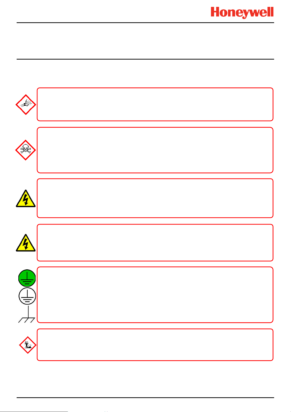
Touchpoint Plus is Not ATEX/IECEx certified, and it shall only be installed in safe areas where there are no
Touchpoint Plus is suitable for use in Class I, Division 2, Groups A, B, C, and D or non-hazardous locations only.
Lithium batteries may cause severe injury or death if swallowed, and may catch fire or explode if mishandled,
Always handle batteries with care, keep them out of the reach of children, and dispose of them carefully in
Batteries (regardless of type) shall only be handled, fitted, removed or replaced in non-haz ardou s (safe) area s.
All power supplies must be hard wired and must include a circuit breaker (RCD / RCCB) and, close by and
unobstructed, a means of manually isolating and locking–out the power supply without breaking the protective
Lethal current may be present in this equipment when electrical power is applied and after it is removed. There is
Isolate power before opening electrical access panels. Ensure residual current is fully discharged before touching
Lethal current may be generated both internally and externally to the system. All installations, including
enclosures and external units, must be grounded to protective earth, and must be capable of staying earthe d
The Protective Earth (Ground) symbol is shown to the left, and it always has a green background. Do not confuse
The Touchpoint Plus system and/or its sensors may become contaminated by the ambient environment in which
it or they are used. It is the Customer’s sole responsibility to ensure that all appropriate safety precautions are
DANGER – IGNITION HAZARD
flammable atmospheres, and where oxygen concentrations cannot exceed 25% v/v O
WARNING – LITHIUM BATTERY HAZARDS
recharged, burned or disposed of incorrectly.
accordance with local regulations.
WARNING – LETHAL VOLTAGE PRESENT
earth (ground) connection.
Removable plug/socket connection is not permitted under any circumstance.
WARNING – LETHAL VOLTAGE PRESENT
a risk of death or injury from electrical shock when access doors are open.
WARNING – LETHAL VOLTAGE PRESENT
(grounded) when the power supply is interrupted.
it with the chassis earth and equipment earth symbols shown below it.
WARNING – TOXIC WASTE AND HARMFUL BY-PRODUCTS
taken before handling any components or transferring them to any other party.
.
2
MAN0984_Iss 3_02/16 Touchpoint Plus
Pt. No. 3011M5001_3 6 Technical Handbook
Safety Hazards, Warnings And Cautions
2.1.2 Safety Hazards (Cont.)
The following general hazards are associated with the use of this equipment:
DO NOT USE WATER if a lithium battery overheats or burns, as it may make the fire worse and it may cause an
This equipment contains a number of potentially toxic substances that may pose a health or environmental
hazard if exposed to very high temperatures, VOCs or corrosives, or if improperly handled or disposed of.
Each Touchpoint Plus enclosure is heavy and weighs considerably more when packed. Ensure that a Manual
Handling Risk Assessment is carried out before moving or installing the system, and ensure that enclosures are
Touchpoint Plus uses high energy AC and DC currents that may cause arc ing and spar ks if shorted out. Always
Touchpoint Plus can be used to control loud alarms and sirens. Always wear hearing protection when working in
Touchpoint Plus houses static-sensitive component s. Alw ay s isol ate power and discharge circuits before
Batteries may explode if mistreated. Do not disassemble them or dispose of in fire.
CAUTION – HEALTH AND ENVIRONMENTAL HAZARDS
fitted securely to a suitable vertical surface. Do not place objects on the enclosures.
Always follow a Safe System of Work when carrying out any work involving Safety Systems.
WARNING – FIRE OR EXPLOSION HAZARD
WARNING – DO NOT USE WATER
explosion.
Evacuate the area immediately and call Emergency Services.
CAUTION – RISK OF INJURY AND DAMAGE
CAUTION – RISK OF EYE INJURY
wear eye protection when the enclosure is open.
CAUTION – RISK OF HEARING DAMAGE
the vicinity of loud or high-pitched noises.
CAUTION – RISK OF EQUIPMENT DAMAGE
touching internal components. Always take anti-static precautions.
CAUTION – RISK OF INJURY OR DAMAGE
MAN0984_Iss 3_02/16 Touchpoint Plus
Pt. No. 3011M5001_3 7 Technical Handbook
Safety Hazards, Warnings And Cautions
2.2 Location and Description of Warning Labels
2.2.1 Safety Warning Labels
In accordance with the requirements of European Standard EN 60825–1, appropria t e warning labels are mounted in
specified locations on the equipment. This is to indicate conditions under which the user could be subjected to electrical
hazards.
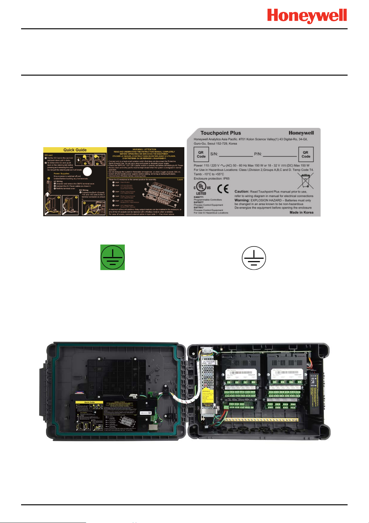
Figure 1. Quick Start Guide Label
(Not to Scale)
Figure 3. Protective Earth (Ground) Point Figure 4. Equipment Earth (Ground) Point
This Protective Earth (Ground) location point label is
used inside the system and is not normally visible to
the operator.
Figure 5. Internal Label Positions
This Equipment Earth (Ground) location point label is
used inside the system and is not normally visible to
the operator.
Figure 2. Rating Label
(External – Not Shown Below)
MAN0984_Iss 3_02/16 Touchpoint Plus
Pt. No. 3011M5001_3 8 Technical Handbook
Safety Hazards, Warnings And Cautions
2.3 Electrical Hazards
Gas detection systems contain electr i cal sup pli es that are potentially dangerous and hence suitable precautions must
be taken to prevent the risk of electrocution. This is especially important when untrained/unqualified persons are
allowed to open the enclosure (e.g. to access/remove/refit the SD Card).
2.3.1 General Safety Precautions
• Read the relevant manual before beginning any operating or service procedures.
• Only personnel trained and certified by Honeywell are authorised to service, fit or remove internal parts.
• Only the minimum number of trained personnel, consistent with safety, should have access to the area while work is
being carried out. If necessary, erect warning signs and barriers.
• Follow accepted working procedures and codes of practice as well as the electrical safety code for the site where the
equipment is installed.
• Never operate the equipment under normal conditions with d oor s open, access panels removed or shorting links
fitted.
• Do not ‘Live Test’ without a Safe System of Work (SSoW).
• Always keep the area around the equipment dry and free of obstructions.
• Switch off and Isolate the equipment if water ingress is suspected or confirmed.
• Never operate the equipment if any Mains power cable is frayed or damaged.
• Never wear wristwatches, rings, bracelets, or other jewellery when working around electrical circuits or moving parts.
• Take anti-static precautions when working on electronic circuits.
• Never work on electrical equipment alone.
2.3.2 Component Testing and Replacement
Before carrying out any electrical testing or component replacement:
• Read this Manual to become familiar with the location of high voltage components.
• Isolate the system at the main circuit breaker, lock it in the ‘Off’ position, and attach a notice indicating that
maintenance work is in progress.
• Always wait for 5 minutes after isolating the equipment to ensure that stored energy has dissipated.
• Never assume the polarity of cabling or replacement components. Refer to electrical schematics or contact Honeywell
for confirmation.
• Use only Honeywell approved replacement parts.
Only Honeywell trained and certified maintenance technicians are authorised to carry out component testing and
replacement. Unauthorised work may result in a potentially dangerous situation and will invalidate the
Antistatic Precautions are required to prevent severe damage to electronic components.
WARNING – UNAUTHORISED PERSONNEL
ANTI–STATIC PRECAUTIONS
manufacturer’s warranty.
MAN0984_Iss 3_02/16 Touchpoint Plus
Pt. No. 3011M5001_3 9 Technical Handbook
Safety Hazards, Warnings And Cautions
Antistatic Precautions
As with all modern electronic circuits, the Printed Circuit Boards (PCBs) in Touchpoint Plus systems utilise some static-
sensitive components that can be severely damaged if subjected to static discharge. Static can be generated on the
human body by friction or movement and is discharged through the first contacted route to earth. It can also jump gaps
between items of differing electrical potential.
Static damage is not always immediately apparent and can cause component failure at any time after the static discharge
has occurred. It is, therefore, very important that everyone takes the following precautions when handling PCBs:
• An industry approved antistatic wrist strap, containing a resistive component greater than 1Megohm, must be worn
and connected to an effective earth (ground) point. The continuity between the strap and earth (ground) must be
checked regularly.
• PCBs must only be handled by their non-conductive edges. Do not allow any components, conductive tracks or
contacts to come into proximity with the body, clot hing , machinery, power source or any material other than a staticdissipative mat.
• W ith the exception of assemblies containing batteries, anti-static packaging must be used for transporting PCBs and
Integrated Circuits (ICs). All Touchpoint Plus electronic components are ship ped in appro priate packaging that can be
re-used when returning items for test or repair.
• Avoid wearing clothing manufactured from, or containing a high proportion of, man-made fibres. These can build up a
high static potential that may not be discharged through the body or wrist strap.
An effective earth (ground) point is the protective earth (ground) bus bar inside the enclosure. This can be used to connect
a suitable anti-stat ic w r ist st rap provided that the Gas detection system is connect ed to protective earth (ground) via the
mains power supply cable.
If installed correctly, the equipment earth (ground) point is connected directly to mains earth (ground) via
protective earth and the mains power supply cable, and the e arth (ground) circuit cannot be broken by operating
the Isolator switch or circuit breaker.
IMPORTANT
2.3.3 Good Practice
After switching off the system, it is good practice to wait at least 15 seconds before switching it on again. This allows the
circuits and RAM to dis charge adequately before being powered-up again. Failing to do so may cause data corruption.
2.3.4 Lithium Battery Hazard
Lithium batteries are fitted to Touchpoint Plus as backup power sources.
Replace the factory installed battery pack TPPLOIBB with Honeywell Analytics Asia Pacific replacement battery pack part
no. TPPLSIBB and the PCB CMOS battery with type CR2032 only.
Use of other batteries may present a risk of fire or explosion.
Lithium batteries may cause severe injury or death if swallowed, and may catch fire or explode if mishandled,
Always handle lithium batteries with care, keep them out of the reach of children, and dispose of them carefully
Batteries shall only be fitted, removed or replaced in non-hazardous (safe) areas.
LITHIUM BATTERY TOXIC AND FIRE HAZARDS
recharged, burned or disposed of incorrectly.
in accordance with local regulations.
MAN0984_Iss 3_02/16 Touchpoint Plus
Pt. No. 3011M5001_3 10 Tec hnical Handbook
Safety Hazards, Warnings And Cautions
Product Compliance
This product complies with the following standards and directives.
Other safety directives may apply to the complete system installation if an OEM’s product is integrated into other
equipment or machinery.
Safety Compliance
Hazardous Location
(Non-Incendive)
Electrical Safety
EMC/RFI
Low Voltage Directive
Gas Performance*
* ISA 12.13.01 and CSA C22.2 No.152 approvals are applicable only to mV sensors Model 705 and MPD or any suitably
certified mA sensor.
Note: The Equipment referred to in this manual contains components and assemblies that are each certified for use in a
variety of differing environments, and it is the site owner’s responsibility to confirm the suitability of the equipment prior to
its installation and use.
Please check the product rating plate and look for the following marks to ensure that the supplied equipment is
suitable for its intended location and purpose:
Products bearing the CE mark conform to all applicable European Directives as stated on the Honeywell product specific
EC Declaration of Conformity.
Products bearing the UL mark conform to the requirements for Ordinary Locations. The letters C and US mean that the
product is certified for use in Canada and the United States of America.
Read and understand the instruction manual before operating or servicing the equipment.
Class 1, Division 2, Groups A,B,C,D, Temp. Code T4
ISA 12.12.01-2013
CSA C22.2 No. 213-M1987
CAN/CSA C22.2 No. 61010-1 and No.142
UL 61010–1 (3
IEC/EN 61010–1 (3rd Edition)
EN 50270
IEC/EN 61010–1 (3
ISA 12.13.01 and CSA C22.2 No. 152
rd
Edition); UL508
rd
Edition)
IMPORTANT
MAN0984_Iss 3_02/16 Touchpoint Plus
Pt. No. 3011M5001_3 11 Tec hnical Handbook

Safety Hazards, Warnings And Cautions
Conditions of Use
This Touchpoint Plus equipment shall only be operated:
• By properly trained personnel.
• Under Honeywell approved conditions.
• W ith due authorisation.
• Using approved maintenance and servicing procedures.
2.3.5 Training of Personnel
Honeywell and / or its distributors can provide training for operators and maintenance personnel. Personnel who have
been trained in operation and maintenance shall be limited to carrying out only those procedures and tasks taught during
the training course. Honeywell certified maintenance technicians must carry out all other tasks.
Honeywell can also provide additional or advanced training. Retraining is recommended periodically and whenever the
equipment / installation is changed or upgraded.
2.3.6 Conditions Satisfying Local, National and International Safety Regulations
Approved conditions must satisfy the requir em ents of applic able national and international safety standards and statutory
requirements relating to electrical, EMC, and health hazards. In addition, they must satisfy the requirements of the Site
Safety Officer and the local safety regulations.
2.3.7 Due Authorisation
Before any production, maintenance, or servicing procedure is carried out; written authorisation must be obtained from
one of the following personnel to confirm that the proposed task satisfi es the nec es sary safe ty conditio ns:
• A competent authorised person having a professional qualification in an appropriate technical discipline.
• The Factory, Technical or Engineering Manager responsible for the working area.
• The Site Safety Officer or an authorised Honeywell representative or approved distributor.
2.3.8 Approved Maintenance and Servicing Procedures
Approved Maintenance and Servicing Procedures are those stipulated in this manual or as authorised separately by
Honeywell.
It may be necessary to establish a temporary Locally Controlled Area (LCA) to restrict access during maintenance, testing
or servicing of this equipment.
MAN0984_Iss 3_02/16 Touchpoint Plus
Pt. No. 3011M5001_3 12 Tec hnical Handbook
System General Description
SD Card
Audio / Visual Alarm
mA Loop Sensors
Relays / Actuators
mA Loop
mV Bridge Sensors
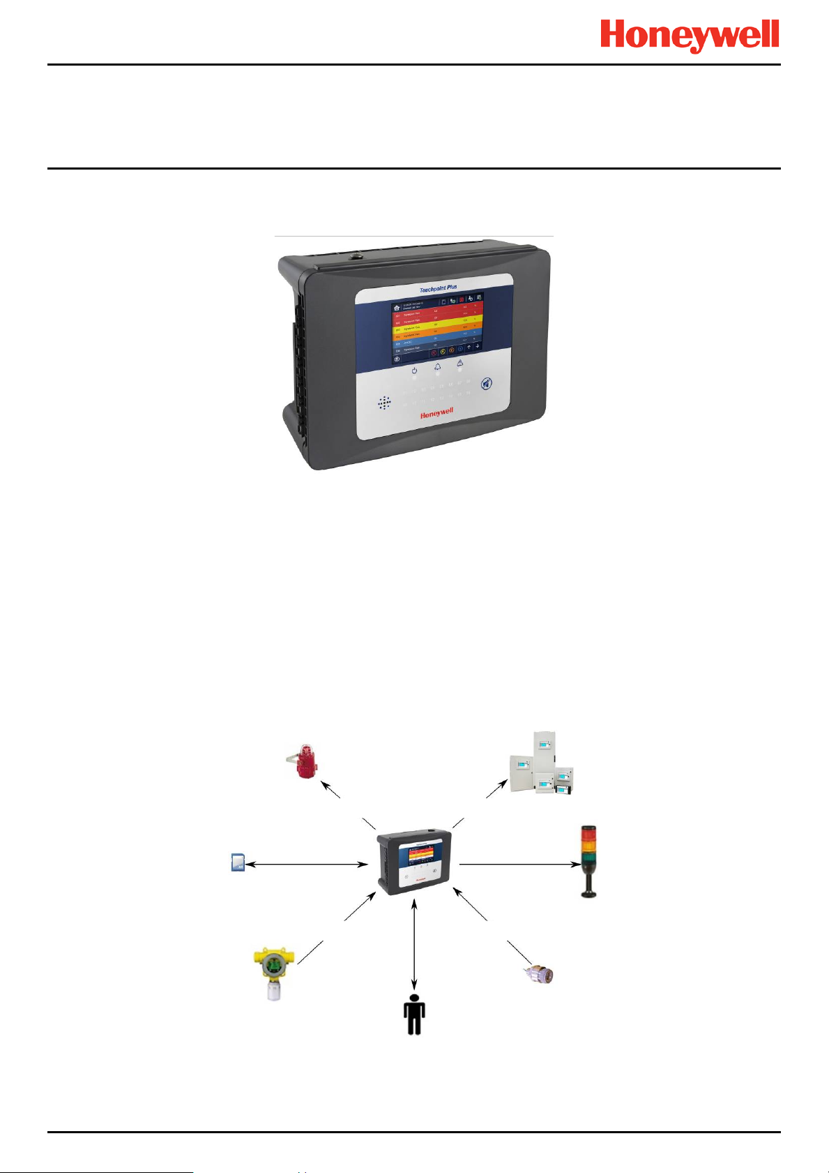
Chapter 3. System General Description
Figure 6. T ouchpoint Plus Wall-Mounted Controller
The Touchpoint Plus is an entry level (or upgrade) touch-screen digital Controller for general industrial and commercial
gas detection systems. It has eight input channels, with a further eight channels available through an optional expansion
unit (see Note below).
It can handle a wide range of milliamp, millivolt, and catalytic sensors through analogue inputs, and it can contr ol vari ous
outputs such as audible and visible signals and solenoid valves.
The cabinets are constructed from high-impact plastic and have fully-sealed, easy opening access. They are supplied with
a wall mounting or can be directly mounted to any solid vertical surface or rack. Cable entry is via entry glands on the
lower side.
Touchpoint Plus is rated IP65, which means that it is dustproof and can be subjected to low-pressure water without
significant ingress. This makes it particularly suited to offices, control rooms and unheated boiler rooms.
Note: Currently Touchpoint Plus is only available as a composite Gas Detection System, but please contact Honeywell
Analytics for details about future upgrades.
Figure 7. Typical Installation Options
MAN0984_Iss 3_02/16 Touchpoint Plus
Pt. No. 3011M5001_3 13 Tec hnical Handbook
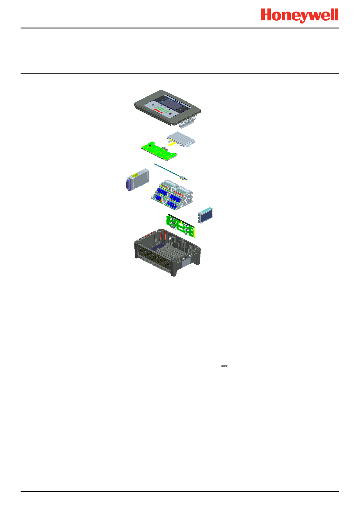
System General Description
Enclosure Door
with Touchscreen
Motherboard
SMPS
Modules
Backplane
Enclosure
LCD Unit
Common Data
Communication Cable
Backup Battery
Figure 8. TPPL Controller Exploded View
Both the Touchpoint Plus and its optional expansion unit have the option for AC, DC and battery backup power supplies,
but the optional Expansion Unit has no motherboard or display (LCD).
Features of the Controller unit:
• Colour LCD Touch Screen with multi-language GUI and menus
• Password protection
• Flexible Mains Power Input: 50 – 60 Hz 110/220 V ~ (AC), 18 – 32 V
for combined Base and Expansion Units
• Up to 8 channels of Analogue Input (0–22 mA, Bridge mV for Cat bead)
• 2 or 3-wire signal inputs
• Up to 24 channels of user configurable relay controlled Output
• Up to 8 channels of configurable mA Output
• Alarm update on Acknowledge
• Automatic Self-Diagnostic with error codes
• Event recording
• SD Card
(DC), Max 105 W for a single unit or 210W
Pt. No. 3011M5001_3 14 Tec hnical Handbook
MAN0984_Iss 3_02/16 Touchpoint Plus
System General Description
1 2 3
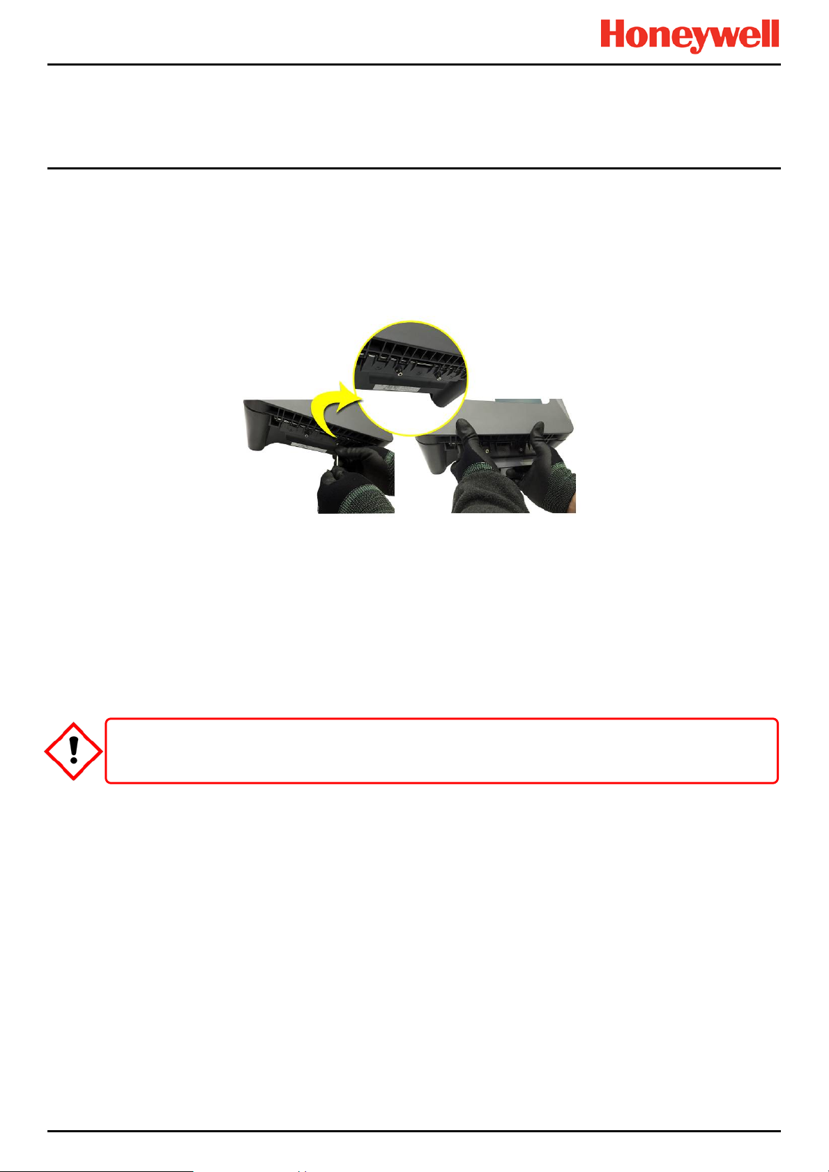
3.1 How to Open and Close the Enclosure
1) Ensure that it is safe to open the enclosure and, if necessary switch off and isolate electrical power.
2) Unscrew the two x 3 mm Hex socket security screws (1) until they become loose (2).
3) With a gloved hand only, pull the handle until it comes free (3). Do not apply undue force.
4) Open the enclosure door fully.
Figure 9. Undoing the Two Security Screws and Opening the Enclosure
5) Closure is the reverse of this procedure, but care must be taken not to exert undue force, and you must not press on
the membrane or touch screen areas.
Note: The door recess has an environmental seal that requires some pressure to close the door correctly. The enclosure
handle is the primary method of applying this pressure but you can assist it by pressing firmly on the door edge directly
above the handle as you press on the handle itself.
TPPL enclosures must be fully closed and secured during normal operation.
CAUTION
MAN0984_Iss 3_02/16 Touchpoint Plus
Pt. No. 3011M5001_3 15 Tec hnical Handbook
System General Description
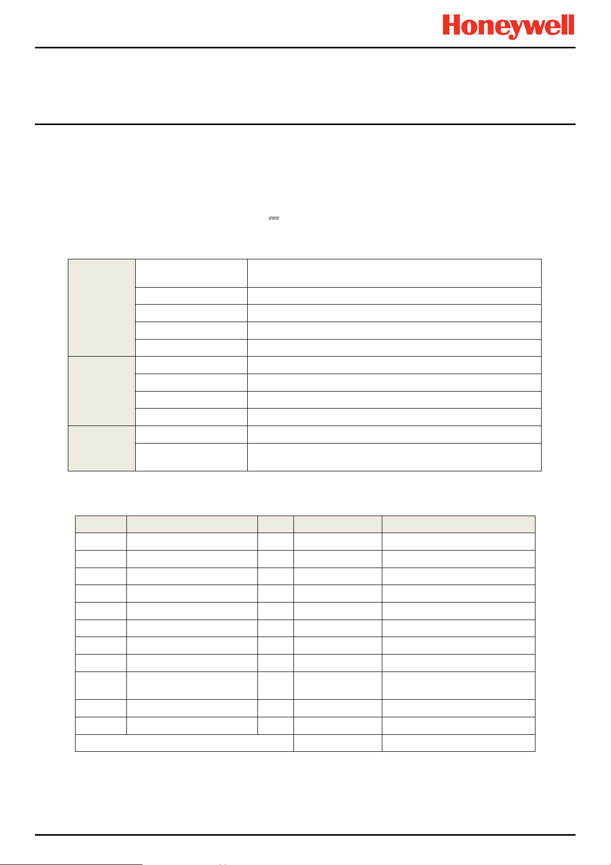
3.2 Equipment Specification
3.2.1 Power Requirements (Controller Unit only)
The Touchpoint Plus system is designed to operate on a single phase, 50 to 60 Hz, 110/220 V~ (AC) supply with a typical
power consumption of less than 105 W.
Alternatively it can be connected to an 18–32 V (DC) supply with typical power consumption less than 105W.
The system can contain an optional backup battery to guard against short-term power disruption.
Voltage Range AC
AC Frequency Range 50 – 60 Hz ± 6%
Input
Output
Protection
Nr. Power Usage Qty Max Power (W) Remarks
1 UI Module 1 3.6
2 Main Module 1 1.7
3 mA Input Module 1 0.9 Not includin g Field Device power
4 mA input Field Devices 8 40.0 mA Input Module power only
5 mV Input Module 1 8.5
6 Dual Input Module 1 9.4
7 mA Output Module 2 8.6
8 Relay Output Module 2 2.0
9
10 Audio/Visual Alarm 4 28.8
11 SMPS Power Loss — 14.0
MAXIMUM PERMITTED CONSUMPTION 104.9
AC Current Draw (typ.) 3 A @ 115 VAC, 2A @ 230 VAC
Cold-start Current (typ.) 40 A @ 230 VAC
Leakage Current <2 mA @ 240 VAC
DC Voltage 24 V
Rated Current 6.5 A
Current Range 0 – 6.5 A
Rated Power 156 W
Overload 110 – 150 % rated output power
Over-Volt
Table 1. Power Supply (SMPS RS–150–24) Electrical Ratings
Charging power for backup
battery pack
AC 110/220 V manually switchable
300 VAC surge for 5 sec without damage
27.6 – 32.4 VDC Hiccup mode, which recovers automatically when
the fault is removed.
1 5.3
Table 2. Maximum Power Consumption Calculations
MAN0984_Iss 3_02/16 Touchpoint Plus
Pt. No. 3011M5001_3 16 Tec hnical Handbook

3.2.2 Weights
Note: Based on one input module, two mA output modules, two output relays, SMPS and backup battery for the basic unit
and expansion unit respectively.
3.2.3 Dimensions
System General Description
TPPL Basic Unit TPPL Expansion Unit
System alone
System with packaging
Table 3. System Weights
External Dimension Millimetres Inches
Depth
Length
Width
Table 4. System Dimensions
8.5 Kg (18.7 lbs) 8 Kg (17.6 lbs)
9 Kg (20 lbs) 8.5 Kg (18.7 lbs)
156 6.2
426 16.9
300 11.8
3.2.4 Ambient Operating Temperature
–10 °C to +55 °C (14 °F to 131 °F)
3.2.5 Overall Ambient Operating Humidity
5 % to 95 %RH, non-condensing
3.2.6 Storage Conditions (Without batteries)
–25 °C to +60 °C (-13 °F to 140 °F), @ 5 % to 95 %RH, non-condensing
3.2.7 Storage Conditions (With batteries)
1 year: –20 °C to +25 °C (–4 °F to +077 °F)
3 months: –20 °C to +45 °C (–4 °F to +113 °F)
1 month: –20 °C to +60 °C (–4 °F to +140 °F)
3.2.8 IP Rating
The enclosures are sealed to IP65 when appropriate cable entry glands are used.
3.2.9 Construction
The system cabinets are constructed from PC ABS plastic with a secured quick release front access door panel.
The Controller door panel holds a touch sensitive colour LCD with a membrane cover over additional buttons, LEDs and
an audible warning horn.
Inside the Controller cabinet is a Switched-Mode Power Supply (SMPS) providing a nominal DC 24 V output, an optional
Lithium-ion backup battery, a Main Module, a mA/mV Input Module, two mA Output Modules, two Relay Modules,
protection fuses, and the control and user interface electronics.
The optional expansion unit holds the same modules and optional backup battery, but has no controller or user interface.
Both enclosures contain a common Earth (ground) rail that must be bonded to Protective Earth (Ground) through an
isolation switch that does not disconnect the Earth line.
MAN0984_Iss 3_02/16 Touchpoint Plus
Pt. No. 3011M5001_3 17 Tec hnical Handbook
System General Description
1
2 4 5 6 7
14
11
15
3
10 8 9
16
13
12
3.2.10 Touchpoint Plus Packaging
• Touchpoint Plus outer packaging is made from cardboard. Facilities for recycling are widely available.
• Touchpoint Plus inner packaging is made from Stratocell
recycled into new Stratocell
®
where such recycling facilities exist.
3.2.11 Packaging Components for Return to Manufacturer
Honeywell is unable to accept any consignment that does not conform to the European Classification, Labelling and
Packaging (CLP) Regulations (EC) 1272/2008.
Please consult your distributor, supplier, or the manufacturer if you require further advice.
3.2.12 Disposal (WEEE Directive)
The system contains Lithium batteries and a number of homogenous hazardous materials. These should be disposed of
carefully in accordance with the WEEE Directive and local laws and guidelines. Under no circumstances can they be
disposed of as domestic waste.
3.3 TPPL Construction
The TPPL system consists of a basic Control Unit and an optional Expansion Unit, as shown below.
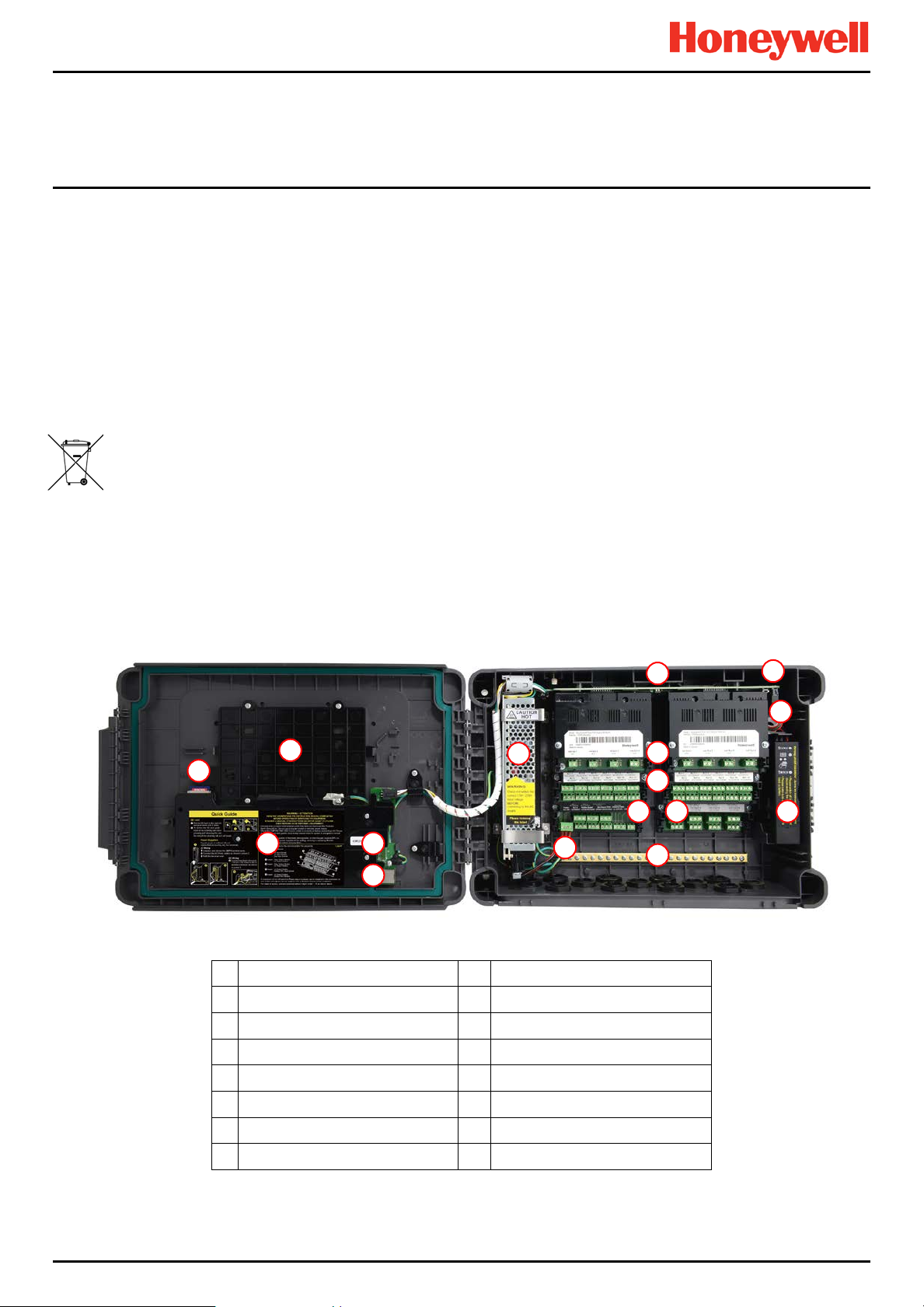
3.3.1 TPPL Basic Control Unit
This figure shows the building blocks of the basic Touchpoint Plus system.
Figure 10. Controller Unit Layout Before Installation
®
, Low-Density Polyethylene (LDPE) foam. The foam can be
1
Touchscreen PCB
2
SD Card
3
Motherboard
4
Modbus Terminals (option)
5
Ethernet Connector
6
Switched Mode Power Supply
7
DIP Switch (on backplane)*
8
Battery On / Off Switch
* The DIP Switch (14) is used to enable / disable the optional expansion box. See Ch.3.3.3 TPPL DIP Switches for further
information.
MAN0984_Iss 3_02/16 Touchpoint Plus
Pt. No. 3011M5001_3 18 Tec hnical Handbook
9
Battery Connector
10
mA Output Modules
11
Relay Output Modules
12
Main Module
13
Input Module (mA/mV/Dual)
14
Backup Battery
15
Power Terminal
16
Earth (Ground) Bus Bar
System General Description
1 2 4
5
6
7
14
11
15 3 10 8 9
16
13
12
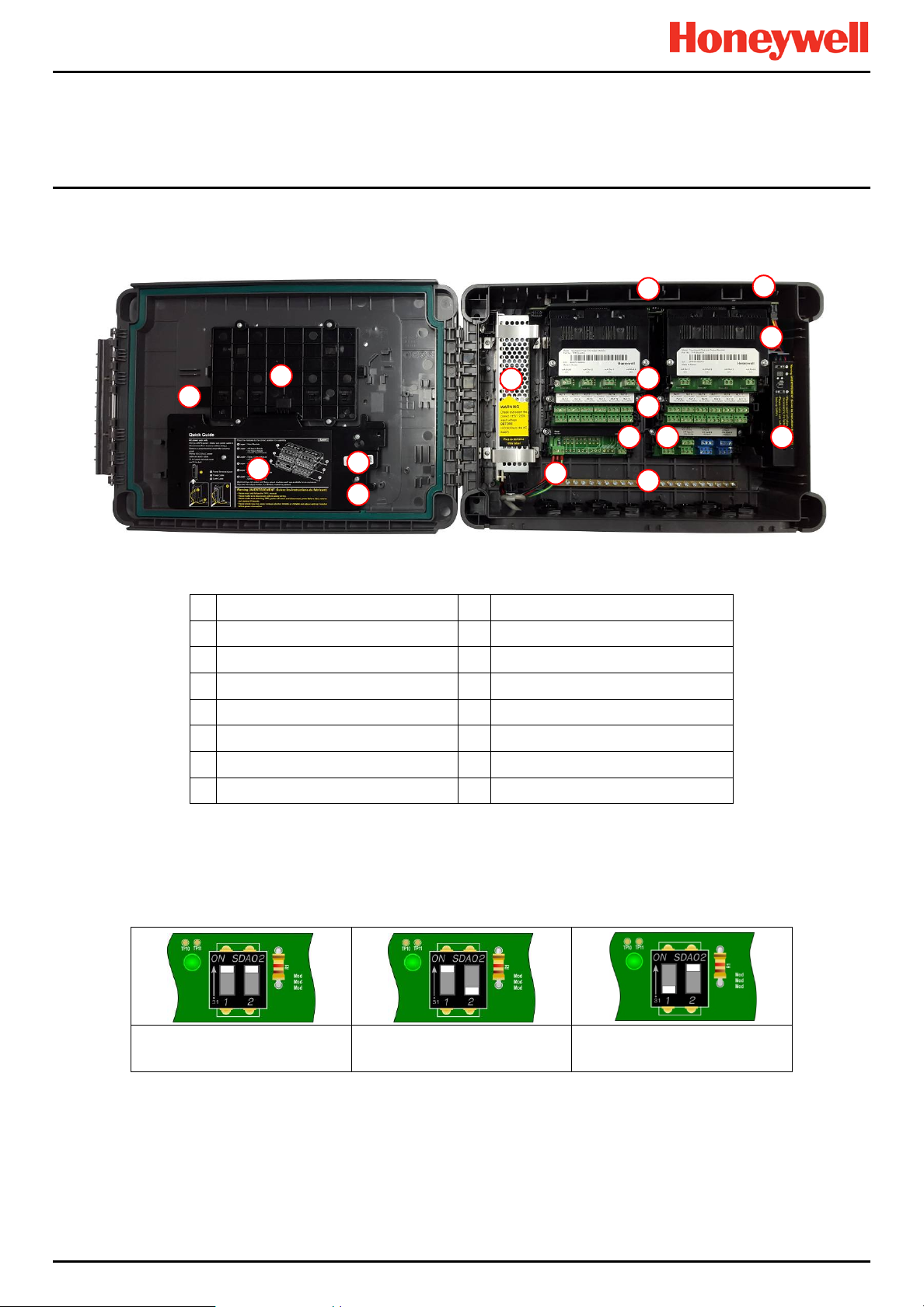
3.3.2 TPPL Expansion Unit
This figure shows the building blocks of the Touchpoint Plus Expansion Unit.
Figure 11. Expansion Unit Layout Before Installation
1
No Touchscreen
2
No SD Card
3
No Motherboard
4
No Modbus Terminals
5
No Ethernet Connector
6
Switched Mode Power Supply
7
DIP Switch (on backplane)*
8
Battery On / Off Switch
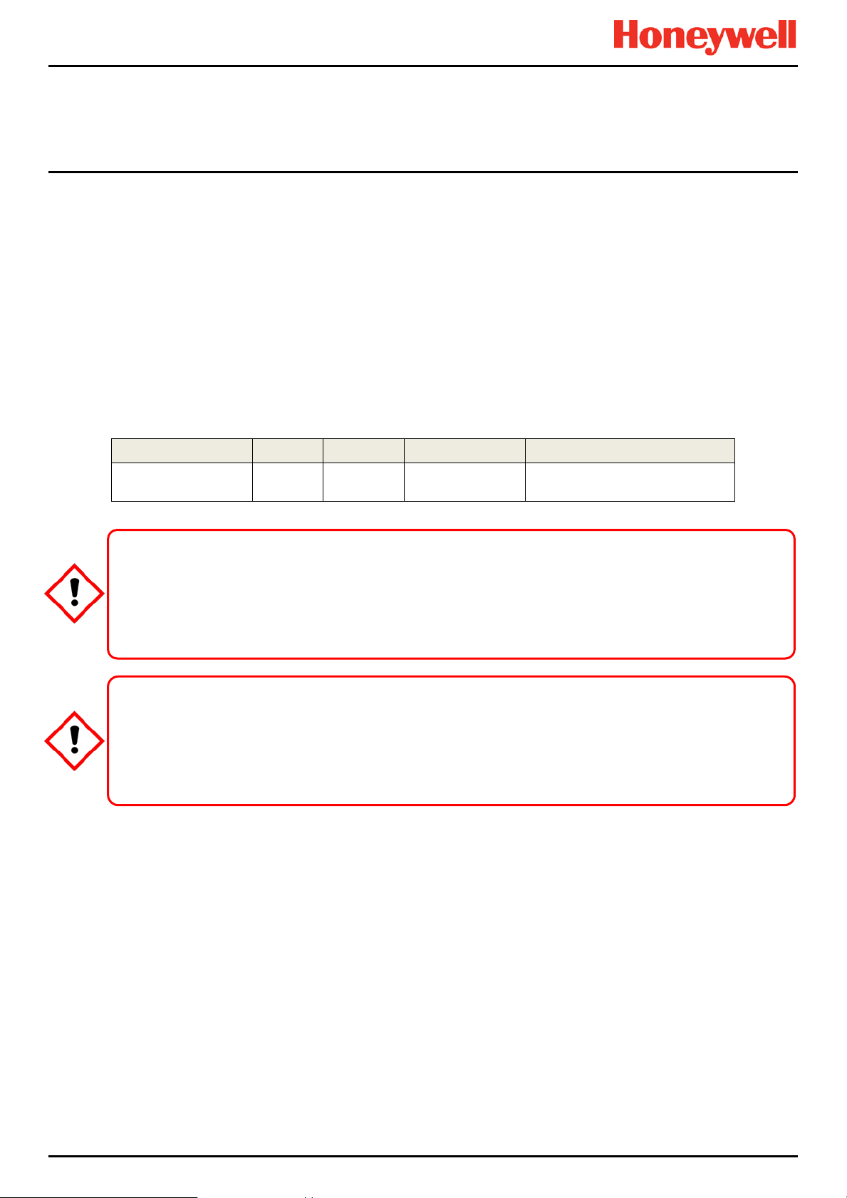
3.3.3 TPPL DIP Switches
TPPL Backplanes have a DIP switch (item 14 in the figures above) that controls the interaction between the master (basic)
and the optional expansion unit backplanes. Once set these DIP switches need not be altered.
Basic Unit
Both On
9
Battery Connector
10
mA Output Modules
11
Relay Output Modules
12
Main Module (Power and CAN only)
13
Input Module (Dual shown)
14
Backup Battery
15
Power Terminal
16
Earth (Ground) Bus Bar
Basic Unit with Slave
1 On, 2 Off
Expansion Unit
1 Off, 2 On
Figure 12. Backplane DIP Switch Settings
MAN0984_Iss 3_02/16 Touchpoint Plus
Pt. No. 3011M5001_3 19 Tec hnical Handbook

System General Description
This page deliberately blank.
MAN0984_Iss 3_02/16 Touchpoint Plus
Pt. No. 3011M5001_3 20 Tec hnical Handbook
System Mechanical Installation
Chapter 4. System Mechanical Installation
The system can be directly wall-mounted or on an optional mounting fixture. Whichever method is chosen, the mounting
must be sound, secure, and capable of supporting the weight of the enclosure plus the weight of any cables and glands.
When choosing a location, it must be easily visible and accessible, with room to mount an external power isolator. There
must also be room to fully open the access door, which opens to the left, and room to easily access the door locking
handle and its securing screws, which are situated on the right. If using the optional expansion unit there must be
sufficient room between them to access the locking handle and its securing screws.
The units should be mounted so that the screen can be easily accessed and seen, but they should not obstruct accesses,
walkways or exits.
Although the units are IP65 when installed correctly, they should be mounted away from heat sources, out of direct
sunshine, and should be protected from rain, severe weather, steam or excess humidity and condensation.
These units have only passive cooling, so an adequate airflow must be maintained to prevent overheating.
Assembly IP NEMA Pollution Degree Remarks
Wall mounted cabinet 65 4X 2
It is the Customer’s responsibility to ensure that the equipment is correctly installed, and that cable entry glands
Failure to do so will invalidate the quoted IP / NEMA / Pollution ratings and may invalidate the warranty.
The units as supplied have two hex-socket securing screws in the access door handle, and these have to be fully
unscrewed prior to opening the handle. Failing to do so could cause irreparable damage to the housing.
The handle must be correctly locked and the screws must be correctly tightened when the unit is in normal
operation. Failing to fully secure the enclo sur e is unsafe and will invalidate product certification.
or blanks of the appropriate IP rating are correctly used.
CAUTION
CAUTION
When properly installed using the
appropriate cable entry glands
MAN0984_Iss 3_02/16 Touchpoint Plus
Pt. No. 3011M5001_3 21 Tec hnical Handbook
System Mechanical Installation
Minimum Left Wall
Clearance 200 m m
Minimum Right Wall
Clearance 150 mm
Minimum Ceiling
Clearance 250 m m
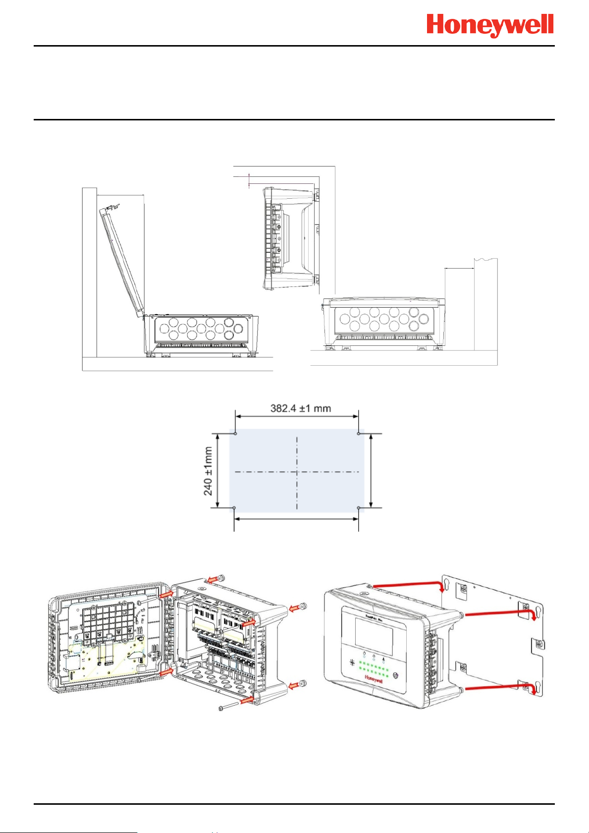
4.1 Wall Mounting Requirements
For details and drawings please refer to Pt. No. 3011G0459_F Installation Clearance pdf.
Figure 13. Installation Clearance Measurements
Figure 14. Wall Mounting Template
Figure 15. Wall and Plate Mounting Points
You can use the wall mounting plate as its own template and location guide, and you should ensure that the mounting
bolts are adjusted to fit the plate bayonet holes before fixing the plate to the wall.
MAN0984_Iss 3_02/16 Touchpoint Plus
Pt. No. 3011M5001_3 22 Tec hnical Handbook

System Mechanical Installation
Enclosure Corner
Plate
should be determined by the surface material and the type of anchor required.
4.1.1 Wall Mount Fixings
You will require the following locally sourced items to install the Touchpoint Plus:
Tool to undo the enclosure access handle security screws:
• 3 mm Hex key
Suggested Fixings to screw the enclosure to the wall only:
• Screw Max. Dia.: 6.4 mm (#14) dome or cheese head screw
• Screw Min. Length: 76 mm (3 in.) – Normal fix
• Washer Max. Dia: 14.3 mm (0.56 in.)
Suggested Fixings for using the Mounting Plate:
For the plate, choose fixings appropriate to the surface and the weight of the enclosure plus cables. You will also need to
use suitable bolts, washers and lock nuts (see diagram below).
Ideally you will mount the enclosure and cables on a ≥20 mm ply board to allow cable troughs to be used.
The sizes above are given to allow for clearance in the TPPL Enclosure. The actual length and type of fixing
CAUTION
Wall or
Board
Figure 16. Fixing Orientation When Using the Optional Mounting Plate
Note:
You should ensure that washers between the TPPL enclosure and the wall or mounting plate are sufficiently large to
spread the load evenly.
• For metal conduit, use a metal ground plate (e.g. use Honeywell Part No: TPPLOMGND).
• For external visual/audio outlet, ensure IP65 is maintained (e.g. use Honeywell Part No: M-700123, available in the
Americas and AsiaPac only).
• For cable glands, use type PG16 glands tightened to 5 Nm (44.2 lb-in) torque.
MAN0984_Iss 3_02/16 Touchpoint Plus
Pt. No. 3011M5001_3 23 Tec hnical Handbook

System Mechanical Installation
This page deliberately blank.
MAN0984_Iss 3_02/16 Touchpoint Plus
Pt. No. 3011M5001_3 24 Tec hnical Handbook

System Electrical Installation
Chapter 5. Electrical Power Connection and Interfacing
All power supplies must be hard wired and must include a circuit breaker (RCD / RCCB), and (close by and
unobstructed) a means of manually isolating and locking out the power supply without breaking the protective
Removable plug and socket connection is not permitted under any circumstance.
Lethal current may be present in this equipment when electrical power is applied. There is a danger of death or
injury from electrical shock. Isolate power before opening electrical access panels. Ensure residual current is fully
Lethal current may be generated both internally and externally to the system. All installations, including remote
units and cables, must be connected to protective earth, and must be capable of remaining so when the power
Honeywell can accept no responsibility for any damage or injury caused by incorrect or faulty wiring.
It is the customer’s responsibility to provide appropriate power supplies to the TPPL and detectors.
WARNING – ELECTRICAL SHOCK HAZARD
earth (ground) connection.
WARNING – ELECTRICAL SHOCK HAZARD
discharged before touching live termina ls.
WARNING – ELECTRICAL SHOCK HAZARD
supply is interrupted.
Protective earth is shown by the green symbol on the left.
WARNING
5.1 Power Connection
Every TPPL Controller and Expansion Unit is factory set to operate at a manually switchable voltage of AC 110/220 V on
single phase, 50 to 60 Hz power supplies. They can also be connected to DC 18 – 32 V SELV supplies with their backup
battery removed, or DC 24 – 32 V SELV supplies with a battery fitted (24 V is the battery’s minimum charg ing current).
TPPL Controller and Expansion Units each have a typical peak power consumption of less than 105 W, and they must be
directly connected to power supplies via a Main Isolator Switch that leaves protective earth (ground) permanently
connected. The circuit should incorporate a Residual Current Device (RCD) or Residual Current Circuit Breaker (RCCB).
TPPL systems are not certified for connection to domestic or fluctuating power supplies.
The system is normally supplied with the voltage pre-set to the customer’s specificatio n. Bef ore con nect ing to
Mains Power check the SMPS voltage setting and correct as necessary. Remove the yellow label when done.
MAN0984_Iss 3_02/16 Touchpoint Plus
Pt. No. 3011M5001_3 25 Tec hnical Handbook
WARNING

AC Line
AC Common
F – Ground (Not Used)
AC Input
DC Output
-Ve DC
-Ve DC
+24 VDC
+24 VDC
+24 V DC In
Ve DC Return
Earth (Ground)
Protective
System Ground Bus Bar
5.1.1 AC Power Supply
To confirm or alter the pre-set operating voltage, open the system front cover, locate the SMPS transformer on the left
side and, if required, change the voltage selector using a screwdriver at the point shown by the yellow and black label
below:
System Electrical Installation
-
Earth
(Ground)
Figure 17. Switched Mode Power Supply (SMPS) Connections
Note: Mains Earth (Ground) must only be connected to the protective earth (ground) rail, and not to the SMPS.
Regional power cable wires are coloured in accordance with the following code:
Wire Europe USA CAN India/Pakistan
Protective Earth (Ground) Green + Yellow Green Green Green
Isolated Earth (Ground) — Green + Yellow Green —
Neutral Blue White White Black
Line Brown Blue, Red, or Black Red or Black
Red, Yellow, or
Blue
Table 5. Regional Power Cable Colours
Before making any electrical connections or changes ensure that:
• the mains supply isolator switch is in the Off position
• the system is set up to operate at the correct voltage
Refer to Ch.3.2.1 Power Requirements for further information on system electrical specifications.
Note 1: Input voltage of less than DC 23.5 V will fail to charge the backup battery, and it will generate a ‘Battery
unchargeable’ warning message.
Note 2: If Field detectors exceed 20 W per channel or a combined total of 40 W they may need their own power supplies.
Refer to Table 6: mA Input Module Connections for further information.
MAN0984_Iss 3_02/16 Touchpoint Plus
Pt. No. 3011M5001_3 26 Tec hnical Handbook

+24 V DC In
-V DC Return
Earth (Ground)
buffer time will be reduced if the charging supply is <24 V.
5.1.2 DC Power Supply
It is possible to power the Touchpoint Plus controller directly from a DC 18 – 32 V supply without using AC supplies at all.
However, batteries used alone may quickly drop below the minimum DC 18 V requirement when under load.
Note: The system must still be connected to protective earth (ground) when using an external DC supply.
System Electrical Installation
Protective
Earth
(Ground)
Figure 18. Connections for DC 24 V Supply
System Ground Bus Bar
5.1.3 Backup Battery Pack
TPPL can be fitted with a rechargeable 24 volt Lithium-Ion Battery Pack. This would normally be charged by the SMPS,
but can be charged by a separate DC 24 – 32 V supply. Charging could take up to 24 hours from a fully discharged state.
Note: The backup battery requires a minimum 24 VDC input to fully charge. However it has a non-replaceable 15 A overcurrent protection fuse so the battery input should never exceed 32 V, 5 A.
The battery should be charged at DC 24 – 32 V, 5 A. The backup battery will not become fully charged and the
DANGER
DO NOT USE WATER to cool overheated Lithium batteries
as this can cause them to ignite violently or they may even explode.
IMPORTANT
MAN0984_Iss 3_02/16 Touchpoint Plus
Pt. No. 3011M5001_3 27 Tec hnical Handbook

System Electrical Installation
5.2 Cabling and Connection Requirements
5.2.1 AC Mains Voltage Power Cables
Use a properly rated AC power (mains) cable, certified and installed in accordance with local and national regulations. The
Touchpoint Plus terminals will accept only copper wire sizes in the range 0.4 – 4 mm
core), or 21 – 12 AWG (T
5.2.2 DC Power Cables
Use a properly rated DC power (mains) cable, certified and installed in accordance with local and national regulations. The
Touchpoint Plus terminals will accept only sizes 0.9 – 3.3 mm2 (solid or stranded copper cores), or 18 – 12 AWG (T
>80 °C). The mains terminals should be torqued to 0.5 Nm (4.4 lb-in).
All cabling shall be appropriately rated and approved in accordance with national and local regulations.
Additionally, cabling must satisfy the requirements defined in the manuals of connected field devices, particularly
if the field device is certified for use in a hazardous location.
Signal cables should be shielded to avoid spurious signals , and shall be bonded to protective earth (Ground).
Care must be taken to avoid Ground feedback loops.
All external cables should be fitted through appropriate glands to preserve the IP rating.
>80 °C). The mains terminals should be torqued to 1.35 Nm (11.9 lb-in).
amb
WARNINGS
2
(solid core), 0.4 – 3 mm2 (stranded
amb
5.2.3 Field Device Cables
Field Device cabling (sensors, lights, solenoids, etc.) should be appropriate to the zone classification, and in accordance
with the device manufacturer’s recommendations. Refer to local and national regulations where appropriate, and to the
device’s user manual.
All sensor field cables must be screened and earthed (grounded) in order to:
• ensure correct operation of the system
• avoid spurious signals
• provide lightning protection
• Meet European Standards for RFI and EMC
The I/O modules will accept only copper wire sizes to a maximum of 2 mm² or 14 – 30 AWG, with the terminals torqued to
0.5 Nm (4.4 lb-in).
Ensure that the maximum loop resistance is not exceeded, as specified by the device manufacturer.
Ensure that the correct power level is present at the field device, as specified by the device manufacturer, and does not
exceed the TPPL supply limit of 15W per channel individually or 40 / 68 W in total. (See the notes under 5.2.5 Main
Module Connections for more details about power consumption and availability.)
E.g. if a device’s supply requirement is 24 VDC 0.5 A, then the power requirement is 24 V x 0.5 A (V x I) = 12 W. If you
use 240m of AWG 22 cable (R = 0.05 Ω/m), the power line dissipation is 0.05 Ω/m x 240m x 0.52 A (R x I2) = 3 W.
Therefore the total power requirement is 15 W (12 + 3).
You should also test the cable resistance in situ as its actual resistance is relative to T
end of line (EOL) resistance).
(taking into account any added
amb
MAN0984_Iss 3_02/16 Touchpoint Plus
Pt. No. 3011M5001_3 28 Tec hnical Handbook

AC Line
AC Common
Ground
V DC
DC
VDC
+24 VDC
+24 V DC
DC Return
Earth (Ground)
+24 V DC
DC Return
Earth (Ground)
AC Line
AC Common
Ground
DC
DC
+24 VDC
+24 VDC
Touchpoint Plus Controller
Optional Expansion Unit
5.2.4 Optional Expansion Unit Connection
System Electrical Installation
In general, the expansion unit should have the same cabling and similar power requirements as the Controller:
• Power cable: 2-core plus Earth
• CAN cable <10 metres (32.8 Ft) using 0.2 to 2 mm2 / 14 – 24 AWG shielded twisted pair cable (Belden #9841 or
equivalent)
• Shielded signal cables
• Avoid Earth (Ground) loops
The SMPS can deliver 150 W maximum, however a basic unit and an expansion unit each need 105 W so must be wired
as shown below when using AC Mains input.
–
F-
F-
-
-V
+24
-V
-V
Ground Bus Bar
Ground Bus Bar
Figure 19. Connecting the Touchpoint Plus and Optional Expansion Unit to a Mains Supply
Note: The SMPS is attached to chassis ground and does not need a separate ground connection.
Note: The Main and Expansion Unit power cables should be matched in type and rating.
–
MAN0984_Iss 3_02/16 Touchpoint Plus
Pt. No. 3011M5001_3 29 Tec hnical Handbook

System Electrical Installation
5.2.5 Main Module Connections
Install the power and main module connections as shown below:
Module Label Identifier Terminal Purpose Remarks
+DC 1 24 VDC
Power
RLY1
RLY2
RLY3
Visible Output
Audible Alarm
Ext Alarm PWR
Remote
CAN
–DC 2 0 VDC
–
NC 4
COM 5
NO 6
NC 7
COM 8
NO 9
NC 10
COM 11
NO 12
+24 Vdc 13
VIS 14
Unused 15 —
A1 16 Audible 1
A2 17 Audible 2
F 18 Audible 3
+24 Vdc 19 Ext. Alarm 1
+24 Vdc 20 Ext. Alarm 2
+24 Vdc 21 Ext. Alarm 3
COM 3.3 V 22 Common
RST R1 23 Reset
IHB R2 24 Inhibit
CAN_H 25 CAN_High
CAN_L 26 CAN_Low
3 Earth
Relay 1
Relay 2
Relay 3
Visible
Power Supply In
Channel Relay 001
(Alarm, Fault, Warning Or Inhibit)
Channel Relay 002
(Alarm, Fault, Warning Or Inhibit)
System Relay 003
(System Failure)
Dedicated Alarm
(Max 300 mA) (Note 2)
Dedicated Alarms
(Max 300 mA per channel)
External Alarm Power
(Note 2)
Remote Inputs
(Note 4)
Link to Expansion Unit Option
Figure 20. Basic Unit Main Module Connections
MAN0984_Iss 3_02/16 Touchpoint Plus
Pt. No. 3011M5001_3 30 Tec hnical Handbook

System Electrical Installation
Module Label
Terminal
Identifier
Purpose
Remarks
1
2
25
26
TPPL Controller Unit
Main Module
TPPL Expansion Unit
Main Module
Note 1: +24 VDC Nominal = Controller Input (18 to 32 VDC) – 1.8 VDC (the max voltage drop in the TPPL).
Note 2: Alarm Terminals 13, 19, 20, and 21 can supply +24 VDC at ≤ 28 W combined but this 28 W can instead be used
to increase the power available to field sensors if external audible and visible alarms are not connected. e.g. the 8 sensor
channels would normally have ≤40 W of combined available power, but this can be increased to 68.8 W if terminals 13 –
21 are unused.
Note 3: You must supply sensors with external power if more than 40 / 68 W total power is required (See Note 2).
Note 4: Maximum R
5.2.6 Expansion Module Power Connections
Ensure that the Main and Expansion Unit Firmware versions are matched.
The cables should be fitted through a gland to preserve the IP rating.
resistance for a remote reset/inhibit switch is 18 Ω, i.e. ≤500 m of 1 mm2 shielded cable.
loop
+DC 24 VDC
Power
3
CAN
Figure 21. Expansion Unit Main Module Connections
u
Figure 22. Connecting the Expansion Unit to the Basic Unit
–DC 0 VDC
—
CAN_H CAN High
CAN_L CAN Low
Earth
Power Supply In
Link from Basic Unit
MAN0984_Iss 3_02/16 Touchpoint Plus
Pt. No. 3011M5001_3 31 Tec hnical Handbook

System Electrical Installation
5.2.7 TPPL DIP Switches
TPPL Backplanes have a DIP switch that controls the interaction between the basic (Controller) and the expansion (slave)
unit backplanes. Set them as shown below.
Basic Unit Alone
2, 4, or 8 Channels
Both On
5.2.8 Ethernet Connection (Option)
Ethernet cable must be CAT5e or CAT6 Ethernet cable terminated to TIA/EIA-568B standard. The cable should have
shielded RJ45 plugs with the shield of the cable bonded to the metal body (shield) of the connector plug. The cable length
should not exceed 100 m. The Ethernet cable should be fitted through a gland to preserve the IP rating.
Connect an Ethernet Network (Web Int erface) cable by routing it through a suitable gland and cable clamps befor e
plugging it into the lower right of the Motherboard as show n below:
Basic Unit
10, 12, or 16 Channel Expansion
1 On, 2 Off
Figure 23. Backplane DIP Switch Settings
Figure 24. Ethernet Cable Fitting
Expansion Unit
10, 12, or 16 Channel Expansion
Always 1 Off, 2 On
MAN0984_Iss 3_02/16 Touchpoint Plus
Pt. No. 3011M5001_3 32 Tec hnical Handbook

System Electrical Installation
Touchpoint Plus
Main Module
Open
Drain
R Load
Touchpoint Plus
Main Module
Reset
(NO non-latched Sw.)
Inhibit
(NO latched Sw.)
5.2.9 Module / Field Device Connections
Figure 25. Dedicated Alarm Circuit Connections
Figure 26. Optional Remote Reset and Inhibit Switch Connections
Maximum R
It is the user’s responsibility to ensure that Remote Reset / Inhibit switches are guarded against unauthorised
resistance for a remote reset/inhibit switch is 18 Ω, i.e. ≤500 m of 1 mm2 shielded cable.
loop
WARNING
access or tampering.
MAN0984_Iss 3_02/16 Touchpoint Plus
Pt. No. 3011M5001_3 33 Tec hnical Handbook

System Electrical Installation
Touchpoint Plus
mA Input Module
Sensor
5.2.10 mA Input Module Connections
Note: mA input channels are limited to 20 W per channel to a combined total of 40 W (68 W if Main Module Terminals 13
to 21 are not used). Sensors requiring more than 20 W must have their own power supplies.
Module Label Terminal Identifier Field device
mA Input 1
mA Input 2
mA Input 3
mA Input 4
mA Input 5
mA Input 6
mA Input 7
mA Input 8
1 +VE +24 VDC
2 –VE 0 VDC
3 Sig 4 – 20 mA signal
4 +VE +24 VDC
5 –VE 0 VDC
6 Sig 4 – 20 mA signal
7 +VE +24 VDC
8 –VE 0 VDC
9 Sig 4 – 20 mA signal
10 +VE +24 VDC
11 –VE 0 VDC
12 Sig 4 – 20 mA signal
13 +VE +24 VDC
14 –VE 0 VDC
15 Sig 4 – 20 mA signal
16 +VE +24 VDC
17 –VE 0 VDC
18 Sig 4 – 20 mA signal
19 +VE +24 VDC
20 –VE 0 VDC
21 Sig 4 – 20 mA signal
22 +VE +24 VDC
23 –VE 0 VDC
24 Sig 4 – 20 mA signal
Table 6. mA Input Module Connections
Figure 27. Three Wire Device Powered by a mA Input Module
MAN0984_Iss 3_02/16 Touchpoint Plus
Pt. No. 3011M5001_3 34 Tec hnical Handbook

System Electrical Installation
Touchpoint Plus
mA Input Module
Sensor
Touchpoint Plus
mA Input Module
Sensor
Touchpoint Plus
mA Input Module
Sensor
Figure 28. Three Wire Device Powered by an External Source
Figure 29. Two Wire Device Powered by a mA Input Module
External 24 VDC
Supply
Figure 30. Two Wire Device Powered by an External Source
MAN0984_Iss 3_02/16 Touchpoint Plus
Pt. No. 3011M5001_3 35 Tec hnical Handbook
External 24 VDC
Supply

System Electrical Installation
Touchpoint Plus
mA Input Module
Sensor
BARRIER
Junction
Junction
Incoming
Incoming
Figure 31. Two Wire Device Barrier Device Powered by a mA Input Module
Note: For intrinsically safe (I.S.) field devices, please refer to the device manufacturer’s instructions for details of suitably
approved I.S. barriers and interconnections.
Client
Earth
Figure 32. Grounding for Screened Cable with Armour and with Metal Junction Box and Sensor
Box
Sensor
MAN0984_Iss 3_02/16 Touchpoint Plus
Pt. No. 3011M5001_3 36 Tec hnical Handbook
Client
Earth
Figure 33. Grounding for Screened Cable, No Armour, with Metal Junction Box and Sensor
Box
Sensor

System Electrical Installation
Junction
Junction
Incoming
Incoming
Client
Earth
Box
Sensor
Figure 34. Grounding for Screened and Armoured Cable with Plastic Junction Box and Sensor
Client
Earth
Box
Sensor
Figure 35. Grounding for Screened Cable with Plastic Junction Box and Sensor
MAN0984_Iss 3_02/16 Touchpoint Plus
Pt. No. 3011M5001_3 37 Tec hnical Handbook

System Electrical Installation
Touchpoint Plus
mV Input Module
Sensor
5.2.11 mV Input Module Connections
Module Label Terminal Identifier Field device
mV In 1
mV In 2
mV In 3
mV In 4
mV In 5
mV In 6
mV In 7
mV In 8
1 S Sensitive (+)
2 01 Signal
3 NS Sensitive (–)
4 S Sensitive (+)
5 01 Signal
6 NS Sensitive (–)
7 S Sensitive (+)
8 01 Signal
9 NS Sensitive (–)
10 S Sensitive (+)
11 01 Signal
12 NS Sensitive (–)
13 S Sensitive (+)
14 01 Signal
15 NS Sensitive (–)
16 S Sensitive (+)
17 01 Signal
18 NS Sensitive (–)
19 S Sensitive (+)
20 01 Signal
21 NS Sensitive (–)
22 S Sensitive (+)
23 01 Signal
24 NS Sensitive (–)
Table 7. mV Input Module Connections
Figure 36. Catalytic Detector Connections
MAN0984_Iss 3_02/16 Touchpoint Plus
Pt. No. 3011M5001_3 38 Tec hnical Handbook

System Electrical Installation
could lead to irreparable damage, unexpected consequences or loss of the safety function.
5.2.12 Dual Input Module Connections
The Dual Input Module can be used to connect two or four mA and two or four mV field device inputs.
Minimum Firmware Requirements
Dual Input Modules require the following Firmware versions (on both the Main and Expansion Units) as a minimum:
Firmware Remarks
UI Module 1.1.0 —
Sensor Catalog 1.0 —
Font Data 1.0 —
Main Module 1.1.4 EEPROM: 1
Dual Input Module 1.0.1
The Dual Input Module requires the firmware to be updated twice; once for the mA input channel MCU and once for the
mV input channel MCU.
During FW updating the Dual Input Module input channel LCD will warn twice (once for the mA and once for the mV input
channel) because the MCUs must be reset after each (mA/mV) FW update.
Firmware updating should be carried out only by authorised Honeywell personnel or agents as incorrect updating
Dual Input Module Connections
Figure 37. Dual Input Module Terminal Layout
EEPROM mA Input: 1
EEPROM mV Input: 2
Table 8. Firmware Requirements
CAUTION
MAN0984_Iss 3_02/16 Touchpoint Plus
Pt. No. 3011M5001_3 39 Tec hnical Handbook

System Electrical Installation
Touchpoint Plus
Input Module
Module Label Terminal Ident Field device Module Label Terminal Ident Field device
mA Input 1
mA Input 2
mA Input 3
mA Input 4
1 +VE +24 VDC
2 –VE 0 VDC 14 01 Signal
3 Sig Signal (4 – 20 mA) 15 NS Sensitive (–)
4 +VE +24 VDC
5 –VE 0 VDC 17 01 Signal
6 Sig Signal (4 – 20 mA) 18 NS Sensitive (–)
7 +VE +24 VDC
8 –VE 0 VDC 20 01 Signal
9 Sig Signal (4 – 20 mA) 21 NS Sensitive (–)
10 +VE +24 VDC
11 –VE 0 VDC 23 01 Signal
12 Sig Signal (4 – 20 mA) 24 NS Sensitive (–)
Table 9. Dual Input Module Connections
mV Input 1
mV Input 2
mV Input 3
mV Input 4
13 S Sensitive (+)
16 S Sensitive (+)
19 S Sensitive (+)
22 S Sensitive (+)
5.2.13 mA Output Module Connections
Label Terminal Identifier Field Device
1 I+ 24 VDC, 4–20 mA, R
mA Out 1
2 I- GND
3 I+ 24 VDC, 4–20 mA, R
mA Out 2
4 I- GND
5 I+ 24 VDC, 4–20 mA, R
mA Out 3
6 I- GND
7 I+ 24 VDC, 4–20 mA, R
mA Out 4
8 I- GND
Table 10. mA Output Module Connections
Figure 38. mA Output Module Connections
33 – 700 Ω
Loop
33 – 700 Ω
Loop
33 – 700 Ω
Loop
33 – 700 Ω
Loop
mA
MAN0984_Iss 3_02/16 Touchpoint Plus
Pt. No. 3011M5001_3 40 Tec hnical Handbook

System Electrical Installation
5.2.14 Relay Output Module Connections
Module Label Terminal Identifier Field Device (max)
RLY 1
RLY 2
RLY 3
RLY 4
RLY 5
RLY 6
RLY 7
RLY 8
RLY 9
RLY 10
RLY 11
RLY 12
1 NC
2 COM
3 NO
4 NC
5 COM
6 NO
7 NC
8 COM
9 NO
10 NC
11 COM
12 NO
13 NC
14 COM
15 NO
16 NC
17 COM
18 NO
19 NC
20 COM
21 NO
22 NC
23 COM
24 NO
25 NC
26 COM
27 NO
28 NC
29 COM
30 NO
31 NC
32 COM
33 NO
34 NC
35 COM
36 NO
1.7 A @ 250 VAC
1.7 A @ 30 VDC
1.7 A @ 250 VAC
1.7 A @ 30 VDC
1.7 A @ 250 VAC
1.7 A @ 30 VDC
1.7 A @ 250 VAC
1.7 A @ 30 VDC
1.7 A @ 250 VAC
1.7 A @ 30 VDC
1.7 A @ 250 VAC
1.7 A @ 30 VDC
1.7 A @ 250 VAC
1.7 A @ 30 VDC
1.7 A @ 250 VAC
1.7 A @ 30 VDC
1.7 A @ 250 VAC
1.7 A @ 30 VDC
1.7 A @ 250 VAC
1.7 A @ 30 VDC
1.7 A @ 250 VAC
1.7 A @ 30 VDC
1.7 A @ 250 VAC
1.7 A @ 30 VDC
Table 11. Relay Output Module Connections
MAN0984_Iss 3_02/16 Touchpoint Plus
Pt. No. 3011M5001_3 41 Tec hnical Handbook

System Electrical Installation
Touchpoint Plus
Main/Relay Output
Modbus RTU
Terminals
procedure. Failure to do so could lead to injury and irreparable system damage.
Figure 39. Output Relay States
De-Energized
Energized
5.3 Modbus Remote Terminal Unit (RTU) and Transmission Control Protocol (TCP) Connections
The Touchpoint Plus Modbus Interface provides a facility for digital communication between TPPL and an external
computer system. Modbus is a well supported digital data communication protocol that provides a set of standard
commands by which system data can be communicated.
TPPL can be supplied with the Modbus Interface installed or it can be retro-fitted by following the instructions below.
Note: Modbus options (if used) must be set on the Logic Solver PC, and this will require Developer level IT Skills and
some knowledge of the RS 485 and Modbus protocols. Full instructions are given in the Honeywell Analytics Modbus User
Guide, which is available separately on the Honeywell Analytics download site.
Switch off and Isolate all mains and backup power supplies and take anti-static precautions before and during this
To access or fit the optional Modbus PCB:
1) Open the enclosure and remove the PCB cover screws as shown below:
Figure 40. PCB Cover Screws (Arrowed)
CAUTION
Module
MAN0984_Iss 3_02/16 Touchpoint Plus
Pt. No. 3011M5001_3 42 Tec hnical Handbook

System Electrical Installation
Touchpoint Plus
MODBUS RTU
Touchpoint Plus
MODBUS RTU
Logic Solver
to fail. If this happens, simply swap over A and B cables and re-test.
Modbus
PCB
Modbus RTU
Terminals
B↔
A
D↔
Logic
Solver
Ethernet
Connector
2) Slide the cover off carefully and place it on a clean, anti-static surface.
3) Fit the Modbus PCB by carefully aligning the connectors and pushing down gently, observing the orientati on shown
below:
Figure 41. Motherboard Showing the Modbus PCB Location
↔
4) Connect the Modbus cables as shown below. (You should connect a 120Ω termination resistor (R
to prevent reflections on the RS485 circuit if TPPL is the last node in a Modbus system highway.)
Note: External R
Some manufacturers have been known to incorrectly reverse their RS485 Data terminals, which can cause Tx/Rx
is not needed if the logic solver side has an internal RT.
T
CAUTION
MODBUS RTU Label Terminal ID Logic Solver
Drain D 1 D
Data + A (D+) 2 A (D+)
Data - B (D-) 3 B (D-)
Figure 42. Modbus RTU Connections
) between A and B
T
MAN0984_Iss 3_02/16 Touchpoint Plus
Pt. No. 3011M5001_3 43 Tec hnical Handbook

System Electrical Installation
Slave
Node
Slave
Node
Slave
Node
Slave
Node
Slave
Node
Slave
Node
Slave
Node
Slave
Node
Slave
Node
Slave
Node
MODBUS
(RT 100 Ω)
MODBUS
(RT 100 Ω)
Master
Master
Figure 43. Two Modbus Installation Examples (oth er metho ds may be used)
Note: TPPL can fill any of the slave nodes, and it can support up to 32 nodes in Multi-Drop Mode (one master node with
31 slave nodes).
5) Refit the PCB cover. Do not overtighten the screws.
6) Close and secure the enclosure door.
7) Switch on the backup and main power supplies and wait for the system to initialise.
8) Test the Modbus installation.
5.3.1 Modbus Configuration
For information on Modbus Configuration see Ch. 6.12 Modbus RTU Settings.
MAN0984_Iss 3_02/16 Touchpoint Plus
Pt. No. 3011M5001_3 44 Tec hnical Handbook

Commissioning
Chapter 6. Commissioning
This chapter explains several tasks that may be required during commissioning.
First time switch-on and Commissioning should only be carried out by a Honeywell Analytics engineer or by a qualified
person who has been trained in accordance with this manual.
During First Time Switch On, it will be necessary to confirm or set the Date, Time and Language, to set new passwords
and delete the default password, and to program password protected items shown in the menu structures below.
If the system was ordered from Honeywell Analytics, carry out Ch.6.13 Commission Input / Output Modules and Ch.7.6
Channel Configuration for the i nput cha nnel s before proceeding with Ch.6.14 Channel Configuration for the Relay Output
channels and the mA Output channel.
6.1 Menu Structure
The tables below show the full Menu tree but not all items are available to all users. In particular Service Mode and
Update System can only be accessed by logging on as the Administrator.
6.1.1 The Information Menu
The Information Menu contains non-editable summaries of the current system configuration and it can be read by all.
Menu Level 1 Menu Level 2 Menu Level 3
Information
System
Information
Event History N/A
Trend / Plot N/A
Channel
Information
Module
Information
Service Contact N/A
Relay Status N/A
Additional Status
Network IP Status
Figure 44. Information Menu
N/A
N/A
N/A
SD Card and
Battery Status
MAN0984_Iss 3_02/16 Touchpoint Plus
Pt. No. 3011M5001_3 45 Tec hnical Handbook

6.1.2 The Configuration Menu
The Configuration Menu contains all of the basic system settings that are entered on installation / commissioning. It should
not need updating unless there are changes to the system or requirements. Access is restricted to Service or Admin users.
Menu Level 1 Menu Level 2 Menu Level 3 Menu Level 4
Configuration
Commissioning
Channel Settings Channel Number Select
Module Control Panel Module Select
Date / Time Change
Language Change
General
Log Interval and
Threshold
Display
Outputs
Security
Config Manager
Network
Service Contact Change
Home Settings Default Home screen layout
Timeout
Log Threshold Enter %FSD
Log Interval Enter Seconds
LCD Backlight Timeout Enter Seconds
LCD Backlight Brightness Enter %
Touch Panel Calibration Wizard
Dedicated Alarm
Contacts
Buzzer Options
Password Change / Reset (per user)
Remote Access
Import Per Channel (Update File required)
Export Keyboard (Input File Name) / Wizard
Ethernet DHCP / SIP Address (Keyboard)
Modbus RTU Address Settings (Keyboard) Baud, Parity, D-Bits
Remove
Enable
Disable
Select (3 windows)>Edit>Review>Apply>Update
Refresh
Add
Remove
Replace
Menu Timeout (5 – 100 Sec)
Authentication Timeout (15 – 100 Min)
Dedicated Audible Alarm 1 (1/2/3)
Dedicated Audible Alarm 2 (1/2/3)
Buzzer Option (Enable / Disable)
Activation on Warning (Enable / Disable)
Remote Reset/Acknowledge (Enable / Disable)
Remote Inhibit (Enable / Disable)
Remote Inhibit Setting (NO / NC)
Figure 45. Configuration Menu
MAN0984_Iss 3_02/16 Touchpoint Plus
Pt. No. 3011M5001_3 46 Tec hnical Handbook

6.1.3 The Maintenance Menu
The Maintenance Menu is where commissioning and maintenance tasks can be accessed. Most of this menu is available
to Service Engineers, but Service Mode and system updates can only be authorised by the Administrator.
Menu Level 1 Menu Level 2 Menu Level 3 Menu Level 4
Maintenance
Commissioning
Reset alarms / Faults Yes / No N/A
Reset All Peaks Yes / No N/A
Gas Calibration Wizard N/A
Adjust mV Baseline Wizard N/A
SD Card Format / Eject N/A
Power Off Yes / No N/A
Service Mode
(Administrator)
Update System
(Administrator)
Electronic Adjustment Requires multi-meter and technical skills
Safety Function Enable / Disable
Reset to Default Yes / No
Software Updat e F i l e required
Language Update File required
Sensor Catalog Update File required
Module Data Update File required
6.1.4 System Test Menu
This menu allows a Service Engineer to test / emulate various system functions. Access is restricted to Service or Admin
users
Menu Level 1 Menu Level 2 Menu Level 3 Menu Level 4
Syst em Test
Figure 46. Maintenance Menu
Force Relay Module Select System / Channel (On/Off)
Force 4 – 20mA
Relay C&E Matrix Select Rel ay Channel
Dedicated Alarm
Contacts
Channel to Force (All /
Single)
Visible Alarm On / Off
Audible Alarm 1 On / Off
Audible Alarm 2 On / Off
Audible Alarm 3 On / Off
New Output Value ( in mA)
Input Select Auto-fill (A1, A2, A3, FLT, INHIB,
WARN)
Input Channel (Selective Inputs - Scrollable)
Vote Count Summary
Channels Selected Summary
Figure 47. System Test Menu
MAN0984_Iss 3_02/16 Touchpoint Plus
Pt. No. 3011M5001_3 47 Tec hnical Handbook

6.2 First Time Switch On
Before switching power on, ensure that the system has been commissioned or that a qualified person has checked that
the wiring is safe and conforms to local regulations, and that all electrical connections are made in accordance with
Chapter 5. Also check that the battery isolator switches are ‘On’ if a backup battery is fitted.
Switch on power at the Isolator switch and wait for the system to initialise.
The system start up sequence may last for up to 5 minutes depending on the number of channels in use. During this time
the mA Output signals and Relay Output contacts are initialised to the inhibit state, with the Relay output being delayed by
approximately 30 seconds after the mA output inhibit ends.
TPPL will first display the auto-scrolling Input screen, indicating the current status of the system. The Channel List View is
shown below. The screenshot shows installed sensors but it may be blank depending on your system status:
You can alter the screen views or gain further information by touching the ico ns shown below:
Toggle to select screen layout
SD Card Status Good
SD Card Status Fault
External mains power is connected.
Touch for status
External power is not connected.
Touch for status
Event History (changes colour to show
fault, inhibit or alarm)
Further Menu Options
Commissioning
Table 12. Home Screen Menu Icons
Admin Logged in
Service Logged in
Operator Logged in
No one Logged in
Toggle auto-scroll on and off
Scroll up when auto-scr oll dis a bled
Scroll down when auto-scroll disable d
MAN0984_Iss 3_02/16 Touchpoint Plus
Pt. No. 3011M5001_3 48 Tec hnical Handbook

6.3 Logging In/Out
Access to some functions and system settings is controlled by password security. On a new system the default password
for all levels is TPPL but they should all be changed on first access, especially if the customer has elected to have
Networked access (see below for instructions).
6.3.1 How to Log In
1) To log in, touch the user icon to open the login dialog.
2) Touch your chosen Operator / Service / Administrator icon.
3) Touch the password box.
4) Enter the correct password using the touch screen keyboard. (Toggle the [↓↑] key for upper / lower case letters, and
the [?123] key for symbols.
5) Touch [Finish].
6) Touch [Log In].
7) Use the Menu Icon to select furt her optio ns.
8) [Log Out] when finished.
Commissioning
6.3.2 How to Log Out
Touch the logged-in user ic on and then touc h [Log Out].
Note: Periods of inactivity will lead to automatic log out; if you were in the middle of calibrating the touch screen you must
return and finish the calibration before you can proc eed any further.
6.3.3 Password Rules
Note: Administrator level access is required to create or amend an Administrator or lower levels of password. Service
level access can create or amend Service or lower levels of password. Operators can only change their own password.
The following rules apply:
• There are three password protected levels and one non-protected level.
• Passwords are case sensitive and cannot be recovered, but they can be reset by a higher level user.*
• Passwords must be at least 8 characters long.
• Passwords must contain a mix of letters, numbers and symbols.
• Passwords must contain upper and lower case characters.
• Passwords must be easy to remember but hard to guess.
• Passwords may be written down, but only if they are kept secure (e.g. in a sealed envelope in a locked safe or
encrypted on other hardware [256AES or higher]).
* Lost Admin passwords can only be reset by authorised Honeywell Field Service Technicians. See the back page or
select TPPL Menu>Information>Service Contact for details.
MAN0984_Iss 3_02/16 Touchpoint Plus
Pt. No. 3011M5001_3 49 Tec hnical Handbook
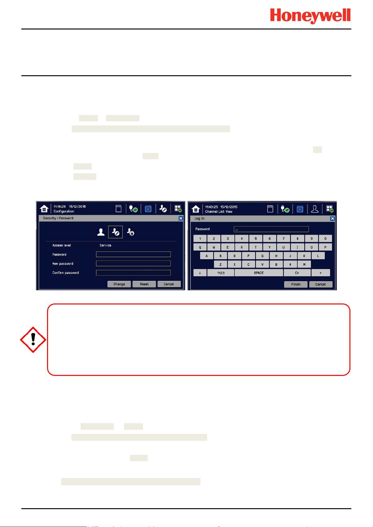
security protocols or the guidelines in this manual.
6.3.4 How To Change a Password
You can only change your own or lower level passwords. The initial default password for all levels is TPPL but it should
always be changed during or immediately after Commissioning.
1) Login as Service or Administrator.
2) Touch Menu icon>Configuration>Security>Password.
3) Touch an access level icon and touch each box to open a keyboard.
4) Input the currently logged in password, the new password, and confirm the new password. (Toggle the [↓↑] key for
upper / lower case letters, and the [?123] key for symbols.
5) Touch [Finish] to close the keyboard before touching the next box.
6) Touch [Change] when finished.
Note: The stored passwords will be replaced with the new passwords so you must also update any written copies.
For security reasons you must change the default Administrator, Service and Operator passwords at the earliest
At the very least you should keep a copy of the Administrator password in a safe place as it cannot be recovered
Careless password management can allow unauthorized access to the system, which may cause safety issues
that are the user's sole responsibility. Honeywell™ will not be liable if any end-user fails to follow established
Commissioning
CAUTION
opportunity and periodically thereafter.
if lost or forgotten.
6.3.5 Forgotten Passwords
The Administrator or Service Engineer can reset low er level p assw or ds but the Administrator password cannot be
changed or reset without inputting the current Administrator password.
To reset a lower level password:
1) Log in as Administrator* or Service.
2) Go to Menu>Configuration>Security>Password.
3) Touch the user to change, then enter your own password, and then enter and confirm the new password.
4) Alternatively you can use the [Reset] button to reset to the default password TPPL, and then allow the user to set
their password as shown above.
* Lost Admin passwords can only be reset by authorised Honeywell Field Service Technicians. See the back page or
select TPPL Menu>Information>Service Contact for details.
MAN0984_Iss 3_02/16 Touchpoint Plus
Pt. No. 3011M5001_3 50 Tec hnical Handbook

Commissioning
6.4
Date, Time and
System Date and Time settings are used by the events log, so you should decide whether to use Local or UTC time.
Using UTC means that you have a global time stamp and you do not have to adjust for daylight saving time.
Note: You should replace the CMOS battery every two years or when the time and date settings are not retained after
power is cycled.
Note: You should regularly check the time and date settings and adjust them if required. To uchp oint Plu s does not adjust
automatically for daylight savings time so it retains a copy of the earlier data if the clock is backdated (e.g. when ending
daylight savings time), which can show as a mismatch in the events log chronol ogy .
6.4.1 How to Set or Change Date, Time and Language Settings
1) Touch the Login icon in the navigation bar and a login prompt will ask for the access level and Password.
2) Login to the Service access level.
3) From the navigation bar select Menu>Configuration>General>Date / Time.
4) Set the date, time and display format as required.
5) Touch [Finish].
6.5 Service Contact Settings
To set the Service contact:
1) Login as Administrator or Service.
2) Touch Menu>Configuration>General>Service Contact.
Language Settings
3) Update the settings with your local service support contact details.
4) Touch [Finish] and return to the Configuration menu.
MAN0984_Iss 3_02/16 Touchpoint Plus
Pt. No. 3011M5001_3 51 Tec hnical Handbook

Commissioning
6.6 Touch Panel Configuration
The Touchscreen can be configured to match local preferences and it can be recalibrated if it does not perform as
expected.
6.6.1 How to Change the Backlight Timeout and Brightness
1) Login as Administrator or Service.
2) Touch the Menu>Configuration>Display.
3) Touch and enter LCD Backlight Timeout and Brightness settings, or touch [Start] to calibrate the Touch Panel (see
below).
4) Touch [Finish] and return to the Configuration menu.
Parameter Name Default Setting Value Range Comment
Backlight time out 30 seconds
(0.5 min)
6.6.2 How to Calibrate the Touch Panel
To calibrate the screen:
1) Login as Administrator or Service.
2) Touch Menu>Configuration>Display.
3) Touch [Start].
4) Follow the instructions on screen, touching each marker as it appears.
5) Touch [Finish] and return to the Configuration menu.
6.7 Latching Alarms
Latched alarms stay active (after the input reading has reverted to the normal range) until acknowledged, whereas
Unlatched alarms are automatically reset when the reading goes back to the normal range.
To set or change latched alarms:
1) Log in as Service.
2) Touch Menu>Configuration>Channel Settings.
0.5 to 10 mins
or
Always On
This is the time that the backlight will remain on after the
Touchscreen is idle.
If a new event occurs, the backlight will come on and will
remain on as long as the event remains unacknowledged.
3) Touch the Input Module to change (circled)…:
MAN0984_Iss 3_02/16 Touchpoint Plus
Pt. No. 3011M5001_3 52 Tec hnical Handbook

Commissioning
4) …to give this window:
5) Touch the Channel you want to change and then touch [Select].
6) Touch the Channel Enable>Enable option:
7) then touch [Next]:
MAN0984_Iss 3_02/16 Touchpoint Plus
Pt. No. 3011M5001_3 53 Tec hnical Handbook
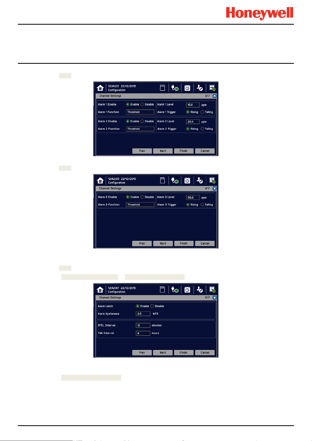
Commissioning
8) Then [Next] again:
9) Then [Next] again:
10) Then [Next] again:
11) Touch Alarm Latch>Enable or Alarm Latch>Disable:
12) Touch Finish>Apply>Update.
13) Repeat to configure another Alarm channel.
MAN0984_Iss 3_02/16 Touchpoint Plus
Pt. No. 3011M5001_3 54 Tec hnical Handbook

Commissioning
6.8 Remote Reset / Acknowledge / Inhibit Switch Options
Select this option if your system has been installed with Remote switches that supplement the local Alarm Acknowledge,
Alarm Reset, or Channel Inhibit options.
1) Confirm whether the remote inhibit switches are normally open circuit or normally closed circuit. (Single stand-alone
switches can be either mode but multiple switches must be normal closed circuit if wired in series and normal open
circuit if wired in parallel.)
2) Login as Service or Administrator.
3) Touch Menu>Configuration>Security>Remote Access.
4) Touch the required [Enable / Disable] options and whether the Remote Inhibit Setting is Normal Open or Normal
Closed.
5) Touch Finish>Close>Close>User Icon>Log Out.
6.9 Data Logging
You should set the Data Logging Interval and Threshold during initial configuration.
Using a 0 %FSD Threshold means that the TPPL will log the gas concentration at the specified intervals without checking
changes in gas concentration. In contrast, a >1 %FSD Threshold setting will ignore fluctuations in low ambient gas
concentrations and only check for rises in gas above the Threshold (i.e. safe) setting.
Leave the Interval setting at 0 seconds if you don’t want to log gas concentration at the configured log interval. However, if
you do want to monitor changes, you should start with a low threshold setting and slowly increase it by trial and error it if
you get too many unnecessary warnings.
Note: A low gas concentration %FSD reading at one sensor only applies to the area immediately surrounding that
sensor, and may not indicate dangerous concentrations elsewhere in the room. Always consider using multiple
sensors at differing heights and locations and allow for sudden draughts that can cause sharp rises in %FSD in
odd places.
Relying on fixed detectors gives insufficient coverage in moving atmospheres, so always take additional safety
measures (e.g. wearing Honeywell personal gas alarms) before entering or working in the monitored location.
6.9.1 To set or change Data Logging:
1) Log in as Administrator or Service.
2) Touch Menu>Configuration>Log Interval & Threshold.
3) Touch a box and enter the details using the touchpad.
4) Touch [Finish].
5) Make other changes or [Log Out].
MAN0984_Iss 3_02/16 Touchpoint Plus
Pt. No. 3011M5001_3 55 Tec hnical Handbook

Commissioning
6.10 TPPL TCP/IP Address
The default TPPL TCP/IP address (for optional Web Interface access) is 192.168.0.100, but you may need to change it if it
conflicts with other items on the network or if the Control Room is monitoring multiple TPPL systems. See Ch.6.11
Network Settings for Web and MODBUS TCP and Ch.6.12 Modbus RTU Settings for further information.
6.11 Network Settings for WEB and MODBUS TCP
TPPL can be installed with the ability to view its status over the Web, and a future upgrade will allow control over the Web.
(See Ch.7.17 Monitoring TPPL via the Optional Web Interfa c e for more deta il s.)
Note: It will be the end user’s sole responsibility to protect the TPPL system from unauthorised access or
tampering.
Note: It is important to ensure that the default IP Address does not clash with other units on your network.
To check or set the IP Address:
1) Log in as Administrator or Service
2) Menu>Configuration>Network>Ethernet
3) Touch a radio button to set the IP acquiring type (DHCP / SIP)
4) Touch the IP Address box to change the address (only if there are network conflicts) and enter the new IP Address
using the onscreen keyboard:
5) Touch [Finish]
6) Touch the Subnet Mask and Gateway boxes (if required), and use the keyboard to enter new values as before
7) Touch [Finish]
8) [Log out]
MAN0984_Iss 3_02/16 Touchpoint Plus
Pt. No. 3011M5001_3 56 Tec hnical Handbook

6.12 Modbus RTU Settings
See the separate Modbus User Guide for instructions on setting up Modbus on a Remote Terminal Unit. You will also
need to know the Host Baud and Parity settings.
To view or change the Modbus Settings in TPPL:
1) Log in as Administrator or Service
2) Menu>Configuration>Network>Modbus RTU
3) Touch the Address box if you want to change the default sett ing
4) Touch the Baud box to change the communication speed to 4800, 9600, or 19200 Baud, then [Select]
5) Touch the radio buttons to change Parity and Databits:
6) Touch [Finish] when done
7) [Log out]
Tip: You can reduce the default Baud if communication is slow or unstable or increase it if you have a really good
connection.
Commissioning
MAN0984_Iss 3_02/16 Touchpoint Plus
Pt. No. 3011M5001_3 57 Tec hnical Handbook

Commissioning
6.13 Commission Input / Output Modules
1) Login as Service or Administrator.
2) Touch Menu> Configuration>Module Control Panel.
3) Touch [Refresh] to check for additional modules (if an expansion unit is connected and switched on).
4) Touch an I/O module (a blue block) and touch [Add]. Touch one of the listed I/O module types.
5) Repeat for other installed I/O modules.
6) To remove a module, select the Module on the screen and then touch [Remove]. To replace it, touch [Replace].
Note: Sky blue blocks show uncommissioned or decommissioned modules.
6.14 Channel Configuration
Note: Administrator or Service level access is required. Please refer to Ch. 7.4 Menu Items and Access Levels for details.
Note: There is no channel calibration reminder, and the user can disable the relevant calibration warning by setting the
calibration interval to zero. (See Ch. 6.14.2 Configuring a Channel and Ch. 6.14.3 Editing a Configured Channel).
6.14.1 Introduction
Individual channels can be configured in tw o w ays – either from the built in sensor catalogue (for Analogue Input modules
only), or by completing a full custom configuration.
When using the sensor catalogue, only the Analogue Channel number and tag must be manually entered and then the
rest of the configuration will be populated automatically when a detector is selec ted from the pre-defined list.
Note: You can always use the sensor catalogue as a starting point and then amend it afterwards (see ‘Ch.6.14.3 Editing a
Configured Channel’ and ‘Ch. 18 Configurable Parameter Reference Guide).
To change any parameter, enter the new value and touch Apply to update the system. The system will then return the
value, which will be displayed on the screen, and the user must touch Update for the settings to take effect. This requires
the user to verify that the correct value has reached the system.
New values can be entered in various ways:
• Free text (i.e. channel tag)
• Numeric keypad
• Check / uncheck a box (i.e. to toggle an alarm between latching and non-latching)
• Select an option by checking a radio button
• Select from a list of available options (i.e. channel number)
The configuration is designed to be simple to follow on the screen. However you can refer to Ch.18 Configurable
Parameter Reference Guide to find detailed definitions of all the parameters, default settings and available ranges.
MAN0984_Iss 3_02/16 Touchpoint Plus
Pt. No. 3011M5001_3 58 Tec hnical Handbook

Commissioning
6.14.2 Configuring a Channel (mA Input and mV Input Channels)
Choose your required configuration method, and follow the on-screen instruction s. Refer to Ch.18 Configurable Parameter
Reference Guide for detailed information on configurable parameters.
Note: You will need to have the required configuration information available before starting this procedure or you risk
having the system timing you out and decommissioning the uncompleted channel and losing all of your unsaved changes.
If you want to configure an indi v idual cha nnel :
1) Login as an Administrator or Service.
2) Touch Menu>Configuration>Channel settings.
3) Touch the required Module type.
4) Touch a required channel and touch [Select].
5) Touch [Enable] for a required chan nel.
6) Touch [Channel Number] and [Enter Channel Tag].
7) Touch a detector name and a sensor type to import all relevant configuration parameters from the Sensor Catalog.
8) Edit the channel parameters.
9) Touch [Finish] if modification of channel settings is complete.
10) Check whether the channel settings are valid before making it take effect.
11) Touch [Apply].
An I/O Module will be set into Configuration State if a configuration update is attempted for any of its channels
Configuration State means that all commissioned channel s on the I/O Module are set into Inhibit state – i.e. the
Changing the detector type, gas type, or mV full scale deflection will reset the input channel calibration data and
input channels will not trigger any alarms and output channels will not execute any actions.
You should consider alternative safety measures when performing these procedures.
CAUTION – CHANGING COMPONENTS
you will get a Calibration Due warning. If this happens you must recalibrate the channel to ensure accurate
readings. See Ch.6.15 Calibrating Input Channels for further informati on.
CAUTION – ALARM INHIBIT
(i.e. Commission Channel or Edit Configuration).
MAN0984_Iss 3_02/16 Touchpoint Plus
Pt. No. 3011M5001_3 59 Tec hnical Handbook

Commissioning
6.14.3 Editing a Configured Channel
Note: There is a 15-minute ‘no-input’ timeout limit, after which you will be logged out and any unsaved changes will be
lost. It may also be necessary to return to the System Setup screen and set the module to normal state.
To edit an already configured channel:
1) Login as an Administrator or Service.
2) Touch Menu>Configuration>Channel settings and then select an I/O module.
3) Touch the required channel.
4) Touch the screen that you want to edit (refer to previous sections of this manual).
5) Enter the required values in the New Value field and tou ch [Finish].
6) Review all parameters are valid and touch [Apply].
7) The system will return the new value; touch [Update] to confirm.
6.14.4 Editing mA Input Channel Settings
1) Log in as Service.
2) Touch Menu>Configuration>Channel Settings.
3) Touch the Input Module you want to change (circl ed) …:
4) …to give this window:
5) Touch the [Channel] you want to change and then touch [Select].
MAN0984_Iss 3_02/16 Touchpoint Plus
Pt. No. 3011M5001_3 60 Tec hnical Handbook

Commissioning
6) Touch any settings you want to change, then scroll through and touch your choices, and touch [Select] to close the
window:
Please refer to Ch.15 Compatible Sensors for a list of
available detectors.
You can also use the TPPL Sensor Catalog to select
listed gases, or you can enter ‘User gas’ details if your
gas is not listed.
Please refer to Ch. 8.6 How to Update the Sensor
Catalogue for further informat i on.
7) Then touch [Next] to see these settings inserted ( use [Prev] if you want to amend them):
MAN0984_Iss 3_02/16 Touchpoint Plus
Pt. No. 3011M5001_3 61 Tec hnical Handbook

Commissioning
8) Then touch [Next] again to change more settings:
Note: Touch the [Alarm Function] boxes to open a dialog box for Threshold, STEL or TWA choices.
9) Then touch [Next] again to change more settings:
10) Then touch [Next] again to change more settings:
Note: The default TWA Interval is based on an average 8-hour working shift so that the next shift always starts the plot
with zero exposure. You should change the hours if your regular shift pattern is lon ger or shor ter ( e.g. 6 / 12 / 24 hrs etc.).
MAN0984_Iss 3_02/16 Touchpoint Plus
Pt. No. 3011M5001_3 62 Tec hnical Handbook

Commissioning
11) Touch and enter the [Calibration Interval] and the [Span Gas Concentration] that was used for First Span, then select
[Next]:
12) Touch and change the following [Channel Settings]:
Note: This Window’s options tell the system what input values are relevant and actionable. These values shall only be
changed by Honeywell Authorised personnel or by qualified personnel trained in accordance with this manual.
Note: [Inhibit Timeout] is a failsafe timeout in case the User forgets to reset a local inhibit. It does not affect Remote Inhibit
switches that are either on or off (e.g. key switches).
13) Touch Finish>Apply>Update.
14) Repeat to configure other Alarm channels.
Note: You will have to redo an y unsaved change s if the syst em reverts to an earlier window due to inactivity.
MAN0984_Iss 3_02/16 Touchpoint Plus
Pt. No. 3011M5001_3 63 Tec hnical Handbook

Commissioning
6.14.5 Editing mV Input Channel Settings
1) Log in as Service.
2) Touch Menu>Configuration>Channel Settings.
3) Touch the Input Module to change (circled)…:
4) …to give this window:
5) Touch the [Channel] to change and then touch [Select] to give this window:
MAN0984_Iss 3_02/16 Touchpoint Plus
Pt. No. 3011M5001_3 64 Tec hnical Handbook

Commissioning
6) Touch the required settings, change details and touch [Select]:
Please refer to Ch.15 Compatible Sensors for a list of
available detectors.
You can also use the TPPL Sensor Catalog to select
listed gases, or you can enter ‘User gas’ details if your
gas is not listed.
Please refer to Ch. 8.6 How to Update the Sensor
Catalogue for further informat i on.
Note: The Target Gas Type is automatically entered by your choice of Sensor Type.
Note: The Sensor Type gases will vary with different types of Detectors. Gases listed with a ‘-2’ suffix are compliant with
EN 60079-20-1 LEL levels.
Note: Sensors must be recalibrated when selecting a new target gas.
Note: mV-bridge sensors are not suitable for use in oxygen enriched atmospheres (e.g. >21 %v/v) as the bridge bead will
be too reactive, leading to false readings and premature burn-out. However Oxygen deficient atmospheres (e.g. <10 %v/v)
may suppress sensor output because there will be insufficient bead reaction to change the bridge’s resistanc e readin g.
MAN0984_Iss 3_02/16 Touchpoint Plus
Pt. No. 3011M5001_3 65 Tec hnical Handbook

Commissioning
6.14.6 Editing Relay Output Channel Settings
Prior to starting you should have completed configuring or editing all of the required input channels.
1) Login as an Administrator or Service.
2) Touch Menu>Configuration>Channel settings.
3) Touch the required Relay Output Module (circled):
4) To get this window:
5) Touch a channel to commission or edit and touch [Select].
6) Touch the buttons and boxes to make changes as required:
MAN0984_Iss 3_02/16 Touchpoint Plus
Pt. No. 3011M5001_3 66 Tec hnical Handbook

Commissioning
7) Touch [Next].
8) Choose Count Reduction options. This option allows you to ignore faulty or inhibited detectors for Vote Count
purposes (See also 10 below):
‘Voting’ is where an installation requires confirmation from at least 2 detectors before it triggers a response.
‘Vote Count Reduction’ is where the controller can be told to ignore voting channels that are in Fault mode or Inhibit
mode or both, and will trigger an event when one or more detectors (not in fault or inhibit) are triggered.
Non-voting detectors are not affected by Vote Count Reduction.
9) Touch [Next] and then choose Inputs (Alarms A1, A2 & A3, Fault, Inhibit & Warnings) to auto-populate all the
available channels. Scroll down to see further channels and selectively un-tick if required.
10) Touch and enter Vote Count numbers if required (see box above).
11) Touch [Finish].
MAN0984_Iss 3_02/16 Touchpoint Plus
Pt. No. 3011M5001_3 67 Tec hnical Handbook

Commissioning
12) Review the settings, scrolling down to see them all:
13) If happy with the settings, touch [Apply]. Wait for the changes to be made.
14) Review again and select [Update].
15) Repeat all to Commission or edit further relay channels.
6.15 Calibrating Input Channels
MAN0984_Iss 3_02/16 Touchpoint Plus
Pt. No. 3011M5001_3 68 Tec hnical Handbook
Gas readings may be generated during this procedure. Disable or inhibit any operations or actions that may
For catalytic bead type detectors, the Analogue Input Modules form part of the measuring circuit. Therefore all
commissioned mV channels remain in Inhi bit stat e until they ar e calibr ate d.
You should consider alternative safety measures when performing these procedures.
CAUTION – ALARM INHIBIT
result from gas readings before starting this test.

Commissioning
6.15.1 Adjusting the mV Sensor Baseline
It is important to select [First Span] when calibrating a new or replacement sensor for the first time, and [Span] for all
calibrations thereafter.
It is important to select [Adjust mV Bas eli ne] when calibrating a new or replacement sensor for the first time, and [Span]
for all calibrations thereafter. This also applies when either the detector type or sensor type is changed during channel
configuration, even though the sensor itself remains the same.
Doing this procedure corr e ctly allows you a time window in which to safely organise the replace ment of nearly
To adjust the mV Sensor Baseline:
1) Replace the catalytic bead sensor in accordance with its’ user manual.
2) Check the mV sensor wiring is undamaged and correctly connected.
3) Perform the next check under clean air.
4) Login as Administrator or Service.
5) Touch Menu>Maintenance>Adjust mV Baseline and select a mV input channel.
Doing it incorrectly may result in a spent sensor with incapable gas detection.
CAUTION
spent catalytic bead sensors.
6) Touch [Start].
7) Check mV sensor type setting is correct.
8) Carry out the sensor calibration as shown in the next section (the mV input channel will be automatically inhibited
during this procedure).
6.15.2 Calibrating a mV Input Channel
To calibrate a mV input channel, follow the procedure below in combination with the relevant instructions in the sensor
manual.
This procedure requires 2 people in radio or telephone contact.
Only trained technicians are authorized to carry out sensor calibration.
Caution: Ensure that any relay operated devices (drenchers, repeater alarms, etc.) are inhibited before starting this test.
1) Log in as Service.
2) Touch Menu>Maintenance>Gas Calibration. Touch the channel to be calibrated followed by [Select].
MAN0984_Iss 3_02/16 Touchpoint Plus
Pt. No. 3011M5001_3 69 Tec hnical Handbook

Commissioning
3) Touch [Start] while applying clean air to the sensor.
4) Wait until the sensor readin g becomes stable .
5) Confirm the zero calibration reading and then touch [Next].
6) Touch [Target concentration.] and enter the target concentration of your span gas (%LEL) followed by [Finish].
7) Touch First calibration to toggle it on or off as appropriate. Failing to carry out First calibration on new sensors may
falsely reduce their useful life, while carrying it out on used sensors may lead to unexpected sensor failures.
8) When ready, touch [Start] and apply your span gas to the sensor.
9) Wait until the sensor readin g becomes stable .
10) Confirm that the gas reading is correct and touch [Finish]:
11) Remove the span gas from the sensor, and choose whether or not to calibrate another channel.
MAN0984_Iss 3_02/16 Touchpoint Plus
Pt. No. 3011M5001_3 70 Tec hnical Handbook

6.15.3 Calibrating a mA Input Channel
To calibrate a mA input channel, follow the procedure below in combination with the relevant instructions in the sensor
manual.
This procedure requires 2 people in radio or telephone contact.
Only trained technicians are authorized to carry out sensor calibration.
Where the sensor or transmitter has the facility, the mA loop should always be calibrated by forcing signal levels
at the sensor / transmitter. Any gas calibration required must be carried out at the field device according to the
The Touchpoint Plus controller calibration should not be used to adjust for deficiencies in the sensor / transmitter
Caution: Ensure that any relay operated devices (drenchers, repeater alarms, etc.) are inhibited before starting this test.
The span gas should normally be air at 20.9% v/v Oxygen if the O
force mA function.
The Touchpoint Plus controller calibration should not be used to correct deficiencies in the sensor calibration; instead
carry out a gas calibration at the sensor according to the manufacturer’s instructions.
To calibrate the mA loop of an input channel, please follow the procedure below in combination with the relevant
instructions in the sensor manual.
1) Log in as Service.
2) Touch Menu>Maintenance>Gas Calibration. Touch the channel to be calibrated followed by [Select].
gas calibration. Failure to observe this can result in significant accuracy errors.
Commissioning
WARNING
manufacturer’s instructions.
sensor is not being used with a transmitter that has a
2
3) Touch [Start] while applying clean air to the sensor.
4) Wait until the sensor readin g becomes stable .
MAN0984_Iss 3_02/16 Touchpoint Plus
Pt. No. 3011M5001_3 71 Tec hnical Handbook

Commissioning
5) Confirm the zero calibration reading and then touch [Next].
6) Touch [Target Conc.] and enter the target concentration of your span gas (ppm) followed by [Finish].
7) When ready touch [Start] and apply your span gas to the sensor.
8) Wait until the sensor readin g becomes stable .
9) Confirm that the gas reading is correct and touch [Finish]:
10) Remove the span gas from the sensor, and choose whether or not to calibrate another channel.
MAN0984_Iss 3_02/16 Touchpoint Plus
Pt. No. 3011M5001_3 72 Tec hnical Handbook

Commissioning
6.16 Backing Up the Configuration Settings
It is recommended you back up the TPPL configuration once commissioning is completed or w hen any software, modules
or settings are changed. Alternative safety arrangements should be in place during this procedure.
Power should always be off and isolated before opening the access door, and the door should always be closed
Opening the enclosure will expose live high-voltage terminals that may remain live for a time after power is
switched off. Do not touch these terminals or the Earth (Ground) bar as they can cause electric shock and burns.
6.16.1 How to Back Up the Configuration:
1) Complete and save all configuration changes.
2) Touch Menu>Maintenance>SD Card>Eject>
3) Touch Close>Menu>Maintenance>Power-off>Yes
4) Switch off and Isolate Power.
5) Open the access door and locate the SD card slot (see Fig.10 item 2).
6) Temporarily replace the installed SD Card with an empty 2 to 32 GB (FAT32) standard SD Card.
7) Close the access door, restart the system and wait for it to stabilise.
8) Check the SD Card status by touching on either the SD Card or Power Icons:
9) Log in as Administrator or Service.
10) Touch Menu>Configuration>Config Manager>Export.
and secured during normal operation.
WARNING
11) Enter a file name for the back-up configuration file and touch [Finish].
12) Touch [Export] to continue. The backup may take several minutes, and progress is shown on screen.
13) When backup is completed, touch Menu>Maintenance>SD Card>Eject>
14) Touch Menu>Maintenance>Power-off>Yes.
15) Switch off and Isolate Power.
16) Open the access door.
17) Replace the Backup SD card with the original card or a new card t hat has sufficient space to record event data.
18) Close the enclosure door and tighten the two handle security screws.
19) Switch power on and return the system to normal operation. Touch the SD Card Icon to confirm the SD card status.
20) Transfer the backup data to a dated folder on a PC or digital device for safekeeping. The Configuration backup file is
stored on the SD Card in \\CFG\TPP_CFG.bin
21) You can reuse the card once the backup file has been transferred.
6.16.2 How to Restore the Configuration
To restore a configuration, you must first copy the stored file [Your PC] \\CFG\TPP_CFG.bin to the root
directory of an empty SD card (FAT32), and then an Administrator must follow the reverse process of backing up, i.e.
use [Import] instead of [Export].
Note: \\CFG\TPP_CFG.bin must not be inside a folder on the SD card.
Note: Before attempting to restore from a saved configuration you must ensure that the current status is exactly the same
as it was when the backup file was exported. In other words the module installation status and commissioning status must
be exactly the same or the system will not import the configuration data.
MAN0984_Iss 3_02/16 Touchpoint Plus
Pt. No. 3011M5001_3 73 Tec hnical Handbook

Commissioning
This page deliberately blank.
MAN0984_Iss 3_02/16 Touchpoint Plus
Pt. No. 3011M5001_3 74 Tec hnical Handbook

Operating Instructions
Take alternative site safety precautions while power is off.
Local Accept /
Reset Button
Chapter 7. Touchpoint Plus User Guide
Opening the enclosure may expose live electrical circuits. Touching exposed terminals or wires may cause death
or serious injury. Always turn off and isolate the system before opening the door. Do not switch back on until the
The TPPL Touchscreen is the primary control and viewing method but there is also an optional Web Interface that
currently allows remote viewing only (see Ch.7.17 Monitoring TPPL via the Optional Web Interface for more details).
door is reclosed and secured. Do not operate TPPL with the door insecure.
7.1 User Interface General
Figure 48. Touchpoint Plus Controller User Interface
WARNING
The User Interface panel (shown above) has:
• A colour Touch screen for normal system operation, maintenance and configuration
• Power, Alarm / Fault and Inhibit state LEDs
• Active Channel (01 to 08) status indicators (Ch. 07 is not commissioned in this example)
• Active Expansion Channel (09 to 16) status indicators (not commissio ned abov e)
• Accept* / Reset membrane button (arrowed above)
• Integral Alarm Buzzer (Left side)
*The membrane button acknowledges and silences active alarms and resets latched alarms, depending on the situation
and how long it is pressed. See Ch.7.8 Responding to Alarms for further information.
Further System Interfaces consist of:
• Remote inhibit and remote reset terminals in the Main module
• One fixed relay and two configurable relays in the Main Module for system Failure, Alarm and Inhibit
• Three dedicated alarm outputs for visual and audio alarms
• An SD Card slot for data logging and firmware/software updates
• An optional expansion unit with optional dual input module (mV & mA)
• Optional remote Web Interface networking via RS485 port
• Optional remote Modbus TCP/IP via hard-wired terminal
MAN0984_Iss 3_02/16 Touchpoint Plus
Pt. No. 3011M5001_3 75 Tec hnical Handbook

7.2 Touchscreen
The Touchscreen is touch only; it has no swipe or pinch gestures.
The Touchscreen has four access levels: View mode is available to all users while Configuration, Maintenance and
System Test functions are password protected. (See Ch.7.4 Menu Items and Access Levels for further information.)
There are only three passworded accounts: Administrator, Service and Operator, and their passwords must be carefully
guarded.
Lost passwords can only be replaced by someone higher which, in the case of the Administrator, will be a Honeywell
representative.
Password holders should be assigned to one access level only.
7.3 Switching On and Off
Before switching power on, ensure that the system has been commissioned or that a qualified person has checked that
the wiring is safe and conforms to local regulations. Also check that the battery isolator switches are ‘On’ and that an SD
Card is fitted. Check that the optional expansion unit battery switches are on too.
Switch on power at the Isolator switch and wait for the system to initialise. (The system start up sequence may last for up
to 5 minutes depending on the number of channels in use.)
TPPL will first display the auto-scrolling Input screen, indicating the current status of the system. The Channel List View is
shown below. The screenshot shows installed sensors but it may be blank depending on your system status:
You can alter the screen views or gain further information by touching the icons shown below:
Toggle to select screen layout
SD Card Status Good
SD Card Status Fault
External mains power is connected.
Touch for status
External power is not connected.
Touch for status
Event History (changes colour to show
fault, inhibit or alarm)
Further Menu Options
Operating Instructions
Table 13. Home Screen Menu Icons
Admin Logged in
Service Logged in
Operator Logged in
No one Logged in
Toggle auto-scroll on and off
Scroll up when auto-scr oll dis a bled
Scroll down when auto-scroll disable d
MAN0984_Iss 3_02/16 Touchpoint Plus
Pt. No. 3011M5001_3 76 Tec hnical Handbook

Operating Instructions
7.4 Menu Items and Access Levels
The table below details the menu items and access levels for the User Interface. The password hierarchy is Administrator,
then Service, then Operator. Broadly speaking, the Administrator can do everything, the Service Engineer can edit
channel configuration and do maintenance and calibration, and the Operator can view, acknowledge and reset events.
(Viewing basic System Information and Status does not require a password.)
A user can log in by touching the log in icon, selecting an access level and then inputting a valid password.
Note: Default Authentication timeout follows 15 minutes of inactivity. For security reasons do not leave the Touchscreen
unattended while logged in.
There are two kinds of timeout in menu mode. One is ‘menu timeout’ and the other is ‘authentication time out’.
With ‘menu timeout’, the display will change to a higher menu and then back to the Channel Status screen if there is no
touch input for a pre-set time. The default menu timeout is 90 seconds, but this can be changed using menu options
Configuration>General>Timeout.
For security reasons ‘authentication timeout’ will log you out automatically when there is no Touchscreen activity during
the set time. Changes may be lost and the user will have to log in again.
Items with a clock symbol timeout after 15 minutes of inactivity.
Key: = Allowed, = Denied, = Fixed timeout.
= sub-menu, = sub-sub-menu
Menu Item Admin. Service Operator Others
Login
Menu Home
Information
System Info
Summary Info
Software Info
Parameter Info
Event History
Filter View
Export History
Trend/Plot
Channel Info
Board Info
Relay Status
Additional Status
Service Contract
Event History
Channel View Home
List View
Tile View
Summary View
Output View
Configuration
MAN0984_Iss 3_02/16 Touchpoint Plus
Pt. No. 3011M5001_3 77 Tec hnical Handbook

Operating Instructions
Menu Item Admin. Service Operator Others
Channel Settings
mA Input Channel
mV Input Channel
mA Output Channel
Relay Channel
Module Control Panel
General
Date / Time
Language
Service Contract
Home Settings
Timeout Setting
Log Interval and Threshold
Display Screen
Outputs
Dedicated Alarm Contacts
Buzzer Options
Security
Password
Remote Access (Buttons)
Config Manager
Import
Export
Network
Ethernet
Modbus RTU
Maintenance
Reset Alarms / Faults
Reset All Peaks
Gas Calibration
Adjust mV Baseline
Service Mode
Electronic Adjustment
Safety Function
Reset to Defaults
Update System
Software
Language
MAN0984_Iss 3_02/16 Touchpoint Plus
Pt. No. 3011M5001_3 78 Tec hnical Handbook

Operating Instructions
Menu Item Admin. Service Operator Others
Sensor Catalogue
Module Data
SD Card
Eject
Format
Power Off
System Test
Force Relay
Force 4–20 mA
Relay C & E Matrix
Dedicated Alarm Contacts
Table 14. User / Component Matrix
7.4.1 Navigation – Active Access Level Icons
You must enter a valid password to access the menu items listed above. (See Ch.6.3 Logging In/Out.)
The silhouette icon shows who is logged in. Touch the icon to log in / out, or to change to a higher access level:
Note: The system will log you out after a set period of inactivity. (The default authent i cat ion t imeo ut is 15 minut es, but this
can be changed in system settings.)
No one is logged in
Operator is logged in
Service engineer is logged in
Administrator is logged in
7.5 SD Card Usage
The SD card is used to store the system event history. Touchpoint Plus logs all events and all changes to input readings.
A notification will be given when the SD card has less than 50 Mb of space remaining. If the card is not replaced with an
empty one, or if space is not freed up, a further notification will be given when it is full and data is being overwritten. The
SD card icon also changes to yellow to indicate that there is a fault with data saving.
The Touchpoint Plus accepts standard size SD cards of 2 to 32 GB (FAT32). SD cards must be formatted on first
insertion.
7.5.1 Checking the Capacity of the SD Card
There are three ways to check the SD Card size and remaining space:
• Touch Menu>Information>Additional Status.
• Touch the SD Card icon in the menu toolbar (no icon = no SD Card, yellow icon = needs checking).
• Touch the Power Supply icon in the menu toolbar.
MAN0984_Iss 3_02/16 Touchpoint Plus
Pt. No. 3011M5001_3 79 Tec hnical Handbook

Operating Instructions
Take alternative site safety precautions while power is off.
7.5.2 Inserting or Replacing SD Cards
SD Cards must be unlocked to allow read/write. They must be formatted by TPPL only, and they should be used for TPPL data
only. Stored data can be transferred or copied to a PC via a Card Reader and the card reused, but care must be taken not to
overwrite previously transferred data files held on the PC. A reliable backup system should be used if data retention is important.
Transferred data may be imported into spreadsheets or DBs for ease of handling / printing, but you should check the
number of spreadsheet lines available as some software may be limited to 65000 entries per sheet.
Note: Incorrectly removing or replacing an SD card may result in data loss or corruption.
Opening the enclosure may expose live electrical circuits. Touching exposed terminals or wires may cause death
or serious injury. Always turn off and isolate the system before opening the door. Do not switch back on until the
To Insert or Replace an SD Card:
1) Log in as Admin or Service.
2) Touch Menu>Maintenance>SD Card>Eject>
door is reclosed and secured. Do not operate TPPL with the door insecure.
WARNING
3) Touch Close>Menu>Maintenance>Power-off>Yes
4) Switch off and Isolate Power.
5) Open the access door and locate the SD card slot (see Fig. 10 item 2).
6) Insert or replace the card in the SD card slot.
7) Close the access door, restart the system and wait for it to stabilise.
8) Check the SD Card status by touching on either the SD Card or Power Icons:
9) If the SD Card is new, full or has a fault, log in as Admin or Service.
10) Touch Menu>Maintenance>SD Card>Format>Yes
11) Close the window and log out when finished.
12) Re-check the SD Card status by touching on either the SD Card or Power Icons again.
Formatting the SD card will erase all existing data, and TPPL has no selective delete or file recovery function.
Note: The SD Card must remain inserted during normal system
to a few minutes of events.
MAN0984_Iss 3_02/16 Touchpoint Plus
Pt. No. 3011M5001_3 80 Tec hnical Handbook
When the card is full
CAUTION
operation as the on-board flash memory is limited
it
should either be replaced or space freed up
to avoid data loss.

7.6
Normal Operation (Safety
During normal operation:
• The Touchpoint Plus system will collect sensor data every 250 ms from its Input / Output modules.
• The Cause and Effect matrix will be evaluated every 250 ms, and commands sent accordingly to the appropriate
output channels. System response time is ≤1 s.
• Any change in status of an I/O channel will be reported to the User Interface and logged in the event history.
• Events (Alarms, Faults, Inhibits, etc.) will be reported to the User Interface and logged in the event history.
• Any fault within the system will activate the System Fault relay.
• Any failure of the safety function i.e. due to major fault or power loss will activate the System Failure relay.
7.7 Operating Overview
See (or print) Ch.16
7.7.1 Touchscreen
The colour Touchscreen is activated using a finger or a soft stylus (only). Do not use sharp or abrasive objects as they
may cause irreparable damage.
All interactions are single tap (no gestures or swipes). Some actions open a new Window; depending on the window type,
they can be closed by touching the X or [Cancel] button, or by touching the [Ho me / View ] button.
Icon
Operating Instructions
Functions)
Glossary
for easy reference.
7.7.2
User Interface
Scr
een
The icons in the navigation toolbar are used to toggle through the User Interface options, as shown in the tables below.
Alarm Event Fault Event Warning Event Inhibit Event
Channel List View
Channel Tile View
Channel Summary View
Output Channel List View
Table 15. Home Screen Icons
Notes:
• Flashing Colour – New Events
• Steady Colour – Acknowledged Events
• Channel List View – Display shows up to six inputs and events with automatic or manual scrolling.
• Channel Tile View – Display shows up to eight inputs and events.
• Channel Summary View – Display shows total counts for alarm 1, alarm 2, alarm 3, fault, warning and inhibits.
• Output Channel List View – Display shows up to eight outputs and events.
Events flash until acknowledged, and they stay coloured until the causative event is cleared / reset.
Touch any colour, channel or event if you want to see more information. You can also touch a filter icon (see below) to
show only items in that colour band, which is useful when you have multiple events demanding attention.
Manual Scrolling Toggle (the list and all events
can be manually scrolled)
Auto Scrolling Toggle (active events are locked
at the top of the list, other events scroll down)
Scroll the list up
Scroll the list down
MAN0984_Iss 3_02/16 Touchpoint Plus
Pt. No. 3011M5001_3 81 Tec hnical Handbook

Operating Instructions
Alarm Filter
Fault Filter
Inhibit Filter
Warning Filter
Filter Information
Filter Refresh
Filters only show during active events but you can use them to instantly filter multiple events for clarity.
History Information
Alarm History
Fault History
Inhibit History
Warning History
Toggle View
MAN0984_Iss 3_02/16 Touchpoint Plus
Pt. No. 3011M5001_3 82 Tec hnical Handbook

Operating Instructions
7.7.3 Navigating the Channel Detail Screens.
Touch an individual channel or item to display more details
Please see Ch.16 Icon Glossary for further information.
:
MAN0984_Iss 3_02/16 Touchpoint Plus
Pt. No. 3011M5001_3 83 Tec hnical Handbook

Operating Instructions
6.6.3 Navigation – Active
You can change the list type by touching a filter from one of the Tile views, and you can export the events to the SD card
by touching History>Export Event
Note: The History Information icon is the colour of the highest (uncleared) risk event.
Events and Filtering
MAN0984_Iss 3_02/16 Touchpoint Plus
Pt. No. 3011M5001_3 84 Tec hnical Handbook

7.7.4 Navigation – Menu
User must have the appropriate access level password to enter Maintenance, Configuration and System Test options.
Note: The system will log out after a defined period of inactivity.
(The default password authentication timeout is 15 (15 – 100) minutes and the Menu Timeout is 90 (5 – 100) seconds, but
these can be changed in Configuration>General>Timeout if required.)
Operating Instructions
MAN0984_Iss 3_02/16 Touchpoint Plus
Pt. No. 3011M5001_3 85 Tec hnical Handbook

Operating Instructions
7.8 Responding to Alarms
7.8.1
View Active
Active alarms can be viewed:
1) At the Input screen, touch the red filter icon to display a list of the active Alarms, starting with the most recent event.
2) Unacknowledged alarms will flash; acknowledged ones will stay on.
3) Touch any alarm to view more information.
Note: The display will show the channel ID location tag and a high priority alarm level will be shown If more than one
alarm level has been triggered on the same channel.
Alarms
7.8.2
Accept or Acknowledge
Always check that emergency evacuation and roll-call is completed before silencing the alarms.
To acknowledge an alarm, log in and press the button for >1 second, which will:
• silence the alarm
• stop the channels, LEDs and icons flashing
• acknowledge all active events except Faults
Note: Check for new alarms if the sounder restarts after you have acknowledged it.
Note: If a Relay Output channel has the Alarm Update function enabled, the alarm will be ignored for the Cause and
Effect matrix once it is acknowledged.
an Active
Alarm
MAN0984_Iss 3_02/16 Touchpoint Plus
Pt. No. 3011M5001_3 86 Tec hnical Handbook

has been confirmed to be safe or has been adequately ventilated.
7.8.3
Reset a Latched
A latched alarm is one that cannot automatically reset itself when the triggering event has cleared.
Note: Operator or higher access level is required
A latched alarm can be reset in three ways:
1) By logging in and pressing the button for >3 seconds. This will reset ALL latched alarms, faults and warnings,
2) By logging in and selecting Menu>Maintenance>Reset alarms/Faults. This will reset all latched events
3) By holding the Remote reset switch for >3 seconds. TPPL has the option of adding a remote acknowledge / reset
Operating Instructions
Alarm
provided that the triggering event has cleared. It will also reset any latched relay outputs.
for the channel, provided that the input signal has returned to Normal status.
switch up to 500 m away from the Controller. The remote reset switch does not require a login so a key-lockable
switch should be used to prevent unauthorised access.
WARNING
A gas detector may indicate that the gas concentration in its vicinity has dropped to a safe level, but this does not
mean that a dangerous atmosphere doesn’t persist elsewhere in that area. Do not reset the alarms until the area
7.9
Event Information
7.9.1
Viewing Event
Detailed information about active events can be viewed in several ways:
• by touching the actual event to show detailed information about that channel.
• by touching one of the available filter icons on the bottom toolbar. The screen will then show a list of only the chosen
type of active events, and each event can be touched to show detailed information about that channel.
• by touching the icon to change the view layout (not all screens have filter icons).
Information
7.9.2 Accepting / Acknowledging Active Events
Note: Accept and Acknowledge have the same meaning in this context, but neither action will reset latched events.
Active events can be acknowledged by logging in and pressing the button for >1 second. This will acknowledge ALL
active events and the flashing will stop.
MAN0984_Iss 3_02/16 Touchpoint Plus
Pt. No. 3011M5001_3 87 Tec hnical Handbook

Operating Instructions
7.9.3
Resetting Latched Events
Note: Password access is required.
Acknowledged latched events can be reset in three ways:
1) By logging in and pressing the button for >3 seconds. This will reset ALL latched alarms, faults and warnings,
provided that the event has cleared. It will also reset any latched relay outputs.
2) By logging in and selecting Menu>Maintenance>Reset Alarms/Faults. This will reset all latched events,
provided that the input signal has returned to Normal / within tolerance.
3) By holding the Remote reset switch for >3 seconds. TPPL has the option of adding a remote acknowledge / reset
switch up to 500 m away from the Controller. The remote reset switch does not require a login so a key-lockable
switch should be used to prevent unauthorised access.
7.10
Inhibiting Channels
Note: Service or higher access level is required.
7.10.1 To Inhibit Input Channels:
1) Log in as Administrator or Service
2) Touch a channel, then touch the inhibit icon: and then touch [Yes]
3) Or use a Remote Inhibit input (key-locking) switch.
7.10.2 To Clear Inhibits:
1) Log in as Administrator or Service
2) Touch an inhibited channel, th en touch the inhibit icon: and then touch [Yes]
Note: An auto-inhibit cannot be cleared manually. Auto-inhibits may occur during calibration or warm-up, when a
transmitter is signalling Inhibit, or when an Inhibit delay time is running.
7.10.3 To Change Inhibit Timeouts
1) Log in as Administrator or Service
2) Touch a channel, then touch the Settings icon:
3) Touch [Next] repeatedly until you reach page 7/7, as shown below:
4) Touch the chosen value, enter a new value, and touch [Finish]>[Finish]>[Apply]
Please see Ch.16 Icon Glossary for further information.
MAN0984_Iss 3_02/16 Touchpoint Plus
Pt. No. 3011M5001_3 88 Tec hnical Handbook

Operating Instructions
7.11
Viewing Input Channels and Input
From the Input screen, toggle the icon between Channel Tile>Channel Summary>Channel Output.
1) From the Input screen, select Channel List or Channel Tile.
2) A list of all input channels is shown in order of channel ID. The channel ID, gas name, status, min/max peak gas
concentration and current reading will be shown.
3) The list can be filtered by status – Alarm, Fault, Inhibit, Warning or All.
4) Touch a channel and the Channel detail (left below) screen will appear. Depending on access level, a number of
options will be shown (see Ch.16 Icon Glossary for Icon names):
Details
Function Icon Access Level Comment
Shows detailed information about the channel including Custom ID,
Channel Detail — Viewer
Calibration
Channel Settings
Peak reset
Trend / Plot
Inhibit
Channel location
Trend Graph
Service Option to calibrate the channel.
Service Change the input channel settings.
Service Reset peak reading of the channel.
Viewer Shows the Trend / Plot.
Service
Viewer
Viewer
sensor and gas name, gas reading, configured alarms and alarm
levels.
Inhibits the channel. On an inhibited channel, this option is Clear
Inhibit. See Normal Operation, Inhibit for more information.
Shows the physical position of the I/O Module and channel (see
pictures above).
Shows the trend graph for the channel. See Normal Operation, View
Trend Graph for more information.
MAN0984_Iss 3_02/16 Touchpoint Plus
Pt. No. 3011M5001_3 89 Tec hnical Handbook
Viewer Scroll Left, Right, Up, Down.

Operating Instructions
7.12
Viewing Output
From the Input screen, toggle the Home icon between Channel Tile>Channel Summary>Channel
Output.
1) From the Input screen, select Channel List or Channel Tile.
2) A list of all output channels is shown in order of channel ID. The channel ID, location tag and status are shown.
3) The list can be filtered by status – Fault, Inhibit, Warning or All.
4) Touch a channel and the Channel detail screen will appear. Depending on access level, a number of options will be
shown:
Function Icon Access Level Comment
Channels
Channel configuration
Linked input Channel Nr.
Service
Viewer
Change the output channel configuratio ns: Inhibit, Fault, Warning,
and Over-range output level
Display an output channel number that is mapped to the terminal
number
MAN0984_Iss 3_02/16 Touchpoint Plus
Pt. No. 3011M5001_3 90 Tec hnical Handbook

7.13
Viewing the Trend
The Trend graph is drawn using one minute average readings so it is not suited to viewing short-term signal fluctuations.
To view the graph:
1) Touch the Menu Icon>Information>Trend / Plot.
2) Touch the required channel, and then touch [Select].
3) Select the required Data Range (1/2/4/8 hours) and then touch Plot. (Alarm Threshold is shown by default.)
4) The trend graph will be displayed. Use the arrows to move backwards or forwards in time; use the X or [Cancel] to
exit.
Note: The Touchpoint Plus Trend / Plot will retain up to the latest 8 hours of data but will be cleared after a power reset.
Note: Touchpoint Plus does not adjust automatically for daylight savings time but it will retain a backup of the earlier data
if the system clock is backdated (e.g. when ending daylight savings time).
Operating Instructions
Graph
MAN0984_Iss 3_02/16 Touchpoint Plus
Pt. No. 3011M5001_3 91 Tec hnical Handbook

Operating Instructions
7.14 Viewing and Exporting Event History
The event history for the complete system can be viewed in date order (latest first). The history can be filtered by Alarm,
Fault, Inhibit, or Warning.
7.14.1 To View the Event History:
Touch Menu>Information>Event History, then touch the Filter icon of choice or scroll through the list.
Note: Touchpoint Plus does not adjust automatically for daylight savings time so it will retain a backup of the earlier data if
the clock is backdated (e.g. when ending daylight savings time).
Event data is automatically saved to an installed SD card. The event history data can also be exported to the SD card on
demand.
7.14.2 To Export the Event History:
First touch the SD Card icon to ensure that you have sufficient empty space on the SD card.
Touch Menu>Information>Event History. Select the event (use filters if there are too many shown) and touch
Export Event.
Note: Microsoft Excel 2003 is limited to a maximum of 65,526 entries. If the report is larger than this a ‘file not loaded
completely’ message may be generated. Microsoft Excel 2010 has a much larger capacity that should be sufficient for all
Touchpoint Plus generated reports.
Note: Touchpoint Plus does not adjust automatically for daylight savings time so TPPL will retain a backup of the earlier
data if the clock is backdated (i.e. when ending daylight savings time).
7.15 Accessing the System Information and Service Contact Details
Touch Menu>Information>System information to view details about the Firmware, Software and serial
numbers.
Touch Menu>Information>Service Contact or see the back page for details of how to access technical
support.
7.16 System State and System Failure Relays
The Main Module has three relays (30 VDC or 250 VAC, both 1.7 A):
• One or both System State relays can activate if there is any active alarm, fault, warning or inhibit in the system (if
configured).
• The System Failure relay can activate if the safety function of the system is not operating, for example due to a major
fault or power loss.
MAN0984_Iss 3_02/16 Touchpoint Plus
Pt. No. 3011M5001_3 92 Tec hnical Handbook
 Loading...