

Before Installation
1.
Install
TP975A
with job drawings.
and B Diffuser Thermostat in accordance
Installation
TP975A
and B
Diffuser
Thermostat
Installation Instructions
Mount units with fixed minimum outdoor air dampers such
2.
that the thermostat does not see any outdoor air.
General
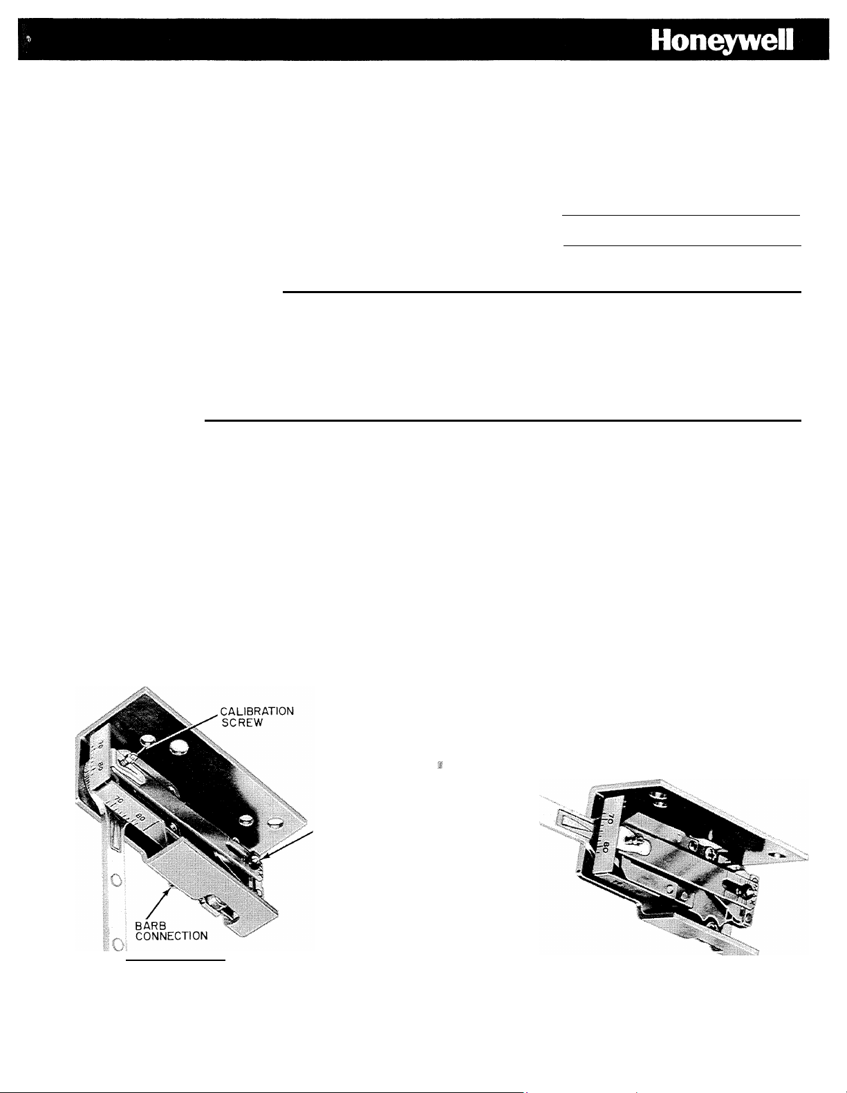
The TP975 Diffuser Thermostat is designed to provide
proportional control for pneumatic valves and mixing boxes in
heating or air conditioning systems. It is a one-pipe thermostat
which mounts in one end of a slot or light troffer diffuser; or
in a return air grille. Air connection is a sharp barb fitting for
5/32
plastic tubing. The TP975 is factory calibrated, however,
field calibration is possible. The proportional band (TR) is
adjustable from 2 to
The
TP975A
acting. Normal main line pressure is 18
is direct acting while the
1OF.
TP975B
psig
is reverse
.
PROPORTIONAL
BAND ADJ. (TR)
Mounting
The thermostat can be mounted in a variety of positions in fan
coil units, return air grilles (wall or ceiling) or in a plenum
return The
degrees to line up in two different mounting planes,
NOTE: On fan coil units it is not recommended to apply a
setpoint
return air thermostat to a unit with a 100 percent
outdoor air damper interference and the probability
of reducing air flow across the thermostat.
lever of the TP975 can be rotated 90
Fig. 1. TP975 with
SETPOINT
ADJ. LEVER
Setpoint
Lever in Vertical Position. Fig. 2, TP975 with
R974 R973
Setpoint
Copyright © 1973 Honeywell Inc. � All Rights Reserved MLF TAB: ll.C.2.a.
Lever
in
Horizontal Position.
95-7152
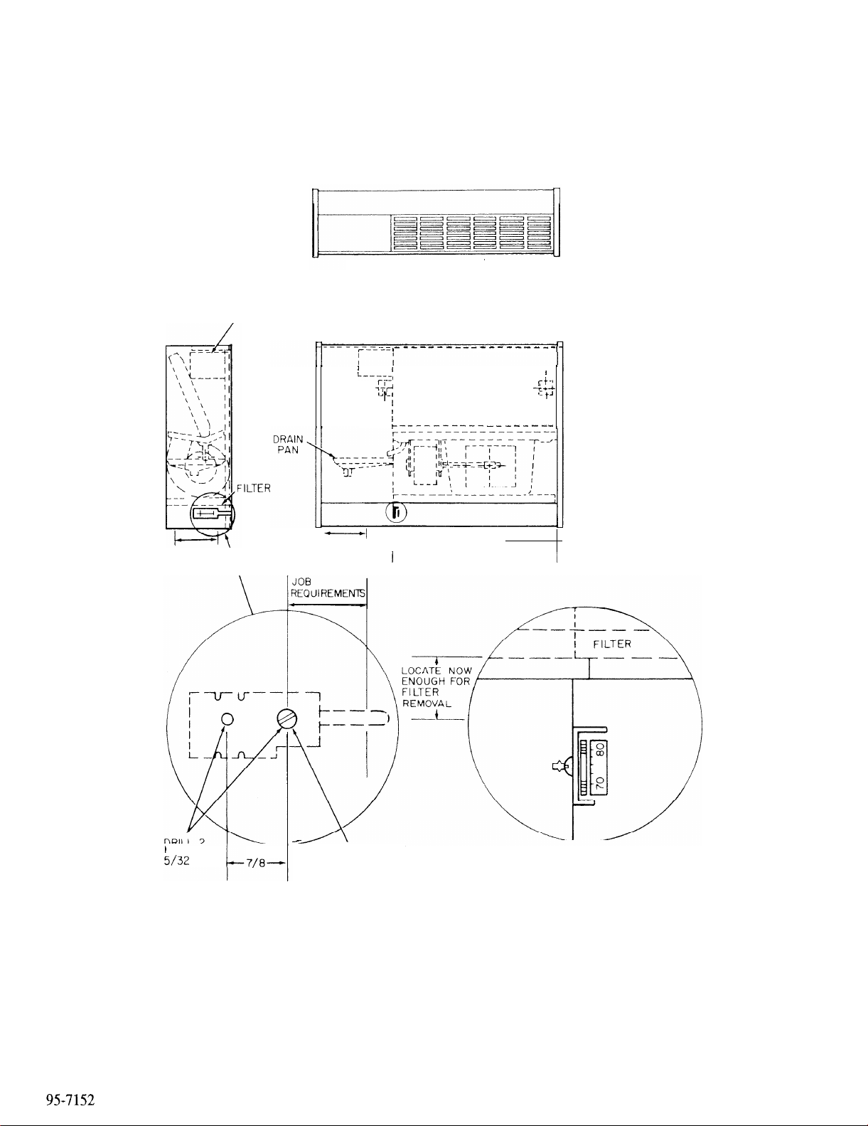
MOTOR CONTROL
AND JCT BOX
TOP GRILLE
PIPING
OPENING
HOLES
MIN
PIPING
OPENING
\
LOCATE PER
8-32 x3/8 (MAX)
-OPENING FRONT
4070
Fig. 3. Mounting in a Typical Fan Coil Unit.
2
 Loading...