

Page 1

TP970-72, TP970-74, TP9600, and TP9630
Pneumatic Sensors, Humidistats,
and Thermostats
INSTALLATION INSTRUCTIONS
Contents
INTRODUCTION ............................................................................................................................ 2
BEFORE INSTALLATION ............................................................................................................................ 2
INSTALLATION ............................................................................................................................ 9
CALIBRATION .......................................................................................................................... 45
Tools and Accessories ........................................................................................ 2
General ............................................................................................................... 2
Dimensions ......................................................................................................... 4
Covers ................................................................................................................ 5
General ............................................................................................................... 5
Removing and Replacing Covers ....................................................................... 6
Installing Cover Inserts ....................................................................................... 7
Painting (Beige Plastic Covers Only).................................................................. 7
Installation with Recessed Tubing ...................................................................... 9
Hollow-Core Studded Wall ................................................................................. 9
Block or Brick Wall ............................................................................................ 28
Concrete Pour .................................................................................................. 34
Mullion .............................................................................................................. 38
Installation with Surface-Mounted Tubing ........................................................ 40
Piping................................................................................................................ 45
Tools Required ................................................................................................. 45
Humidistat/Humidity Sensor ............................................................................. 45
General ............................................................................................................. 45
Setpoint Lock .................................................................................................... 46
Throttling Range Adjustment (HP970 and HP972) ........................................... 46
Calibration Check ............................................................................................. 46
Recalibration .................................................................................................... 46
Thermostat/Temperature Sensor ...................................................................... 47
General ............................................................................................................. 47
Throttling Range Adjustment ............................................................................ 47
Calibration Check ............................................................................................. 47
Recalibration .................................................................................................... 47
APPENDIX: BACKPLATES .......................................................................................................................... 48
® U.S. Registered Trademark
Copyright © 1998 Honeywell Inc. • All Rights Reserved
General ............................................................................................................. 48
Removing Stat from Conventional Backplate ................................................... 48
Removing Stat from Quick-Mount Backplate.................................................... 48
95-5597-1
Page 2
TP970-72, TP970-74, TP9600, AND PNEUMATIC SENSORS, HUMIDISTATS, AND THERMOSTATS
INTRODUCTION
The BEFORE INSTALLATION section shows tools and
accessories used during installation and calibration,
dimensions of major accessories, and procedures for
preparing thermostat and humidistat covers. The
INSTALLATION section shows how to install thermostats,
humidistats, sensors, and fittings and shows connections for
one- and two-pipe applications. The CALIBRATION section
describes calibration and adjustment procedures.
For information on how to remove a stat body from a stat
backplate, refer to APPENDIX: BACKPLATES.
BEFORE INSTALLATION
Tools and Accessories
General
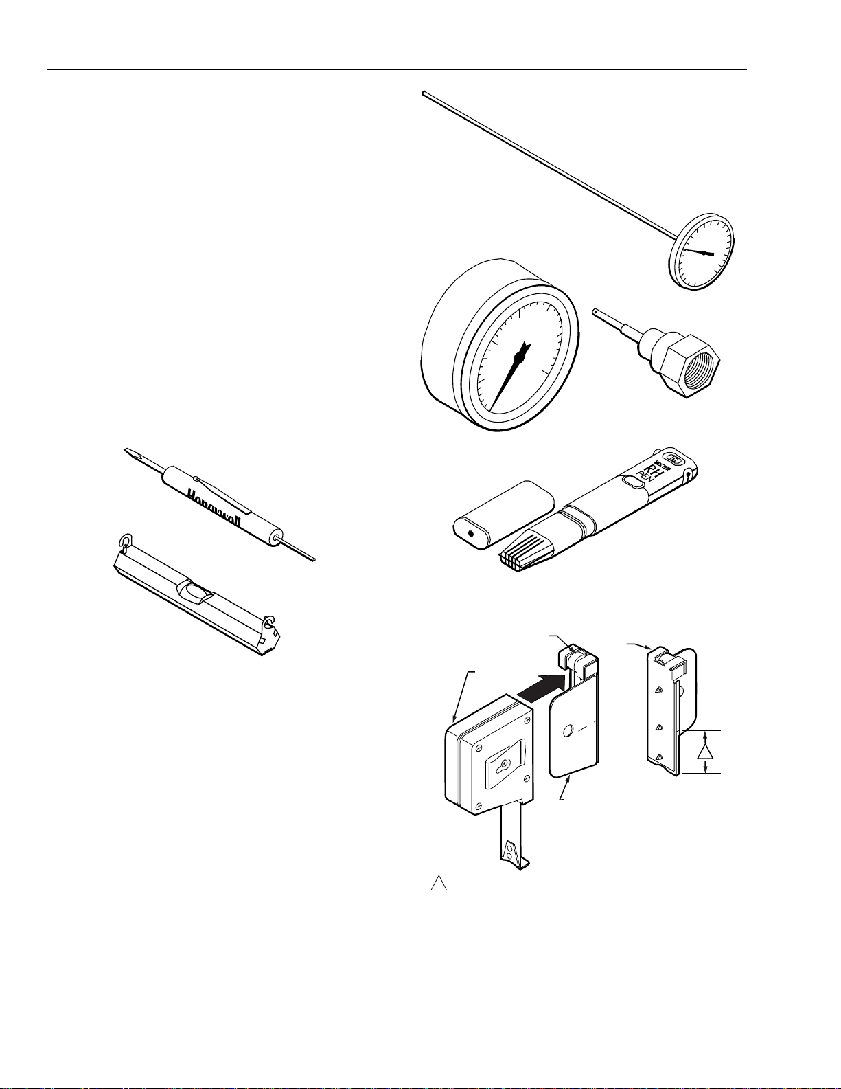
Figure 1 shows tools used for stat installation. Figure 2 shows
tools used during calibration check. Figures 3 through 8 show
accessories used for several mounting methods.
10
5
0
GAGE 305965
0-30 PSI (0-207 kPa)
TEST THERMOMETER
CCT902
20
15
25
30
GAGE PORT NEEDLE
(CCT729A CAN BE USED TO
CONNECT TO 5/32 IN. AND 1/4 IN.
POLYETHYLENE TUBING)
120
140
100
160
80
180
60
200
40
220
20
0
THERMOSTAT TOOL
POCKET LEVEL CCT348
C3150-1
Fig. 1. Installation Tools Used for All Mounting Methods.
DIGITAL RELATIVE
HUMIDITY INDICATOR
PEN CCT915
Fig. 2. Calibration Tools.
LEVEL
TAPE
MEASURE
1—1/2 IN. (38 MM) FROM BOTTOM OF TAPE MEASURE TO
1
CENTER MARK CORRESPONDING TO CENTER OF STAT.
BACK
VIEW
C
L
THERMOSTAT
MOUNTING
GUIDE TOOL
C3928
1
C3151
95-5597—1
Fig. 3. Tape Measure CCT422 and Thermostat
Mounting Guide Tool CCT690.
2
Page 3
TP970-72, TP970-74, TP9600, AND TP9630 PNEUMATIC SENSORS, HUMIDISTATS, AND THERMOSTATS
PROTECTIVE SLEEVE FOR BORE
REPLACEMENT PROTECTIVE SLEEVES
ARE AVAILABLE. ORDER CCT691A.
THERMOSTAT STEP/BORING TOOL
CORDLESS DRILL
WARNING
! !
TO AVOID BODILY INJURY AND PROTECT
BORE, LEAVE PROTECTIVE SLEEVE ON
STEP/BORING TOOL EXCEPT WHEN
DRILLING WITH BORE.
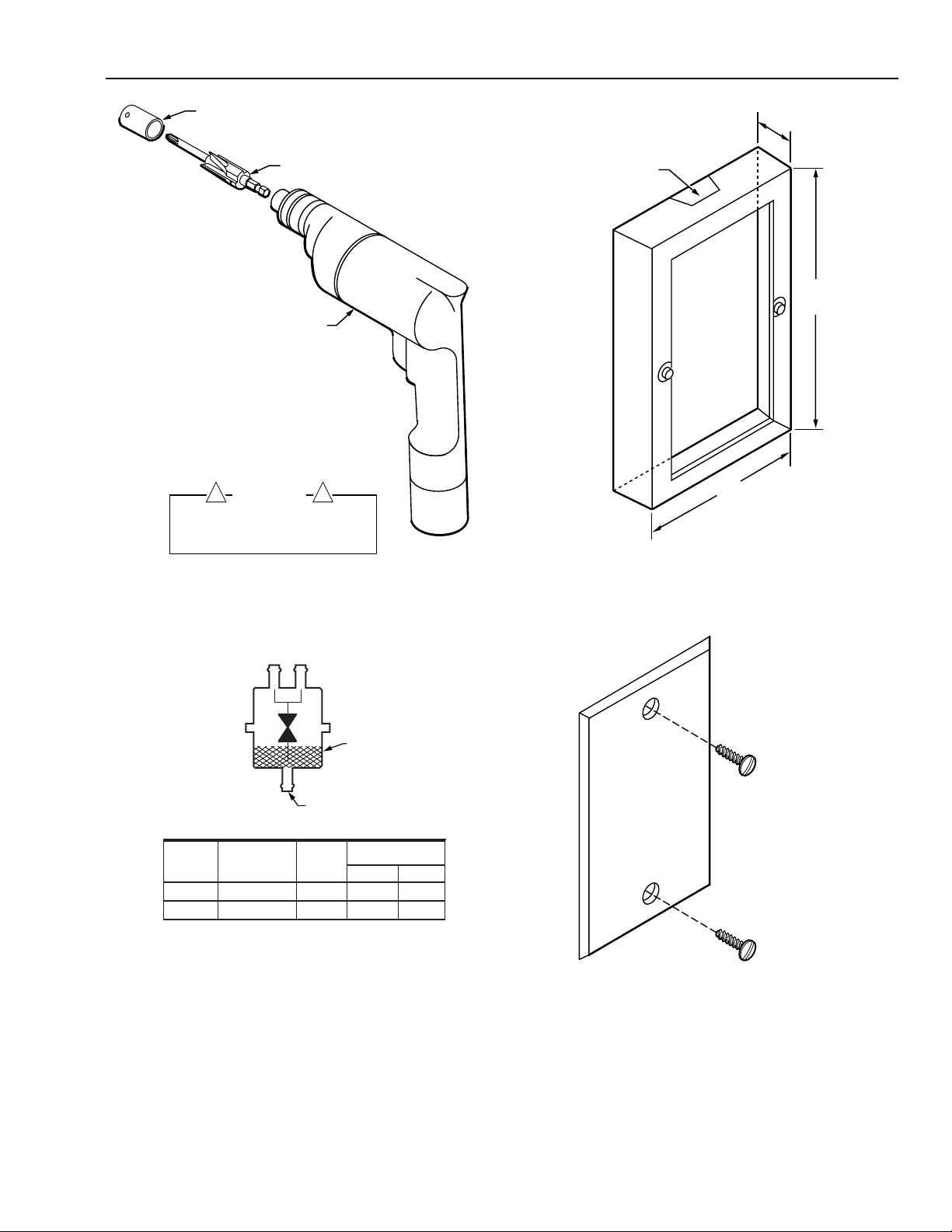
Fig. 4. Thermostat Step/Boring Tool CCT691
and Cordless Drill CCT713.
C3152
1/2
(13)
REMOVABLE WEB
(CUT AWAY WITH
POCKET KNIFE)
3-17/32
(90)
2-5/16
(59)
C3153
Fig. 6. Wall Mounting Ring 14004458-001 for Flush or
Surface Mounting to Brick or Block Wall or to Wall
with Surface-Mounted Tubing.
SEE CHART FOR BARB SIZE
REMOTE RESTRICTORS
PART NO. ORIFICE BODY
14002913– SIZE IN INCHES COLOR
–001* 0.005 Blue 1/4 (6)
–004 0.005 Blue 5/32 (4)
* ONE BARB CAP 14003567-001 FURNISHED WITH RESTRICTOR
BA
FILTER
INLET
ALL INLET BARBS
1/4 IN. (6 MM)
BARB SIZE
IN INCHES (MM)
A B
5/32 (4)
5/32 (4)
C3931-1
Fig. 5. Remote Restrictors Used for Piping.
NOTE: USE FOR APPLICATION WITH RECESSED TUBING WHEN
STAT IS TO BE MOUNTED AT A LATER DATE
C3154
Fig. 7. Wall Plate Bag Assembly 14001905-001.
3
95-5597—1
Page 4
TP970-72, TP970-74, TP9600, AND PNEUMATIC SENSORS, HUMIDISTATS, AND THERMOSTATS
Dimensions
Figures 9 through 13 show dimensions of major installation
accessories.
4-1/2
(115)
4-5/8
(117)
2-3/4 (70)
C5532
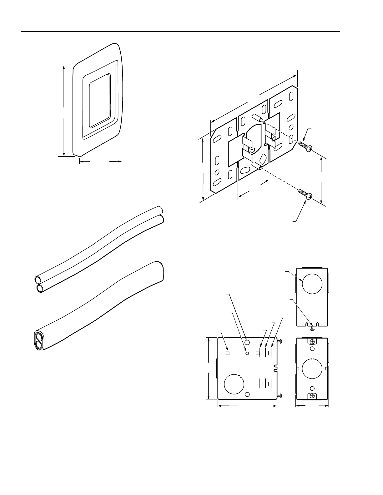
Fig. 7A. Wall Plate Bag Assembly 14002136-004.
TWIN TUBE
AK3240 (5/32 IN. O.D. X 0.030 IN. WALL) OR
AK3241 (1/4 IN. O.D. X 0.040 IN. WALL)
BUNDLED TUBING AK3168
(5/32 IN. O.D. X 0.030 IN. WALL)
2-7/8
(73)
1-11/16
(43)
NO. 6-32 X 1/2 IN.
MOUNTING SCREW (2)
PROVIDED WITH
SHALLOW WALLPLATE
Fig. 9. Shallow Wall Plate 14001614-001
Dimensions in Inches (Millimeters).
KNOCKOUT FOR 1/2 IN. CONDUIT OR
FITTING SNAP RING (BOTH SIDES,
BACK, TOP AND BOTTOM)
3/16 (5)
(6 PLACES)
TAPPED HOLE
8 x 32 (2 PLACES)
GUIDES FOR
MOUNTING
BRACKET
TAPPED HOLE (2) 6 x 32
MOUNTING SCREWS
6 x 32 - 1/2 (PROVIDED)
ALIGNMENT
FOR FINISHED WALL
3/4 (19)
1/2 (13)
1/4 (6)
2-1/4
(57)
C3180
C3155
Fig. 8. Twin Tube AK3240 (5/32 in. O.D. x 0.030 in. wall)
or AK3241 (1/4 in. O.D. x 0.040 in. wall) and Bundled
Tubing AK3168 (5/32 in. O.D. x 0.030 in. wall).
95-5597—1
2-5/8
(67)
2-9/16 (65)
1-7/16
(37)
C3930
Fig. 10. Deep Wall Box 14001355-001
Dimensions in Inches (Millimeters).
4
Page 5
TP970-72, TP970-74, TP9600, AND TP9630 PNEUMATIC SENSORS, HUMIDISTATS, AND THERMOSTATS
1 IN. (25 MM)
OFFSET FOR BOX
2 IN. (51 MM)
OFFSET FOR BOX
1-1/2
(38)
3-1/16 (78)
1-7/16 (37)
C3179
STUD-MOUNTED
STAT PLATE
(ALIGN OVER
ELECTRICAL BOX)
NO. 6-32 X 1/2 IN.
MOUNTING SCREW (2)
PROVIDED WITH
STUD-MOUNTED
STAT PLATE
EXTENSION
PLATE
3-15/16
(100)
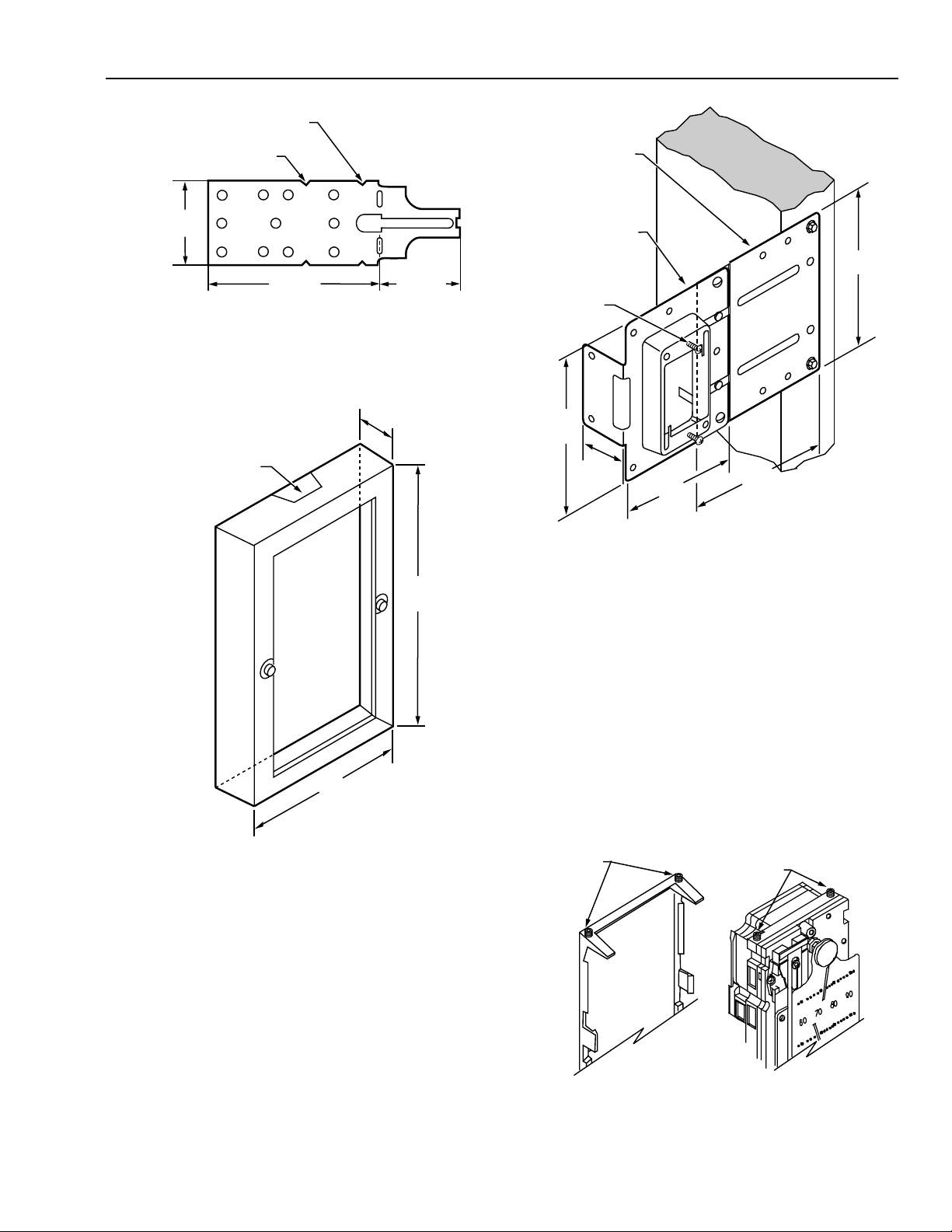
Fig. 11. Deep Wall Box Mounting Bracket 14001354-001
Dimensions in Inches (Millimeters).
1/2
(13)
REMOVABLE WEB
(CUT AWAY WITH
POCKET KNIFE)
3-17/32
(90)
2-5/16
(59)
C3153
3-15/16
(100)
1-1/16
(27)
3-1/16
(78)
3-9/16
(91)
C3933
Fig. 13. Stud-Mounted Stat Plate 14004610-001
and Extension Plate 14004656-001
Dimensions in Inches (Millimeters).
Covers
General
This section shows how to remove and replace thermostat
and humidistat covers and how to install Inserts over the
setpoint and DAY/AUTO slots at the bottom of covers. This
section also lists recommended paints for covers that can be
painted and describes painting procedures.
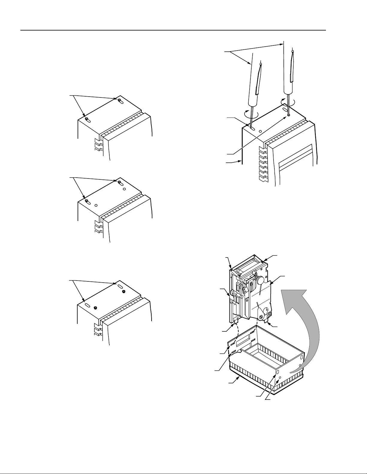
Cover assembly and disassembly differs between
conventional and Quick-Mount stats. On a conventional stat
the cover mounts to setscrews in the backplate, while on a
Quick-Mount stat the cover mounts to setscrews in the stat
body (Fig. 14).
Fig. 12. Wall Mounting Ring 14004458-001
Dimensions in Inches (Millimeters).
CONVENTIONAL STAT
SETSCREWS
5
QUICK-MOUNT STAT
SETSCREWS
STAT BACKPLATE
STAT BODY
C3569
Fig. 14. Setscrew Locations for Conventional
and Quick-Mount Stats.
95-5597—1
Page 6
TP970-72, TP970-74, TP9600, AND PNEUMATIC SENSORS, HUMIDISTATS, AND THERMOSTATS
R
To determine the cover mounting method, look at the holes at
the top of the cover (Fig. 15). If the setscrews are raised
against the back pair of slots (toward the wall), the setscrews
are in the backplate and the stat is a conventional stat. If the
setscrews are raised into the front pair of holes, the setscrews
are in the stat body and the stat is a Quick-Mount stat.
CONVENTIONAL STAT
SETSCREWS VISIBLE
THERMOSTAT TOOL
CONVENTIONAL STAT
SETSCREW SLOT (2)
SETSCREWS VISIBLE
SETSCREWS VISIBLE
QUICK-MOUNT STAT
SPECIAL COVER
STANDARD COVE
QUICK-MOUNT STAT
SETSCREW HOLE (2)
COVER
60
70
80
Honeywell
Fig. 16. Removing Cover.
Use the following procedure to replace a cover:
1. Hook slots at bottom of cover over two bottom tabs of
stat (Fig. 17). Setpoint adjustment will align with
setpoint slot.
CONVENTIONAL STAT
SETSCREW LOCATION (2)
STAT
BACKPLATE
70
60
QUICK-MOUNT STAT
SETSCREW LOCATION (2)
STAT
90
80
90
C3158
STANDARD COVER
C3157
Fig. 15. Conventional and Quick-Mount Stats.
Removing and Replacing Covers
Cover assembly/disassembly requires Thermostat Tool
CCT735A (MQT735A). Use the following procedure to
remove a cover:
1. Locate setscrews in cover (back pair of slots for conventional stat, front pair of holes for Quick-Mount stat).
2. Place Allen wrench end of Thermostat Tool through slot/
hole and into setscrew (Fig. 16).
3. Rotate Thermostat Tool clockwise until setscrew no
longer touches cover. Repeat for other setscrew.
4. Pull Cover out and down.
95-5597—1
CONVENTIONAL STAT
MOUNTING SLOT (2)
QUICK-MOUNT STAT
MOUNTING SLOT (2)
6
CONVENTIONAL
STAT TAB (2)
COVER
CONVENTIONAL STAT
SETSCREW SLOT (2)
Fig. 17. Replacing Cover.
QUICK-MOUNT
STAT TAB (2)
QUICK-MOUNT STAT
SETSCREW HOLE (2)
C4110
Page 7
TP970-72, TP970-74, TP9600, AND TP9630 PNEUMATIC SENSORS, HUMIDISTATS, AND THERMOSTATS
COVER
SETPOINT
SLOT
SETPOINT
COVER
M10827
INSERT
2. Swing cover up and over stat.
3. Place Allen wrench end of Thermostat Tool through
setscrew slot and into setscrew.
4. Rotate Thermostat Tool counterclockwise until setscrew
holds cover securely onto stat backplate (conventional
stat) or stat body (Quick-Mount stat). Repeat for other
setscrew.
Installing Cover Inserts
The following Cover Inserts are available for the setpoint and
DAY/AUTO lever slots on stat covers:
Part No. Finish
14004437 -001 Satin
Chrome
-002 Beige
Plastic
14004438 -001 Satin
Chrome
-002 Beige
Plastic
14004442 -001 Black 14002132-XXX
Covers Slot
14004406-XXX
Standard Covers*
14004407-XXX
Standard Covers*
14004406-XXX
Standard Covers*
14004407-XXX
Standard Covers*
Special Covers†
DAY/AUTO
Setpoint
DAY/AUTO
Setpoint
* See HP970 and TP970 Series Standard Covers and
Accessories Specification Data 77-1003.
† See HP970 and TP970 Series Standard Covers
Specification Data 77-9828.
Cover Inserts are removable. Covers ship with setpoint and
DAY/AUTO lever slots “open” (without Insert) or “closed” (with
Insert present) as follows:
— Setpoint slot: Open or closed as ordered (see HP970
and TP970 Series Standard Covers and Accessories
Specification Data 77-1003 and HP970 and TP970
Series Special Covers and Accessories Specification
Data 77-9828)
— DAY/AUTO lever slot:
• No Insert on vertical stat covers
• Insert present on horizontal stat covers
Applicable
Fig. 19. Installing Setpoint Cover Insert
14004438-001/-002.
Painting (Beige Plastic Covers Only)
Beige Plastic Covers can be painted with recommended
paints before or after Covers are installed.
Recommended Paints
If a non-latex paint is required, use Rust-Oleum Enamel (a
fish-oil type enamel). No primer is needed.
If a latex paint is required, use one of the following as a
primer and follow with any latex wall paint:
— Sears Anti-Rust Enamel (a soya-alkyd type enamel in a
spray can)
— True Value Tru-Test X-O Stain Primer/Sealer Stain Killer
XOS-1 White (a white-pigmented, shellac type primer)
Painting Procedures
Painting Cover before Window is Installed
Order the following equipment:
— Cover Assembly 14004402-002
— DAY/AUTO Cover Insert 14004437-002 (optional)
— Setpoint Cover Insert 14004438-002 (optional)
— Window 14004405-XXX according to the following table:
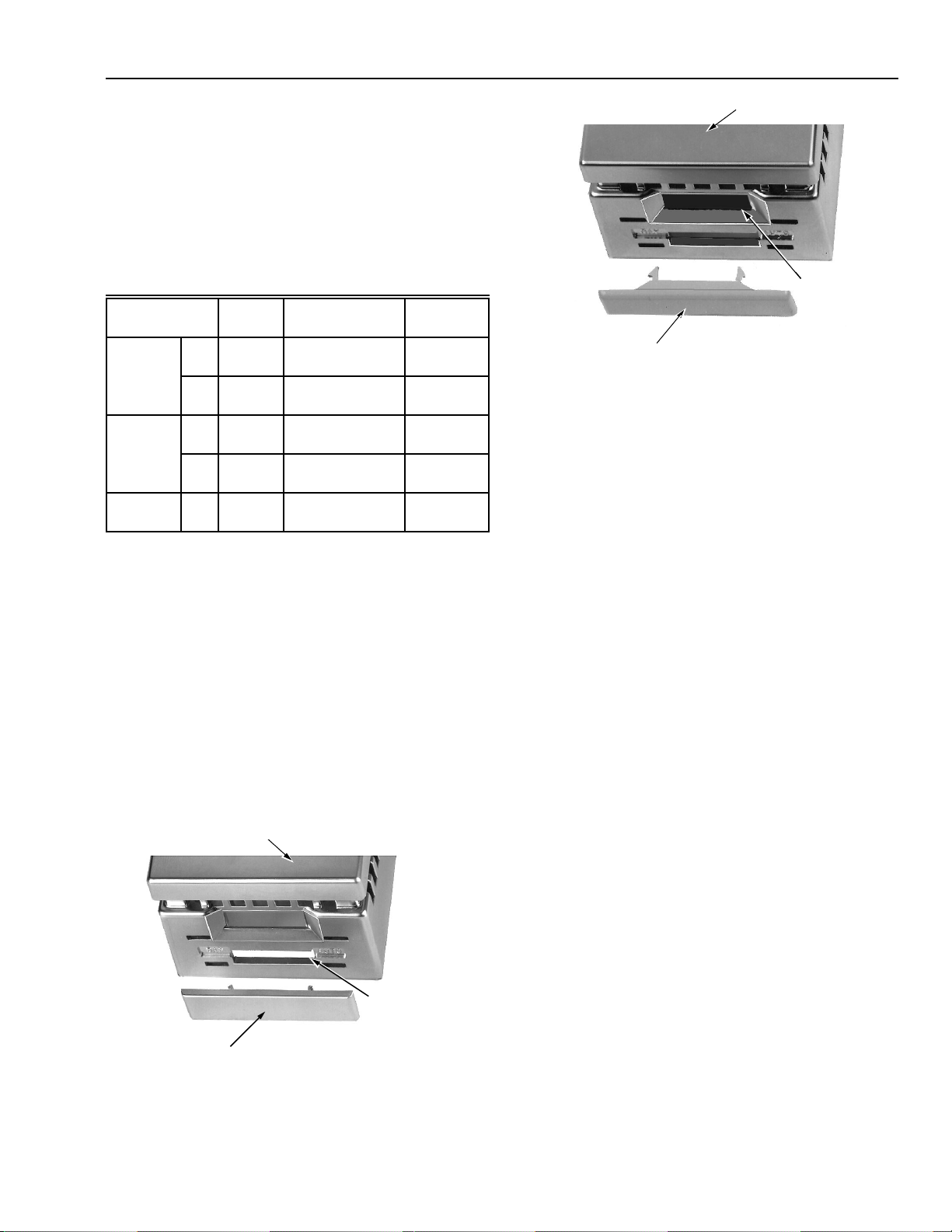
Figures 18 and 19 show how to install Inserts.
COVER
SLOT
COVER
INSERT
UNUSED
SLOT
Fig. 18. Installing DAY/AUTO Cover Insert
14004437-001/-002.
M10828
1. Remove or add Inserts to Cover Assembly as required
(see INSTALLING COVER INSERTS).
2. Wash Cover Assembly with mild dish detergent solution.
3. Dry with paper towel.
4. Paint with approved paint.
5. Allow to dry.
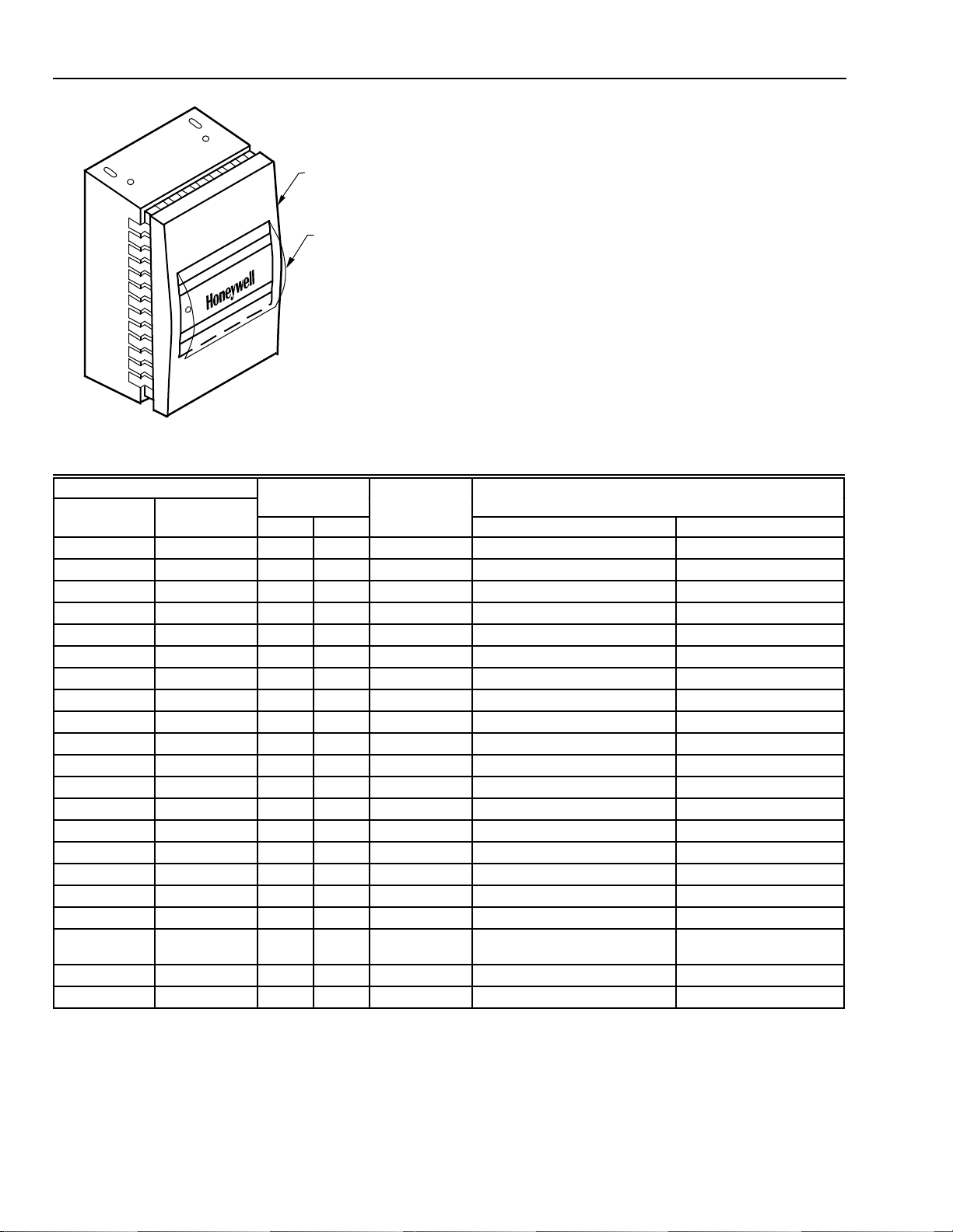
6. When Window has been assembled to Cover,
disassembly may damage Window. Before installing
Window, note the following:
a. Check that Window display is correct for job
requirements.
b. Check Window orientation to cover. Cover
setpoint and DAY/AUTO lever slots should be on
the bottom (vertical mounting) or to the right
(horizontal mounting).
7. Remove liner from adhesive on back of Window. Slide
Window into Cover opening (Fig. 20) and press in place.
7
95-5597—1
Page 8
TP970-72, TP970-74, TP9600, AND PNEUMATIC SENSORS, HUMIDISTATS, AND THERMOSTATS
Painting Cover after Window is Installed
Order the following equipment:
— Cover Assembly 14004407-XXX (select from HP970 and
COVER
0
9
0
8
0
7
0
6
0
9
0
8
0
7
0
6
WINDOW CURVED
FOR INSTALLATION
Fig. 20. Installing Window.
C3156
TP970 Series Standard Covers and Accessories Spec
Data 77-1003)
— Paint Mask 14002193-001
— DAY/AUTO Cover Insert 14004437-002 (optional)
— Setpoint Cover Insert 14004438-002 (optional)
1. Remove or add Inserts to Cover Assembly as required
(see INSTALLING COVER INSERTS).
2. Wash Cover Assembly with mild dish detergent
solution. Do not immerse.
3. Dry with paper towel.
4. Apply Paint Mask to window. Trim around window as
needed.
5. Paint with approved paint.
6. Allow to dry.
7. Remove Paint Mask.
Window 14004405-XXX
Stat
Orientation Honeywell Display (Unit)Silver Beige
Background Background
Vert. Horiz.
Logo
Setpoint Thermometer
-001 -101 X X None None
-002 -102 X X None None
-003 -112 X X None None
-004 -113 X 60-90 (F) 60-90 (F)
-005 -103 X X 60-90 (F) 60-90 (F)
-006 N/A X X 40-70 (F) 40-70 (F)
-007 -104 X X 15-30 (C) 15-30 (C)
-008 -106 X X 60-90 (F) None
-009 N/A X X 40-70 (F) None
-010 N/A X X 15-30 (C) None
-011 N/A X X None 60-90 (F)
-012 N/A X X None 15-30 (C)
-013 N/A X 60-90 (F) 60-90 (F)
-014 N/A X X 60-90 (F) 60-90 (F)
-015 -105 X X 15-30 (C) 15-30 (C)
-016 -107 X X 20-80 (% rh) None
-017 N/A X X 20-80 (% rh) None
-018 N/A X X COOLER/WARMER None
-019 N/A X X HEAT RANGE/COOL RANGE
60-90 (F)
N/A -110 X X 15-30 (C) 60-90 (F)
-021 N/A X X 40-70 (F) 40-70 (F)
60-90 (F)
95-5597—1
8
Page 9
TP970-72, TP970-74, TP9600, AND TP9630 PNEUMATIC SENSORS, HUMIDISTATS, AND THERMOSTATS
C3181
INSTALLATION
This section categorizes stat installation according to the
following factors:
— Location of tubing: recessed or surface-mounted
— Type of wall: hollow-core studded, block or brick,
concrete, or mullion
— Condition of wall: rough-in or finished
Installation with Recessed Tubing
Examples of installations with recessed tubing include:
hollow-core stud walls, block or brick walls, concrete walls,
and mullions.
Hollow-Core Studded Wall
A hollow-core studded wall requires either rough-in mounting
or finished-wall installation.
Rough-In Installation
Rough-in installation is done to a stud before the wall is
drywalled or to lath before the wall is plastered.
NOTE: If the wall is already drywalled or plastered, see
FINISHED WALL INSTALLATION.
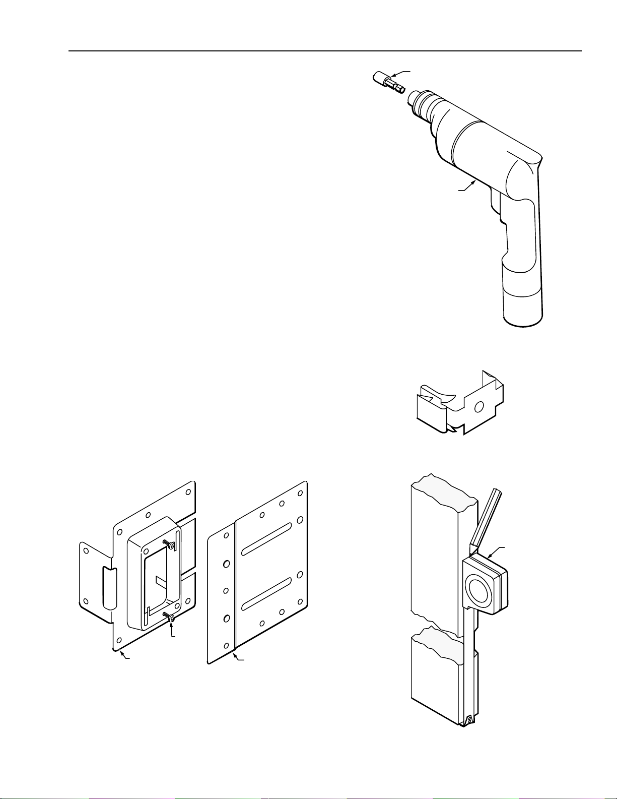
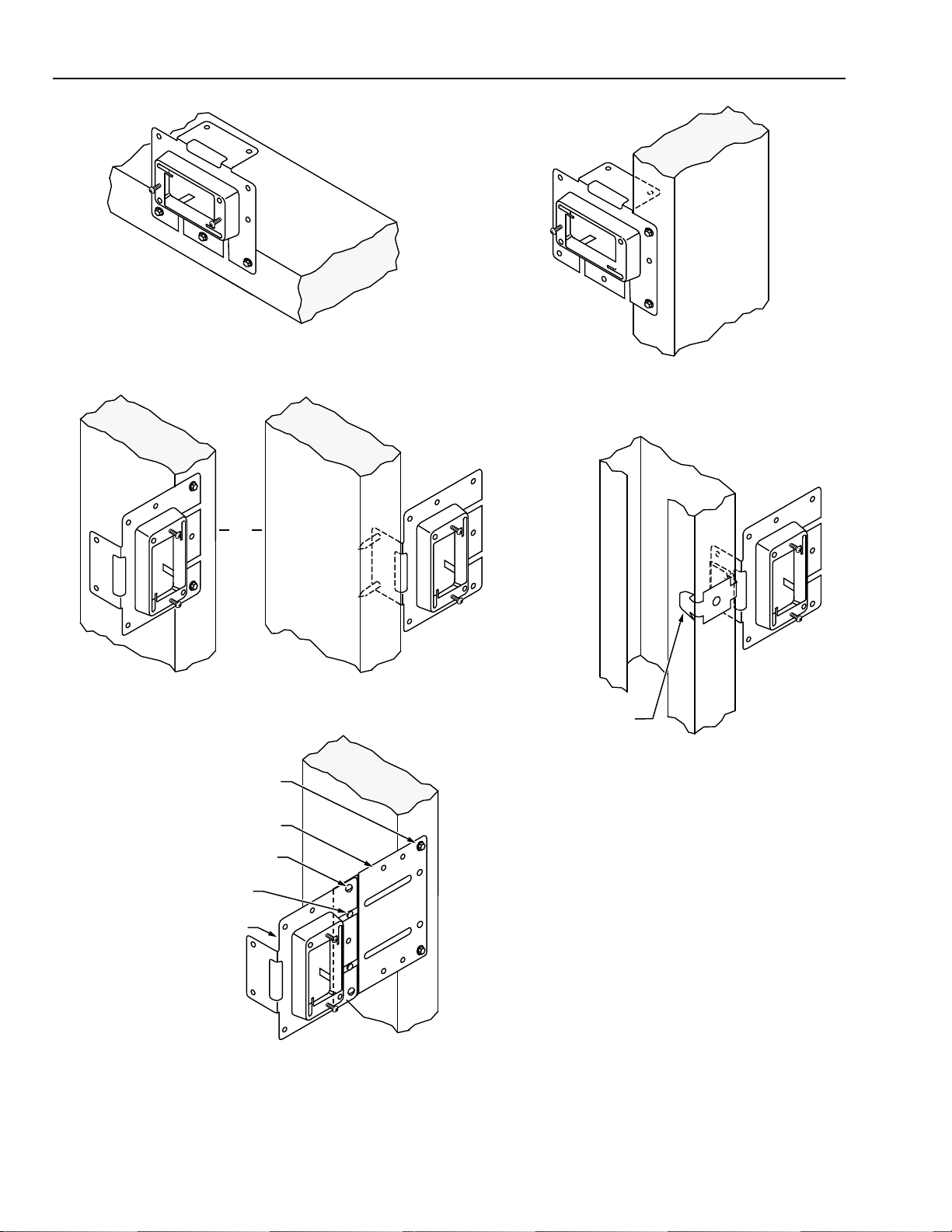
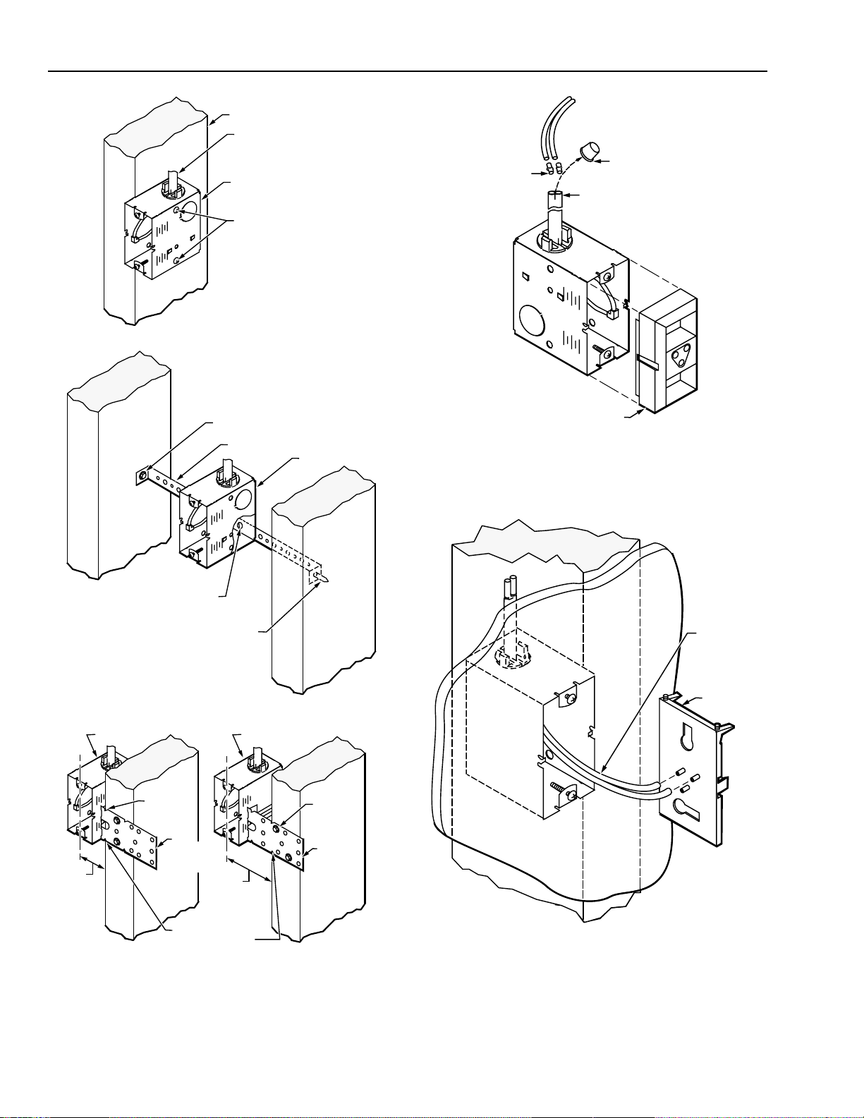
Mounting to Stud with Stud-Mounted Stat Plate
Mounting to a stud using a Stud-Mounted Stat Plate requires
the following equipment:
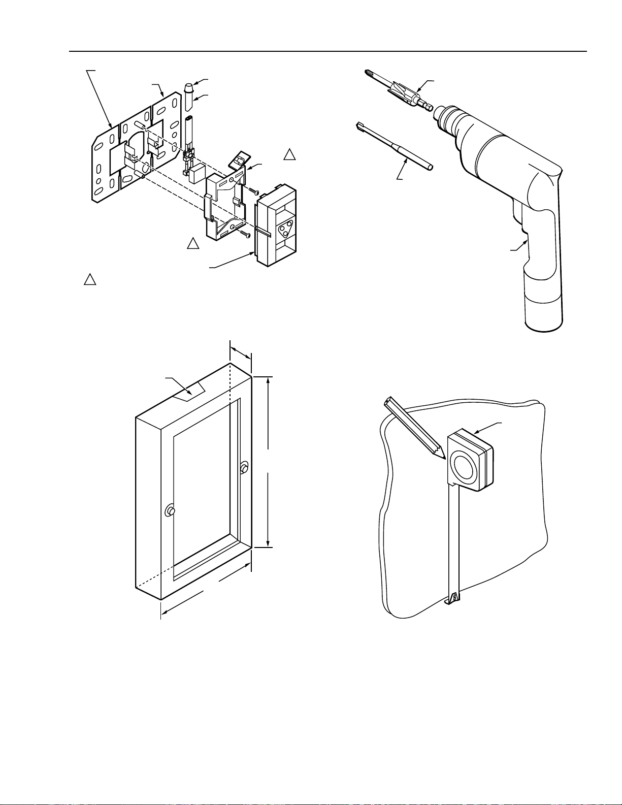
— Stud-Mounted Stat Plate 14004610-001 (Fig. 21)
— Extension Plate 14004656-001 (optional) (Fig. 21)
— Tape Measure CCT422
— No. 8 sheet metal screws
— Cordless Drill CCT713 (Fig. 22)
— TEK Drill Adapter Screwdriver CCT240 (Fig. 22)
— No. 8 x 1/2 in. TEK Screws CCT2444 (two per stat)
— Stud Mount Box Clip CCT2642 for mounting Stud-
Mounted Stat Plate to metal stud (Fig. 23) (optional)
— Thermostat Tool CCT735A (MQT735A)
TEK DRILL ADAPTER
SCREWDRIVER
CORDLESS DRILL
C3167
Fig. 22. TEK Drill Adapter Screwdriver and Cordless Drill.
Fig. 23. Stud Mount Box Clip.
SCREWS
PROVIDED
STUD-MOUNTED
STAT PLATE
NOTE: MAXIMUM EXTENSION IS 2-3/4 IN. (70 MM) USING
ONE PLATE, 5-3/8 IN. (137MM) USING TWO PLATES.
Fig. 21. Stud-Mounted Stat Plate and
Optional Extension Plate.
EXTENSION PLATE
C3932
TAPE
MEASURE
C3162
1. Measure and mark approximate stat location on stud.
9
95-5597—1
Page 10
TP970-72, TP970-74, TP9600, AND PNEUMATIC SENSORS, HUMIDISTATS, AND THERMOSTATS
HORIZONTAL MOUNTING TO HORIZONTAL STUD
HORIZONTAL MOUNTING TO VERTICAL STUD
OR VERTICAL MOUNTING TO HORIZONTAL STUD
OR
VERTICAL MOUNTING TO VERTICAL STUD
TEK SCREW (2)
EXTENSION PLATE
SHEET METAL SCREW (2)
EXTENSION PLATE
BUTTON (2)
STUD-MOUNTED
STAT PLATE
STUD MOUNT
BOX CLIP
MOUNTING TO METAL STUD
(REQUIRES STUD MOUNT BOX CLIP CCT2642)
NOTE:
TO ATTACH STUD-MOUNTED STAT PLATE TO EXTENSION PLATE:
A. FIT TWO BUTTONS ON EXTENSION PLATE INTO SLOTS
ON STUD-MOUNTED STAT PLATE.
ALIGN TWO OUTER HOLES AND/OR SINGLE CENTER
B.
HOLES ON TWO PLATES.
FASTEN PLATES TOGETHER WITH NO. 8 x 1/2 IN.
C.
SHEET METAL SCREWS.
FASTEN EXTENSION PLATE TO STUD USING
D.
NO. 8 x 1/2 IN. TEK SCREWS.
TYPICAL MOUNTING WITH EXTENSION PLATE
C3937
2. Attach Stud-Mounted Stat Plate, using Extension Plate if required to center stat over electrical box. Use Cordless Drill and
TEK Screwdriver Drill Adapter to drive No. 8 x 1/2 in. TEK screws, or use Stud Mount Box Clip as required.
95-5597—1
10
Page 11
TP970-72, TP970-74, TP9600, AND TP9630 PNEUMATIC SENSORS, HUMIDISTATS, AND THERMOSTATS
STAT
BACKPLATE
STAT
C3573
TUBING
STUD-MOUNTED
STAT PLATE
STUD MOUNTED
STAT PLATE
TAB
STAT
BACKPLATE
C3934
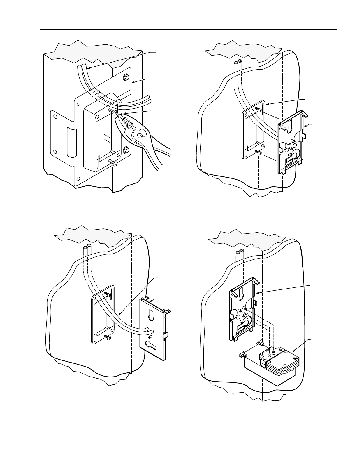
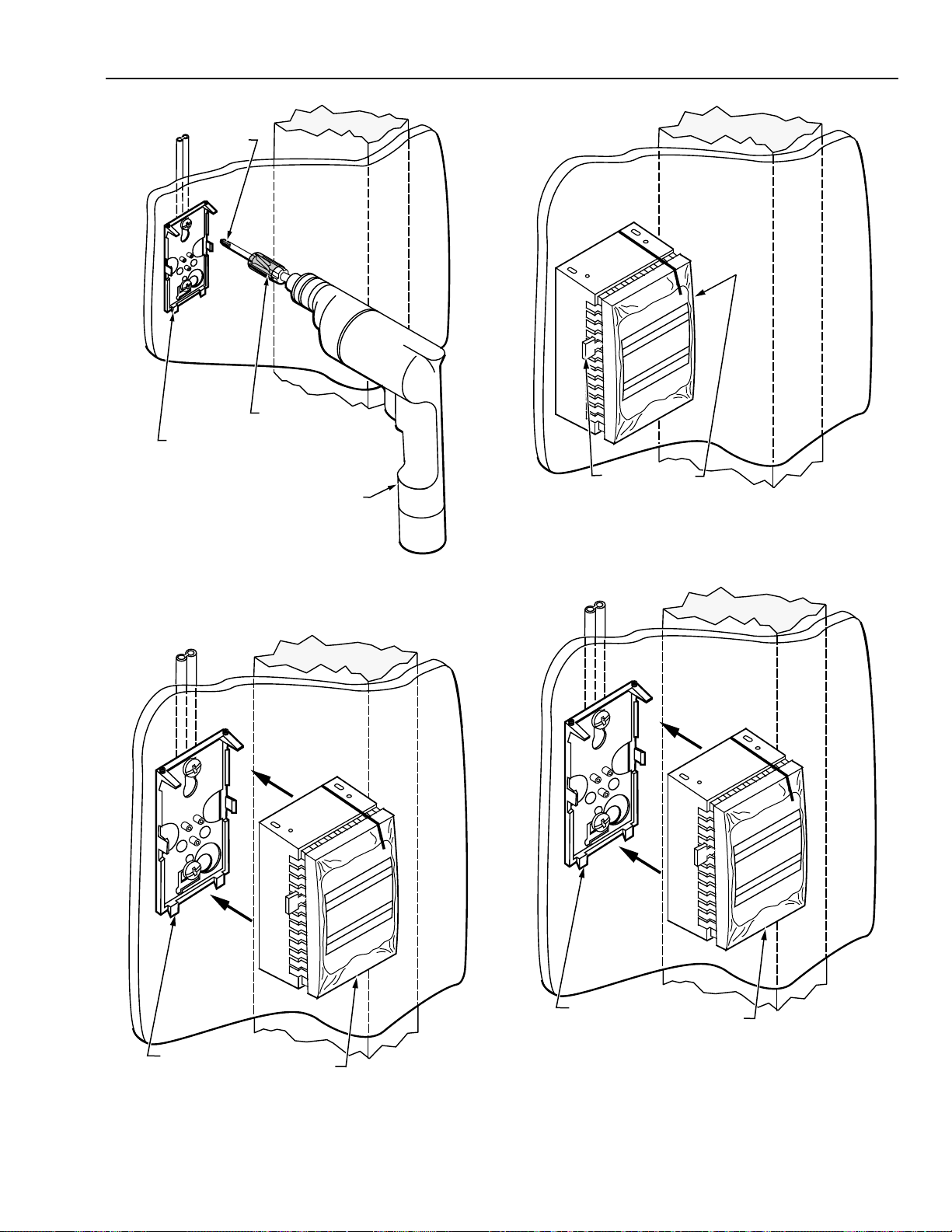
3. Fish tubing through Stud-Mounted Stat Plate. Anchor
tubing in upper-right or lower-left corner of Plate by
crimping Plate tab with pliers.
TUBING
STAT
BACKPLATE
C3936
5. Hook keyhole slots of stat backplate over backed-out
screws on Stud-Mounted Stat Plate. Level stat
backplate and tighten screws.
C3935
4. After drywall or plaster is up, release tubing from corner
of Plate. Connect tubing to barbs on stat backplate.
6. Mount stat to stat backplate.
11
95-5597—1
Page 12
TP970-72, TP970-74, TP9600, AND PNEUMATIC SENSORS, HUMIDISTATS, AND THERMOSTATS
Mounting to Stud with Deep Wall Box
Mounting to a stud using a Deep Wall Box requires the
following equipment:
SETSCREWS
STAT
BACKPLATE
STAT
TAB (2)
COVER
SETSCREW
SLOTS
C4116
7. Hook slots on stat cover over bottom tabs on stat
backplate. Swing stat cover up and over stat. Use
Thermostat Tool to raise stat backplate setscrews into
setscrew slots on top of cover.
— Deep Wall Box Assembly 14001492-001 (includes two-
pipe plastic cable assembly, see Fig. 24) or separate
parts for one- and three-pipe applications as follows:
• Deep Wall Box 14001355-001
• Fitting Finder 14000706-001 (optional)
• One of the following:
14001491-001 one-pipe or -003 three-pipe Plastic
Cable Assembly
or
14001494-001 one-pipe, -002 two-pipe, or -003
three-pipe Copper Cable Assembly
— Barb Couplings CCT1606B (MJP1606B) (5/32 x 1/4 in.)
or CCT1628B (MJP1628B) (5/32 x 5/32 in.) for plastic
tubing (one, two, or three Couplings required according
to application)
— Tape Measure CCT422
— Cordless Drill CCT713 (Fig. 25)
— TEK Drill Adapter Screwdriver CCT240 (Fig. 25)
— The following items according to mounting method:
• Directly to stud:
Two No. 8 x 2 in. Pan Head Sheet Metal Screws
CCT2310 (MVH2310)
or
Two 6d 2 in. (51 mm) nails
• Between two studs:
Universal Strap CCT2630 (MVP2630) (Fig. 26)
Two No. 8 x 1/2 in. TEK Screws CCT2444
One No. 8-32 x 1/2 in. Round Head Screw CCT2410
• Offset from stud (e.g., to center over electrical box):
Deep Wall Box Mounting Bracket 14001354-001
One No. 8-32 x 1/4 in. Round Head Screw CCT2408
Two No. 8 x 1/2 in. TEK Screws CCT2444
— Thermostat Tool CCT735A (MQT735A)
DEEP WALL
BOX
ALIGNMENT GUIDE
FOR FINISHED WALL
NO. 6–32 X 1/2 IN. SCREW (2)
PROVIDED WITH DEEP WALL BOX
BUSHING
PROTECTOR CAP
PLASTIC CABLE
ASSEMBLY 8 FT (2.5 M)
BUSHING
FITTING
FINDER
CABLE ASSEMBLY
Fig. 24. Deep Wall Box Assembly and Cable Assemblies.
MAIN
BARB CAP
BRANCH
ONE-PIPE ASSEMBLY
SWITCH
MAIN
BRANCH
BARB TEE
THREE - PIPE ASSEMBLY
PROTECTOR CAP
BARB
COUPLINGS
FOR PLASTIC
TUBING
C3562
95-5597—1
12
Page 13
TP970-72, TP970-74, TP9600, AND TP9630 PNEUMATIC SENSORS, HUMIDISTATS, AND THERMOSTATS
TEK DRILL ADAPTER
SCREWDRIVER
CORDLESS DRILL
C3167
Fig. 25. TEK Drill Adapter Screwdriver and Cordless Drill.
1 (25)
NO. 8–32
3/4 (19)
MOUNTING
BRACKET
DEEP WALL BOX
NO. 8–32 X 1/4 IN.
SCREW
MOUNTING
BRACKET
NO. 6–32 X 1/2 IN.
SCREW (2) PROVIDED
DEEP WALL BOX
NO. 8–32 X 1/4 IN.
SCREW
C3566
24 (610)
Fig. 26. Universal Strap.
TAPE
MEASURE
C3161
2. If offset from stud is required (e.g., to center stat over
electrical box), attach Deep Wall Box to Deep Wall Box
Mounting Bracket with No. 8-32 x 1/4 in. Round Head
Screw.
C3162
1. Measure and mark approximate stat location on stud.
13
95-5597—1
Page 14
TP970-72, TP970-74, TP9600, AND PNEUMATIC SENSORS, HUMIDISTATS, AND THERMOSTATS
STUD
CABLE
ASSEMBLY
PROTECTOR CAP
PLASTIC CABLE
ASSEMBLY 8 FT (2.5 M)
DEEP WALL BOX
NO. 8 x 2 IN.
SHEET METAL SCREWS
OR 6d 2 IN. (51 MM) NAILS
MOUNTING DEEP WALL BOX DIRECTLY TO STUD
BARB
COUPLINGS
NO. 8 x 1/2 IN. TEK SCREW
UNIVERSAL STRAP
8-32 x 1/2 IN. ROUND HEAD SCREW
(INSTALL FROM INSIDE BOX)
NO. 8 x 1/2 IN.
TEK SCREW
MOUNTING DEEP WALL BOX BETWEEN STUDS
USING UNIVERSAL STRAP
DEEP WALL BOX DEEP WALL BOX
NO. 8 TEK
SCREWS (2)
DEEP WALL BOX
NO. 8 TEK
SCREWS (2)
FITTING FINDER
(IF WALL IS TO BE PLASTERED)
C3561
4. Remove protector cap from Cable Assembly. Attach
tubing to Cable with 5/32 x 1/4 in. or 5/32 x 5/32 in.
Barb Couplings. If wall is to be plastered, snap Fitting
Finder onto Deep Wall Box.
TUBING
STAT
BACKPLATE
1 (25)
OFFSET
DEEP
WALL BOX
MOUNTING
BRACKET
2 (51)
OFFSET
ALIGN BRACKET NOTCH
WITH EDGE OF STUD
DEEP
WALL BOX
MOUNTING
BRACKET
C3939
USING DEEP WALL BOX MOUNTING BRACKET
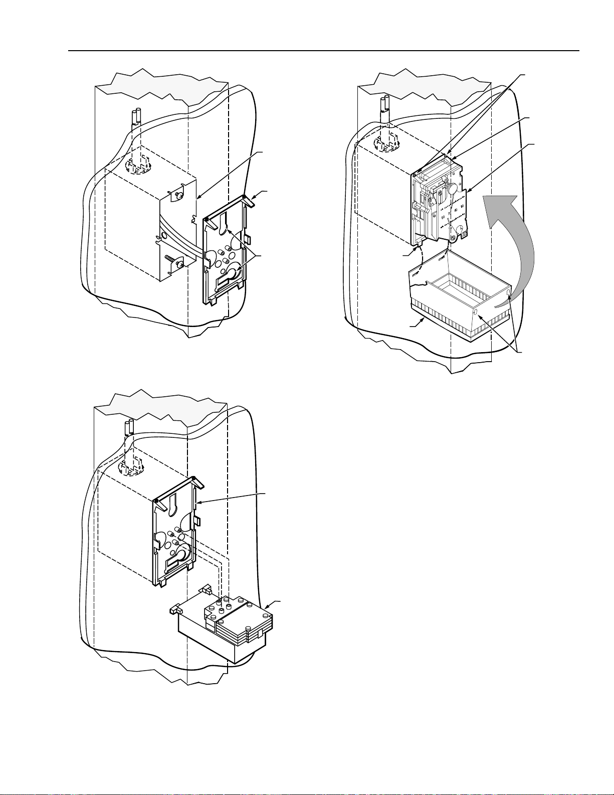
3. Mount Deep Wall Box to stud so that front of Box will be
flush with finished wall.
95-5597—1
C3590
5. After drywall or plaster is up, remove Fitting Finder, if
used, from box. Cut elbow from end of Cable Assembly.
Connect tubing to barbs on stat backplate.
14
Page 15
TP970-72, TP970-74, TP9600, AND TP9630 PNEUMATIC SENSORS, HUMIDISTATS, AND THERMOSTATS
SETSCREWS
STAT
BACKPLATE
DEEP WALL
BOX
STAT
BACKPLATE
KEYHOLE
SLOTS
C3587
6. Back screws out of Deep Wall Box. Hook stat backplate
keyhole slots onto backed-out screws. Level stat
backplate and tighten screws.
STAT
TAB (2)
COVER
SETSCREW
SLOTS
C4115
8. Hook slots on stat cover over bottom tabs on stat
backplate. Swing stat cover up and over stat. Use
Thermostat Tool to raise stat backplate setscrews into
setscrew slots on top of cover.
7. Mount stat onto stat backplate.
STAT
BACKPLATE
STAT
C3575
Mounting to Stud with Standard Electrical Box
Mounting to a stud using a standard electrical box requires
the following equipment:
— Standard Utility Conduit Box CCT2967 (MVE2967) or
Standard 4 x 4 in. Electrical Box CCT2960 (Fig. 27)
— One of the following (Fig. 28):
• Plastic Cable Assembly 14001491-001 (one pipe),
-002 (two pipe), or -003 (three pipe) and Barb
Couplings CCT1606B (MJP1606B) (5/32 x 1/4 in.) or
CCT1628B (MJP1628B) (5/32 x 5/32 in.)
• Copper Cable Assembly 14001494-001 (one pipe),
-002 (two pipe), or -003 (three pipe)
• 1/2 in. emt conduit and 1/2 in. TW Setscrew
Connector CCT2900 (MVE2900)
— Tape Measure CCT422
— No. 10 x 3 Pan Head Sheet Metal Screws CCT2317
(MVH2317) or 2-1/2 in. (64 mm) nails (two per stat)
— Stud Mount Box Clip CCT2642 for Standard Utility
Conduit Box (Fig. 29)
— MFS Clip CCT2649E for Standard 4 x 4 in. Electrical Box
(Fig. 29)
— If wall is to be plastered:
• Standoff Ring 14000885-001
• Fitting Finder 14000706-001
— Thermostat Tool CCT735A (MQT735A)
15
95-5597—1
Page 16

TP970-72, TP970-74, TP9600, AND PNEUMATIC SENSORS, HUMIDISTATS, AND THERMOSTATS
STUD MOUNT BOX CLIP
(FOR STANDARD UTILITY CONDUIT BOX)
STANDARD UTILITY
CONDUIT BOX
4 X 2-1/8 X 1-7/8 IN.
(102 X 55 X 48 MM)
STANDARD
ELECTRICAL BOX
4 X 4 X 2-1/8 IN.
(102 X 102 X 54 MM)
Fig. 27. Standard Utility Conduit Box and
Standard 4 x 4 in. Electrical Box.
MAIN
SWITCH
BRANCH
MAIN
BRANCH
ONE-PIPE ASSEMBLY
THREE-PIPE ASSEMBLY
BARB CAP
BUSHING
MAIN
BRANCH
TWO-PIPE
ASSEMBLY
C3938
BARB TEE
ELBOW
MFS CLIP
(FOR STANDARD 4 X 4 ELECTRICAL BOX)
C3182
Fig. 29. Stud Mount Box Clip and MFS Clip.
TAPE
MEASURE
PROTECTOR
CAP
BARB
COUPLINGS
CABLE ASSEMBLY
FOR PLASTIC
TUBING
OR
1/2 IN. EMT
CONDUIT
1/2 IN. TW
SETSCREW
CONNECTOR
C3563
Fig. 28. One-, Two-, or Three-Pipe Plastic
or Copper Cable Assembly
or
1/2 in. EMT Conduit with 1/2 in. TW Setscrew Connector.
95-5597—1
C3162
1. Measure and mark approximate stat location on stud.
16
Page 17

TP970-72, TP970-74, TP9600, AND TP9630 PNEUMATIC SENSORS, HUMIDISTATS, AND THERMOSTATS
CABLE
STANDARD UTILITY
CONDUIT BOX
NO. 10 X 3 PAN HEAD
SHEET METAL SCREWS
OR 6d 2 IN. (64 MM) NAILS
ASSEMBLY
BUSHING
PUSH BUSHING
INTO KNOCKOUT
MOUNTING STANDARD UTILITY CONDUIT BOX
DIRECTLY TO STUD
STANDARD UTILITY
CONDUIT BOX
MOUNTING STANDARD UTILITY CONDUIT BOX
TO STUD USING STUD MOUNT BOX CLIP
STANDARD 4 x 4
ELECTRICAL BOX
STUD MOUNT
BOX CLIP
1/2 IN. TW
SETSCREW
CONNECTOR
OR
1/2 IN. EMT
CONDUIT
MOUNTING STANDARD 4 x 4 ELECTRICAL BOX
TO STUD USING MFS CLIP
2. Mount box to stud.
MFS
CLIP
C3186
3. Place elbow end of Cable Assembly through knockout
and push Cable Assembly bushing into knockout.
or
Attach 1/2 in. TW Setscrew Connector to appropriate
knockout in box, place conduit into Connector, and
tighten Connector setscrew.
17
C3188
95-5597—1
Page 18

TP970-72, TP970-74, TP9600, AND PNEUMATIC SENSORS, HUMIDISTATS, AND THERMOSTATS
TUBING
BARB
COUPLINGS
CABLE
ASSEMBLY
STANDARD
UTILITY
CONDUIT BOX
STANDOFF RING
(EARS BROKEN OFF)
OR
OR
TUBING
CONDUIT
C3189
4. Remove protector cap from Cable Assembly and attach
plastic tubing to Cable Assembly with 5/32 x 1/4 in. or
5/32 x 5/32 in. Barb Couplings.
or
Run plastic tubing through conduit.
STANDARD 4 x 4
ELECTRICAL BOX
IF WALL IS TO BE PLASTERED:
STANDOFF RING
STANDOFF
RING
95-5597—1
18
FITTING FINDER
5.
Mount Standoff Ring to box with screws provided. For
C3940
standard utility conduit box, break ears off Standoff
Ring before mounting. If wall is to be plastered, snap
Fitting Finder onto Standoff Ring.
Page 19

TP970-72, TP970-74, TP9600, AND TP9630 PNEUMATIC SENSORS, HUMIDISTATS, AND THERMOSTATS
STAT
BACKPLATE
STAT
C3579
STANDOFF
RING IN
WALL
TUBING
STAT
BACKPLATE
C3592
6. After drywall or plaster is up, remove elbow from end of
Cable Assembly, if used. Connect tubing to barbs on
stat backplate.
STANDOFF
RING IN
WALL
STAT
BACKPLATE
KEYHOLE
SLOTS
8. Mount stat onto stat backplate.
TAB (2)
COVER
SETSCREWS
STAT
BACKPLATE
STAT
C3586
7. Back screws out of Standoff Ring. Hook keyhole slots
of stat backplate over screws. Level stat backplate and
tighten screws.
9. Hook slots on stat cover over bottom tabs on stat
backplate. Swing stat cover up and over stat. Use
Thermostat Tool to raise stat backplate setscrews into
setscrew slots on top of cover.
19
SETSCREW
SLOTS
C4117
95-5597—1
Page 20

TP970-72, TP970-74, TP9600, AND PNEUMATIC SENSORS, HUMIDISTATS, AND THERMOSTATS
Mounting to Lath
Mounting to lath requires the following equipment:
— Shallow Wall Plate Assembly 14001615-001/-002 or
14001616-001/-002 (Fig. 30). Includes the following:
• Shallow Wall Plate 14001614-001
• Plaster Ring 14001609-001
• Fitting Finder 14000706-001
TAPE
MEASURE
NOTE: Shallow Wall Plate Assembly 14001615-001 (one
pipe) or -002 (two pipe) has copper tubing.
Assembly 14001616-001 (one pipe) or -002 (two
pipe) has 5/32 in. (4 mm) O.D. plastic tubing.
— Tape Measure CCT422
— Barb Couplings CCT1606B (MJP1606B) (5/32 x 1/4 in.)
or CCT1628B (MJP1628B) (5/32 x 5/32 in.) for plastic
tubing (one, two, or three Couplings required according
to application)
— Soft Copper Tie Wire CCT2643 or Plastic Covered Wire
Ties CCT2663 (MVE2663)
— Wall Mounting Ring 14004458-001
— Thermostat Tool CCT735A (MQT735A)
SHALLOW WALL
PLATE BOTH ENDS
ARE REMOVABLE
PROTECTOR CAP
8 FT (2.5 M)TUBING
AND TWIN ELBOW
ASSEMBLY
1
PLASTER RING
C3170
1. Measure and mark approximate stat location on lath.
1
FITTING FINDER
PRESS TO SNAP
IN PLACE
1
AVAILABLE SEPARATELY
Fig. 30. Shallow Wall Plate Assembly.
C3597
SOFT COPPER TIE WIREOR
PLASTIC COVERED WIRE TIES
C3187
2. At approximate stat location, anchor corners of Shallow
Wall Plate to lath with Soft Copper Tie Wire or Plastic
Covered Wire Ties.
95-5597—1
20
Page 21

TP970-72, TP970-74, TP9600, AND TP9630 PNEUMATIC SENSORS, HUMIDISTATS, AND THERMOSTATS
FITTING
FINDER
PLASTER RING
C3599
TUBING
BARB
C3948
COUPLINGS
TUBING AND
TWIN ELBOW
ASSEMBLY
SHALLOW
WALL PLATE
3. Connect tubing to Tubing and Twin Elbow Assembly
with 5/32 x 1/4 in. or 5/32 x 5/32 in. Barb Couplings.
SHALLOW
WALL PLATE
BREAKOUT TAB
PLASTER
RING
SCREWS
PROVIDED
WITH SHALLOW
WALL PLATE
C3598
5. Remove break-out tab from top of Plaster Ring. Push
Plaster Ring onto Shallow Wall Plate brackets and
lower screw receptacle. Attach Plaster Ring to Shallow
Wall Plate with screws provided.
SOFT COPPER TIE
WIRE OT PLASTIC
COVERED WIRE TIE
SHALLOW
WALL PLATE
TWIN TUBE
TUBING AND TWIN
ELBOW ASSEMBLY
UPPER SCREW
RECEPTACLE
C3949
4. Remove screws from screw receptacles on Shallow 6. Snap Fitting Finder onto Plaster Ring.
Wall Plate. Push Tubing and Twin Elbow Assembly onto
upper screw receptacle. Anchor tubing to lath with Soft
Copper Tie Wire or Plastic Covered Wire Ties.
21
95-5597—1
Page 22

TP970-72, TP970-74, TP9600, AND PNEUMATIC SENSORS, HUMIDISTATS, AND THERMOSTATS
STAT
BACKPLATE
TWIN ELBOW
CONNECTOR
STAT
BACKPLATE
PLASTER RING
IN WALL
C3595
7. After plaster is up, remove Fitting Finder from Plaster
Ring. Remove protector from end of tubing, leaving
Twin Elbow Connector. Connect Twin Elbow Connector
to barbs on stat backplate.
STAT
BACKPLATE
BACKED-OUT
SCREW (2)
KEYHOLE
SLOTS
C3596
STAT
9.
Mount Stat to stat backplate.
TAB (2)
COVER
SETSCREWS
STAT
BACKPLATE
STAT
C3578
8. Back screws out of Plaster Ring. Slip stat backplate
keyhole slots over screws. Level stat backplate and
tighten screws.
95-5597—1
SETSCREW SLOTS
C4118
10. Hook slots on stat cover over bottom tabs on stat
backplate. Swing stat cover up and over stat. Use
Thermostat Tool to raise stat backplate setscrews into
setscrew slots on top of cover.
22
Page 23
TP970-72, TP970-74, TP9600, AND TP9630 PNEUMATIC SENSORS, HUMIDISTATS, AND THERMOSTATS
GUIDE
TAPE
MEASURE
WALL
C3172
LEVEL ON
FLOOR
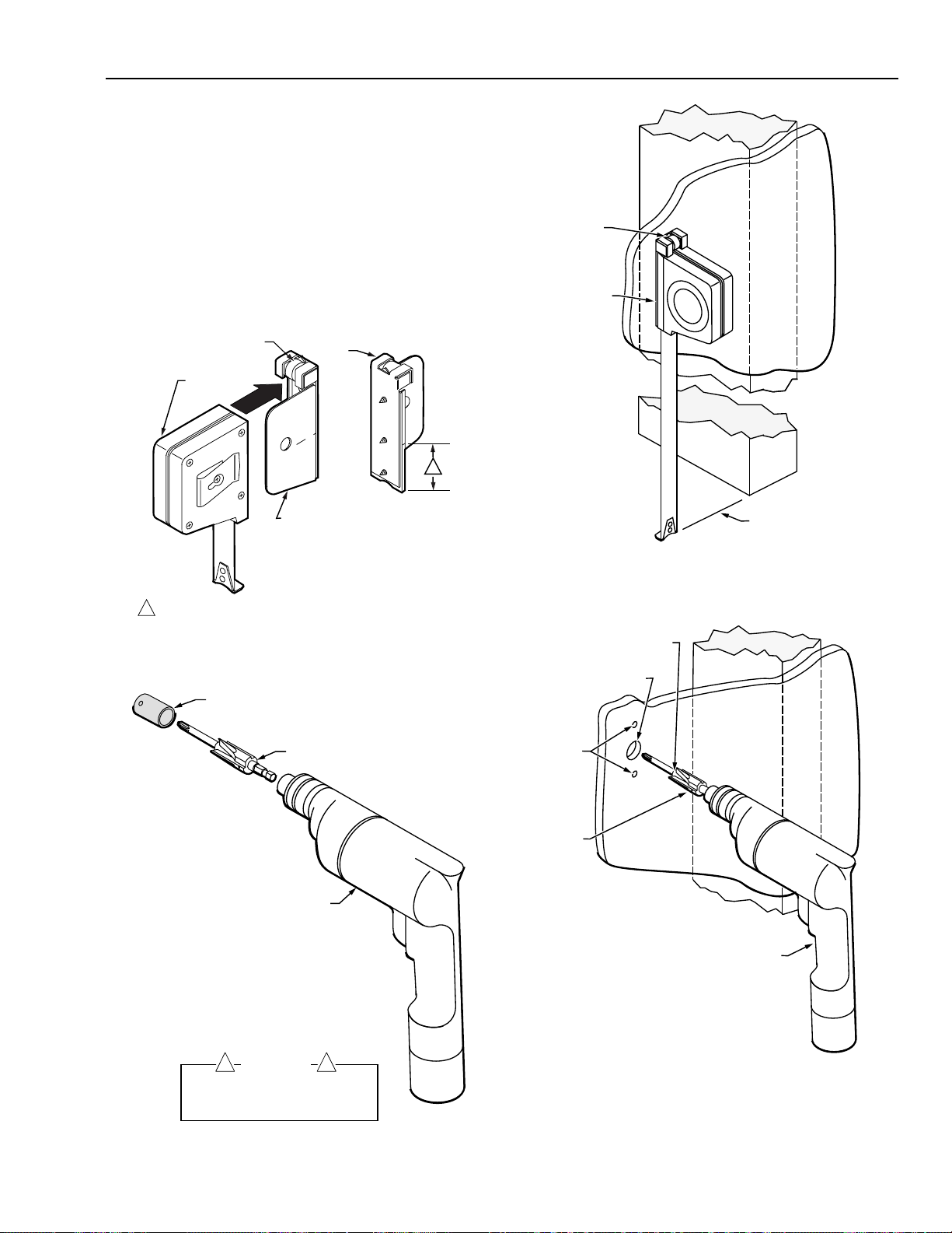
Finished Wall Installation
In a finished wall installation, the studs are covered with
drywall or plaster and the tubing is behind the wall. Finished
wall installation is done with a Quick-Mount Thermostat,
anchors, or a Shallow Wall Plate.
Quick-Mount Thermostat
Installing a Quick-Mount Thermostat requires the following tools:
— Tape Measure CCT422 (Fig. 31)
— Thermostat Mounting Guide Tool CCT690 (Fig. 31)
— Cordless Drill CCT713 (Fig. 32)
— Thermostat Step/Boring Tool CCT691 (Fig. 32)
— Fish Chain CCT417
— Wire hook for pulling Fish Chain (see Step 3)
BACK
VIEW
C
L
1
TAPE
MEASURE
LEVEL
THERMOSTAT
MOUNTING
GUIDE TOOL
1—1/2 IN. (38 MM) FROM BOTTOM OF TAPE MEASURE TO
1
CENTER MARK CORRESPONDING TO CENTER OF STAT.
C3151
Fig. 31. Tape Measure and Thermostat Mounting Guide Tool.
PROTECTIVE SLEEVE FOR BORE
REPLACEMENT PROTECTIVE SLEEVES
ARE AVAILABLE. ORDER CCT691A.
THERMOSTAT STEP/BORING TOOL
CORDLESS DRILL
1. Measure thermostat location on wall. Use level on
Mounting Guide to ensure that Mounting Guide is
plumb. Tap Tape Measure to mark hole locations.
STEP
3/4 INCH
(19 MM)
1/4 INCH
(6 MM)
BORE
CORDLESS DRILL
WARNING
! !
TO AVOID BODILY INJURY AND PROTECT
BORE, LEAVE PROTECTIVE SLEEVE ON
STEP/BORING TOOL EXCEPT WHEN
DRILLING WITH BORE.
C3152
Fig. 32. Thermostat Step/Boring Tool and Cordless Drill.
C3174
2. Drill holes where marked on wall. For top and bottom
holes, drill until the step of the Thermostat Step/Boring
Tool meets wall. For center hole, remove protective
sleeve from bore, force Thermostat Step/Boring Tool
beyond the step, and drill the hole with the bore. Replace
protective sleeve over bore.
23
95-5597—1
Page 24
TP970-72, TP970-74, TP9600, AND PNEUMATIC SENSORS, HUMIDISTATS, AND THERMOSTATS
TWIN
TUBE
WIRE
HOOK
FISH CHAIN
C3175
3. Use Fish Chain to fish tubing through center hole.
ANCHORS
BARBS
BACKPLATE
BACKPLATE
ASSEMBLY
CONE
ASSEMBLY
C3942
5. Cut tubing. Use cone on Backplate Assembly to flare
cut ends of tubing. Connect tubing to barbs on
Backplate Assembly.
BACKPLATE
ASSEMBLY
THERMOSTAT
AND COVER
ASSEMBLY
PACKING
SHELL
4.
Remove Backplate Assembly from packing shell.
C3941
BACKPLATE ASSEMBLY
Place Backplate Assembly anchors through top and
6.
C3173
bottom holes.
95-5597—1
24
Page 25
TP970-72, TP970-74, TP9600, AND TP9630 PNEUMATIC SENSORS, HUMIDISTATS, AND THERMOSTATS
PHILLIPS
END
THERMOSTAT
STEP/BORING
BACKPLATE
ASSEMBLY
C3183
TOOL
CORDLESS DRILL
SHIPPING STOP(S)
C3178
9. Remove shipping stop(s) from Thermostat and Cover
Assembly. Place packing shell and shipping stop(s)
back in carton.
7. Hold Backplate Assembly to appear plumb. With
protective sleeve over bore of Thermostat Step/Boring
Tool, drive anchors with Phillips end of Tool.
BACKPLATE
ASSEMBLY
THERMOSTAT AND
COVER ASSEMBLY
C3176
BACKPLATE
ASSEMBLY
THERMOSTAT AND
COVER ASSEMBLY
C3176
8. Remove Thermostat and Cover Assembly from packing
shell. Align top of Thermostat and Cover Assembly with
top of Backplate. Snap Thermostat and Cover
Assembly onto Backplate Assembly.
10. After painting is complete, use tear strip to remove
outer paint mask. Peel off inner paint mask.
25
95-5597—1
Page 26

TP970-72, TP970-74, TP9600, AND PNEUMATIC SENSORS, HUMIDISTATS, AND THERMOSTATS
WALL
LEVEL ON
GUIDE
TAPE
MEASURE
FLOOR
C3172
Anchors
Drywall installation with anchors requires the following
equipment:
— Tape Measure CCT422 (Fig. 33)
— Thermostat Mounting Guide Tool CCT690 (Fig. 33)
— Cordless Drill CCT713 (Fig. 34)
— Thermostat Step/Boring Tool CCT691 (Fig. 34)
— Fish Chain CCT417
— Wire hook for pulling Fish Chain (see Step 3)
— Molly Anchors CCT2260 (MVH2260) (2 per stat)
— Thermostat Tool CCT735A (MQT735A)
BACK
VIEW
C
L
THERMOSTAT
MOUNTING
GUIDE TOOL
1
TAPE
MEASURE
LEVEL
1—1/2 IN. (38 MM) FROM BOTTOM OF TAPE MEASURE TO
1
CENTER MARK CORRESPONDING TO CENTER OF STAT.
C3151
Fig. 33. Tape Measure and Thermostat Mounting Guide Tool.
PROTECTIVE SLEEVE FOR BORE
REPLACEMENT PROTECTIVE SLEEVES
ARE AVAILABLE. ORDER CCT691A.
THERMOSTAT STEP/BORING TOOL
CORDLESS DRILL
1. Measure thermostat location on wall. Use level on
Mounting Guide to ensure that Mounting Guide is plumb.
Tap Tape Measure to mark hole locations on wall.
STEP
3/4 INCH
(19 MM)
1/4 INCH
(6 MM)
BORE
CORDLESS DRILL
!
WARNING
TO AVOID BODILY INJURY AND PROTECT
BORE, LEAVE PROTECTIVE SLEEVE ON
STEP/BORING TOOL EXCEPT WHEN
DRILLING WITH BORE.
!
C3152
Fig. 34. Thermostat Step/Boring Tool and Cordless Drill.
95-5597—1
C3174
2. Drill holes where marked on wall. For top and bottom
holes, drill until the step of the Thermostat Step/Boring
Tool meets wall. For center hole, remove protective sleeve
from bore, force Thermostat Step/Boring Tool beyond the
step, and drill the hole with the bore. Replace protective
sleeve over bore.
26
Page 27

TP970-72, TP970-74, TP9600, AND TP9630 PNEUMATIC SENSORS, HUMIDISTATS, AND THERMOSTATS
PHILLIPS
END
STAT
BACKPLATE
ANCHOR (2)
THERMOSTAT
STEP/BORING
TOOL
C3171
CORDLESS DRILL
TWIN
TUBE
WIRE
HOOK
TUBING
M3944
FISH CHAIN
C3175
3. Use Fish Chain to fish tubing through center hole.
STAT BACKPLATE
5.
Cut tubing and connect to barbs on stat backplate.
STAT BACKPLATE
MOLLY ANCHORS
KEYHOLE SLOTS
4. Push Molly anchor heads through stat backplate
keyhole slots. Tighten anchors slightly to secure them
to stat backplate.
C3943
6. Push anchors into holes in wall. Level backplate. With
protective sleeve over bore of Thermostat Step/Boring
Tool, tighten anchors with Phillips end of Tool.
27
95-5597—1
Page 28

TP970-72, TP970-74, TP9600, AND PNEUMATIC SENSORS, HUMIDISTATS, AND THERMOSTATS
STAT
BACKPLATE
STAT
7. Mount stat onto stat backplate.
SETSCREWS
STAT
BACKPLATE
C3170
Block or Brick Wall
A stat should be mounted according to the steps shown in
ROUGH-IN INSTALLATION. Use the procedure in FINISHED
WALL INSTALLATION only if the stat cannot be roughed in as
part of the wall. If the wall is to be plastered, see
INSTALLATION WITH SURFACE-MOUNTED TUBING.
Rough-In Installation
Rough-in is done by the mason as the wall is laid. The
installer hangs the stat at its approximate final location and
the mason cuts the hole where needed in the block course.
Rough-in installation may require some or all of the following
equipment:
— Deep Wall Box 14001355-001 (Fig. 35)
— One of the following (Fig. 36):
• Plastic Cable Assembly 14001491-001 (one pipe),
-002 (two pipe), or -003 (three pipe) and Barb
Couplings CCT1606B (MJP1606B) (5/32 x 1/4 in.) or
CCT1628B (MJP1628B) (5/32 x 5/32 in.)
• Copper Cable Assembly 14001494-001 (one pipe),
-002 (two pipe), or -003 (three pipe)
• 1/2 in. emt conduit and 1/2 in. TW Setscrew
Connector CCT2900 (MVE2900)
— Tape Measure CCT422
— Thermostat Tool CCT735A (MQT735A)
STAT
SETSCREW
SLOTS
TAB (2)
COVER
8. Hook slots on stat cover over bottom tabs on stat
backplate. Swing stat cover up and over stat. Use
Thermostat Tool to raise stat backplate setscrews into
setscrew holes on top of cover.
C4114
ALIGNMENT GUIDE
FOR FINISHED WALL
NO. 6–32 X 1/2 IN. SCREW (2)
PROVIDED WITH DEEP WALL BOX
Fig. 35. Deep Wall Box.
C3185
95-5597—1
28
Page 29

TP970-72, TP970-74, TP9600, AND TP9630 PNEUMATIC SENSORS, HUMIDISTATS, AND THERMOSTATS
MAIN
BRANCH
THREE-PIPE ASSEMBLY
ONE-PIPE ASSEMBLY
BUSHING
CABLE ASSEMBLY
OR
MAIN
BRANCH
BARB CAP
MAIN
BRANCH
SWITCH
BARB TEE
ELBOW
TWO-PIPE
ASSEMBLY
PROTECTOR
CAP
BARB
COUPLINGS
FOR PLASTIC
TUBING
CABLE
ASSEMBLY
PUSH BUSHING
INTO KNOCKOUT
DEEP
WALL BOX
1/2 IN. TW
SETSCREW
CONNECTOR
OR
1/2 IN. EMT
CONDUIT
1/2 IN. EMT
CONDUIT
1/2 IN. TW
SETSCREW
CONNECTOR
C3563
Fig. 36. One-, Two-, or Three-Pipe Plastic
or Copper Cable Assembly
or
1/2 in. EMT Conduit with 1/2 in. TW Setscrew Connector.
DEEP
WALL BOX
C3564
1. Place elbow end of Cable Assembly through knockout
and push Cable Assembly bushing into knockout.
or
Attach 1/2 in. TW Setscrew Connector to appropriate
knockout in box, place conduit into Connector, and
tighten Connector setscrew.
29
95-5597—1
Page 30

TP970-72, TP970-74, TP9600, AND PNEUMATIC SENSORS, HUMIDISTATS, AND THERMOSTATS
TUBING
BARB
COUPLINGS
CABLE
ASSEMBLY
CONDUIT
OR
TUBING
HOLLOW BLCOK
OR BRICK WALL
DEEP
WALL BOX
C4101
3. Measure approximate location of stat. Hang or position
Deep Wall Box at measured location.
C3565
2. Remove protector cap from Cable Assembly and attach
plastic tubing to Cable Assembly with 5/32 x 1/4 in. or
5/32 x 5/32 in. Barb Couplings.
or
Run plastic tubing through conduit.
PLASTIC CABLE
COPPER
TUBING
CONDUIT
DEEP WALL BOX
ASSEMBLIES
C4102
4. Mason lays block or brick course and cuts hole where
indicated by stat position. Place Deep Wall Box
Assembly into hole so that conduit or Cable Assembly
runs through openings inside blocks or bricks.
95-5597—1
30
Page 31

TP970-72, TP970-74, TP9600, AND TP9630 PNEUMATIC SENSORS, HUMIDISTATS, AND THERMOSTATS
7. Mount stat to stat backplate.
8. Hook slots on stat cover over bottom tabs on stat
DEEP WALL
BOX IN BLOCK
BRICK WALL
backplate. Swing stat cover up and over stat. Use
Thermostat Tool to raise stat backplate setscrews into
setscrew slots on top of cover.
Finished Wall Installation
This section describes finished wall installation with tubing
recessed in the openings inside the block or brick. To install a
stat where tubing is surface mounted, see SURFACEMOUNTED TUBING.
C3582
5. If Cable Assembly is used, cut elbow from end of
tubing. Connect tubing to barbs on stat backplate.
DEEP WALL
BOX SCREW (2)
STAT
BACKPLATE
Finished wall installation requires the following equipment:
— Tape Measure CCT422 (Fig. 37)
— Thermostat Mounting Guide Tool CCT690 (Fig. 37)
— Fish Chain CCT417
— Wire hook for pulling Fish Chain through wall (see Step 4)
— 1/2 in. Hammer Drill CCT717 (MQG717) (Fig. 38)
— Masonry Drills CCT773 (MQG773) (3/16-in. bit) and
CCT786 (7/8-in. bit) (Fig. 38)
— 3/4 in. Plastic Screw Anchors CCT2230 (MVH2230)
(2 per stat)
— No. 8 sheet metal screws (2 per stat)
— Thermostat Tool CCT735A (MQT735A)
BACK
VIEW
C
L
THERMOSTAT
MOUNTING
GUIDE TOOL
1
TAPE
MEASURE
LEVEL
KEYHOLE
SLOT (2)
STAT BACKPLATE
C3583
6. Back screws out of Deep Wall Box. Hook keyhole slots
on stat backplate over backed out screws. Level stat
backplate and tighten screws.
1—1/2 IN. (38 MM) FROM BOTTOM OF TAPE MEASURE TO
1
CENTER MARK CORRESPONDING TO CENTER OF STAT.
C3151
Fig. 37. Tape Measure and Thermostat Mounting Guide Tool.
31
95-5597—1
Page 32

TP970-72, TP970-74, TP9600, AND PNEUMATIC SENSORS, HUMIDISTATS, AND THERMOSTATS
MASONRY DRILL
MASONRY DRILL
(7/8 -IN. BIT)
HAMMER DRILL
C3191
Fig. 38. Hammer Drill and 3/16-in. or 7/8-in. Masonry Drill.
TAPE MEASURE
THERMOSTAT
MOUNTING
GUIDE TOOL
HAMMER DRILL
C3196
2. Use 7/8-in. Masonry Drill and Hammer Drill to Drill
7/8-in. (22.2-mm) center hole.
1. Measure approximate stat location on wall. Turn Tape
Measure sideways and mark center, top, and bottom
hole locations according to points on back of
Thermostat Mounting Guide Tool.
95-5597—1
C3195
32
Page 33

TP970-72, TP970-74, TP9600, AND TP9630 PNEUMATIC SENSORS, HUMIDISTATS, AND THERMOSTATS
MASONRY DRILL
3/16 IN.
(4.8 MM)
PLASTIC SCEW
ANCHOR (2)
(3/16-IN. BIT)
PLASTIC SCREW
ANCHOR (2)
HAMMER
DRILL
C3199
3. Use 3/16-in. Masonry Drill to drill 3/16-in. (4.8-mm) top
and bottom holes.
WIRE HOOK
NO. 8 SHEET
METAL SCREWS (2)
C3197
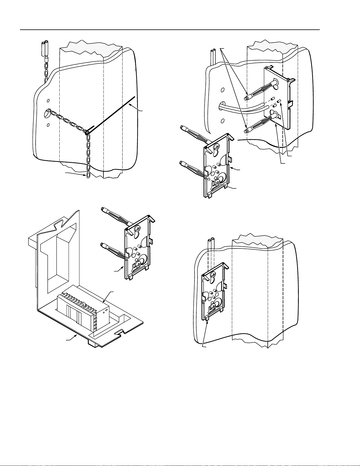
5. Knot tubing. Tap 3/4 in. Plastic Screw Anchors into top
and bottom holes. Screw No. 8 sheet metal screws
partway into Plastic Screw Anchors.
STAT
BACKPLATE
FISH CHAIN
4. Use Fish Chain to fish tubing through center hole.
C4104
6. Unknot tubing and connect to barbs on stat backplate.
33
C4107
95-5597—1
Page 34

TP970-72, TP970-74, TP9600, AND PNEUMATIC SENSORS, HUMIDISTATS, AND THERMOSTATS
9. Hook slots on stat cover over bottom tabs on stat
backplate. Swing stat cover up and over stat. Use
Thermostat Tool to raise stat backplate setscrews into
setscrew slots on top of cover.
Concrete Pour
Mounting in preparation for a concrete pour requires the
following equipment:
STAT
BACKPLATE
KEYHOLE
SLOTS
— Deep Wall Box 14001355-001 (Fig. 39)
— One of the following (Fig. 40):
• Plastic Cable Assembly 14001491-001 (one pipe),
-002 (two pipe), or -003 (three pipe) and Barb
Couplings CCT1606B (MJP1606B) (5/32 x 1/4 in.) or
CCT1628B (MJP1628B) (5/32 x 5/32 in.)
• Copper Cable Assembly 14001494-001 (one pipe),
-002 (two pipe), or -003 (three pipe)
• 1/2 in. emt conduit and 1/2 in. TW Setscrew
Connector CCT2900 (MVE2900)
— Tape Measure CCT422
— Soft Copper Tie Wire CCT2643 or Plastic Covered Wire
Ties CCT2663 (MVE2663)
— 2 in. Duct Tape CCT3349B
— Thermostat Tool CCT735A (MQT735A)
C4108
7. Hook keyhole slots of stat backplate over screws. Level
stat backplate and tighten screws.
STAT
BACKPLATE
STAT
ALIGNMENT GUIDE
FOR FINISHED WALL
NO. 6–32 X 1/2 IN. SCREW (2)
PROVIDED WITH DEEP WALL BOX
Fig. 39. Deep Wall Box.
C3185
8. Mount stat to stat backplate.
95-5597—1
C3572
34
Page 35

TP970-72, TP970-74, TP9600, AND TP9630 PNEUMATIC SENSORS, HUMIDISTATS, AND THERMOSTATS
MAIN
BRANCH
THREE-PIPE ASSEMBLY
ONE-PIPE ASSEMBLY
BUSHING
CABLE ASSEMBLY
OR
MAIN
BRANCH
BARB CAP
MAIN
BRANCH
SWITCH
BARB TEE
ELBOW
TWO-PIPE
ASSEMBLY
PROTECTOR
CAP
BARB
COUPLINGS
FOR PLASTIC
TUBING
STEEL REINFORCEMENT ROD
TAPE
MEASURE
C3164
1. Measure and mark stat location on steel reinforcement
rods.
1/2 IN. EMT
CONDUIT
1/2 IN. TW
SETSCREW
CONNECTOR
C3563
Fig. 40. One-, Two-, or Three-Pipe Plastic
or Copper Cable Assembly
or
1/2 in. EMT Conduit with 1/2 in. TW Setscrew Connector.
35
95-5597—1
Page 36

TP970-72, TP970-74, TP9600, AND PNEUMATIC SENSORS, HUMIDISTATS, AND THERMOSTATS
CABLE ASSEMBLY
OR CONDUIT
TAPE
DEEP
WALL BOX
C3166
CABLE
ASSEMBLY
PUSH BUSHING
INTO KNOCKOUT
DEEP
WALL BOX
1/2 IN. TW
SETSCREW
CONNECTOR
OR
1/2 IN. EMT
CONDUIT
TUBING
BARB
COUPLINGS
CABLE
ASSEMBLY
CONDUIT
OR
TUBING
DEEP
WALL BOX
C3564
2. Place elbow end of Cable Assembly through knockout
and push Cable Assembly bushing into knockout.
or
Attach 1/2 in. TW Setscrew Connector to appropriate
knockout in box, place conduit into Connector, and
tighten Connector setscrew.
C3565
3. Run plastic tubing through conduit, or remove protector
cap from Cable Assembly and attach plastic tubing to
Cable Assembly with 5/32 x 1/4 in. or 5/32 x 5/32 in.
Barb Couplings.
95-5597—1
4. Wrap Deep Wall Box with 2 in. Duct Tape.
36
Page 37

TP970-72, TP970-74, TP9600, AND TP9630 PNEUMATIC SENSORS, HUMIDISTATS, AND THERMOSTATS
SOFT COPPER TIE
WIRE OR PLASTIC
COVERED WIRE TIE
STEEL
REINFORCEMENT
ROD
TAPED DEEP WALL BOX
POSITION SO THAT
FRONT OF BOX WILL
BE FLUSH WITH WALL
C3165
5. Attach conduit or Cable Assembly to steel
reinforcement rods with Soft Copper Tie Wire or Plastic
Covered Wire Ties so that front of Deep Wall Box will
be flush with wall.
DEEP WALL BOX
STAT BACKPLATE
C3585
7. Back screws out of Deep Wall Box. Hook stat backplate
keyhole slots onto backed-out screws. Level stat
backplate and tighten screws.
DEEP WALL BOX
STAT BACKPLATE
C3584
6. After concrete is poured and set, cut tape from front of
Deep Wall Box. Cut elbow from Cable Assembly, if
used. Connect tubing to barbs on stat backplate.
STAT BACKPLATE
C3577
8. Mount stat onto stat backplate.
37
STAT
95-5597—1
Page 38

TP970-72, TP970-74, TP9600, AND PNEUMATIC SENSORS, HUMIDISTATS, AND THERMOSTATS
SETSCREWS
STAT
BACKPLATE
STAT
TAB (2)
UNI-BIT
1/8 IN. HIGH SPEED
DRILL BIT
CORDLESS DRILL
COVER
SETSCREW SLOTS
C4119
9. Hook slots on stat cover over bottom tabs on stat
backplate. Swing stat cover up and over stat. Use
Thermostat Tool to raise stat backplate setscrews into
setscrew slots on top of cover.
Mullion
Mounting to a standard metal mullion requires the following
equipment:
— Tape Measure CCT422 (Fig. 41)
— Thermostat Mounting Guide Tool CCT690 (Fig. 41)
— Fish Chain CCT417
— Wire hook for pulling Fish Chain through wall (see Step 4)
— Cordless Drill CCT713 (Fig. 42)
— Uni-Bit CCT230 (Fig. 42)
— 1/8 in. High-Speed Drill Bit CCT166 (MQG166) (Fig. 42)
— No. 8 x 3/4 in. Sheet Metal Screws CCT2306 (MVH2306)
— Thermostat Tool CCT735A (MQT735A)
BACK
VIEW
TAPE
MEASURE
LEVEL
C3168
Fig. 42. Unit-Bit, 1/8 in. High-Speed Drill Bit,
and Cordless Drill.
MULLION
THERMOSTAT
MOUNTING
GUIDE TOOL
TAPE MEASURE
C
L
1
THERMOSTAT
MOUNTING
GUIDE TOOL
1—1/2 IN. (38 MM) FROM BOTTOM OF TAPE MEASURE TO
1
CENTER MARK CORRESPONDING TO CENTER OF STAT.
C3151
Fig. 41. Tape Measure and Thermostat Mounting Guide Tool.
95-5597—1
C3192
1. Measure approximate stat location on mullion. Turn
Tape Measure sideways and mark center, top, and
bottom hole locations according to points on back of
Thermostat Mounting Guide Tool.
38
Page 39

TP970-72, TP970-74, TP9600, AND TP9630 PNEUMATIC SENSORS, HUMIDISTATS, AND THERMOSTATS
WIRE HOOK
C4103
FISH CHAIN
TUBING
STAT BACKPLATE
C4106
7/8 IN. (22 MM)
UNI-BIT
CORDLESS DRILL
C3193
2.
Use Uni-Bit and Cordless Drill to drill 7/8-in. (22-mm)
center hole.
1/8 IN. (3.2 MM)
1/8 IN. HIGH SPEED
DRILL BIT
4.
Use Fish Chain to fish tubing through center hole.
CORDLESS DRILL
C3194
3. Use 1/8 in. High-Speed Drill Bit to drill 1/8-in. (3.2-mm)
top and bottom holes.
5. Attach tubing to barbs on stat backplate.
39
95-5597—1
Page 40

TP970-72, TP970-74, TP9600, AND PNEUMATIC SENSORS, HUMIDISTATS, AND THERMOSTATS
STAT BACKPLATE
NO. 8 x 3/4 SHEET
METAL SCREW (2)
C4105
6. Position stat backplate against mullion. Level stat
backplate. Screw No. 8 x 3/4 in. Sheet Metal Screws
through stat backplate keyhole slots into mullion.
STAT BACKPLATE
SETSCREWS
STAT BACKPLATE
STAT
TAB (2)
COVER
SETSCREW SLOTS
C4111
8. Hook slots on stat cover over bottom tabs on stat
backplate. Swing stat cover up and over stat. Use
Thermostat Tool to raise stat backplate setscrews into
setscrew slots on top of cover.
7. Mount stat to stat backplate.
STAT
C3574
Installation With Surface-Mounted Tubing
Installation with surface-mounted tubing requires the following
equipment:
— Shallow Wall Plate Assembly 14001615-001/-002 or
14001616-001/-002 (Fig. 43). Includes the following:
• Shallow Wall Plate 14001614-001
• Plaster Ring 14001609-001
• Fitting Finder 14000706-001
NOTE: Shallow Wall Plate Assembly 14001615-001 (one
pipe) or -002 (two pipe) has copper tubing.
Assembly 14001616-001 (one pipe) or -002 (two
pipe) has 5/32 in. (4 mm) O.D. plastic tubing.
— Tape Measure CCT422
— Wall Mounting Ring 14004458-001 (Fig. 44)
— Cordless Hammer Drill CCT712 (MQG773) (Fig. 45)
— If wall is block, brick, or concrete:
• Masonry Drill CCT773 (MQG773) (Fig. 45)
• Plastic Screw Anchors CCT2230 (MVH2230)
(two per stat)
• No. 8 x 3/4 in. Sheet Metal Screws CCT2306
(MVH2306) (two per stat)
— If wall is drywall, Sheetrock, or plaster:
• Thermostat Step/Boring Tool CCT691 (Fig. 45)
• Molly Anchors CCT2260 (MVH2260) (two per stat)
— Pocket knife
— Thermostat Tool CCT735A (MQT735A)
95-5597—1
40
Page 41
TP970-72, TP970-74, TP9600, AND TP9630 PNEUMATIC SENSORS, HUMIDISTATS, AND THERMOSTATS
THERMOSTAT
STEP/BORING TOOL
CORDLESS
HAMMER DRILL
C3190
MASONARY DRILL
SHALLOW WALL
PLATE BOTH ENDS
ARE REMOVABLE
1
AVAILABLE SEPARATELY
Fig. 43. Shallow Wall Plate Assembly.
PROTECTOR CAP
8 FT (2.5 M)TUBING
AND TWIN ELBOW
ASSEMBLY
1
FITTING FINDER
PRESS TO SNAP
IN PLACE
1
PLASTER RING
C3597
REMOVABLE WEB
(CUT AWAY WITH
POCKET KNIFE)
2-5/16
(59)
1/2
(13)
3-17/32
(90)
C3153
Fig. 45. Masonry Drill, Thermostat Step/Boring Tool,
and Cordless Hammer Drill.
TAPE
MEASURE
C3163
Fig. 44. Wall Mounting Ring.
1. Measure and mark stat location on wall.
41
95-5597—1
Page 42

TP970-72, TP970-74, TP9600, AND PNEUMATIC SENSORS, HUMIDISTATS, AND THERMOSTATS
3. If wall is:
a. Block, brick, or concrete, use Cordless Hammer
Drill and Masonry Drill to drill 3/16-in. (4.8-mm)
holes where marked. Tap Plastic Screw Anchors
into holes.
STEP
THERMOSTAT STEP/BORING TOOL
SAMPLE ANCHOR
LOCATIONS
CORDLESS DRILL
SHALLOW WALL PLATE
(ENDS BROKEN OFF)
C3184
2. Break off ends of Shallow Wall Plate. Center Shallow
Wall Plate over mark on wall. Mark anchor locations at
two opposite corners of Shallow Wall Plate.
3/16 IN.
(4.8 MM)
PLASTIC SCREW
MASONRY
DRILL BIT
ANCHOR (2)
C3169
b. Drywall, Sheetrock, or plaster, leave protective
sleeve over bore of Thermostat Step/Boring Tool
and use Drill and Tool to drill 1/4 in. (6 mm) holes
where marked (drill up to step on Tool).
PLASTIC SCREW
ANCHOR (2)
SHALLOW
WALL PLATE
95-5597—1
CORDLESS
HAMMER DRILL
C3196
C3200
4. If wall is:
a. If wall is block, brick, or concrete, screw No. 8 x 3/4
in. Sheet Metal Screws through stat backplate and
into Plastic Screw Anchors.
42
Page 43

TP970-72, TP970-74, TP9600, AND TP9630 PNEUMATIC SENSORS, HUMIDISTATS, AND THERMOSTATS
TUBING AND TWIN
ELBOW ASSEMBLY
SHALLOW
WALL PLATE
WALL MOUNTING
RING
C3951
TUBING AND TWIN
ELBOW ASSEMBLY
PHILLIPS END
THERMOSTAT
STEP/BORING
TOOL
CORDLESS
HAMMER
DRILL
SHALLOW
WALL PLATE
C3947
MOLLY ANCHORS (2)
b. If wall is drywall, Sheetrock, or plaster,
disassemble Molly anchors and reassemble
through appropriate corner holes of Shallow Wall
Plate (see inset). Tighten anchors slightly to
secure them to Shallow Wall Plate. Push anchors
through holes in wall. With protective sleeve over
bore of Thermostat Step/Boring Tool, use Phillips
end of Tool to tighten anchors.
STRAIN RELIEF
SHALLOW WALL PLATE
C3950
6. Remove screw from Shallow Wall Plate upper screw
receptacle. Push strain relief of Tubing and Twin Elbow
Assembly onto screw receptacle. Replace screw,
leaving it slightly backed out. Back out bottom screw.
TUBING
BARB
COUPLINGS
TUBING AND TWIN
ELBOW ASSEMBLY
PROTECTOR
CAP
PROTECTOR
ASSEMBLY
C3591
5. Remove protector cap and protector assembly from
Tubing and Twin Elbow Assembly. Attach tubing.
7. Use pocket knife to cut away web where indicated
inside Wall Mounting Ring (see inset). Place Wall
Mounting Ring over Shallow Wall Plate and Tubing and
Twin Elbow Assembly.
43
95-5597—1
Page 44

TP970-72, TP970-74, TP9600, AND PNEUMATIC SENSORS, HUMIDISTATS, AND THERMOSTATS
TUBING AND TWIN
ELBOW ASSEMBLY
STAT
BACKPLATE
STAT
BACKPLATE
STAT
C3593
8. Connect Twin Elbow Connector to barbs on stat
backplate.
BACKED-OUT
SCREW (2)
STAT
BACKPLATE
KEYHOLE
SLOTS
C3594
10. Mount stat onto stat backplate.
SETSCREWS
C3581
STAT
BACKPLATE
STAT
9. Hook keyhole slots of stat backplate over backed-out
screws. Level stat backplate and tighten screws.
95-5597—1
44
TAB (2)
COVER
11.
Hook slots on stat cover over bottom tabs on stat
SETSCREW SLOTS
backplate. Swing stat cover up and over stat. Use
Thermostat Tool to raise stat backplate setscrews into
setscrew slots on top of cover.
C4113
Page 45

TP970-72, TP970-74, TP9600, AND TP9630 PNEUMATIC SENSORS, HUMIDISTATS, AND THERMOSTATS
Piping
Figures 46 and 47 show typical one-pipe and two-pipe
applications.
STAT
THERMOSTAT TOOL
M
VALVE
C3159
Fig. 46. Typical One-Pipe Application.
STAT
20
15
10
5
0
25
30
TEST THERMOMETER
GAGE PORT NEEDLE
120
140
100
160
80
180
60
200
40
220
20
0
BM
M
VALVE
C3160
Fig. 47. Typical Two-Pipe Application.
CALIBRATION
Tools Required
Calibration requires the following tools, shown in Figure 48:
— Thermostat Tool CCT735A (MQT735A)
— Gage 305965 (0 to 30 psi [0 to 210 kPa])
— Gage Port Needle CCT729 (MQP729)
— Digital Relative Humidity Indicator Pen CCT915 for
humidistats and humidity sensors
— Test Thermometer CCT902 (MQT902) for thermostats
and temperature sensors
GAGE
DIGITAL RELATIVE
HUMIDITY INDICATOR PEN
C3929
Fig. 48. Humidistat/Humidity Sensor Calibration Tools.
Humidistat/Humidity Sensor
General
After installing the humidistat, set the humidistat to the
desired setpoint and let the system operate long enough to
stabilize. The length of time required for stabilization depends
on system response time and could be only a few minutes or
as long as several hours. Verify that the system has stabilized
before checking calibration.
NOTE: Humidistats and humidity sensors are factory
calibrated and should require only a bleed-off check
to ensure correct operation. The throttling range is
factory set and should not require adjustment under
normal operating conditions.
45
95-5597—1
Page 46

TP970-72, TP970-74, TP9600, AND PNEUMATIC SENSORS, HUMIDISTATS, AND THERMOSTATS
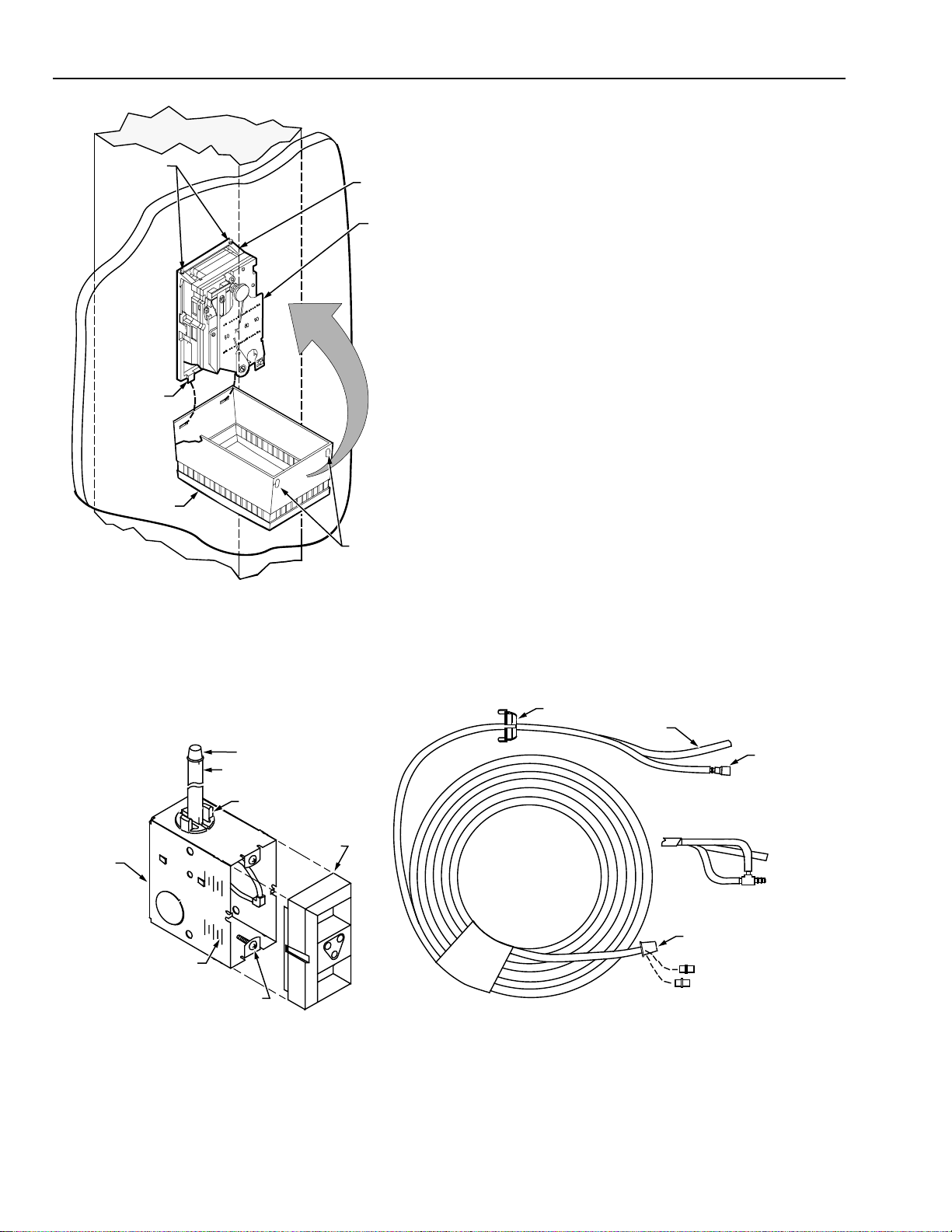
Figure 49 shows humidistat components.
GAGE TAP
BIAS SPRING
THROTTLING
RANGE
ADJUSTMENT
SETPOINT
INDICATOR
CALIBRATION
SCREW
SETPOINT
LOCK SCREW
757065 80 85 90 95
SETPOINT
LOCKING STOPS
SETPOINT
ADJUSTMENT
ELEMENT
SPRING
THROTTLING
RANGE SCALE
SCALE PLATE
NYLON
ELEMENT
C3945
Fig. 49. Humidistat Front View, Cover Off.
Setpoint Lock
To set the minimum and maximum setpoint, refer to Figure 49
and use the following procedure:
1. Loosen setpoint lock screw.
2. Move locking stop to desired position.
3. Tighten setpoint lock screw.
4. Move setpoint adjustment to check stop positioning.
Throttling Range Adjustment (HP970 and HP972)
Use the following procedure if a change in the throttling range
(TR) is required:
1. Slide TR indicator to desired setting on TR scale (see
table).
2. Recalibrate humidistat (see RECALIBRATION).
Throttling Range Adjustment.
Humidistat
Setpoint
Model (% RH)
Range
Minimum Maximum
Throttling Range
Indication Lines (% RH)
HP970 12-75 3 5 10 15
HP970 65-95 3 5 10 15
HP972 15-75 8 12 20 35
Calibration Check
Direct-Acting Humidistat (HP970A)
1. Use Thermostat Tool to remove humidistat cover.
2. Use Digital Relative Humidity Indicator Pen to measure
actual relative humidity (rh) of space.
3. Turn setpoint indicator down 10 percent below
measured rh.
4. Allow humidistat to build up branchline pressure.
5. Turn setpoint indicator up slowly.
6. If humidistat bleeds off at ±3 percent rh of measured
humidity, no further calibration is necessary. Remove
Gage and replace humidistat cover.
7. If humidistat does not operate as described in Step 6,
recalibrate humidistat (see RECALIBRATION).
Reverse-Acting Humidistats (HP970B and HP972)
1. Use Thermostat Tool to remove humidistat cover.
2. Use Digital Relative Humidity Indicator Pen to measure
actual relative humidity (rh) of space.
3. Turn setpoint indicator up 10 percent above measured rh.
4. Allow humidistat to build up branchline pressure.
5. Turn setpoint indicator down slowly.
6. If humidistat bleeds off at ±3 percent rh of measured
humidity, no further calibration is necessary. Remove
Gage and replace humidistat cover.
7. If humidistat does not operate as described in Step 6,
recalibrate humidistat (see RECALIBRATION).
Recalibration
CAUTION
Humidistats are extremely sensitive. Handle
humidistats carefully during recalibration.
HP970 and HP972
The procedure in this section assumes that a calibration
check has been performed (see CALIBRATION CHECK) and
that the humidistat has not operated correctly.
1. Start with main air pressure at 18 psi (124 kPa)
nominal or system pressure between 13 and 18 psi
(91 and 124 kPa).
2. Assemble Gage and Gage Port Needle.
3. Insert Gage Port Needle in humidistat gage tap.
4. Set humidity setpoint indicator at humidity measured
during CALIBRATION CHECK procedure.
5. Turn calibration screw until Gage reads 0 psi.
6. Turn calibration screw in opposite direction until Gage
reads 8 psi (55 kPa) ±1 psi (±7 kPa).
7. Allow 5 to 10 seconds for HP970, 30 to 60 seconds for
HP972, for complete response. Setpoint and actual rh
should be within acceptable limits.
8. Repeat appropriate procedure under CALIBRATION
CHECK to verify calibration.
9. Remove Gage and replace cover.
10. Adjust humidistat setpoint indicator to desired setpoint.
HP971 Humidity Sensor
1. Supply sensor with 18 psi (124 kPa) air through 0.007-in.
internal or external restriction. The HP971A1024 (15 to
85% range) also has a 0.005-in. bleed restriction in the
output line.
2. Assemble Gage and Gage Port Needle.
3. Insert Gage Port Needle in sensor gage tap (same
location as humidistat gage tap shown in Fig. 49).
4. Allow sensor to acclimate to ambient conditions at least
20 minutes.
5. Use Digital Relative Humidity Indicator Pen to measure
actual relative humidity (rh) of space.
6. Adjust calibration screw (same location as humidistat
calibration screw shown in Fig. 49) until branchline
pressure is below that specified in the following table:
95-5597—1
46
Page 47

TP970-72, TP970-74, TP9600, AND TP9630 PNEUMATIC SENSORS, HUMIDISTATS, AND THERMOSTATS
Output Pressure in psi (kPa)
% rh
Range:
15 to 75%
15 to 85%
HP971A1024* 65 to 95%
15 3.0 (21) 3.0 (21) —
20 3.5 (24) 3.9 (27) —
25 4.2 (29) 4.7 (32) —
30 4.9 (34) 5.6 (39) —
35 5.8 (40) 6.4 (44) —
40 6.8 (47) 7.3 (50) —
45 7.8 (54) 8.1 (56) —
50 8.9 (61) 9.0 (62) —
55 10.0 (69) 9.9 (68) —
60 11.1 (77) 10.7 (74) —
65 12.3 (85) 11.6 (80) 3.0 (21)
70 13.6 (94) 12.4 (85) 4.0 (28)
75 15.0 (103) 13.3 (92) 5.3 (37)
80 — 14.1 (97) 7.5 (52)
85 — 15.0 (103) 10.3 (71)
90 — — 13.1 (90)
95 — — 15.0 (103)
* Has a 0.007-in. restriction, and a 0.05-in. bleed restriction in
output line.
7. Readjust calibration screw slowly until pressure is
correct ±0.5 psi for the measured ambient humidity.
8. Remove Gage and replace cover.
Thermostat/Temperature Sensor
General
After installing the thermostat, set the thermostat to the desired
setpoint and let the system operate long enough to stabilize.
The length of time required for stabilization depends on system
response time and could be only a few minutes or as long as
several hours. Verify that the system has stabilized before
checking calibration.
NOTE: Thermostats and temperature sensors are factory
Figure 50 shows thermostat components.
calibrated and should require only a bleed-off check to
ensure correct operation. The throttling range is factory
set and should not require adjustment under normal
operating conditions.
GAGE TAP
BIAS SPRING
Throttling Range Adjustment
1. Use Thermostat Tool to remove cover. Assemble Gage
and Gage Port Needle.
2. Insert Gage Port Needle in thermostat gage tap.
3. Slide throttling range (TR) adjustment to desired
position on TR scale.
4. Mechanically check TR by moving setpoint indicator to
determine difference in setpoint indication when
branchline pressure reads 3 psi (21 kPa) and 13 psi
(91 kPa).
NOTE: If required, turn calibration screw to adjust TR into
thermostat range.
5. Reset TR to within ±2 degrees F (±1 degrees C) of
required setting.
6. Follow applicable procedure under CALIBRATION
CHECK.
Calibration Check
Direct-Acting Thermostat
1. Use Test Thermometer to measure actual temperature
of space.
2. Turn setpoint indicator down to 5 degrees F (2.8 degrees
C) below room temperature.
3. Wait 5 to 10 seconds (30 to 60 seconds for TP973) to
allow thermostat to build up branchline pressure.
4. Turn setpoint indicator up slowly.
5. If thermostat begins to bleed off between 1 degree F
(0.6 degrees C) and 3 degrees F (1.7 degrees C) below
room temperature, no recalibration is necessary. If
recalibration is needed, see RECALIBRATION.
Reverse-Acting Thermostat
1. Use Test Thermometer to measure actual temperature
of space.
2. Turn setpoint indicator up to 5 degrees F (2.8 degrees
C) above room temperature.
3. Wait 5 to 10 seconds (30 to 60 seconds for TP973) to
allow thermostat to build up branchline pressure.
4. Turn setpoint indicator down slowly.
5. If thermostat begins to bleed off between 1 degree F
(0.6 degrees C) and 3 degrees F (1.7 degrees C)
above room temperature, no further calibration is
necessary. If recalibration is needed, see
RECALIBRATION.
THROTTLING
RANGE
ADJUSTMENT
SETPOINT
INDICATOR
CALIBRATION
SCREW
SETPOINT
LOCK SCREW
SETPOINT
LOCKING STOPS
757065 80 85 90 95
SETPOINT
ADJUSTMENT
Fig. 50. Thermostat Front View, Cover Off.
ELEMENT
SPRING
THROTTLING
RANGE SCALE
SCALE PLATE
NYLON
ELEMENT
C3945
Recalibration
The procedures in this section assume that a calibration
check has been performed (see CALIBRATION CHECK) and
that the thermostat has not operated correctly.
NOTE: Thermostats have either an adhesive paper dot or
an antihum spring, as shown in Figure 50. Verify that
either the adhesive paper dot is in place or the
antihum spring just touches the throttling plate and is
not wedged against it. If the antihum spring needs
adjustment, see TP970 Series Pneumatic
Thermostats Service Data 75-7134.
CAUTION
Excessive handling during calibration can heat the
thermostat and cause an inaccurate reading.
47
95-5597—1
Page 48

TP970-72, TP970-74, TP9600, AND PNEUMATIC SENSORS, HUMIDISTATS, AND THERMOSTATS
General Procedure (All Thermostats)
1. Use Test Thermometer to measure actual temperature of
space.
2. Use Thermostat Tool to remove thermostat cover.
Assemble Gage and Gage Port Needle.
3. Insert Gage Port Needle into thermostat gage tap.
4. Turn setpoint adjustment until setpoint indicator reads
measured room temperature.
5. Proceed to appropriate section following.
TP970 and TP9600 Thermostats
1. Turn calibration screw until Gage reads 0 psi.
2. Turn calibration screw in opposite direction until Gage
reads 8 psi (56 kPa) ±1 psi (±7 kPa).
3. Remove Gage. Set thermostat at desired temperature.
Replace thermostat cover.
TP971 and TP9610 Thermostats
1. With main air at pressure specified for DAY operation,
turn DAY calibration screw until Gage reads 0 psi.
2. Turn calibration screw in opposite direction until Gage
reads 8 psi (56 kPa) ±1 psi (±7 kPa).
3. With main air at pressure specified for NITE operation,
rotate NITE setpoint dial until setting agrees with
measured temperature.
4. Repeat Steps 1 and 2 using NITE calibration screw.
5. Remove Gage. Turn setpoint adjustment until setpoint
indicator reads desired room temperature.
6. Replace thermostat cover.
TP972 and TP9620 Thermostats
1. With main air at pressure specified for SUMMER
operation, turn SUMMER calibration screw until Gage
reads 0 psi.
2. Turn calibration screw in opposite direction until Gage
reads 8 psi (56 kPa) ±1 psi (±7 kPa).
3. With main air at pressure specified for WINTER
operation, rotate WINTER setpoint dial until setting
agrees with measured temperature.
4. Repeat Steps 1 and 2 using WINTER calibration screw.
4. Remove Gage. Turn setpoint adjustment until setpoint
indicator reads desired room temperature.
5. Replace thermostat cover.
TP973 and TP9630 Room Thermostat
Follow procedure under TP970 AND TP9600 THERMOSTATS.
TP974 Temperature Sensor
Field calibration is not recommended.
Removing Stat from Conventional Backplate
1. Move backplate tab outward (Fig. 51), using
Thermostat Tool CCT735A (MQT735A) if necessary.
STAT
BACKPLATE
SHALLOW
WALL PLATE
STAT
BACKPLATE
TAB
60
90
80
70
PUSH
C3568
Fig. 51. Loosening Stat Body from
Conventional Backplate.
2. Pull stat body from backplate.
Removing Stat from Quick-Mount Backplate
Use Thermostat Tool CCT735A (MQT735A) and the following
procedure to remove a stat from a Quick-Mount backplate:
1. Insert blade of Thermostat Tool between stat body and
backplate tab. Push in about 1/4 in. (Fig. 52).
2. Move Tool outward to lever stat body from backplate.
STAT
BACKPLATE
STAT BODY
90
1
THERMOSTAT
TOOL
STAT
BACKPLATE
TAB
80
70
60
APPENDIX: BACKPLATES
General
Backplates differ between conventional and Quick-Mount stats.
A conventional stat backplate has setscrews at the top and
holds the stat body with tabs at the sides. A Quick-Mount stat
backplate does not have setscrews and holds the stat body with
tabs at the top and sides.
Home and Building Control
Honeywell Inc.
Honeywell Plaza
P.O. Box 524
Minneapolis MN 55408-0524
95-5597—1 R.F. Rev. 1-98
Home and Building Control
Honeywell Limited-Honeywell Limitée
155 Gordon Baker Road
North York, Ontario
M2H 3N7
Printed in U.S.A. on recycled
paper containing at least 10%
post-consumer paper fibers.
2
Fig. 52. Loosening Stat Body from
Quick-Mount Stat Backplate.
3. Pull stat body from backplate.
C3567
www.honeywell.com
 Loading...