


TP970 and TP9600 Series
Pneumatic Thermostats
ENGINEERING DATA
Contents
Introduction .............................................................................................................................. 2
Fundamentals of
Thermostat Operation .............................................................................................................................. 2
General................................................................................................................. 2
Flapper-Nozzle Operation.................................................................................... 2
Valve Unit Operation ............................................................................................ 2
Low-Capacity, Single-Temperature
TP973A, B and TP9630 A, B
Thermostats .............................................................................................................................. 4
TP970A-D and TP9600A, B
High-Capacity, Single-Temperature
Thermostats .............................................................................................................................. 6
TP971A-C and TP9610A, B
High-Capacity, Dual-Temperature
Thermostats .............................................................................................................................. 7
TP972A and TP9620A High-Capacity,
Heating/Cooling Thermostat .............................................................................................................................. 10
General................................................................................................................. 4
Operation.............................................................................................................. 5
Direct Action.................................................................................................. 5
Reverse Action.............................................................................................. 5
General................................................................................................................. 6
Operation.............................................................................................................. 6
Direct Action.................................................................................................. 6
Reverse Action.............................................................................................. 7
TP971B and TP9610B ......................................................................................... 7
TP971C ................................................................................................................ 7
TP971A and TP9610A ......................................................................................... 7
Daytime Operation ............................................................................................... 8
Nighttime Operation ............................................................................................. 8
Manual DAY Override........................................................................................... 9
General................................................................................................................. 10
Operation.............................................................................................................. 12
TP974A Room
Temperature Sensor .............................................................................................................................. 12
General................................................................................................................. 12
Operation.............................................................................................................. 12
Copyright © 1997 Honeywell Inc. • All Rights Reserved
77-9382-1
TP970 AND TP9600 SERIES PNEUMATIC THERMOSTATS
INTRODUCTION
This Engineering Data sheet provides detailed information
on the operation of TP970 and TP9600 Ser ies Pneumatic
Thermostats (Thermostats). These Thermostats use the
force-balance design with high nozzle feedback for stability.
The TP970 and TP9600 Series includes the following
thermostat models:
— TP970A-D and TP9600A, B:
High capacity
Proportional control
Single temperature
— TP971A-C and TP9610A, B:
Dual temperature
Day/night control (automatic switchover through
diaphragm logic)
Two sensing elements
Individual setpoint control
— TP972A and TP9620A, B:
High capacity
Heating/cooling control (automatic switchover
through diaphragm logic)
Two sensing elements (one for heating control,
one for cooling control)
— TP973A, B and TP9630A, B:
Low capacity
Proportional control
Single temperature
— TP974A:
Room temperature sensor
Used as a remote temperature transmitter for the RP920
Pneumatic Controller
This Engineering Data sheet describes the TP973A, B and
TP9630A, B Thermostats first, because they are the
simplest.
FUNDAMENTALS OF THERMOSTAT
OPERATION
General
throttling range (TR) adjustment) has a fixed branchline
pressure (BLP) for each temperature within the temperature
and throttling range settings. The forces within the nozzleflapper-bimetal assembly always seek a balanced condition;
giving the same BLP for the same temperature regardless of
fluctuations in main air or the relative positions of the nozzle,
flapper, and bimetal.
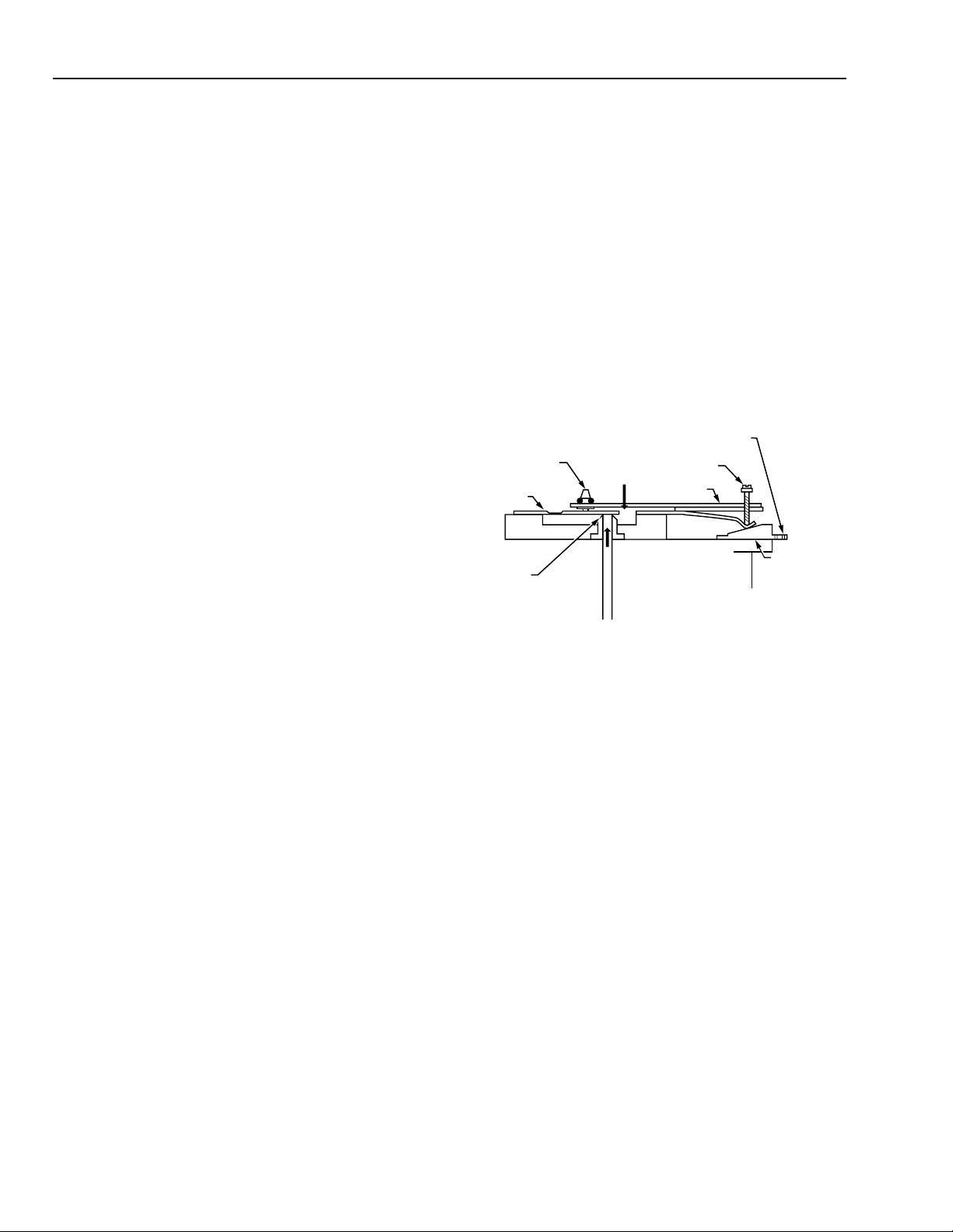
Flapper-Nozzle Operation
Flapper-nozzle operation is generally the same for all TP970
and TP9600 Thermostats. The Thermostat provides a
branchline air pressure that is a function of the ambient
temperature in the room or controlled space. As shown in
Figure 1, the force of the temperature-sensing bimetal acting
on one side of the flapper (Force A) is balanced by the
feedback force of the pilot pressure through the nozzle
acting on the other side of the flapper (Force B).
SETPOINT
THROTTLING RANGE
ADJUSTMENT
FORCE A
FLAPPER
NOZZLE
FORCE B
BIMETAL
IN BALANCED STATE,
FORCE B EQUALS FORCE A
Fig. 1. Flapper-Nozzle-Bimetal Assembly.
The position of the flapper over the nozzle changes and
creates a new pilot pressure when the bimetal force changes
(through temperature or setpoint change). This pilot pressure
feeds into the valve unit, which converts the low-capacity
pilot pressure to a high-capacity branchline change (see the
Valve Unit Operation section). Feedback at the nozzle
regulates the pressure to negate the effect of normal main
air supply fluctuations on the branch line.
Adjusting the throttling (proportioning) range changes the
flapper lever position. Moving the setpoint cam changes the
bimetal operating force and thus the setpoint.
KNOB
CALIBRATION
SCREW
SETPOINT
CAM
C6046
In force-balance design, two forces oppose each other until
they are equal, or balanced. The TP970 and TP9600 Series
Thermostats use the force of the bimetal to close the flapper
over the nozzle and the opposing force of the air pressure in
the nozzle chamber to lift the flapper (see the FlapperNozzle Operation section). When the forces are equal, a
force-balance condition exists.
The throttling range setting and the calibration reference
temperature determine the Thermostat span and calibration
point. At control point the nozzle-flapper-bimetal assembly
(acting through the calibration screw, setpoint cam, and the
77-9382—1
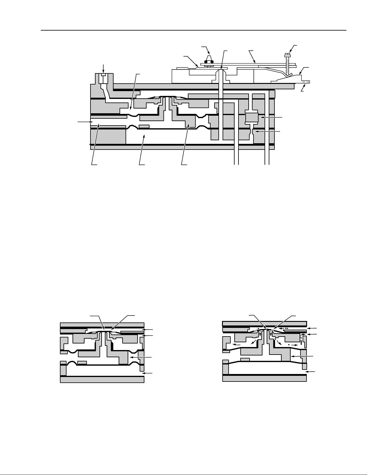
Valve Unit Operation
TP970, TP9600, TP971, TP9610, TP972, and TP9620
Thermostats use force-balance valve units to amplify airflow
and minimize air consumption without loss of required device
capacity. Figure 2 is a cross-section of a TP970 and TP9600
Thermostat showing the relationship of the valve unit to the
bimetal, nozzle, and other components.
2
TP790 AND TP9600 SERIES PNEUMATIC THERMOSTATS
POINT A
EXHAUST AIR
POINT B
MAIN LINE
BRANCH
LINE
PILOT AIR
C6049-1
NOTE: THE SEAL AT POINT A DOES NOT
ALLOW AIR TO EXHAUST.
VALVE
THROTTLING RANGE
ADJUSTMENT
FLAPPER
BLEED
BRANCHLINE
PRESSURE TAP
EXHAUST
BRANCHLINE
CHAMBER
PILOT
PILOT
CHAMBER
Fig. 2. Cross Section of TP970 and TP9600 Thermostat Showing Valve Unit and Airflow.
TP970, TP9600, TP971, TP9610, TP972, and TP9620
Thermostats are designed around a valve unit for flow
amplification rather than conventional pressure amplification.
Branchline chamber and pilot chamber design are such that
branch pressure is equal to nozzle pressure at a higher
capacity.
Figures 3, 4, and 5 are cross-sections of the valve unit only,
showing air passages and the pilot-branch diaphragm
relationship.
Figure 3 shows a valve unit in a strategic or balanced
condition. All the forces are equal; BLP equals the pilot-line
pressure.
No main air enters the branchline chamber and no exhaust
air leaves the branchline chamber. In this static condition,
the valve is sealed at both Points A and B, preventing airflow.
CALIBRATION
SCREW
SETPOINT
CAM
SETPOINT
KNOB
C6047-1
VALVE
NOZZLE
BRANCH LINE
BIMETAL
MAIN
LINE
FILTER
RESTRICTOR
Figure 4 shows the valve unit supplying air to the branch
line. This condition occurs when the bimetal sensing element
forces the Thermostat flapper to ward the nozzle, decreasing
the nozzle-flapper gap and increasing the pilot pressure.
The increased pilot pressure against the pilot diaphragm
overcomes the force of the BLP on the branchline
diaphragm. This change opens the valve unit at Point B,
allowing main air to flow into the branch line. BLP builds until
the pressure against the branch diaphragm again equals the
pressure against the pilot chamber diaphragm. The main
airflow then shuts off, bringing the valve unit into a balanced
condition at a new pressure.
With direct-acting bimetal sensors, a temperature increase
closes the nozzle-flapper gap; with reverse-acting bimetal
sensors, a temperature increase opens the nozzle-flapper
gap. The arrows in the air passages in Figure 4 show the
direction of airflow.
EXHAUST
POINT A
BRANCH
PILOT CHAMBER
POINT B
MAIN LINE
BRANCH
CHAMBER
VALVE
PILOT AIR
Fig. 3. Valve Unit Flow Amplifier in a
Balanced (Static) Condition.
LINE
C6048-1
Fig. 4. Valve Unit Shown with Pilot
Chamber Pressure Increased.
3
77-9382—1

TP970 AND TP9600 SERIES PNEUMATIC THERMOSTATS
Figure 5 shows the valve unit bleeding down the BLP. This
condition occurs when the bimetal sensing element relaxes
its force against the flapper, allowing the nozzle-flapper gap
to increase.
POINT A
VALVE
PISTON
EXHAUST
AIR
NOTE: THE SEAL AT POINT A DOES NOT
ALLOW AIR TO EXHAUST.
Fig. 5. Valve Unit Shown with Pilot
Chamber Pressure Decrease.
The reduction in pilot pressure against the pilot diaphragm
allows the BLP to overcome the pressure in the pilot
chamber. This change moves the valve piston down, sealing
off Point B and opening Point A. Branchline air bleeds off
until the pressure against the branchline diaphragm equals
the pressure against the pilot chamber diaphragm. When the
pressures become equal, the exhaust air is shut off at Point
A. The valve unit is again in a balanced condition at the new
pressure. The arrows in the air passages in Figure 5 show
the direction of airflow.
The preceding explanation of valve unit operation is very
important to understanding TP970, TP9600, TP971, TP9610,
TP972, and TP9620 operation. As can be seen from Figures
3, 4, and 5, pilot pressure changes affect BLP changes in
the same ratio. There is no pressure gain to amplify errors as
with other pneumatic Thermostats. Still, the main air supply
being switched through the valve unit, provides fast, high
capacity increase and decrease of BLP.
POINT B
MAIN LINE
BRANCH
LINE
VALVE
PILOT AIR
C6050-1
THROTTLING
RANGE
ADJUSTMENT
FLAPPER
BIMETAL
NOZZLE
AIR CONNECTION
FILTER AND
RESTRICTOR
SETPOINT
KNOB
CALIBRATION
SCREW
SETPOINT
CAM
SETPOINT
KNOB
C6051
Fig. 6. Basic TP973 and TP9630 Thermostat.
The TP973 and TP9630 are used on one- or two-pipe
systems. Connections are made to main and branch for twopipe applications (see Fig. 7). The main air connector is
plugged when used on one-pipe applications (Fig. 8). This
causes the Thermostat to operate like any other bleed-type
thermostat with a remote restrictor.
SETPOINT
KNOB
CALIBRATION
SCREW
FLAPPER
THROTTLING RANGE
ADJUSTMENT
BIMETAL
TP973A, B AND TP9630 A, B LOW CAPACITY, SINGLE-TEMPERATURE
THERMOSTA TS
General
The TP973A, B TP9630A, B (Fig. 6) are the simplest
Thermostats in the TP970 and TP9600 Series. Ever y other
model includes the basic TP973 and TP9630 assembly with
additions. Air going to the controlled device from the TP973
and TP9630 passes through an internal restrictor. The
TP973A and TP9630A are direct acting (signal pressure
increases as the temperature increases); the TP973B,
reverse acting (signal pressure increases as the temperature
decreases).
77-9382—1
NOZZLE
NOZZLE
CHAMBER
RESTRICTOR
MAIN LINE
CAM
SLOPE
BRANCH
LINE
BACKPLATE
TO CONTROLLED
DEVICE
SETPOINT
CAM
C6052
Fig. 7. TP973 and TP9630 Operating Section.
4
 Loading...