

Honeywell ToxyPoint User Manual

Dispositif de détection de gaz
Gas Detection Device
Manuel de l’utilisateur
ToxyPoint
User Manual
ERP 511407
6/07


Gas Detection Device
ToxyPoint
User Manual
ERP 511407
6/07


Notices and Trademarks
Copyright by Honeywell International Inc.
Release 511407 February 2007
While this information is presented in good faith and believed to be accurate,
Honeywell disclaims the implied warranties of merchantability for a particular
purpose and makes no express warranties except as may be stated in its
written agreement with and for its customers.
In no event is Honeywell liable to anyone for any indirect, special or
consequential damages. The information and specifications in this document
are subject to change without notice.
Honeywell Analytics
4005 Matte Blvd, Unit G
Brossard, Quebec, J4Y 2P4
511407 ToxyPoint User Manual iii
6/07 Honeywell


Contacts
World Wide Web
The following Honeywell Websites may be of interest to our customers:
Honeywell Organization WWW Address (URL)
Honeywell Analytics http://www.honeywellanalytics.com
Corporate http://www.honeywell.com
International http://content.honeywell.com/global/
Telephone
Contact us by telephone at the numbers listed below:
Organization Phone Number
United States
and Canada
Asia Pacific
Europe
Latin America
Honeywell Analytics
Honeywell Asia Pacific Inc.
Hong Kong
Honeywell Pace
Brussels, Belgium
Honeywell International Inc.
Sunrise, Florida, U.S.A.
1-800-563-2967
1-450-619-2450
Fax: 1-888-967-9938
(852) 23 31 9133
[32-2]728-2711
(954) 845-2600
Sales Informations
Contact us at sales@vulcaininc.com
511407 ToxyPoint User Manual v
6/07 Honeywell

Symbol Definitions
The following table lists the symbols used in this document to denote
certain conditions:
Symbol Definition
ATT ENTION: Identifies information that requires
special consideration
TIP: Identifies advice or hints for the user, often
in terms of performing a task
REFERENCE _ INTERNAL: Identifies an
additional source of information within the
bookset.
Indicates a situation which, if not avoided, may
CAUTION
result in equipment or work (data) on the system
being damaged or lost, or may result in the
inability to properly operate the process.
CAUTION: Indicates a potentially hazardous
situation which, if not avoided, may result in minor
or moderate injury. It may also be used to alert
against unsafe practices.
CAUTION: Symbol on the equipment refers the
user to the product manual for additional
information. The symbol appears next to required
information in the manual.
WARNING: Indicates a potentially hazardous
situation which, if not avoided, could result in
serious injury or death.
WARNING symbol on the equipment refers the
user to the product manual for additional
information. The symbol appears next to required
information in the manual.
511407 ToxyPoint User Manual vii
6/07 Honeywell


Contents
INTRODUCTION ............................................................11
Safety Information - Read First ......................................................... 11
Elements Drawing ................................................................................. 12
Sensor Installation Locations ............................................................ 13
Mounting the Enclosure ..................................................................... 14
System Design Specifications ........................................................... 15
Cable Installation ............................................................................... 16
System Wiring Diagram ..................................................................... 17
4-20 mA Loop Installation .................................................................. 18
Connect the Transmitter ........................................................................ 18
Alarm Output(s) ..................................................................................... 18
Connect the Controller and Power Supply ............................................ 18
OPERATION ...................................................................19
Sensor Startup Cycle ........................................................................ 19
Power-up ............................................................................................... 19
Test ToxyPoint Calibration .................................................................... 19
Instrument Status Advice ...................................................................... 20
Alarm Output Setpoints ......................................................................... 20
Automatic Self-Test ............................................................................... 20
Self-Test Fail ......................................................................................... 21
Operational Life ..................................................................................... 21
Life-Ended Warning ............................................................................... 21
Life-Ended Alarm ................................................................................... 21
Care ................................................................................................... 21
SPECIFICATIONS ..........................................................22
Safety Specifications ............................................................................. 22
General Specifications .......................................................................... 22
LIMITED WARRANTY ...................................................25
Limited Warranty ................................................................................... 25
ReStocking Policy ................................................................................. 25
Exclusions ............................................................................................. 26
Warranty Limitation and Exclusion ........................................................ 26
Disclaimer of Unstated Warranties ........................................................ 27
Limitation of Liability .............................................................................. 27
511407 ToxyPoint User Manual ix
6/07 Honeywell


Introduction
Safety Information
Introduction
The ToxyPoint gas monitor provides continuous monitoring for carbon
monoxide (CO) hazards in ambient air. The monitor is a 2-wire, 4-20mA
transmitter with sensor. It is factory calibrated and tested and has a
maximum operating life of 3 years.
Safety Information
Users of the ToxyPoint require a full understanding of the installation,
operating and maintenance instructions, otherwise protection provided
by the monitor may be impaired. Read the following Warnings before
using the monitor.
• Install according to local electrical regulations and codes.
• Installation should be performed by qualified personnel.
• Do not paint over the sensor screen.
• Do not activate the monitor after the date on the package.
• Make sure the sensor screen is free of dirt and debris.
• Make sure the sensor screen is not covered.
• Do not expose the monitor to electrical shock and/or continuous
mechanical shock.
• Do not expose the sensor to high pressure water spray.
• Do not use the monitor if it is damaged. Before use inspect the
monitor. Look for cracks, missing metals or plastics. If the monitor is
damaged, contact Vulcain immediately.
• The warranty will be voided if the customer or any unauthorized
service personnel attempts to repair the unit.
• The ToxyPoint should be interfaced to a Class 2 or Limited circuit.
A limited circuit is a circuit supplied by sources such as a battery or a
transformer winding where the open-circuit potential is not more than 30
V r.m.s or 42.4 V.d.c., and the energy available to the circuit is limited
according to one of the following:
The current under any condition of load, including short circuit, is not
more than 8A measured after 1 minute of operation;
The source is RATED or set to limit its power output to 150 VA under any
condition of load including short circuit;
An overload protector or circuit component opens to interrupt the power
output at a lower value than 150 VA under any condition of load including
short circuit.
511407 ToxyPoint User Manual 11
6/07 Honeywell
Introduction
2
1
3
4
6
7
8
5
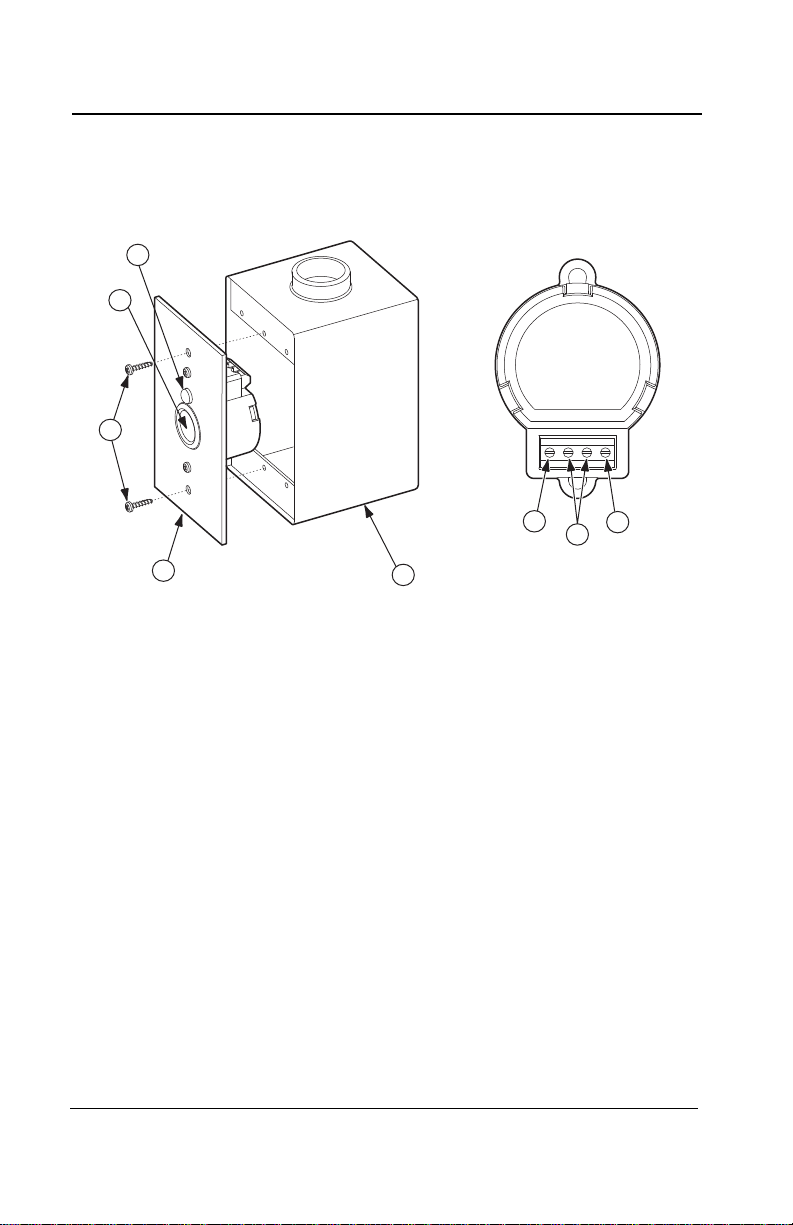
Elements Drawing
Elements Drawing
1. LED indicator
2. Sensor with sensor screen
3. Mounting screws (not included)
4. Mounting/cover plate
5. Standard single outlet (gang1) electrical box (not included)
6. O/P2 High alarm output Two
7. Sensor wiring terminals; 4-20 mA and 24 Vdc
8. O/P1 Low alarm output One
12 ToxyPoint User Manual 511407
Honeywell 6/07

Introduction
Sensor Installation Locations
Sensor Installation Locations
The following suggestions should be considered to assure detection of
the target gas. Select the most suitable location for each sensor.
Air Currents: If there are fans, wind, or other sources of air
movement, gases may tend to rise or collect in
certain areas of a facility. The local air currents
should be assessed to aid in selecting the sensor
location. Air convection can often be more important
in determining gas concentration areas than factors
of Vapor Density.
Gas Emission As a rule, at least one sensor should be located in
Sources: close proximity to each point where an emission is
likely to occur.
Height: We suggest, dependent of air currents, that the
ToxyPoint be installed at approximately 3 to 5 feet
above ground or higher where CO emission is likely
to accumulate.
511407 ToxyPoint User Manual 13
6/07 Honeywell
Introduction
1.07 m
3.5’
8.26 cm
3 ¼”
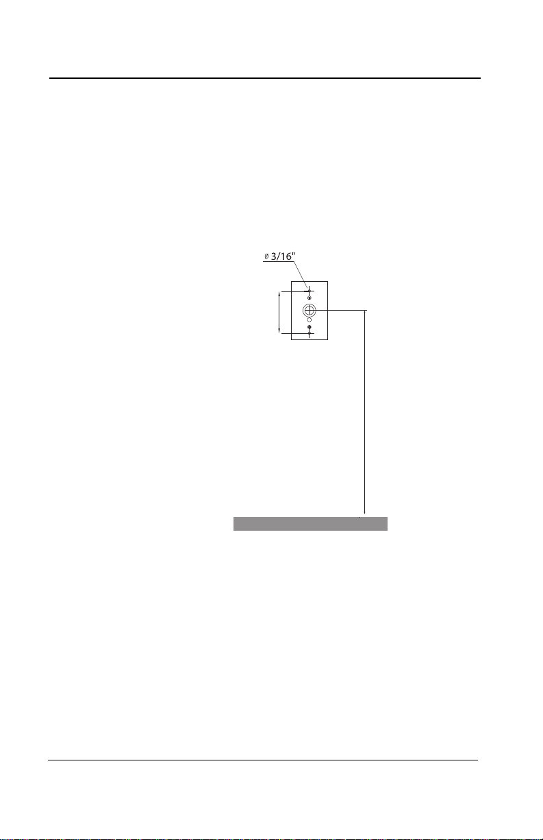
Mounting the Enclosure
Mounting the Enclosure
ToxyPoint is mounted in a standard single outlet (gang1) electrical box
supplied by the customer. The ToxyPoint Mounting Plate fits boxes
mounted in drywall (new construction) or is surface mounted.
The diagram below provides installation and mounting heights.
14 ToxyPoint User Manual 511407
Honeywell 6/07

Introduction
Mounting the Enclosure
Recommended Installation Heights
Relative
Gas Detected
CO Carbon monoxide 0.968 3-5 feet (1 - 1.5m) from floor
The installation heights recommended by Honeywell represent
general guidelines. Always confirm local laws and regulations
before proceeding, as these take precedence over
manufacturer’s recommendations.
Density
(air = 1)
Height
511407 ToxyPoint User Manual 15
6/07 Honeywell

Introduction
Cable Installation
Cable Installation
The distance the 4-20 mA signal can travel is dependent on several
factors including cable gauge. Maximum cable resistance is 650 ohms
less the controller resistance.
The table below assumes a constant 24 volt power supply (at 20C),
copper wire and a Controller resistance of 250 ohms. The signal range
from the Controller/PLC etc. to the ToxyPoint takes into account the
return loop. The distance shown is from the Controller to the
Transmitter.
Maximum Cable Lengths Between Controller and ToxyPoint
Conductor size Distance
22 AWG 0.64 mm 2,045 m (6,715 ft)
20 AWG 0.75 mm 3,253 m (10,953 ft)
18 AWG 1.00 mm 5,167 m (16,953 ft)
Recommended: Use shielded cable, or cable in conduit to
avoid electrical interference. The shield (including mylar)
must be grounded. Keeping the shield as short as possible,
tie the shield and extra wires to the electrical box grounding
screw. Pull 2-wire cable into the enclosure(s).
Output Signals: If accessing the output signal(s) at O/P1
and/or O/P2 additional wire(s) will be required from the
sensor. Wire as shown in the Alarm Outpus Installation
diagram.
16 ToxyPoint User Manual 511407
Honeywell 6/07
 Loading...