

Page 1
Operating Manual
Touchpoint Pro
Page 2

REVISIONS
Touchpoint Pro
Pt. No. 2400M2566_6_EN ii Operating Manual
Revision History
Revision
Comment
Date
Issue 1
A04815
Nov 2016
Issue 2
A04939
Jan 2017
Issue 3
A05034
Oct 2017
Issue 4
A05082
Mar 2018
Issue 5
A05241
Apr 2019
Issue 6
A05304
July 2019
Page 3

LEGAL NOTICES
Touchpoint Pro
Pt. No. 2400M2566_6_EN iii Operating Manual
Disclaimer
In no event shall Honeywell be liable for any damages or injury of any nature or kind, no matter how caused, that arise from
the use of the equipment referred to in this manual.
Strict compliance with the safety procedures set out and referred to in this manual, and extreme care in the use of the
equipment, are essential to avoid or minimise the chance of personal injury or damage to the equipment.
The information, figures, illustrations, tables, specifications, and schematics contained in this manual are believed to be
correct and accurate as at the date of publication or revision. However, no representation or warranty with respect to such
correctness or accuracy is given or implied and Honeywell will not, under any circumstances, be liable to any person or
corporation for any loss or damages incurred in connection with the use of this manual.
The information, figures, illustrations, tables, specifications, and schematics contained in this manual are subject to change
without notice.
Unauthorised modifications to the gas detection system or its installation are not permitted, as these may give rise to
unacceptable health and safety hazards.
By installing this equipment on a computer network, the owner accepts full and unequivocal responsibility for ensuring that it
is protected against all cyber threats and illegal tampering during the lifetime of the equipment.
Any software forming part of this equipment should be used only for the purposes for which Honeywell supplied it. The user
shall undertake no changes, modifications, conversions, translations into another computer language, or copies (except for a
necessary backup copy).
In no event shall Honeywell be liable for any equipment malfunction or damages whatsoever, including (without limitation)
incidental, direct, indirect, special, and consequential damages, damages for loss of business profits, business interruption,
loss of business information, or other pecuniary loss, resulting from any violation of the above prohibitions.
Warranty
Honeywell Analytics warrants the Touchpoint Pro system against defective parts and workmanship, and will repair or (at its
discretion) replace any components that are or may become defective under proper usage within 12 months from the date of
commissioning by a Honeywell Analytics approved representative* or 18 months from shipment from Honeywell Analytics,
whichever is sooner.
This warranty does not cover consumables, batteries, fuses, normal wear and tear, or damage caused by accident, abuse,
improper installation, unauthorized use, modification or repair, ambient environment, poisons, contaminants or abnormal
operating conditions.
This warranty does not apply to sensors or components that are covered under separate warranties, or to any 3rd-party
cables and components.
Any claim under the Honeywell Analytics Product Warranty must be made within the warranty period and as soon as
reasonably practicable after a defect is discovered. Please contact your local Honeywell Analytics Service representative to
register your claim.
This is a summary. For full warranty terms Refer to the Honeywell Analytics’ General Statement of Limited Product
Warranty, which is available on request.
* A Honeywell Analytics approved representative is a qualified person trained or employed by Honeywell Analytics, or a
qualified person trained in accordance with this manual.
Copyright Notice
Microsoft, MS and Windows are registered trademarks of Microsoft Corp.
Other brand and product names mentioned in this manual may be trademarks or registered trademarks of their respective
companies and are the sole property of their respective holders.
Honeywell is the registered trademark of Honeywell Safety and Productivity Solutions (SPS).
Find out more at www.honeywellanalytics.com
Page 4

LEGAL NOTICES
Touchpoint Pro
Pt. No. 2400M2566_6_EN iv Operating Manual
This page is deliberately blank.
Page 5

CONTENTS
Touchpoint Pro
Pt. No. 2400M2566_6_EN v Operating Manual
Contents
1 Important Safety Information ......................................................................................................... 1
1.1 International Standards ....................................................................................................... 1
1.2 Warnings ............................................................................................................................. 2
1.3 Cautions .............................................................................................................................. 3
1.3.1 Intended Readers .......................................................................................................... 3
1.3.2 Conventions Used ......................................................................................................... 3
1.3.3 TPPR Documentation Suite ........................................................................................... 4
1.3.4 Document Translations .................................................................................................. 4
1.3.5 Associated Documents ................................ .................................................................. 4
1.3.6 How to Use this Document ............................................................................................ 4
1.3.7 Further Information and Help ......................................................................................... 4
2 Safety Hazards, Warnings and Cautions ....................................................................................... 5
2.1 Safety .................................................................................................................................. 5
2.1.1 Warnings and Cautions ................................................................................................. 5
2.1.2 Safety Hazards .............................................................................................................. 6
2.2 Location and Description of Warning Labels ....................................................................... 8
2.2.1 Safety Warning Labels ................................................................................................... 8
2.2.2 Equipment Rating Labels (Hazardous Locations) .......................................................... 9
2.2.3 Warning Labels ............................................................................................................ 10
3 Touchpoint Pro Introduction ........................................................................................................ 11
3.1 TPPR Access Levels ........................................................................................................ 11
3.2 TPPR Control System Layout ........................................................................................... 12
3.2.1 Centralised Command and Control Option .................................................................. 13
3.2.2 Distributed Command and Control (Remote Units) Option .......................................... 13
3.3 TPPR System Key Components ....................................................................................... 14
3.3.1 Enclosures and Racks ................................................................................................. 14
3.3.2 TPPR Controller User Interfaces ................................................................................. 14
3.3.3 SD Card ....................................................................................................................... 15
3.3.4 USB Port ...................................................................................................................... 15
3.3.5 PC Configuration Software .......................................................................................... 15
3.3.6 PC Operating Systems ................................................................................................ 15
3.3.7 Webserver Software .................................................................................................... 15
3.3.8 Licences....................................................................................................................... 16
3.3.9 TPPR Controller Hardware .......................................................................................... 16
3.3.10 TPPR Backplane ......................................................................................................... 17
3.3.11 Ring Network ............................................................................................................... 17
3.3.12 TPPR Modules ............................................................................................................. 19
3.3.13 Sensor Catalogue ........................................................................................................ 19
3.4 Power Supply Options ...................................................................................................... 20
3.4.1 Power Supply Unit Modules (PSU) .............................................................................. 20
3.4.2 Power Redundancy Module (RDN) .............................................................................. 21
Page 6

CONTENTS
Touchpoint Pro
Pt. No. 2400M2566_6_EN vi Operating Manual
3.4.3 DC Uninterruptible Power Supply (DC-UPS) Module .................................................. 22
3.4.4 Backup Batteries .......................................................................................................... 23
4 Configuration Files........................................................................................................................ 25
4.1 Viewing and Editing the Configuration .............................................................................. 25
4.1.1 To View or Edit the Configuration ................................................................................ 25
4.2 To Back Up the Configuration ........................................................................................... 26
4.3 Restoring the Configuration .............................................................................................. 26
4.4 Deleting the Configuration ................................................................................................ 26
5 Normal Day-to-Day Operation ...................................................................................................... 27
5.1 TPPR Controller Touchscreen Interface ........................................................................... 27
5.2 TPPR PC Configuration Software Interface ...................................................................... 27
5.3 TPPR Webserver Interface ............................................................................................... 27
5.4 TPPR Safety Function ...................................................................................................... 28
5.5 Touchscreen Operation .................................................................................................... 28
5.5.1 System Status Screen Alert Icons ............................................................................... 28
5.5.2 Active Event History ..................................................................................................... 29
5.5.3 Touchscreen Layout .................................................................................................... 29
5.5.4 Touchscreen Navigation .............................................................................................. 30
5.5.5 Login Requirements ..................................................................................................... 32
5.6 How to Recalibrate the Touchscreen ................................................................................ 32
5.7 How to View Input Channels and Input Details ................................................................. 32
5.8 How to View Output Channels .......................................................................................... 33
5.9 How to View the Trend Graph ................................ ........................................................... 34
5.9.1 To View the Trend Graph............................................................................................. 34
5.10 How to View Event History ................................................................................................ 35
5.11 How to View Event Reports .............................................................................................. 35
5.11.1 How to Generate Reports ............................................................................................ 35
5.11.2 How to Print Active Events........................................................................................... 35
5.12 How to Access Diagnostic information .............................................................................. 36
5.13 Managing the Integral SD Card......................................................................................... 36
5.13.1 SD Card Purposes ....................................................................................................... 36
5.13.2 SD Card Management ................................................................................................. 37
5.13.3 SD Capacity Reporting ................................................................................................ 37
5.13.4 How to Check the SD Card Capacity ........................................................................... 37
5.13.5 Ejecting the SD Card ................................................................................................... 37
5.13.6 Replacing an SD Card ................................................................................................. 37
5.14 Accessing Help ................................................................................................................. 37
5.15 System State Relays ......................................................................................................... 38
5.15.1 ROM Output Relays on System Fail ................................................................ ............ 38
6 Alarms, Faults, Warnings and Inhibits ........................................................................................ 39
6.1 Latching Alarms ................................................................................................................ 39
6.2 STEL / LTEL Alarms ......................................................................................................... 39
Page 7

CONTENTS
Touchpoint Pro
Pt. No. 2400M2566_6_EN vii Operating Manual
6.2.1 Using the STEL Alarm ................................................................................................. 39
6.2.2 Assigning the STEL Alarm to an Output Relay ............................................................ 40
6.3 Rate Alarm ........................................................................................................................ 40
6.4 Relay Activated Outputs ................................................................................................... 40
6.5 Sensor Over Range Operation.......................................................................................... 40
6.5.1 Gas Readings .............................................................................................................. 41
6.6 Catalytic Sensor Over Range Operation ........................................................................... 41
6.7 Full Scale Exceeded and Over Range Warning Operation ............................................... 41
6.7.1 Event Status with a Rising Gas Reading ..................................................................... 42
6.7.2 Event Status as the Gas Concentration Decreases ..................................................... 42
6.7.3 Special Considerations when using Catalytic Sensors ................................................ 43
6.7.4 Configuration of Relay Outputs .................................................................................... 43
6.8 Responding to Alarms, Faults and Warnings .................................................................... 44
6.8.1 To View Active Alarms ................................................................................................. 45
6.8.2 To Acknowledge an Active Alarm ................................................................................ 45
6.8.3 To Reset a Latched Alarm ........................................................................................... 46
6.9 Viewing Faults and Warnings............................................................................................ 46
6.9.1 To View Faults and Warnings ...................................................................................... 46
6.9.2 To Acknowledge (Accept) a Fault or Warning.............................................................. 47
6.9.3 To Reset a Latched Fault or Warning .......................................................................... 47
6.10 Inhibiting a Channel .......................................................................................................... 47
6.10.1 How to Inhibit a Channel .............................................................................................. 47
6.10.2 Channel Auto-Inhibits .................................................................................................. 48
7 Maintenance Procedures .............................................................................................................. 49
7.1 Routine Maintenance ........................................................................................................ 49
7.2 Periodic Maintenance ....................................................................................................... 50
7.2.1 Battery Enclosure Maintenance ................................................................................... 50
7.2.2 Cable Maintenance ...................................................................................................... 50
8 How to Test the TPPR System ..................................................................................................... 51
8.1 Introduction ....................................................................................................................... 51
8.2 LED Panel Test ................................................................................................ ................. 52
8.3 Field Inputs Test ............................................................................................................... 52
8.4 Configuration Settings Test ............................................................................................... 53
8.4.1 How to use the Configuration Settings Test Mode ....................................................... 53
8.5 Cause and Effect Test ...................................................................................................... 54
8.5.1 How to use the Cause and Effect Test Mode:.............................................................. 54
8.6 Analog Output Test ........................................................................................................... 55
8.7 Panel Button Test ............................................................................................................. 55
8.8 System Relay Test ............................................................................................................ 56
8.9 LCD Screen Test .............................................................................................................. 57
8.10 How to Exercise the Output Relays .................................................................................. 57
9 Calibrating Gas Sensors ............................................................................................................... 58
Page 8

CONTENTS
Touchpoint Pro
Pt. No. 2400M2566_6_EN viii Operating Manual
9.1.1 Calibration Definitions .................................................................................................. 58
9.2 Calibrating AIM-mV Input Channels .................................................................................. 59
9.3 Calibrating AIM-mA Input Channel Loops ......................................................................... 59
10 System Troubleshooting .............................................................................................................. 61
10.1 Observed Problem ............................................................................................................ 61
10.2 Other Issues...................................................................................................................... 65
10.2.1 Modules Reporting a Fault ........................................................................................... 65
11 Error Codes ................................................................................................................................... 66
12 Other Potential Issues .................................................................................................................. 77
12.1 Batteries Fail to Come Online ........................................................................................... 77
12.2 DC-UPS Shows that Batteries are Failing ......................................................................... 77
12.3 Module Faults ................................................................................................................... 77
12.4 Modules Reporting a Fault ................................................................................................ 77
12.5 Spurious Fault Reporting .................................................................................................. 78
13 Further Assistance and Training ................................................................................................. 79
14 EU Declaration of Conformity ...................................................................................................... 80
14.1 Applicable National and International Standards .............................................................. 80
14.2 National and International Certificates for Zone 2 Div. 2 ................................................... 81
14.3 European Performance Approval (DEKRA Exam) for Systems ........................................ 82
14.3.1 Approved Components ................................................................................................ 82
14.3.2 Special Conditions for Use When Used for Explosion Protection ................................ 83
14.3.3 Special Conditions for Use When Used for Measurement of Toxic Gases or Oxygen . 83
14.3.4 Configuration of Relay Outputs for safety-related switching operations ....................... 84
14.3.5 Compliance with EN 45544-2 (Toxic Gases) ............................................................... 84
14.3.6 Compliance with EN 50104 (Oxygen) .......................................................................... 84
14.4 Important Notes on Certification........................................................................................ 84
15 Ordering Information .................................................................................................................... 85
15.1 TPPR System ID Configuration......................................................................................... 85
15.2 TPPR Components Part Numbers .................................................................................... 86
16 Disposal of Redundant / Unserviceable Parts ............................................................................ 87
16.1 Restriction of Hazardous Substances (RoHS) Directive ................................................... 87
16.2 Waste Electrical and Electronic Equipment (WEEE) Directive ................................ .......... 87
16.3 TPPR System Construction .............................................................................................. 87
16.3.1 TPPR Safe Area Enclosures: ....................................................................................... 87
16.3.2 TPPR Battery Enclosure .............................................................................................. 87
16.3.3 TPPR 19 Inch Rack ..................................................................................................... 87
16.3.4 TPPR I/O Modules ....................................................................................................... 87
16.3.5 TPPR Power Supply Units ........................................................................................... 88
16.3.6 TPPR Ring Coupling Module ....................................................................................... 88
16.3.7 TPPR Backplanes ........................................................................................................ 88
16.3.8 TPPR Packaging ......................................................................................................... 88
17 Table of Icons ................................................................................................................................ 89
Page 9

CONTENTS
Touchpoint Pro
Pt. No. 2400M2566_6_EN ix Operating Manual
18 List of Illustrations ................................................................ ........................................................ 91
19 List of Tables ................................................................................................................................. 93
Page 10
SAFETY
Touchpoint Pro
Pt. No. 2400M2566_6_EN 1 Operating Manual
1 Important Safety Information
The Equipment referred to in this manual contains components and assemblies that are each certified for use in a variety of
differing environments, and it is the site owner’s responsibility to confirm the suitability of the equipment and any associated
computer networks prior to its installation and use.
The Equipment assemblies referred to in this manual are collectively certified for use in a gas detection system only. Any
other use is not currently certified and is not authorised by the manufacturer.
For installation in Canada and the USA, for both ordinary and hazardous locations, all connections, cabling, overcurrent
protection and installations must strictly adhere to both the National Electrical Code (NEC) and the Canadian Electrical Code
(CEC).
Check the product rating plate and look for the following marks to ensure that the supplied equipment is suitable for its
intended location and purpose:
Products bearing the CE mark conform to all applicable European Directives as stated on the Honeywell product specific EU
Declaration of Conformity.
Products bearing the CSA mark conform to the requirements for Ordinary Locations, and where marked on components and
apparatus, Zone 2 and Division 2 Hazardous Locations.
Products, components and apparatus bearing the ATEX Explosion Protection mark conform to the requirements for Zone 2
Potentially Explosive Atmospheres.
1.1 International Standards
All personnel should acquaint themselves with the contents of the following standards before commencing work on gas
detection systems:
IEC 60079-29-2, which gives guidance on, and recommended practice for, the selection, installation, safe use and
maintenance of electrically operated group II apparatus intended for use in industrial and commercial safety applications for
the detection and measurement of flammable gases complying with the requirements of EN 60079-29-1.
IEC 60079-20-1, which gives guidance on material characteristics for gas and vapour classification; test methods and data.
It also explains how to convert test and calibration gas (span gas) concentrations from %LFL to %v/v.
EN 45544-4, which gives guidance on electrical apparatus used for the direct detection and direct concentration
measurement of toxic gases and vapours and a guide for their selection, installation, use and maintenance.
WARNING
FOR SAFETY REASONS THIS EQUIPMENT MUST BE OPERATED BY QUALIFIED PERSONNEL ONLY. READ
AND UNDERSTAND THE INSTRUCTION MANUAL COMPLETELY BEFORE OPERATING OR SERVICING THE
EQUIPMENT.
ATTENTION
POUR DES RAISONS DE SÉCURITÉ, CET ÉQUIPEMENT DOIT ÊTRE UTILISÉ, ENTRETENU ET RÉPARÉ
UNIQUEMENT PAR UN PERSONNEL QUALIFIÉ. ÉTUDIER LE MANUEL D’INSTRUCTIONS EN ENTIER AVANT
D’UTILISER, D’ENTRETENIR OU DE RÉPARER L’ÉQUIPEMENT.
Page 11

SAFETY
Touchpoint Pro
Pt. No. 2400M2566_6_EN 2 Operating Manual
1.2 Warnings
Read the following Warnings and Cautions before starting any work on the TPPR system.
WARNINGS
1. For safety reasons this equipment must be operated by qualified personnel only. Read and understand the
Instruction Manual completely before operating or servicing the equipment.
2. The equipment specified in this manual is only to be installed by the Manufacturer’s trained personnel, or by
competent persons trained in accordance with the Manufacturer’s installation instructions.
3. Installation must be in accordance with the recognized standards of the appropriate authority in the country
concerned. Refer to local, national and company regulations.
4. To protect against cyber threats, installation on a computer network must be carried out in collaboration with
your Company’s IT department or professional IT consultants, and the guidelines and recommendations in the
Honeywell Network Security Guide should be followed.
5. Do not operate the Touchpoint Pro system or its components outside of their rated operating specification.
6. Touchpoint Pro must not be operated in Oxygen enriched atmospheres, i.e. greater than 25% v/v Oxygen.
7. All equipment containing a User Interface must be suitably protected from direct sunlight and rain.
8. Power Supply Fluctuations are not to exceed DC 18 – 32 V SELV Supply or ±10 % of nominal.
9. All versions of Enclosure are electrical Class 1, and must be connected to Protective Earth (Ground).
10. The Touchpoint Pro installation must include a means of isolating or disconnecting the input voltage supply.
The isolation or disconnection device must be conveniently located close to the system and be clearly labelled.
For an AC mains voltage supply, the isolation or disconnection device must disconnect both the line and neutral
poles, but maintain earth (ground) continuity.
11. The Touchpoint Pro input voltage supply must include over-current protection.
12. All cabling must be appropriately rated and approved in accordance with local, national and company
regulations, and suitable for the installation. Additionally, cabling must satisfy requirements defined in the
manuals of connected field devices, in particular if the field device is certified for use in a hazardous location.
13. All signal cables and interconnections must be shielded and the shields terminated only at the unified earth
(ground) bus bar situated inside the enclosure.
14. All conduits and cable armour shall be bonded to protective earth (ground). To avoid ground loops, isolating
cable entry glands shall be used at the enclosure end where conduits or armour are earthed at the sensor end.
15. Cable entry glands, blanking plugs, reducers, adaptors and breather devices must be suitably approved and
must not reduce the IP rating or protection levels. Items should not be used if there is a high risk of mechanical
damage to the equipment or enclosure.
16. Cable gland plates or blanking plates must be installed using the supplied gaskets and metal fixings. Failing to
do so will invalidate the IP rating.
17. Access doors and entry points must not be opened when a flammable gas atmosphere is present (Class 1
Div.2, Class 1 Zone 2, and Zone 2 [ATEX]).
18. Access doors and entry points must be kept closed when the system is energised in normal operation.
19. All equipment in this manual is rated to +2000 m (6562 ft.) altitude maximum.
20. Touchpoint Pro systems may contain hazardous live terminals. Appropriate precautions should be taken during
operation, installation, and maintenance and servicing. Specifically, operators must have appropriate training
and experience to be aware of the hazards to which they may be exposed, and of measures to minimise risk to
themselves or other people.
21. The protection provided by the equipment may be impaired if the equipment is used in a manner not specified
or authorised by the manufacturer. This includes being connected to an insecure TCP/IP network.
22. Be aware that extended exposure of a sensor element to certain concentrations of combustible gases and air
can introduce stress to the element that may seriously affect its performance, and therefore recalibration should
be carried out or the sensor replaced, or both, after an alarm due to an indication of a high concentration.
23. Risk Assessments should be carried out and alternative safety arrangements should be put in place BEFORE
beginning any servicing or maintenance.
Page 12
SAFETY
Touchpoint Pro
Pt. No. 2400M2566_6_EN 3 Operating Manual
1.3 Cautions
1.3.1 Intended Readers
This Manual should be read by everyone who operates or monitors the TPPR gas detection system. In addition this manual
may be used to train people who operate or monitor the TPPR gas detection system.
Only personnel who have been fully trained by Honeywell are authorised to Install, Set-up, Commission, Service, Test,
Repair, or Recondition Honeywell gas detection systems.
1.3.2 Conventions Used
The following conventions are used in this manual:
• ‘TPPR’ refers to the Touchpoint Pro Gas Detection System.
• ‘Start up’ refers to the action of switching on the system ready for use.
• ‘Power Cycle’ refers to cycling the power off and then on again.
• ‘Boot up’ refers to the action of starting the software from cold.
• ‘Reboot’ refers to shutting down and restarting the software without interrupting the power supply.
CAUTIONS
1. The USB Device port is for Maintenance use only. End users shall use only the USB Host port with a USB
Flash drive, and backup / restore / upgrades shall only be performed with the system in a safe (i.e. inhibited)
mode.
2. Touchpoint Pro power supply units, Ring Coupling Modules and Input / Output Modules have no user
serviceable parts. In the unlikely event of a failure, the power supply unit or module must be replaced using only
manufacturer supplied parts.
3. Do not use sharp objects to operate the Touchscreen as this could irreparably damage the User Interface and
adversely affect its IP rating.
4. Use only soft, damp cloths or screen wipes to clean the Touchpoint Pro. Do not use solvents or abrasives as
they will damage the User Interface.
5. Once commissioned, Touchpoint Pro is intended for continuous operation.
IMPORTANT
Personnel, who work on, or in the area of, the Touchpoint Pro Gas detection system must be made aware of
Chapter 2 – Safety Hazards, Warnings and Cautions.
Before unpacking the system, please read the documentation that accompanies it.
Page 13

SAFETY
Touchpoint Pro
Pt. No. 2400M2566_6_EN 4 Operating Manual
1.3.3 TPPR Documentation Suite
The TPPR documentation is supplied on CD-ROM with new systems, and is available to download from the Honeywell
Analytics website, whose address is on the back cover.
The downloadable TPPR documentation suite consists of:
• Touchpoint Pro Technical Handbook
• Touchpoint Pro Operating Manual (this document)
• PC Configuration Software Operating Guide
• Webserver Software Operating Guide
• Touchpoint Pro Safety Manual
• Touchpoint Pro Security Guide
1.3.4 Document Translations
TPPR Technical documents are available in English only, but this document is available in:
• Deutsch (DE)
• English (EN)
• Español (ES)
• Français (FR)
• Italiano (IT)
• Nederlands (NL)
• pусский (RU)
1.3.5 Associated Documents
TPPR documents should be read in conjunction with 3rd-Party or ancillary component and sensor documentation.
1.3.6 How to Use this Document
This document is not designed to be read ‘end-to-end’. Rather it is intended to be used as an authoritative reference work
and source of safety information and operational procedures. As such it is organised into logical sections and chapters that
allow all levels of reader to quickly access the required information.
This document is organised so that individual sections, chapters or pages can be copied or printed as a quick reference
source. All new chapters start on an odd facing page to allow them to ‘stand-alone’ when printed, and some end pages are
deliberately blank for the same reason.
It is strongly recommended that the hyperlinked Contents, Figures, and Table lists, and the PDF bookmark tool, are used for
easy navigation.
1.3.7 Further Information and Help
Contact Honeywell Analytics Technical Support for advice if you notice any conflicts between this and other documents.
Contact Honeywell Analytics Sales Support for a list of TPPR-compatible sensors, filters, test gases or other components.
The Honeywell contact details are on the back page of this document.
Page 14
SAFETY
Touchpoint Pro
Pt. No. 2400M2566_6_EN 5 Operating Manual
2 Safety Hazards, Warnings and Cautions
2.1 Safety
Incorrect set-up, maintenance, operation or modification of the Touchpoint Pro gas detection system or its installation may
constitute a serious hazard to the health and safety of personnel and their environment. It is therefore imperative that the
contents of this chapter are thoroughly understood by everyone who has access to the gas detection system or its
associated equipment.
When properly installed, fully-enclosed gas detection systems are rated IP65.
Standard systems may be installed in a Pollution Degree 2 (i.e. laboratory, office or control room) or Pollution Degree 3 (i.e.
unheated boiler room) environment as defined by IEC/UL/EN 61010–1: Safety requirements for electrical equipment for
measurement, control and laboratory use.
In all cases, several hazards may be present when operating or servicing the equipment and extreme caution must be
exercised at all times. The hazards that may be encountered include:
• Class 1 electrical hazards (AC 110/220 V, DC 18–32 V)
• Mechanical hazards (Heavy components, swinging access doors)
• Environmental hazards (toxic atmospheres)
• Fire and Ignition hazards (Touchpoint Pro is not ATEX/IECEx Zone 1 certified, and cannot be used in flammable
atmospheres, or where oxygen concentrations >25% v/v O2)
2.1.1 Warnings and Cautions
Safety of this equipment is reinforced by the use of safety labels that are fixed to the equipment in a visible manner. The
type of safety labels used and their location is detailed in this chapter. In addition, specific hazards are detailed throughout
this manual.
The degree of seriousness of a hazard is indicated in this manual by the use of the following signal words (in red)
accompanied by a suitable hazard symbol:
DANGER
Indicates an imminent hazard that, if not avoided, is extremely likely to result in death or serious injury.
WARNING
Indicates a potentially hazardous situation that, if not avoided, could result in death or serious injury.
CAUTION
Indicates a potentially hazardous situation that, if not avoided, may result in minor or moderate injury. It is also
used to alert the user against unsafe working practices and potential damage to equipment.
Page 15
SAFETY
Touchpoint Pro
Pt. No. 2400M2566_6_EN 6 Operating Manual
2.1.2 Safety Hazards
The following specific hazards are associated with the use of this equipment:
DANGER – IGNITION HAZARD
The Touchpoint Pro range includes a wall mounted enclosure that is certified as ATEX/IECEx Zone 2, Class I Div. 2
and Class I (Zone 2) safe, but this enclosure can only be installed as a remote unit.
ATEX certified components may be used within the Touchpoint Pro and these bear the ATEX imprint shown to the
left.
WARNING – LETHAL VOLTAGE PRESENT
Lethal voltage may be present both internally and externally to the system.
All installations, including cabinets, racks and remote units, must be connected to true earth, and must be capable of
staying earthed (grounded) when the power supply is interrupted.
The Protective Earth (Ground) symbol is shown on the left, and it always has a green background.
Do not confuse it with the chassis earth symbol shown below it.
DANGER – IGNITION HAZARD
The Touchpoint Pro Controller is NOT ATEX/IECEx safe, and it may only be installed in safe areas where there are
no flammable atmospheres, and no oxygen concentrations >25 % v/v O2.
WARNING – TOXIC WASTE AND HARMFUL BY-PRODUCTS
Toxic waste and harmful by-products may accumulate within parts of the system. Suitable respiratory, eye and skin
protection should be worn when servicing these items. Stringent industrial hygiene precautions should also be
taken. Do not allow non-essential personnel into the work area.
The Touchpoint Pro system and/or its sensors may become contaminated by the ambient environment in which it or
they are used. It is the Customer’s sole responsibility to ensure that all appropriate safety precautions are taken
before handling any components or transferring them to any other party.
WARNING – LETHAL VOLTAGE PRESENT
All power supplies must be hard wired and must include a circuit breaker (RCD / RCCB), and (close by and
unobstructed) a means of manually isolating and locking out the power supply without breaking the true earth
(ground) connection.
Removable plug and socket connection is not permitted under any circumstance.
WARNING – LETHAL VOLTAGE PRESENT
Lethal voltage may be present in this equipment when electrical power is applied. There is a danger of death or
injury from electrical shock. Isolate power before opening electrical access panels. Ensure residual current is fully
discharged before touching live terminals.
Page 16
SAFETY
Touchpoint Pro
Pt. No. 2400M2566_6_EN 7 Operating Manual
Safety Hazards (continued)
Contact your Honeywell authorised representative if you need further advice on any of the above.
WARNING – EYE HAZARD
The Touchpoint Pro system may contain sealed lead-acid batteries that may pose an eye hazard if the batteries
have become damaged or pressurised. Always wear suitable eye protection when handling the UPS or batteries, or
when clearing up chemical spills.
CAUTION – RISK OF PERMANENT EYE AND BODY DAMAGE
Always wear suitable eye protection and PPE when installing or removing the Touchpoint Pro system, or any of its
components.
CAUTION – CORROSIVE
This equipment may contain batteries containing corrosive substances that may pose a health or environmental
hazard if improperly handled or carelessly disposed of.
CAUTION – RISK OF INJURY AND DAMAGE
Touchpoint Pro enclosures are heavy and may become unstable when moved. Always wear PPE and ensure that
mechanical means and sufficient personnel are available to assist when moving or handling these items.
CAUTION – HEALTH AND ENVIRONMENTAL HAZARDS
This equipment contains a number of potentially toxic substances that may pose a health or environmental hazard if
exposed to very high temperatures, VOCs or corrosives, or if improperly handled or carelessly disposed of.
Page 17
SAFETY
Touchpoint Pro
Pt. No. 2400M2566_6_EN 8 Operating Manual
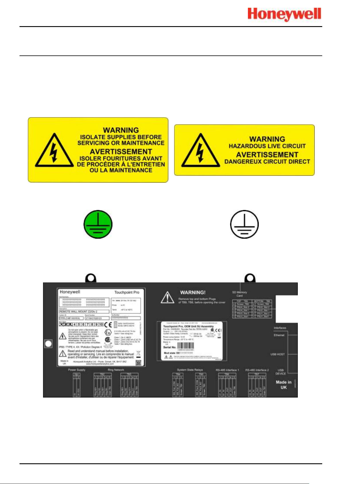
2.2 Location and Description of Warning Labels
2.2.1 Safety Warning Labels
Warning labels are mounted in specified locations on the equipment. This is to indicate conditions under which the user
could be subjected to electrical or other hazards.
Figure 1. Electrical Warning Label 1
Figure 2. Electrical Warning Label 2
Figure 3. Protective Earth (Ground) Point
Figure 4. Equipment Earth (Ground) Point
Note: Earth (Ground) Location Point labels are used inside the system and are not normally visible to the operator.
Figure 5. Controller Rear Cover with Example Labels
See next page for further information.
Page 18
SAFETY
Touchpoint Pro
Pt. No. 2400M2566_6_EN 9 Operating Manual
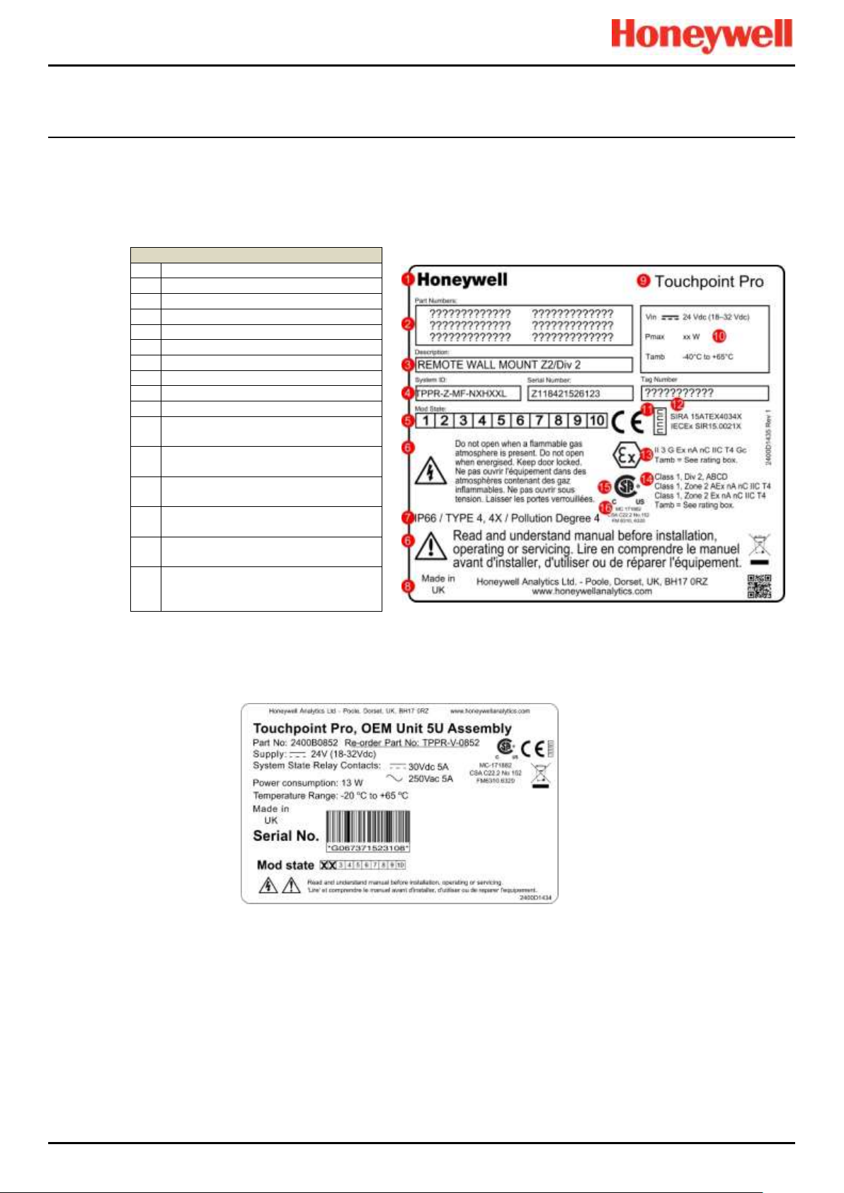
2.2.2 Equipment Rating Labels (Hazardous Locations)
The following labels are fixed in prominent positions on the enclosure and on relevant modules. It is the user’s responsibility
to check individual rating plates before installation and to ensure that specifications are not exceeded during operation.
Exceeding the approved ratings invalidates product certification and the manufacturers’ warranties.
Some early and OEM Controllers may not have the label shown in Fig. 5, but will have a label similar to the one in Fig. 6.
Key 1 Manufacturer
2
Part Numbers
3
Description
4
ID and Serial Number
5
Modification State
6
Safety Warnings
7
Ingress Ratings
8
Manufacturer Details
9
Equipment Title
10
Limits for Voltage / Power / T
amb
11
CE Mark and Notified Body for
Production Supervision
12
SIRA ATEX / IECEx Certificate
Numbers
13
ATEX / IECEx Hazardous Area
Certification Details
14
US/Canadian Hazardous Location
and Zone Certification Details
15
CSA Monogram Canada and USA
Certified
16
Manufacturer’s Master Contract
Number and Canadian / US
Performance Identification
Figure 6. Example of a Typical System Rating Label
Note: The CE mark and Notified Body number nnnn shown on product labels does not apply to Type ‘n’ approval.
Figure 7. Typical TPPR Product Label
Note: Similar labels appear on the Modules.
Page 19
SAFETY
Touchpoint Pro
Pt. No. 2400M2566_6_EN 10 Operating Manual
2.2.3 Warning Labels
The following symbols may be found on product labels and on the backup batteries:
Figure 8. Keep Children Away
Figure 9. No Naked Flames
Figure 10. Use Caution
Figure 11. Electrical Hazard
Figure 12. Read The Instruction Manual
Figure 13. Wear Eye Protection
Figure 14. Hazardous Waste
(Pb = Lead)
Figure 15. Recycle Only
Page 20

INTRODUCTION
Touchpoint Pro
Pt. No. 2400M2566_6_EN 11 Operating Manual
3 Touchpoint Pro Introduction
Touchpoint Pro (TPPR) is a Command and Control System designed for the Honeywell Analytics’ (and third party) range of
fixed sensors and detectors. It provides constant sensor monitoring with automatic alarm response and notification. Its alarm
levels and responses are fully customisable and all events and errors are logged on a removable SD card for easy archiving.
TPPR is certified to monitor hazardous areas such as Zone 2 Div. 2 via remote Z2D2 enclosures.
TPPR can be used indoors or outdoors, in pollution degrees 2 to 4, and up to IP66, depending on the enclosure that is used.
In addition it can be securely networked and either controlled or monitored via a secure network connection and the
Honeywell PC Configuration software or via the secure Honeywell Webserver browser interface.
Note: Both access methods are optional licensed extras. Please visit the Honeywell website for further information or to
download the Operating Instructions.
3.1 TPPR Access Levels
The table below details the access levels for the Local User Interface (UI). Broadly speaking, an Administrator can
commission modules and configure channels, an Engineer can edit channel configuration and do calibrations and testing,
and an Operator can acknowledge and reset events during normal day-to-day operation. Other users can view current and
historical events and trend data, and generate reports.
TPPR is supplied with a default Administrator level account. For security reasons this password will be attached to the
system Touchscreen. When the system is configured, at least one new Administrator account should be created. The
default Administrator should then log out and then log back in as the new Administrator, and should then delete the
default Administrator account to prevent unauthorized access. The Administrator can create other users with
Administrator level access or lower and the Maintenance Engineer can create users with Engineer level access or lower.
Note: Forgotten or deleted passwords cannot be recovered so it is advisable to keep a copy of the master password in a
secure place or have two Administrator accounts.
Authorised users can carry out the following tasks:
Key: Yes , No Read only ◼ Engineer and Operator ⧫
Task
Administrator
Engineer
Operator
Basic System Setup
Change Language
Change My Password
Configuring Channels
Configuring Modules
Configuring System
Diagnostics
Help / User Guides
Licence Management
⧫
User Management
◼
View and accept and
reset System Events
Generate Reports
Table 1. TPPR Access Levels
Note: Only Administrators can end another user’s active session.
Note: For security reasons some of these tasks are unavailable through PC Configuration and Webserver software. Refer to
the appropriate User Manual for more information.
Note: TPPR’s ability to Accept and Reset events can be restricted to authorised users by changing the software settings.
However, remote switches cannot be restricted through software so alternative switch protection methods should be used
where required.
Page 21
INTRODUCTION
Touchpoint Pro
Pt. No. 2400M2566_6_EN 12 Operating Manual
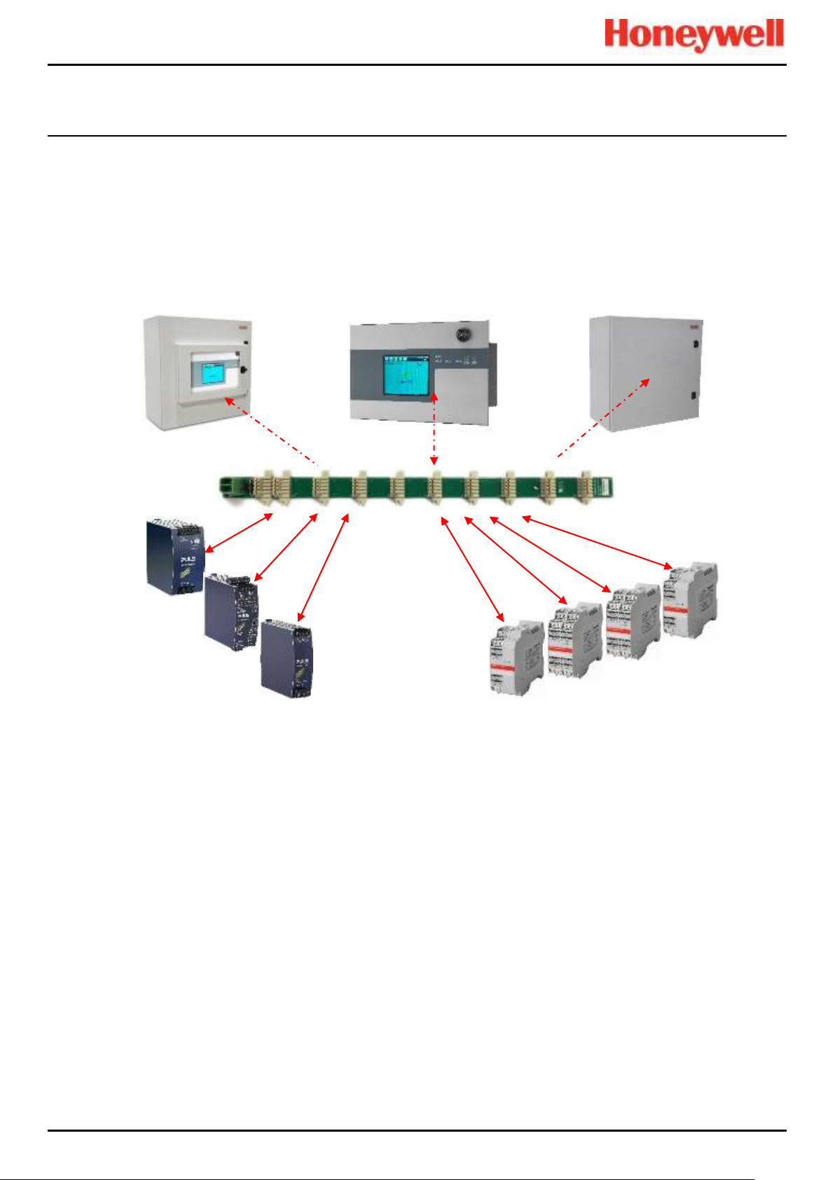
3.2 TPPR Control System Layout
The TPPR Control system can be built from just four main building blocks:
1. One Controller module with colour LCD touch screen User Interface
2. One backplane power and communications rail ( per enclosure or rack)
3. Power Supply modules (AC/DC, DC-UPS, Redundancy, Backup Battery)
4. Plug-in Input / Output (I/O) modules (mV, mA, AIM, DIM, ROM, AOM, Modbus)
Figure 16. TPPR Building Blocks
The illustration above shows wall mounted units but rack mounted and floor standing units use the same building blocks.
Enclosures can also hold multiple backplanes to allow for future system expansion.
Small Remote Unit
Controller Unit
Backplane
Controller
24 VDC Power Supply
(120/240/480 W)
24 V DC-UPS
Redundancy Module
(RDN)
Relay Output Modules
(ROM)
Digital Input Modules
(DIM)
mV/mA Analog Input Modules
(AIM)
Analog Output Modules
(AOM)
Page 22
INTRODUCTION
Touchpoint Pro
Pt. No. 2400M2566_6_EN 13 Operating Manual
3.2.1 Centralised Command and Control Option
TPPR can be installed as part of a centralised cabling system. With a centralised system, the field devices are individually
cabled back to the Controller and the field devices’ distance from the controller is limited only by the cable resistance and
whether or not power boosters are used.
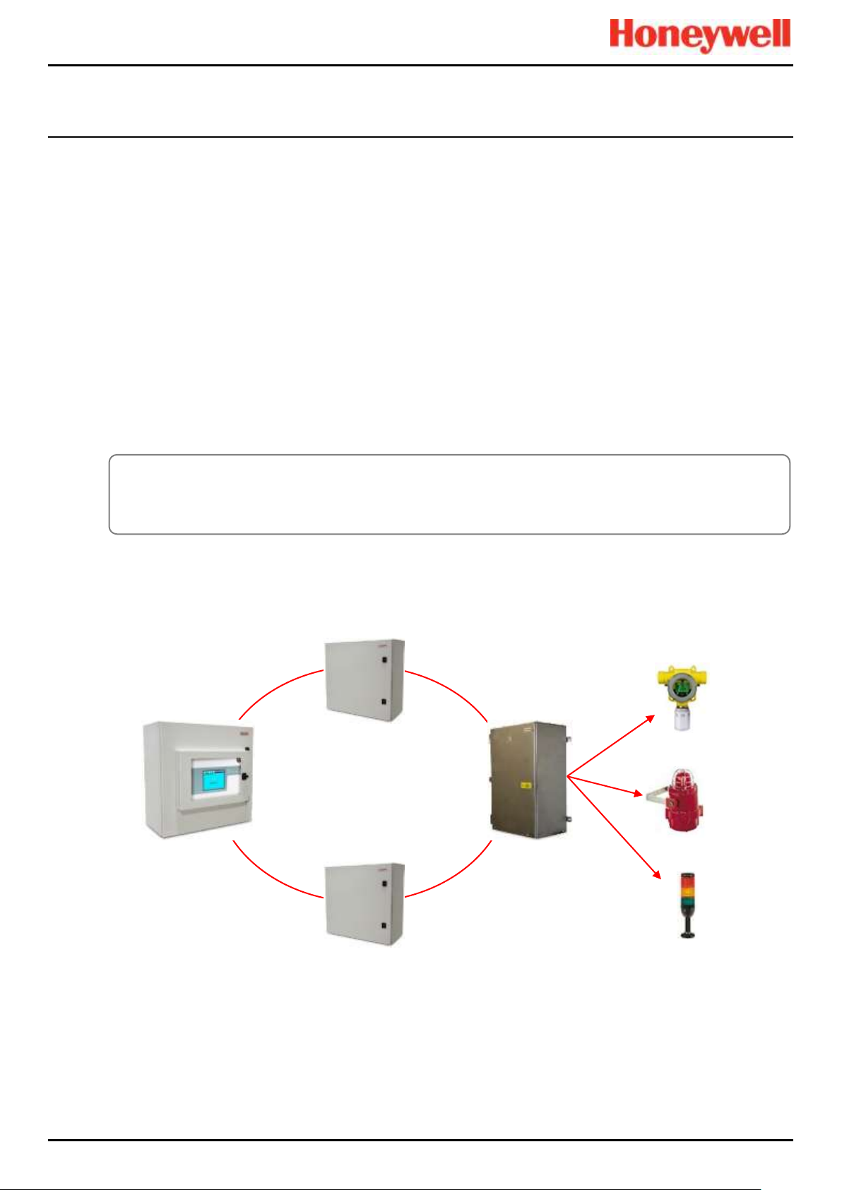
3.2.2 Distributed Command and Control (Remote Units) Option
TPPR can be installed as part of a distributed cabling system. In a distributed architecture, the field devices are connected
via short cable runs to TPPR Remote units, which are connected back to the controller by the Ring Network.
Remote units can be located up to 1 km (cable length) from the TPPR Controller or from each other, with a maximum cable
loop of 3 km for the complete system. The only connection required between the Controller and the Remote units is the
shielded network cable itself.
The TPPR Remote unit can be housed in any of the standard Enclosures, a 19” 5U rack, or a suitable 3rd-party enclosure. They do
not need a Controller but they do require their own power supplies.
Note: Standard Remote Units can be sited in safe areas to monitor and control devices sited in hazardous areas. You
should comply with all relevant legislation and you should follow the field device manufacturer’s installation and use
instructions.
The diagram below shows an example of a typical distributed setup showing both safe zone and zone 2 remote units.
Figure 17. TPPR Controller with Remote Units and Field Devices
Max. Loop 3 km
<1 km
<1 km
<1 km
<1 km
Sensors
Actuators
Lamp Stack
WARNING
You can install a Zone 2 Remote unit in Zone 2 to monitor sensors in ATEX Zone 1 provided that you use
appropriate barriers and armoured conduits, and that you follow all national and international cabling regulations.
Page 23
INTRODUCTION
Touchpoint Pro
Pt. No. 2400M2566_6_EN 14 Operating Manual
3.3 TPPR System Key Components
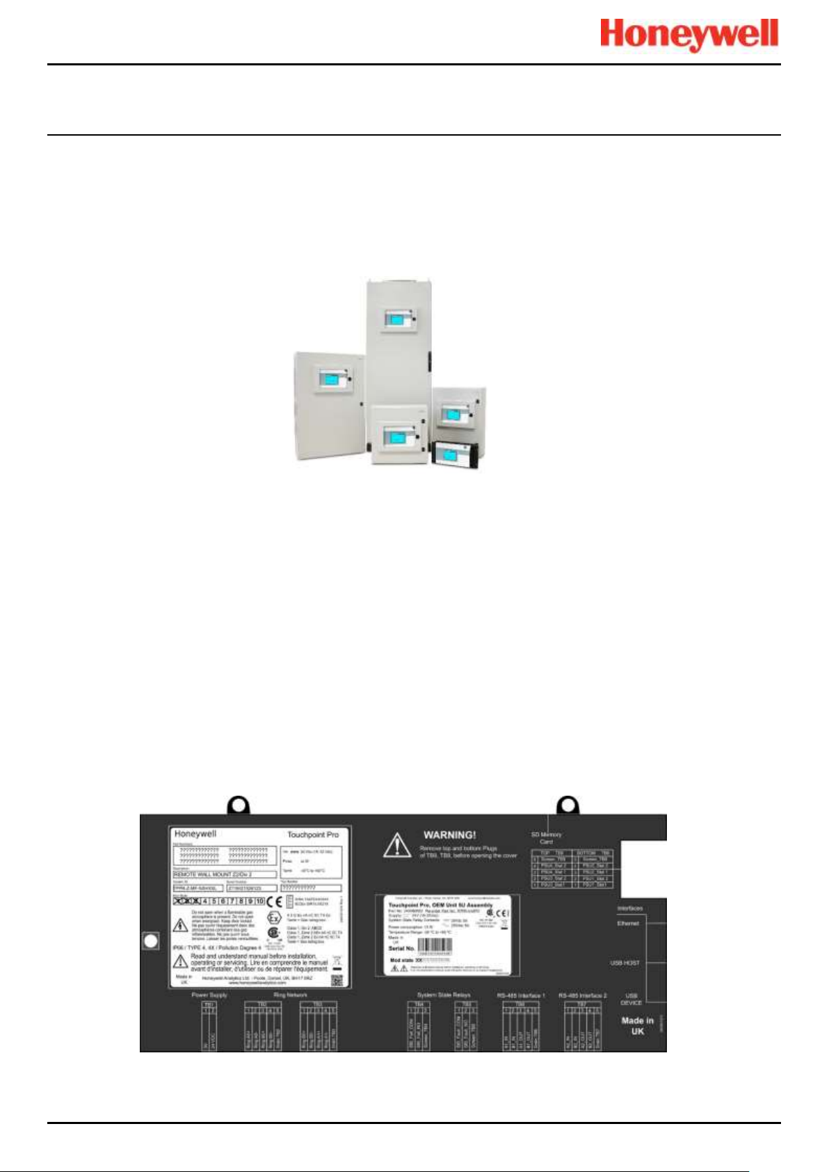
3.3.1 Enclosures and Racks
TPPR can be mounted in various sizes of floor or wall mounted enclosures, or on 19” 5U racks. The floor mounted
enclosures can be unventilated, naturally ventilated, or force ventilated. The fully sealed wall mounted enclosures can hold a
controller or can be a remote terminal without a controller.
If using a 19” rack, the OEM or installer must ensure the installation is at least IP20 / Type 1 / Class 1 (grounded) to mitigate
the risk of electrical shock.
Figure 18. TPPR Enclosures
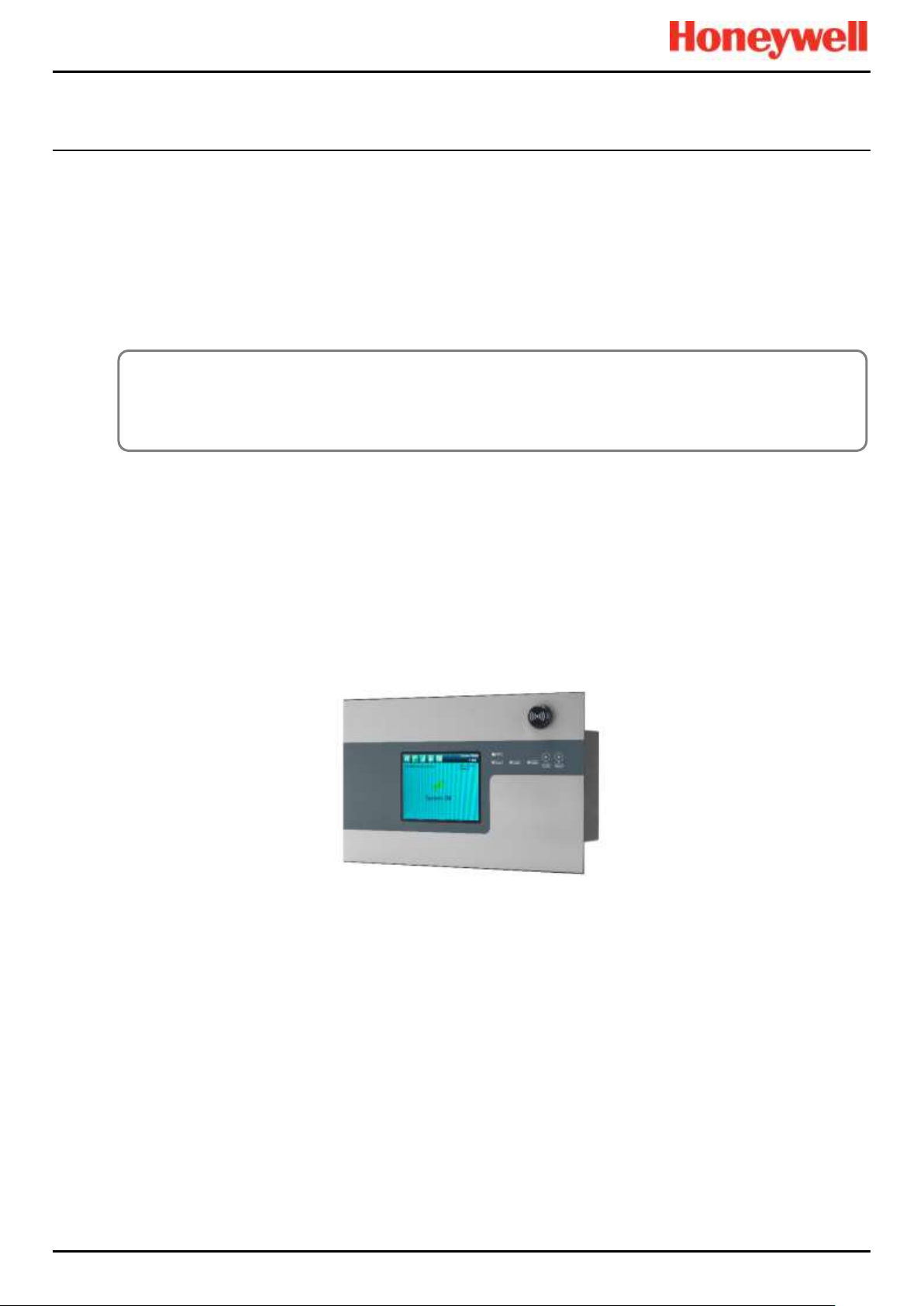
3.3.2 TPPR Controller User Interfaces
The TPPR Controller is covered with a protective membrane and houses the touch screen user interface (UI), the alarm
buzzer, the Accept and Reset buttons, and coloured LEDs for Power, Alarm, Fault, and Inhibit.
The controller has four access methods:
• Control Panel touch screen for normal system operation, maintenance and configuration
• PC Configuration Software (optional licences) for secure maintenance and configuration over a VPN or cable
• Webserver (optional licences) allows up to 5 people to securely view events and carry out basic system operation via
an Ethernet connection or the Internet
• Modbus option
Internal System Interfaces consist of:
• Two master relays that signal System Failure and System Fault
• Connections for one SD Card and one USB drive
• 10/100 Mbps Ethernet connection (for networked interfacing)
• Optional dual RS 485 Modbus RTU interface
Figure 19. TPPR Controller Cover with Connection Map
Page 24

INTRODUCTION
Touchpoint Pro
Pt. No. 2400M2566_6_EN 15 Operating Manual
3.3.3 SD Card
TPPR is supplied with an installed 4GB SD card, which users may replace with a larger capacity if desired.
The SD card is used to store the event history of the system. TPPR logs all events and all changes to input readings.
Note: The SD Card should remain inserted during normal system operation as the motherboard has limited data storage
capacity.
3.3.4 USB Port
The USB Host port allows users to save reports, backup and restore configuration.
Note: USB devices must be formatted to FAT32 only; other file systems are not supported and will not work.
Note: The USB device is intended for maintenance and support operations only, and should be removed for normal use.
3.3.5 PC Configuration Software
This optional (downloadable) licensed software allows authorised users to configure some TPPR settings by using a remote
PC over an Ethernet connection. This is more efficient as you can use a larger screen and keyboard.
More information is available in a separate PC Configuration User Guide, downloadable from www.honeywellanalytics.com.
3.3.6 PC Operating Systems
Windows 7, 8 and 8.1 are supported for use with PC Configuration and Webserver; other operating systems may work but
are not supported.
3.3.7 Webserver Software
This optional (pre-installed) licensed software allows users to remotely view live status, and analyse event history.
Authorised users can also acknowledge, inhibit and reset I/O channels.
The Webserver supports up to 5 concurrent web clients. More than 5 clients can connect but performance may degrade.
More information is available in a separate Webserver Operating Manual.
3.3.7.1 Supported Web Browsers
TPPR software is compatible with most current web browsers.
CAUTION
Honeywell will not be held liable for any loss or damage caused by any security breach, no matter how caused.
Page 25
INTRODUCTION
Touchpoint Pro
Pt. No. 2400M2566_6_EN 16 Operating Manual
3.3.8 Licences
The TPPR controller software does not require a licence.
Please contact your local Honeywell supplier or distributor to obtain licences for the optional PC Configuration and
Webserver options.
Refer to the PC Configuration or Webserver User Guides for details on installing and managing licences.
TPPR will notify you shortly before the expiry of your current PC Configuration or Webserver licence. Licence expiry does
not affect local operation using the local controller’s interface.
3.3.9 TPPR Controller Hardware
Internally the Controller houses the Control Centre Board (CCB) and the Communications Board (COB). It also contains an
SD Card slot, USB ports and an Ethernet / Printer port.
The CCB handles all functions related to the safety system operation, the Ring network, the LED indicators and buttons on
the front panel, and the master system state relays. An optional backup CCB is available for multiple redundancy
specifications.
The COB handles the remaining user interfaces (UI) – Touchscreen, bus output and the SD, USB and Ethernet ports.
The Communication Board is completely independent from the Safety Function of the system.
Figure 20. TPPR Controller
CAUTION
Always follow the correct procedure to remove/suspend/reinstall a licence if your system software or firmware is
going to be updated or repaired. Full details are contained in the PC Configuration and Webserver User Manuals.
Page 26
INTRODUCTION
Touchpoint Pro
Pt. No. 2400M2566_6_EN 17 Operating Manual
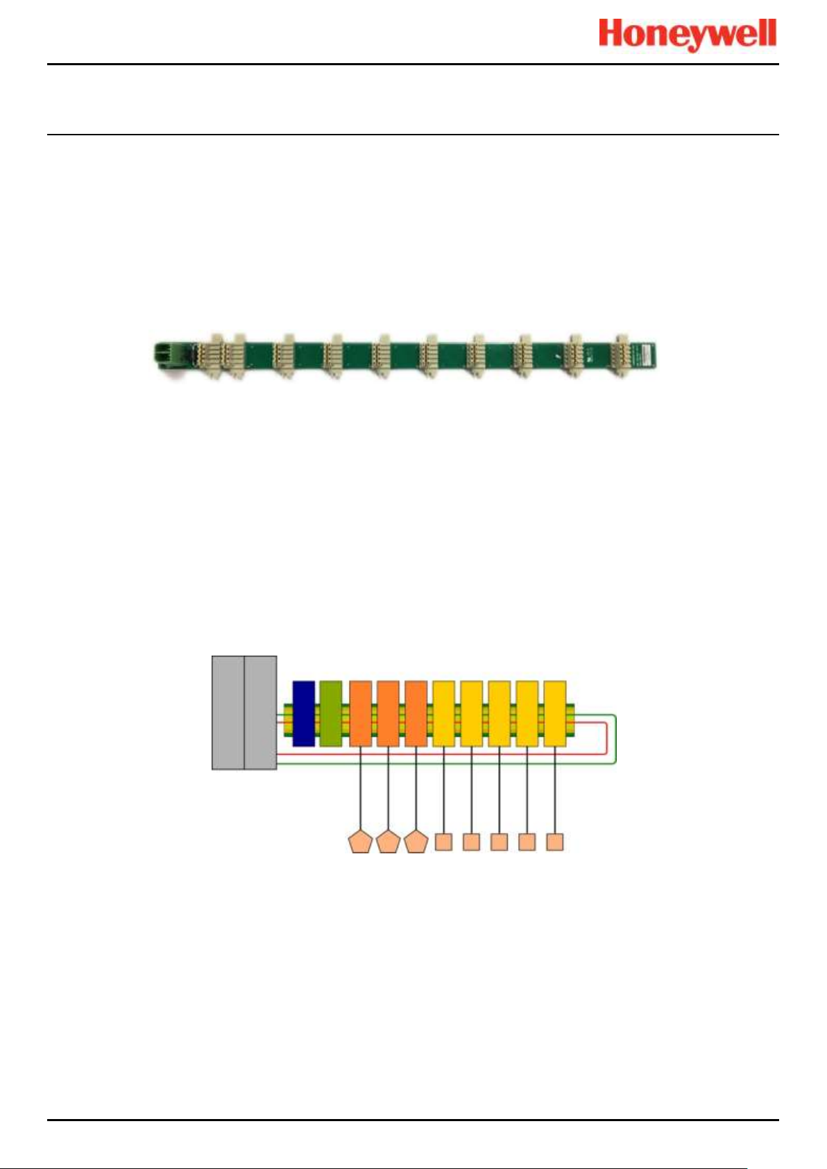
3.3.10 TPPR Backplane
The TPPR Backplane is the power and information highway to which all of the TPPR modules are attached. There can be
several backplanes in larger units, and they are installed within the DIN rail to which the modules are clipped.
The Backplane is available in four lengths (270 mm, 350 mm, 430 mm, 480 mm) to suit 5, 7, 9 or 10 I/O modules
respectively, but the choice may be restricted by the size of the selected power supply option and the need to maintain
adequate cooling space between modules.
Note: The DIN rail is 430 mm for a standard enclosure or 487 mm for the wide enclosure (10 x I/O) option.
Figure 21. TPPR Backplane
The power supply plugs into one of the green sockets on the left hand side of the backplane and supplies power to the
modules via the module connectors. The Ring Coupling Module (RCM) is normally positioned next to the power connector
and facilitates bi-directional communication between the CCB and the modules again via the module connectors.
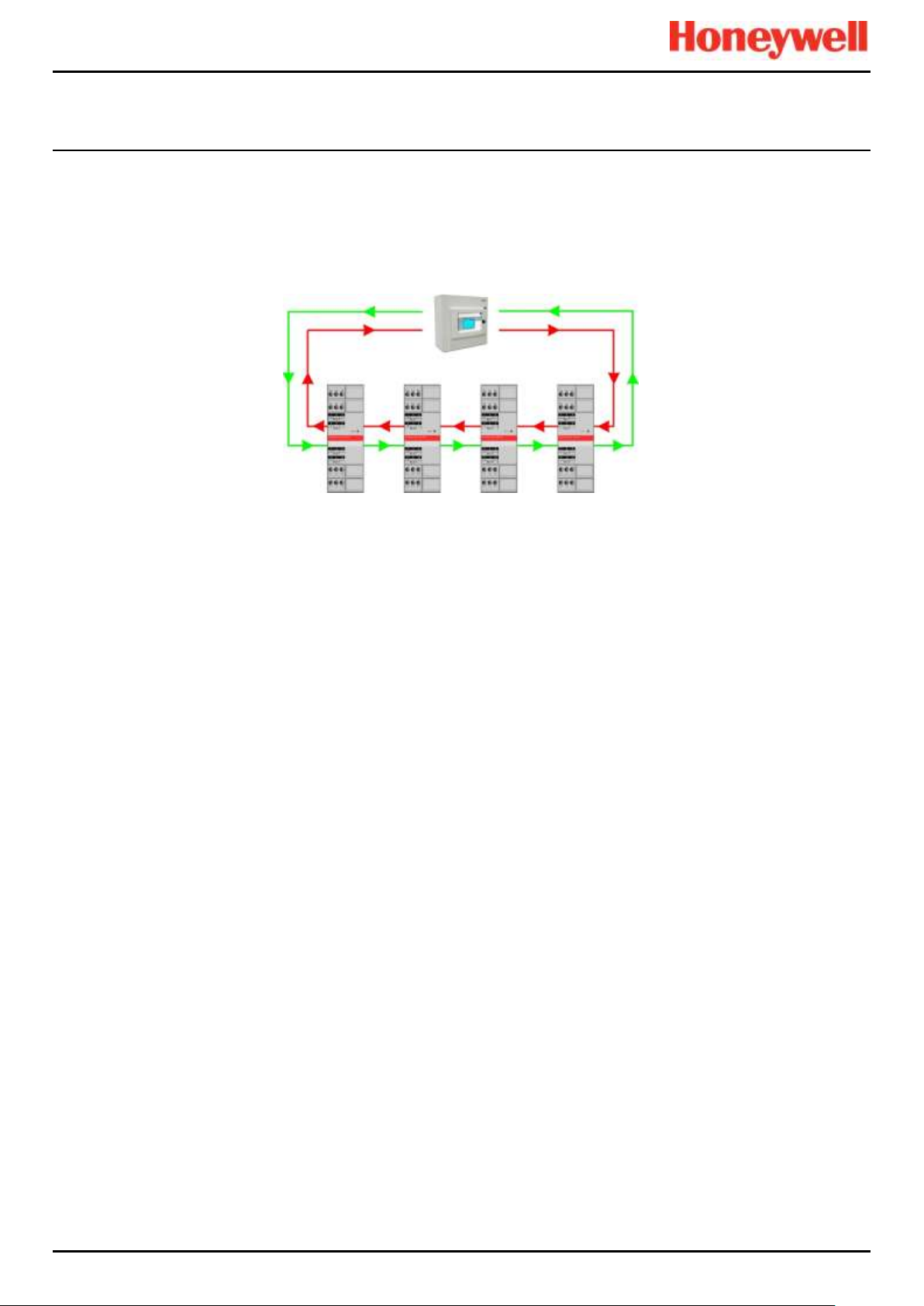
3.3.11 Ring Network
The Ring Coupling Module (RCM) and Input / Output (I/O) modules connect to a dual ring circuit so that they can
communicate with the CCB through each other and through the RCM.
This enables fail-safe redundancy because, if one addressable module fails and interrupts the primary circuit, the
addressable modules on either side of it can still communicate with the CCB via the backup ring circuit (see diagram below),
and the CCB can identify which module has failed by knowing which addressable modules are still active.
Figure 22. TPPR Controller Typical Schematic
Gas Detectors
TPPR- Activated Field Devices
Output Modules
Input Modules
Backplane
DIN Rail
Ring 'A'
Ring 'B'
Redundancy
Circuits
Communication Board
(COB)
Control Centre Board
(CCB)
TPPR Controller
PSU
RCM
24 V DC
PSU Input
RCM
Sensor
Input Modules
Field Device
Output Modules
RCM Redundancy
Module (option)
Page 27
INTRODUCTION
Touchpoint Pro
Pt. No. 2400M2566_6_EN 18 Operating Manual
For single cabinet installations, the Ring Network runs directly between the RCM and the Control Module.
For Remote units, the network runs additionally over data cable between the Controller and all of the backplanes in the
system.
The Ring Network is the only communication link required between the CCB and Remote Units (which have their own
backplanes, PSU and modules, but no Control Module).
Figure 23. Example Ring Circuit
Page 28
INTRODUCTION
Touchpoint Pro
Pt. No. 2400M2566_6_EN 19 Operating Manual
3.3.12 TPPR Modules
TPPR is of modular construction so it can be easily expanded if required. The quantity and mix of I/O modules is optional
and expandable.
• Power Supply Unit (PSU) modules accept AC 120 – 240 V at 50/60 Hz single phase and are available in three power
outputs: 24 VDC @ 120, 240 or 480 W.
• The optional DC-UPS is an uninterruptible DC power supply that links to and charges the optional 2 x 12 V Sealed
Lead Acid backup batteries.
• The optional Redundancy Module (RDN) can control two DC 20 A power inputs. If one input supply fails, the
Redundancy Module will switch over to the other, maintaining the DC output. Alarm relays will open if one of the input
supplies fails.
• The Ring Coupling Module (RCM) enables fail-safe bi-directional (ring network) communication between modules and
the controller. An RCM is required for each backplane in the system.
Various types of I/O modules are available, each containing four channels. A single TPPR system can contain up to 16 input
modules offering 64 input channels and up to 32 output modules offering 128 output channels.
Title
Description
Analog Input Module 4–20 mA (AIM mA)
4-channel Analog Input Module for 2 or 3 wire 4-20mA sensor signals
Analog Input Module mV Bridge (AIM mV)
4-channel Module for mV-Bridge signals; supports up to 4 catalytic bead
flammable gas sensors
Digital Input Module (DIM)
4-channel Module for switched input devices such as manually operated
push buttons. Can also be used for remote access to alarm acknowledge,
reset and output inhibit inputs
Relay Output Module (ROM)
4-channel Module incorporating qty 4 SPCO (NO/NC) relays; suitable to
activate field mounted external alarms, actuators, drenching or shutter
systems, or to de-activate magnetic exit controls etc.
Analog Output Module (AOM)
4-channel Analog Output Module for 2 or 3 wire 4-20mA/0-20mA output
signals
Table 2. TPPR Module Types
Figure 24. TPPR Module Types
3.3.13 Sensor Catalogue
The TPPR Controller is pre-loaded with an updatable sensor catalogue that lists all of Honeywell Analytics’ current gas
sensors, each with a full default configuration setting that can be loaded when commissioning the Input modules. The full
configuration can be viewed afterwards, and individual parameters changed if desired.
The full procedure is explained in the TPPR Technical Handbook, Ch.7 Software Setup and Commissioning.
Relay Output Modules
(ROM)
Digital Input Modules
(DIM)
mV/mA Analog Input Modules
(AIM)
Analog Output Modules
(AOM)
24 VDC Power Supply
(120/240/480 W)
24 V DC-UPS
Redundancy Module
(RDN)
Page 29
INTRODUCTION
Touchpoint Pro
Pt. No. 2400M2566_6_EN 20 Operating Manual
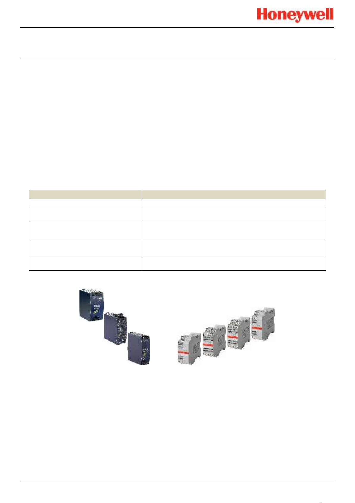
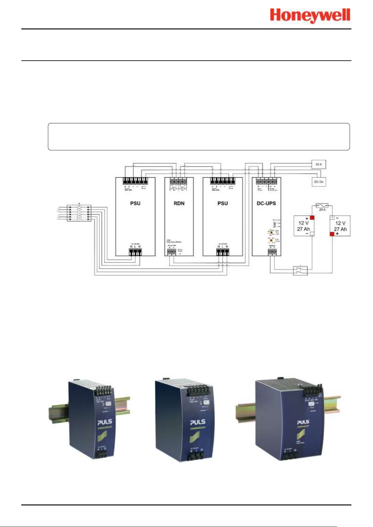
3.4 Power Supply Options
TPPR can be supplied from an AC 110/240 V Single Phase industrial supply via the optional Power Supply (PSU) Modules,
or from a direct DC 24 V power supply, or from optional 24 VDC backup batteries via the DC Uninterrupted Power Supply
module (DC-UPS).
When specifying power supplies, you should consider cabinet internal temperatures and cooling. In addition, power supplies
should be rated to allow for current surges and peaks. Contact your Honeywell representative for advice.
Figure 25. Typical Power Supply Setup
A full description of the available module types is given in the following sections.
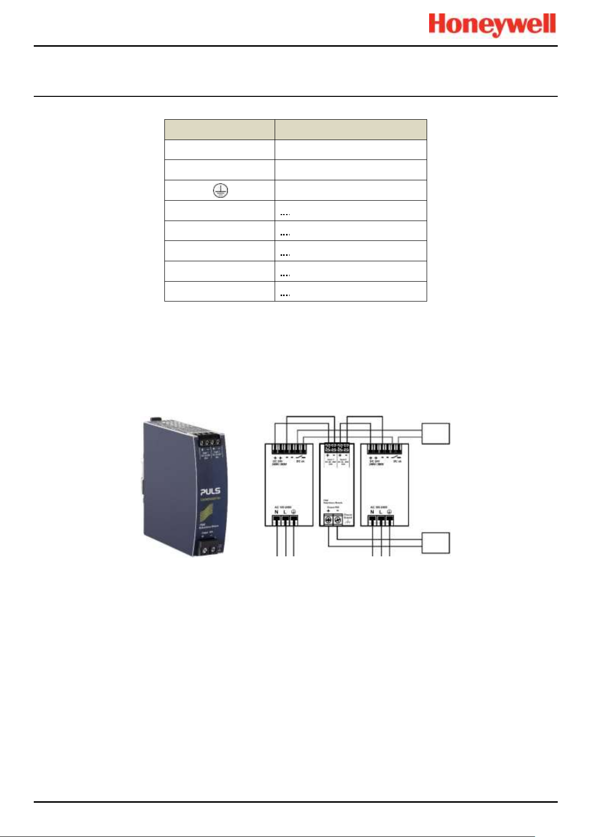
3.4.1 Power Supply Unit Modules (PSU)
The TPPR System can be equipped with PSU modules of different capacity, depending on the number of I/O modules being
used. The power supplies are mounted to the DIN-Rail and are available in the following ratings:
• 120 W, 24 – 28 VDC (5 A @ DC 24 V)
• 240 W, 24 – 28 VDC (10 A @ DC 24 V)
• 480 W, 24 – 28 VDC (20 A @ DC 24 V)
The power supplies have a 'DC Ok' status output that can be used to give a fault warning on failure.
Figure 26. Choice of PSU Size (120 W / 240 W / 480 W)
AC Mains
AC Generator
Load
Main Isolator
Circuit Breaker
Battery
Isolator
WARNING
AC power supplies must have a permanent connection to a protective earth, according to local regulations.
Page 30
INTRODUCTION
Touchpoint Pro
Pt. No. 2400M2566_6_EN 21 Operating Manual
Terminal
Purpose
N
~ AC 110/240 V Neutral In
L
~ AC 110/240 V Line In
Protective Earth (Ground)
+
— DC 24 – 28 +V Output 1
+
— DC 24 – 28 +V Output 2
–
— DC –V Output 1
–
— DC –V Output 2
DC OK
— Relay Contacts 1 & 2
Table 3. PSU Terminal Allocation
3.4.2 Power Redundancy Module (RDN)
The RDN is an optional power supply backup system that can be installed with a second PSU to offer dual power supply
redundancy. Often the Mains supply will be connected to the first PSU and a stand-by generator connected to the second
PSU. The RDN will take power from either input and output it as a single source. See diagram below for cabling details.
Note: The RDN Output can also provide further redundancies via an optional battery backup and DC Uninterruptible Power
Supply (DC-UPS) module.
Figure 27. Power Redundancy Module Operation
Failure
Monitor
20 A
Load
Page 31

INTRODUCTION
Touchpoint Pro
Pt. No. 2400M2566_6_EN 22 Operating Manual
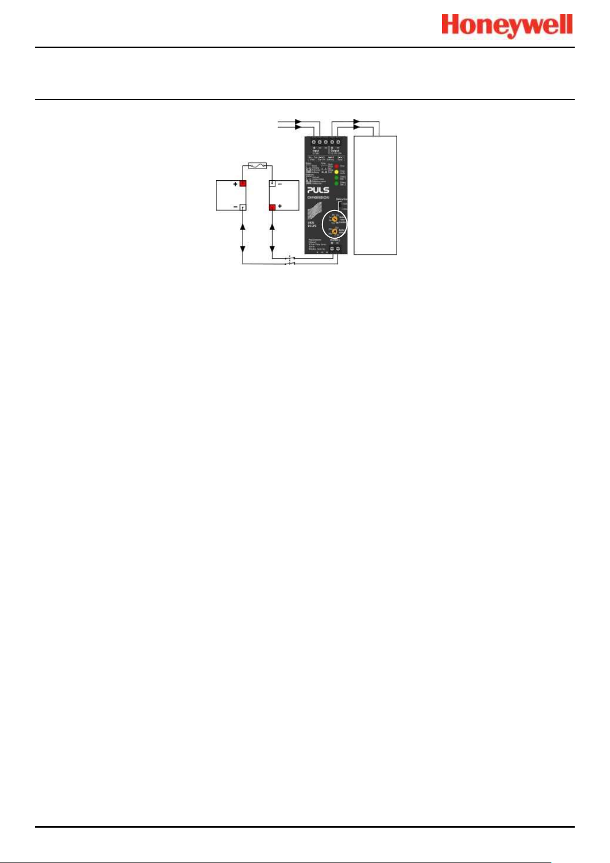
3.4.3 DC Uninterruptible Power Supply (DC-UPS) Module
The DC-UPS Module can be used with the separate and optional TPPR Battery Enclosure to provide continuous and
uninterrupted power to the TPPR in the event of an external power failure.
The DC-UPS is adjustable for buffer time and buffer voltage, and carries red, yellow and green status LEDs and descriptions
that show your backup battery status (see tables below).
Note: The DC-UPS Module Buffer Voltage should be set at 26 VDC to ensure optimum battery charging, and the Buffer-time
Limiter should usually be set to ∞ (see circled area on the figure below).
Figure 28. DC-UPS and Battery Configuration
The DC-UPS terminals are as follows:
DC-UPS Terminal
Purpose
Input +
+24 VDC input from UPS
Input –
–24 VDC input from UPS
Input –
–24 VDC input from UPS (spare)
Output +
+24 VDC output to 20 A (max) Load
Output –
–24 VDC output to 20 A (max) Load
Battery +
+24 VDC Battery in/out
Battery –
+24 VDC Battery in/out
Table 4. DC-UPS Primary Terminal Allocation
The DC-UPS also has Normally Open (NO) relay terminals that can be used for external repeaters such as a lamp stack or
alarm buzzer, as shown in the table below:
DC-UPS Terminal
Purpose
1 & 2
Ready relay: Closed when all is Ok (green)
3 & 4
Buffering relay: Closed when batteries are supplying power (yellow or buzzer)
5 & 6
Replace Battery relay: Closed when batteries fail load test (red or buzzer)
7 & 8
Do not use as Inhibit belongs to the Controller only
11 – 13
Not normally used
Table 5. DC-UPS Secondary Terminal Allocation
20 A
20 A max
Load
12 VDC
Battery
12 VDC
Battery
24 VDC 24 VDC
Isolator
Switch
Page 32
INTRODUCTION
Touchpoint Pro
Pt. No. 2400M2566_6_EN 23 Operating Manual
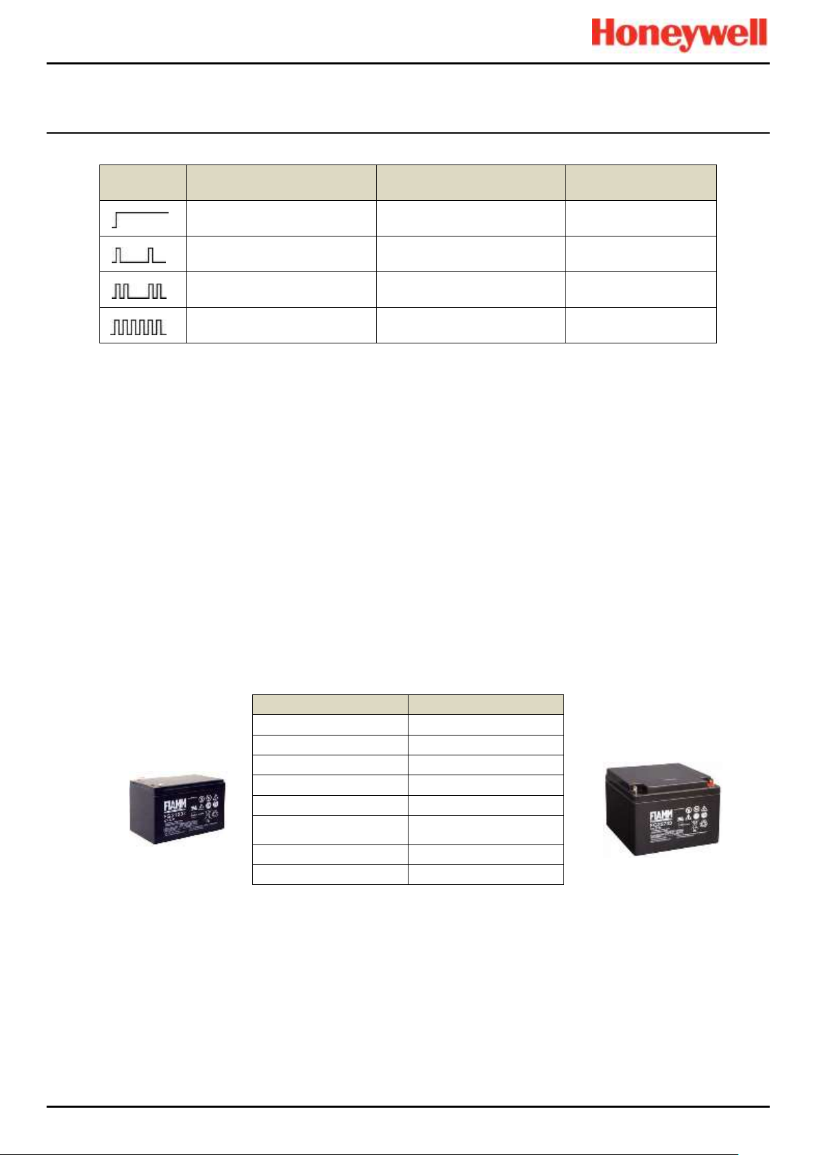
LED Flash
Green Status LEDs
Yellow Diagnosis LED
Red Error LED
Steady means
DCUPS ready
Steady means
Power Overload
Steady means
Check the wiring
Single flash means
Charging
Single flash means
Replace Batteries
Single flash means
Check Input voltage
Double flash means
Refreshing
Double flash means
Buffer time expired
Double flash means
Over Temperature
Continuous flashing means
Buffering
Continuous flashing means
Inhibit Active
—
Table 6. DC-UPS LED Meanings
3.4.4 Backup Batteries
The optional Battery Enclosure contains two rechargeable 12 V batteries wired in series to give a nominal 24 VDC supply.
The batteries can be either 12 Ah or 27 Ah and they are overload-protected by a 20 A fast acting inline cartridge fuse.
A new set of 12 / 27 Ah batteries should supply 22.5 V at 20 A for up to 16.75 / 32 minutes respectively, depending on the
connected load. However, you should be aware that all batteries deteriorate over time, and Honeywell recommend that you
check and replace them regularly to ensure optimum performance in an emergency.
Note: Always switch the Battery Isolator switch to Off before carrying out any work on the battery circuit, and ensure it is On
when work is completed.
The 12V monobloc batteries are Valve-Regulated Lead Acid (VRLA) Absorbed Glass Mat (AGM) batteries that:
• Are optimized for discharge (buffer) times of up to 20 hours @ 3 A.
• Have a 5 year design life in float operation in temperature controlled environments.
• Have VRLA AGM and gas recombination technology with 99% internal recombination.
• Are non-spillable and maintenance free.
• Are non-hazardous when packaged for air/sea/rail/road transportation.
• Are 100% recyclable.
Table 7. Backup Battery Details
12 / 27 Ah Battery (pair)
Stand-by Use
Charge Voltage (max)
27 V
Input Current
3 A
Max Output Current
20 A
Max Load
30 A <4 Sec.
Fuse type (inline)
20 A Fast Acting Tube
Current Limit Protection
20 A Double-pole Circuit
Breaker / Isolator,
Weight 12 Ah
3.75 kg (ea.)
Weight 27 Ah
8.5 kg (ea.)
Page 33
INTRODUCTION
Touchpoint Pro
Pt. No. 2400M2566_6_EN 24 Operating Manual
Figure 29. Battery Circuit
20 A
20 A max
Load
12 VDC
Battery
12 VDC
Battery
24 VDC 24 VDC
Isolator
Switch
Page 34

CONFIGURATION
Touchpoint Pro
Pt. No. 2400M2566_6_EN 25 Operating Manual
4 Configuration Files
4.1 Viewing and Editing the Configuration
TPPR systems are normally configured to the customer’s requirements on manufacture, but you can view and edit the
configuration if required.
A configuration timeout is activated when you enter the System Setup menu and you will be logged out of configuration if no
values are sent to the system for 20 minutes. Any changes that have already been sent to the system will be retained, but
any that have been made but not yet sent to the system will be lost. It may be necessary to login and return to System
Setup and set the module to Normal State before retrying the edits.
4.1.1 To View or Edit the Configuration
1. Log in as an Administrator or Engineer.
2. From the System Status screen select the Tool Box icon then System Configuration.
3. Re-enter the password and select Login.
4. Select System Setup.
5. Select the required module, and then click the Menu icon.
6. Select Edit Configuration and then follow the on-screen menus.
7. The screen will show the system setup tree listing all installed I/O modules and Control Centre Board(s).
8. Select the + beside each module to expand and show its four channels.
9. Select the required channel, select the Menu icon and select Edit Configuration.
10. Select the screen that you want to edit (refer to the previous sections).
11. Enter the required New Value and select Send.
12. The system will show the new values; select Accept.
13. Either edit another channel or Log out.
You should back up the TPPR system configuration once commissioning is completed, and again after any changes to the
setup or software. The TPPR safety system remains operational during this procedure but the controller touch screen, PC
Configuration software and Webserver may not be used.
The configuration may be backed up to SD card or USB drive. Backups are stored to a dedicated folder on the SD card or
USB drive. Backup files are allocated a sequential number to allow the latest backup to be identified.
The sequence number is determined by examining the files already present in the backup’s directory. If more than one
storage device is used, the same number may be used on each device. A consistent backup regime should be used to
prevent data loss or confusion.
If backing up to SD card, the installed event logging SD card is normally used. This card may be briefly removed to copy the
backup file to a PC but the card should be refitted as soon as possible to avoid data loss.
It is possible to back up to a replacement SD card but any events that occur during the backup process will be logged to this
SD card and will not be available in the event history when the card is removed.
Note: Engineer access level is required to back up the configuration. Administrator access level is required to restore
configuration.
WARNING
Only Honeywell trained and authorised persons or qualified persons trained in accordance with the Touchpoint Pro
Technical Handbook should edit, restore or delete configurations as errors can adversely affect system functions.
Page 35

CONFIGURATION
Touchpoint Pro
Pt. No. 2400M2566_6_EN 26 Operating Manual
4.2 To Back Up the Configuration
1. Ensure that the destination drive is inserted in the Control Module.
2. Login as an Engineer.
3. From the System Status screen select the Tool Box icon then System Configuration then System Management.
4. Re-enter the password and select Login.
5. Select CCB Management and click on Configuration Backup:
6. Select the required drive.
7. The system will display a message ‘The configuration backup process might take a few minutes. The User Interface
is not accessible during this time. Do you want to proceed?’ Ensure that destination drive is always connected during
this operation.
8. Once the action is confirmed, the configuration backup process starts and a progress message is displayed. The
backup may take several minutes depending on the system size.
9. The Configuration backup file is stored on the memory device in:
TPPR Configuration\TPPR_Config_SystemID_<sequence>.bin
e.g.: TPPR_Config_SYSTEMSPL0003_009.bin
4.3 Restoring the Configuration
Refer to the Touchpoint Pro Technical Handbook.
4.4 Deleting the Configuration
The Administrator has the option to delete the system configuration. This option is for specific circumstances only, and is
not intended for normal use. Refer to the Touchpoint Pro Technical Handbook for further information.
Page 36

Normal Day-to-Day Operation
Touchpoint Pro
Pt. No. 2400M2566_6_EN 27 Operating Manual
5 Normal Day-to-Day Operation
There are several methods of interacting with TPPR:
• Controller Touchscreen (Supplied)
• PC Configuration Software (Licensed Option)
• Webserver (Licensed Option)
• Modbus (Option)
5.1 TPPR Controller Touchscreen Interface
The Touchscreen allows authorised users direct control of all of the TPPR functions. These functions are fully described in
the TPPR manual suite.
5.2 TPPR PC Configuration Software Interface
PC Configuration software is an optional remote method for accessing the TPPR via a secure local Network connection.
The PC Configuration tool allows an authorised remote user to configure the controller, and to remotely view or amend the
controller configuration.
The PC Configuration Interface is broadly similar to the Touchscreen Interface described in this manual. Refer to the
downloadable PC Configuration User Guide for information on licensing, setup and day-to-day running.
PC Configuration software requires the TPPR controller to be configured with a unique static IP address, which is normally
obtained from your site IT department.
Note: You may need Administrator privileges on the host PC.
5.3 TPPR Webserver Interface
The Webserver Interface is an optional remote method for accessing the TPPR display and viewing live TPPR events via an
Ethernet connection. Events can be acknowledged and reset using the appropriate access passwords and event history can
be analysed. Reports can be generated and saved or viewed on the client computer or device.
The Webserver allows an authorised remote user to Accept and Reset events on the controller, and to Inhibit channels, or
clear Inhibits.
The Webserver Interface is broadly similar to a limited version of the Touchscreen Interface described in this manual. Refer
to the downloadable Webserver User Guide for information on licensing, setup and day-to-day use.
The TPPR controller requires a static IP address for use with the Webserver, normally obtained from your site IT
department.
Page 37

Normal Day-to-Day Operation
Touchpoint Pro
Pt. No. 2400M2566_6_EN 28 Operating Manual
5.4 TPPR Safety Function
During normal Day-to-Day operation:
• The TPPR system will collect data every 250 ms from all of the Input/Output modules on the Ring Network
• The Cause and Effect matrix will be evaluated every 250 ms, and commands sent accordingly to the appropriate
output channels. System response time for AIM is ≤3 s and ≤1 s for DIM
• Any change in status of an I/O channel will be reported to the User Interface and logged in the event history
• Any occurrence of any of the events listed in the TPPR Technical Handbook, Ch.11 Error Codes, will be reported on
the User Interface and logged in the event history
• Any system fault or inhibit will cause the System Fault relay to open.
• Any failure of the safety function e.g. due to major fault or power loss will cause the System Failure relay to open.
5.5 Touchscreen Operation
During normal operation the Touchscreen should show a menu bar at the top and a green tick on the main screen below it.
During active events the status changes and an alarm may sound.
Users may touch the screen to show further menus or descriptions (some menus require password access).
A table of icons is given in the TPPR Technical Handbook, Ch.17 Table of Icons.
5.5.1 System Status Screen Alert Icons
The System Status screen provides a summary of the TPPR status using Alert Icons accompanied by the text in bold:
System OK
All input and output
channels are Normal
Fault
One or more channels are
in Fault
Alarm
One or more input channels
are in Alarm
Inhibit
One or more channels are
in Inhibit
Warning
One or more Warnings are
active
Table 8. System Alert Icons
WARNING
High ‘off-scale’ readings may indicate an explosive concentration.
AVERTISSEMENT
Des résultats dépassant considérablement l’échelle peuvent être indicateurs d’une
concentration explosive.
Page 38

Normal Day-to-Day Operation
Touchpoint Pro
Pt. No. 2400M2566_6_EN 29 Operating Manual
5.5.2 Active Event History
The Active Events screen lists the current event history in the order that the events occurred, and in colour (Red, Yellow,
Orange and Grey) to highlight the severity. TPPR has the option to filter the history into categories, and this is described in
Chapter 6.8 Responding to Alarms, Faults and Warnings.
5.5.3 Touchscreen Layout
The two main Touchscreen displays are shown in the figure below. The top row shows touch sensitive icons as described in
the TPPR Technical Handbook, Ch.17 Table of Icons.
Figure 31 may be accompanied by external beacons, sounders and other events depending on your system setup. You can
touch each of the alarms, faults or warnings to identify the cause and to acknowledge them as described later.
Figure 30. System Status Normal
Figure 31. System Status with Example Active Events
Page 39
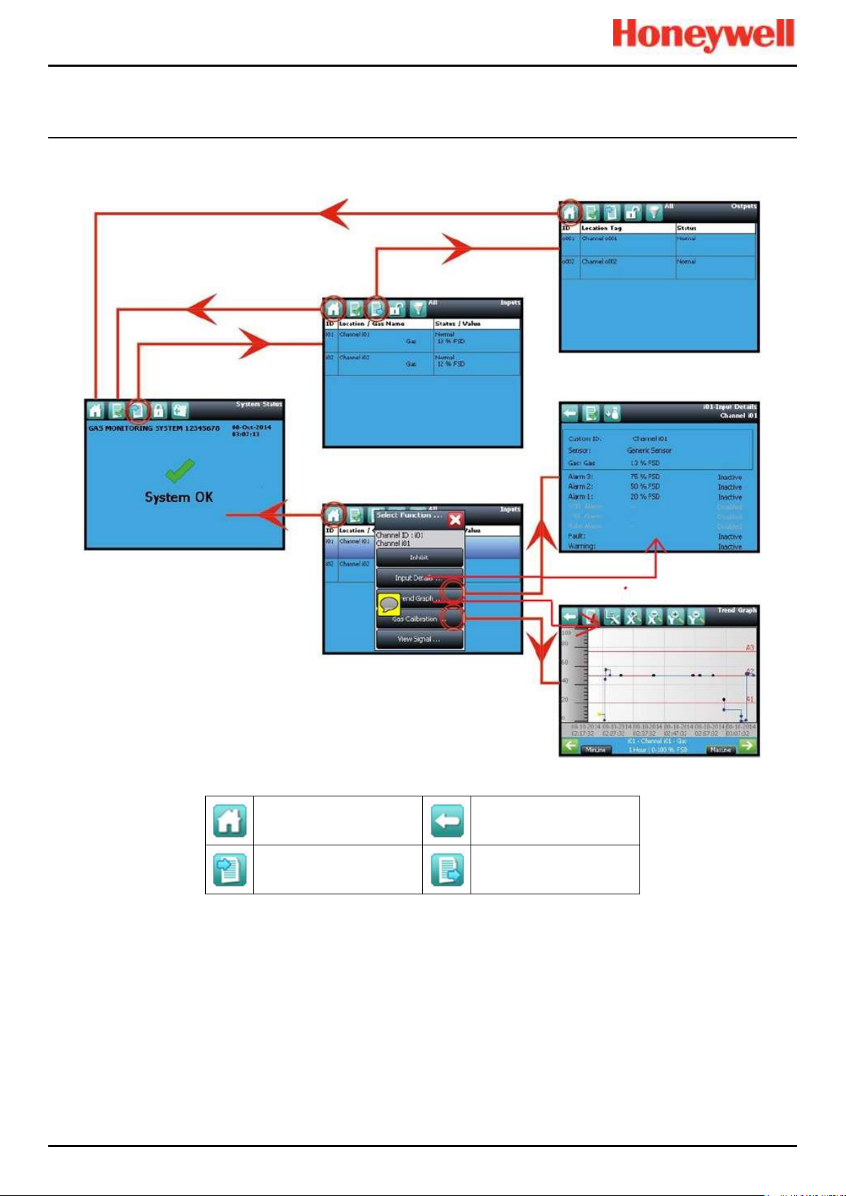
Normal Day-to-Day Operation
Touchpoint Pro
Pt. No. 2400M2566_6_EN 30 Operating Manual
5.5.4 Touchscreen Navigation
The icons in the navigation bar are used to navigate through the User Interface Software.
Key
System Status (Home)
Back
Inputs
Outputs
Figure 32. Touchscreen Navigation – Input and Output
Page 40
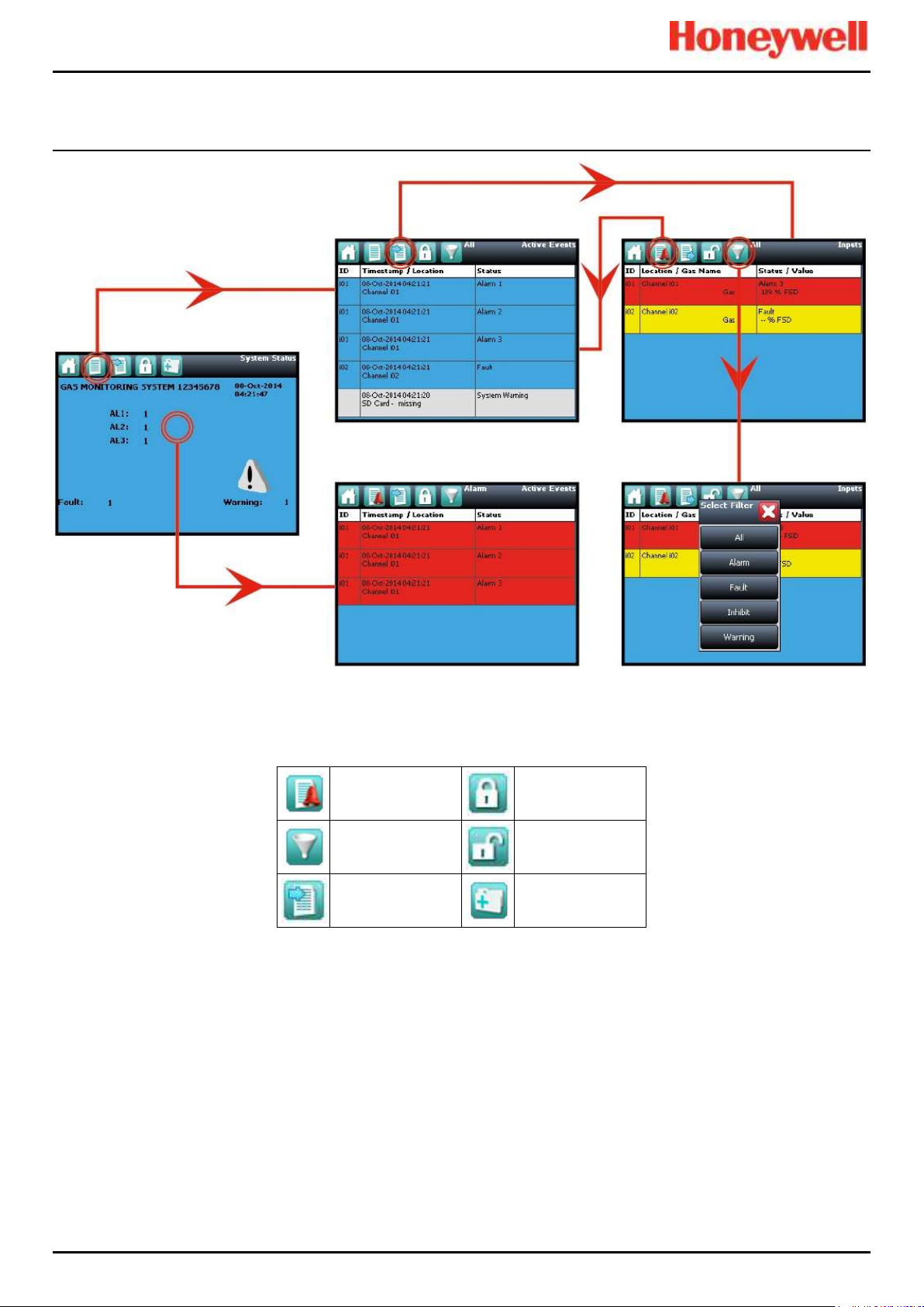
Normal Day-to-Day Operation
Touchpoint Pro
Pt. No. 2400M2566_6_EN 31 Operating Manual
Key
Active Events
Login
Filter Events
User Logged In
Inputs
Tool Box
Figure 33. Touchscreen Navigation – Active Events
Page 41

Normal Day-to-Day Operation
Touchpoint Pro
Pt. No. 2400M2566_6_EN 32 Operating Manual
5.5.5 Login Requirements
To login you must be a registered Administrator, Engineer or Operator and have a valid password.
To login, touch the Login icon (closed padlock) in the navigation bar and enter the User Name and Password. The padlock
will then change to an open padlock, indicating that a user is logged in.
Note: The user will be automatically logged out after 20 minutes of inactivity or if PC Configuration software assumes remote
control. If Touchscreen calibration was in progress you must complete the calibration and log in again before you can
proceed with any other actions.
5.6 How to Recalibrate the Touchscreen
Recalibrate the Touchscreen if it does not respond correctly when touched. This process should take less than a minute but
can only be performed at the Touchscreen.
Calibration must be fully completed once started as there is no option to abort the process.
To recalibrate the Touchscreen:
1. Login as Engineer or Admin
2. Select Tool Box>Global Settings>Panel Configuration>Calibrate Touch Panel
3. Follow the instructions, using a finger or soft stylus to touch each panel corner in turn
4. Finally touch the panel centre to exit
Note: The Fault LED may show if calibration is started but not completed, but will stop when calibration is fully completed.
Note: Screen calibration does not time out even when the backlight or UI times out, and user commands will not be available
until calibration is fully completed. You must complete the Touchscreen calibration first, and then you can carry on with other
activities.
5.7 How to View Input Channels and Input Details
Note: In the Touchscreen view, the Inputs and Outputs icons toggle – from the System Status screen navigation bar only
the Inputs icon is visible, and when you change to the Inputs screen the Outputs icon becomes visible.
1. From the System Status screen navigation bar, select the Inputs icon.
2. A list of all input channels is shown in order of Channel ID. The Channel ID, location tag, gas name, status and
current reading are shown.
3. The list can be filtered by status – Alarm, Fault, Inhibit, Warning or All.
4. Select a channel. Choose one of the options described in the table below.
Option
User Level
Comment
Inhibit
Engineer
Inhibits the channel. On an inhibited channel, this option changes to Clear Inhibit.
Calibration
Engineer
Calibrate the channel.
Trend Graph
All
Shows the trend graph for the channel.
Input Details
All
Shows detailed information about the channel including Custom ID, sensor and gas
name, gas reading, configured alarms and alarm levels.
View Signal
Administrator
Shows the raw signal being received on the channel.
Table 9. Input Channel Menu Options
Page 42

Normal Day-to-Day Operation
Touchpoint Pro
Pt. No. 2400M2566_6_EN 33 Operating Manual
Figure 34. Input Details Screen
5.8 How to View Output Channels
In the Touchscreen view, the Inputs and Outputs icons toggle – from the System Status screen navigation bar only the
Inputs icon is visible; selecting the Inputs icon makes the Outputs icon visible.
1. From the System Status screen navigation bar, select the Inputs icon and then the Outputs icon.
2. A list of all output channels is shown in order of Channel ID with its location tag and status as shown below:
Figure 35. Outputs Screen
3. Select the Filter icon to filter by status – Fault, Inhibit, Warning or All, as shown below:
Figure 36. Outputs Screen with filter options
4. Select a channel. Depending on your access level, a number of options may be shown:
Page 43

Normal Day-to-Day Operation
Touchpoint Pro
Pt. No. 2400M2566_6_EN 34 Operating Manual
Function
User Level
Comment
Inhibit
Engineer
Use this option to Inhibit the channel. Once selected this option changes to Clear Inhibit.
Force
Engineer
Use this option to Force a relay output channel to its active state. Once selected this
option changes to Clear Force. See Ch. 12.3 and 12.4 for more information. The channel
status changes to Fault.
Force
Deactivate
Engineer
Use this option to Force a relay output channel to its deactivated state. Once selected this
option changes to Clear Force. See Ch. 12.3 and 12.4 for more information. The channel
status changes to Fault.
Table 10. Inhibit / Force Options
5.9 How to View the Trend Graph
The trend graph shows the history of the signal on an analog input channel. The signal value is logged when it changes, or
every one hour if there is no change.
Note: TPPR does not adjust automatically for daylight savings time. Be aware that if the date and time are changed to a time
in the past, (for example ending daylight savings time) TPPR will retain a backup of the previous data.
Note: TPPR logs the trend data point when the system is in Field Inputs Test Mode, but does not log it when in the
Configuration Settings Test or Cause and Effect Test modes.
Note: The system logs when the value changes, with a resolution determined by the gas range of the channel. For a gas
range of less than 10, the resolution is 0.01, for a gas range of 10 to 99 the resolution is 0.1, and for a gas range of 100 or
more, the resolution is 1.
Note: The display may not show negative values. If negative values are suspected, due to zero drift or an input fault, use the
Trend Graph Settings icon to offset the Y axis zero.
5.9.1 To View the Trend Graph
1. From the System Status screen navigation bar, select the Inputs icon.
2. A list of all input channels is shown in order of Channel ID.
3. Select the required channel, and select Trend Graph from the popup menu.
4. The trend graph will be displayed.
5. Use the forward and backward arrows to scroll through the graph. Expand or reduce the axes using the X+, X-, Y+
and Y- buttons.
If there are more data points than the number of pixels available on the screen, TPPR will display the maximum value within
each set of points. This is the MaxLine. (For example, if one pixel needs to represent 12 seconds, it will display the
maximum value that occurred during those 12 seconds.) If you toggle to MinLine, TPPR will display the minimum value
within each set of points.
Note: Webserver (if used) will by default display both MaxLine and MinLine. This can be changed to show only MaxLine,
only MinLine or both.
Figure 37. Trend Graph Screen
Page 44

Normal Day-to-Day Operation
Touchpoint Pro
Pt. No. 2400M2566_6_EN 35 Operating Manual
5.10 How to View Event History
The event history for the complete system can be viewed in date order (latest first). The history can be filtered by Alarm,
Fault, Inhibit, Warning, All or by selecting a date range.
To access event history, from the System Status screen navigation bar select Tool Box, then Event History or in
Webserver directly select the Event History icon.
Note: The event history time stamp resolution is ± 5 seconds.
Note: TPPR does not adjust automatically for daylight savings time. Be aware that if the date and time are changed to a time
in the past, (for example ending daylight savings time) TPPR will retain a backup of the previous data.
5.11 How to View Event Reports
Several report types can be generated. Reports can be saved to a memory device such as SD or USB, or printed if a printer
is connected and configured, but saved reports cannot be viewed until the memory device is opened in a PC.
You can use the UI filters to generate:
• Trending for a specific channel, date range is selectable
• Channel events for a specific channel, date range is selectable
• Configuration for a specific channel
• All events within a selectable date range
• Calibration Report
• System Configuration Report
5.11.1 How to Generate Reports
The report is generated as a Comma Separated Value (.csv) text file.
Depending on the amount of activity, text files can be excessively long and difficult to interpret when printed so it is advisable
to import the file into a spreadsheet and use the spreadsheet tools to organise the data.
Webserver (if used) can save or automatically open the report in Microsoft Excel or in a text editor.
Microsoft Excel 2003 is limited to a maximum of 65,526 entries so, if the report is too large, a ‘File not loaded completely’
message may be generated. Microsoft Excel 2010 has no such restriction.
To generate a report:
1. From the System Status screen navigation bar select Tool Box, then Report
2. Select the type of report required (see section above), and if applicable select the channel required
3. Select required start and end dates and times
4. Select Save or Print as required
Note: The Save/Print option is disabled until a channel is selected.
Note: TPPR does not adjust automatically for daylight savings time. Be aware that if the date and time are changed to a time
in the past, (for example ending daylight savings time) TPPR will retain a backup of the previous data.
5.11.2 How to Print Active Events
Note: To enable printing, ensure the printer is connected to the Ethernet port and a valid TCP/IP address is being used.
To change print settings:
1. Login as an Administrator or Engineer
2. From the System Status screen select the Tool Box icon then Panel Configuration
3. Select Print Active Events
4. Select Enabled or Disabled and then Apply
When enabled, each event will be sent to the printer as it occurs.
Page 45

Normal Day-to-Day Operation
Touchpoint Pro
Pt. No. 2400M2566_6_EN 36 Operating Manual
5.12 How to Access Diagnostic information
Engineer access level is required.
The Diagnostics screen gives information about the firmware versions of system components, and details of the status and
any errors. This information could be required by Honeywell Analytics to assist with technical support. The Diagnostics
screen also provides access to the TPPR system test modes (see TPPR Technical Handbook, Ch.16 How to Test the
TPPR).
To access Diagnostics, from the System Status screen navigation bar select Tool Box, then Diagnostics. The
Diagnostics screen also provides access to a drop-down menu that offers the following tests:
• LED Panel Test
• Field Inputs Test
• Configuration Settings Test
• Cause and Effect Test
• System Relay Test
• Panel Button Test
• LCD Screen Test
Further information can be found in the Touchpoint Pro Technical Handbook.
5.13 Managing the Integral SD Card
TPPR is supplied with a 4 GB Industrial Grade FAT32 SD card installed, although you can replace it with a larger card if
required. Replacement SD cards should be the same industrial standard to ensure longevity and to protect against data loss.
5.13.1 SD Card Purposes
The Controller’s SD Card is used for:
• Ongoing storage of event and trend data
• Storage of locally generated reports
• Storage destination for backup files
• Storing configuration backup files
• Internal system management
The SD card should not normally be removed from the controller. However, if it is necessary to remove the card, the
controller will continue to cache data but the same card should be reinserted as soon as possible. The cached data will be
automatically saved to the card when it is re-inserted.
Under most circumstances the controller can cache several hours of events in internal memory. However, inserting a
replacement card causes the cached data to be flushed to this card, and it will no longer be available in the cache for saving
to the original card.
WARNING
The SD Card is located inside the TPPR Controller’s enclosure. Always ensure that the local atmosphere is safe
before opening the enclosure..
It is not necessary to ‘power off’ when removing/inserting an SD Card but
do not touch any exposed terminals or wiring.
Page 46

Normal Day-to-Day Operation
Touchpoint Pro
Pt. No. 2400M2566_6_EN 37 Operating Manual
5.13.2 SD Card Management
The SD card should not normally be removed from the controller. If it is necessary to remove the SD card the controller will
continue to cache event and trend data until the SD card is re-inserted.
The following points should be noted:
• The controller will not accept an SD card containing data for another TPPR system.
• Take care to re-insert the correct SD card, or a permanent replacement. The controller will flush cached data to the
SD card when a card is re-inserted. It a different SD card is fitted data will become fragmented and may not be
useable.
• Similarly, when an SD card has been replaced, the original SD card should not be re-fitted for the same reason.
• The TPPR will continue to operate normally with no SD card fitted. The controller can cache several hours of events
in internal memory. When the cache is full the oldest data is overwritten and cannot be recovered.
• The TPPR will continue to operate normally with a full SD Card. When the card is full the oldest data will be
overwritten. The overwritten event and trend data cannot be recovered.
• The TPPR will warn when the SD card is 80% full, when the card is full, and when previous data is being overwritten
5.13.3 SD Capacity Reporting
The TPPR will warn when the SD card is 80% full and warn again when the card is full, and will warn yet again when
previous data is being overwritten.
The TPPR will continue to operate normally with a full SD Card but overwritten event and trend data will be irrecoverable.
5.13.4 How to Check the SD Card Capacity
From the System Status screen navigation bar, select Tool Box>SD Card to show the card’s capacity and unused space.
5.13.5 Ejecting the SD Card
Event and trend data is held in system memory and saved to the SD card several times per minute.
To ensure that chronology is correctly maintained, and to minimise loss of event history data during updates, always use the
‘Eject SD Card’ command before removing the SD Card from the TPPR, and subsequently reinsert the same or a
permanent replacement card in the system as soon as possible. When the command ‘Eject SD Card’ is used, the data
currently held in system memory is immediately downloaded to the SD Card.
5.13.6 Replacing an SD Card
Before replacing an SD card, event and trend data should be exported to report files, using the Touchscreen or the
Webserver as the source files cannot be read by commercial office software. See the TPPR Technical Handbook,
Ch.13.12 How to View Event Reports for further information.
The new card requires no special preparation but should be unlocked and formatted. Prior to installing you may want to use
a card reader to copy the TPPR Configuration directory and recent backup files from the old SD card to the new one.
Note: SD Cards must be formatted to FAT32 only; other file systems are not supported and will not work.
Note: Once an SD card has been replaced the original SD card should not be reinserted in the TPPR. This is because some
event and trend data will be saved to each card and the data will become fragmented.
5.14 Accessing Help
From the System Status screen navigation bar, select Tool Box, then Help. This help screen will show the date of the last
configuration change, configuration version, previous user, about TPPR and the service contact options.
The configuration version increments every time that parameters are written to the TPPR, including during calibration. The
configuration version can also be used as a check against unauthorised modification of the system.
• Select About to view software and firmware versions.
• Select Service Contact for details of how to access technical support.
Page 47

Normal Day-to-Day Operation
Touchpoint Pro
Pt. No. 2400M2566_6_EN 38 Operating Manual
5.15 System State Relays
The Control Module has two System State relays, rated at 30 VDC, 3 A or 250 VAC, 3 A. The contacts are closed in normal
operation and open under the following conditions:
• The System Fault relay is open if one or more of the conditions listed Table 11. is present.
• The System Failure relay is open if one or more of the conditions listed in Table 11. is present.
The System State relays and any other relays configured for safety purposes should be wired to a continuously monitored
system for safe operation. This is to ensure that all system faults are detected promptly and appropriate action taken.
Note: During start-up, the System Failure relay is open until the CCB is available.
Note: The Redundant CCB taking over from a failed Master CCB is not considered to be a system failure, and the System
Failure relay will remain in normal state.
System Failure Relay TB4
System Fault Relay TB5
Major power loss
Display unit internal fault
Fuse blown
Module diagnostics checks reported a fault
Controller software diagnostics failure detected
A channel is in inhibit, Fault or Warning state
Relay Test is being conducted in Test Mode
System is in Test Mode, other than LED and LCD Tests
An output is an a Force or Force Deactivate state
Table 11. System State Relay Operation
5.15.1 ROM Output Relays on System Fail
If a system failure occurs all ROM output relays will de-energise, regardless of their configured states.
5.15.2 AOM Output Relays on System Fail
If a system failure occurs all AOM outputs will output a fault current of <0.5 mA.
Page 48

Alarms, Faults, Warnings and Inhibits
Touchpoint Pro
Pt. No. 2400M2566_6_EN 39 Operating Manual
6 Alarms, Faults, Warnings and Inhibits
TPPR may be set up to monitor many types of alarms in different areas of your site or sites. They may also be set up to
react in different ways, such as:
• 'Latched' or 'Unlatched' alarms
• Short Term and Long Term Exposure Limits (STEL / LTEL) alarms
• Rate Alarm
• Activation of Relay Outputs
• Voting / Non-voting alarms
• Digital Inputs configured as alarms
6.1 Latching Alarms
During TPPR manufacture of Configuration the alarm channels will have been set as Latched or Unlatched. The default is
usually Latched, but this can be changed if required.
Unlatched alarms self-reset once the hazard has cleared, while latched alarms require the user to verify that conditions are
safe/normal before manually resetting the alarm.
The STEL alarm can be configured as latching or non-latching. STEL alarms should normally be set to latched to capture the
event until it is acknowledged.
The STEL alarm can only be reset when TPPR has calculated that the average gas level over the STEL Time Interval has
fallen below the STEL Alarm Level. Therefore, it will take a certain time before the STEL alarm can be reset even though
there may no longer be gas present. The length of time before reset is possible depends upon the historic and current gas
concentration/time relationship. If set to non-latching, the STEL alarm indication will persist until the average gas level over
the STEL Time Interval has fallen below the STEL Alarm Level. See the next section for more detail.
6.2 STEL / LTEL Alarms
Short Term Exposure Limits (STEL) and Long Term Exposure Limits are the toxic limits that the human body can tolerate
without suffering acute or chronic distress, injury, illness or disease. These figures will vary with every chemical or gas, and
they may vary again as more advanced and long-term laboratory testing produces new results.
TPPR uses analog gas sensors to detect and record ambient toxic gas concentrations for STEL/LTEL. These readings have
two functions: firstly a rise in gas concentration above a pre-set STEL base rate will trigger the STEL alarm and secondly a
prolonged gas concentration above a pre-set LTEL base rate averaged over a period of time will trigger the LTEL alarm.
TPPR averages STEL gas levels every ½ minute over user-determined rolling periods ranging from 5 to 60 minutes and, for
LTEL, continuously rolling periods of 10 minutes fixed at 8-hours total; i.e. 8 hours being the standard shift length.
Full details of STEL/LTEL theory and limitations are given in the TPPR Technical Handbook, Ch.10 Configuring STEL and
LTEL Alarms. Details on setting it up are given in the TPPR Technical Handbook, Ch.7 Software Setup and Commissioning.
6.2.1 Using the STEL Alarm
Use the short term exposure limit (STEL) feature to indicate if a gas sensor is detecting an average level of gas that will
result in a hazardous situation.
The STEL feature continuously calculates the average gas level over time using a user selectable time period (STEL Time
Interval). An alarm will be indicated if the average gas level exceeds a user selected limit (STEL Alarm Level) within the
STEL Time Interval.
STEL alarm functionality is normally associated with personal gas detection equipment where it will give information about
an individual’s exposure to a hazard. As TPPR and associated sensors are fixed equipment, the user must consider how the
STEL feature is to be used as it is the sensor and not an individual that is exposed to gas.
CAUTION
In some countries, the use of a STEL alarm with fixed gas detection equipment is not recommended.
Refer to local and national regulations for further information.
Page 49

Alarms, Faults, Warnings and Inhibits
Touchpoint Pro
Pt. No. 2400M2566_6_EN 40 Operating Manual
The STEL function becomes active and starts monitoring the average gas level when the STEL alarm has been enabled and
the input module returns to its normal state. If the STEL alarm had already been enabled prior to TPPR being powered
down, then the STEL function becomes active when TPPR is powered up.
6.2.2 Assigning the STEL Alarm to an Output Relay
To assign an output relay to an input channel’s STEL alarm, navigate to the cause and effect (C&E) matrix for the required
relay and select Alarm 1 (AL1) for the input channel as shown in the figure below.
Threshold Alarm 1 and STEL share the output relay. If the channel is programmed for threshold levels then AL1 selection is
used for the first threshold alarm and STEL may not be assigned to a relay. Similarly, if the channel is programmed for
STEL, AL1 is reserved for STEL and may not be assigned to a threshold alarm.
This relay will also be assigned to the required inputs for Threshold alarm 1.
ID/Location
AL1
AL2
AL3
FLT
INH
WRN
Select All
133 – 1 mA Ch1
6.3 Rate Alarm
Rate Alarms can be setup to trigger when a gas concentration changes quickly. An alarm may be triggered by a rising or
falling gas level even though the gas has not reached a threshold level. The extent of change and the time period are
programmable.
6.4 Relay Activated Outputs
TPPR has the ability to automatically operate relay controlled outputs when an alarm is triggered. These outputs are
determined during commissioning and may be used to control any or all of these:
• Light Stacks and Sirens
• Automated Emergency Services alerts
• Actuator controlled vents, valves and switches (i.e. power-breaking, purging, sprinkling or flooding)
• Exit door release
• Entry Barrier closing
6.5 Sensor Over Range Operation
TPPR can display a warning if an input signal exceeds the configured gas range. Two signals are provided:
• Full Scale Exceeded
• Over Range Warning
The Full Scale Exceeded warning is displayed, if enabled, when the gas reading exceeds the programmed range. The
warning is cleared automatically when the signal returns below 100% of the selected range.
The Over Range Warning is programmable. If enabled, the warning is displayed when the gas reading exceeds the
programmed level (default is 110% of the programmed range).
Select AL1 to assign this relay to the selected inputs STEL alarm. Note that this relay will
also be assigned to the selected inputs alarm 1 threshold.
WARNING
The Over Range Warning must be configured to Latching to ensure compliance with EN60079-29-1.
Page 50

Alarms, Faults, Warnings and Inhibits
Touchpoint Pro
Pt. No. 2400M2566_6_EN 41 Operating Manual
The Over Range Warning has a higher priority than the Full Scale Exceeded warning. If the Over Range Warning is
asserted, the Full Scale Exceeded warning is cleared.
6.5.1 Gas Readings
The maximum gas readings experienced may be seen by viewing the Trend graph.
6.6 Catalytic Sensor Over Range Operation
The reading from a catalytic sensor can return to a false low if the gas level exceeds the sensor operating range. The
latched Over Range Warning indicates that an exceptionally high gas level has been detected and further investigation is
required.
The Over Range Warning requires an extra Reset operation to clear. The first Reset clears the over range warning, the
second reset clears any other conditions, provided that gas readings have returned to suitably low levels.
The Over Range Warning is available on mV channels (default: enabled) and on mA channels (default: disabled) for use
with catalytic sensors connected via a mA transmitter.
6.7 Full Scale Exceeded and Over Range Warning Operation
The following two examples show the detailed operation of the Full Scale Exceeded and Over Range Warning warnings.
Note: For clarity alarms (AL1, AL2, AL3) and other conditions are not shown.
Pre-conditions:
• Full Scale Exceeded is enabled and set to 100% of the pre-set gas range
• Over Range Warning is enabled and set to 120% of the pre-set gas range (Latched)
WARNING
The Over Range Warning parameter must be configured to 100 %FSD to ensure compliance with EN60079-29-1.
Page 51

Alarms, Faults, Warnings and Inhibits
Touchpoint Pro
Pt. No. 2400M2566_6_EN 42 Operating Manual
6.7.1 Event Status with a Rising Gas Reading
Rising Gas Reading
Event Status
(Full scale/Over
Range)
Event History
(Sequential Entries)
Remarks
Below 100%
—
—
—
≥100% & <120%
Full Scale Exceeded
Active
Full Scale Exceeded Active
—
≥120%
Over Range Warning
Active
Full Scale Exceeded Active
Full Scale Exceeded Cleared
Over Range Active
Full Scale Exceeded autocleared (overwritten by Over
Range Warning)
Table 12. Rising Gas Reading
6.7.2 Event Status as the Gas Concentration Decreases
The indicated value remains at the programmed Over Range Warning value. A "greater than" symbol (">") is displayed to
indicate that the programmed level has been exceeded. The latched reading may be reset once the gas concentration has
decreased below the programmed level.
The Over Range Warning remains Latched.
Note: In the following example, Full Scale Exceeded will not reappear until the gas concentration falls to between 100% &
120% of the pre-set gas range and the latched Over Range Warning has been reset manually.
Falling Gas Concentration
Event Status (Full
Scale/Over Range)
Event History
(Sequential Entries)
Remarks
≥100% & <120%
Over Range Warning
still Active (latched)
Full Scale Exceeded Active
Full Scale Exceeded Cleared
Over Range Active
Full Scale Exceeded is hidden
while Over Range Warning is
active.
≥100% & <120%
Full Scale Exceeded
Full Scale Exceeded Active
Full Scale Exceeded Cleared
Over Range Active
Over Range Cleared
Full Scale Exceeded Active
1st manual reset attempted by
user.
Over Range Warning reset
was successfully.
Full Scale Exceeded may
appear.
Below 100%
—
Full Scale Exceeded Active
Full Scale Exceeded Cleared
Over Range Active
Over Range Cleared
Full Scale Exceeded Active
Full Scale Exceeded cleared
The 2nd manual reset can be
applied now and Full Scale
Exceeded should auto-clear.
Table 13. Falling Gas Reading
WARNING
A potentially explosive gas concentration may still exist at this point.
Page 52
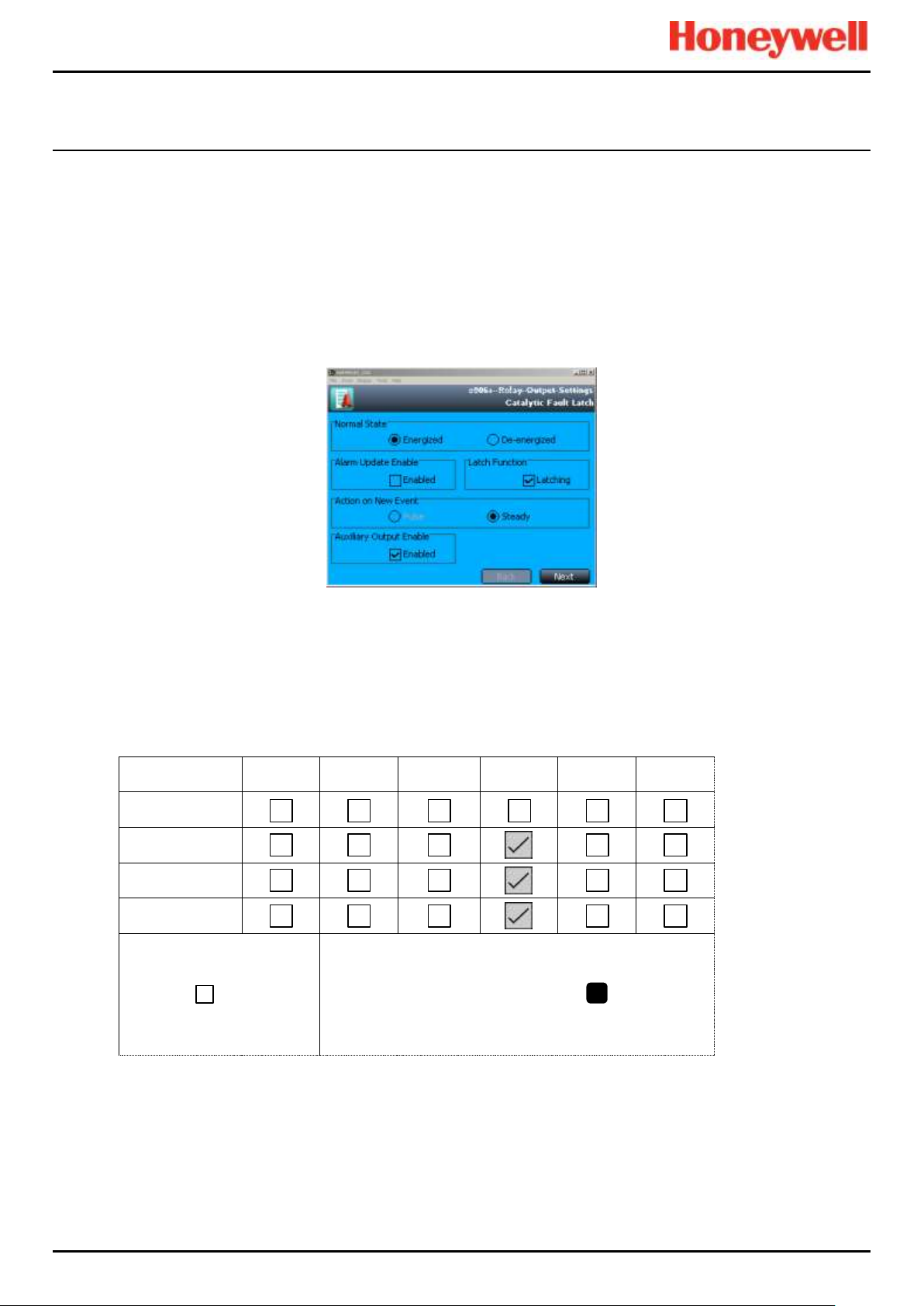
Alarms, Faults, Warnings and Inhibits
Touchpoint Pro
Pt. No. 2400M2566_6_EN 43 Operating Manual
6.7.3 Special Considerations when using Catalytic Sensors
Touchpoint Pro continually carries out diagnostics to prove that the system is operating correctly and faults such as wiring
faults will clear automatically when the system detects that the fault has been corrected.
In rare circumstances (due to insufficient oxygen for the sensor to operate correctly) a high gas concentration could occur
while the system is in fault, and which may not be detected by the system due to the fault. It is therefore highly
recommended to configure at least one Relay Output to latch on fault on channels that are used with catalytic sensors.
6.7.4 Configuration of Relay Outputs
Each output must be configured as Normally Energized, Alarm Update Enable not selected, and Latch Function selected, as
shown in the following example:
Figure 38. Fault Latch Output Configuration
Auxiliary Output Enable should normally be selected if any load is connected to the module auxiliary output supplies (e.g. a
sounder or a beacon). A fault will then be generated if the output current limit is exceeded.
Each output must be configured as Output Type Normal, with a cause and effect matrix similar to the following example.
The cause and effect matrix must include all channels using catalytic sensors, in this instance three mV channels.
ID/Location
AL1
AL2
AL3
FLT
INH
WRN
Select All
mV Channel 1
mV Channel 2
mV Channel 3
At least One Alarm
Enabled
Vote Count
Channels Selected:
3
To allow zoning of sensors it is possible to assign as many or as few input channels to the relay output channels as required,
however it is a requirement of the European Performance Approval that at least one channel is configured to latch such a
fault.
1
Page 53

Alarms, Faults, Warnings and Inhibits
Touchpoint Pro
Pt. No. 2400M2566_6_EN 44 Operating Manual
6.8 Responding to Alarms, Faults and Warnings
Users may respond to alarms and other events by various methods.
All users may view events, as described below.
Events may be acknowledged or reset by various methods, including the controller front panel Accept and Reset buttons,
touch screen menus, remote DIM-controlled switches, and, if enabled, Webserver and Modbus.
Access to controller Accept and Reset functions may be restricted to logged in users. The system may be configured so
that the Accept and Reset buttons are password protected and require a user to login. Refer to the TPPR Technical
Handbook for further information.
Note: Switches and buttons connected to DIM channels may be used to provide remote Accept, Reset and Inhibit
functions. These inputs cannot be password controlled so it is the user’s responsibility to limit access, if required, by using
other methods such as key operated switches. Refer to the TPPR Technical Handbook for further information.
Note: Alarms may be commissioned as 'Latched' or 'Unlatched'. Unlatched alarms self-reset once the hazard has cleared,
while latched alarms require the user to verify that conditions are safe/normal before manually resetting the alarm.
WARNING
Over range gas alarms should be investigated before attempts are made to reset them.
WARNING
High ‘off-scale’ readings may indicate an explosive concentration.
AVERTISSEMENT
Des résultats dépassant considérablement l’échelle peuvent être indicateurs d’une
concentration explosive.
Page 54

Alarms, Faults, Warnings and Inhibits
Touchpoint Pro
Pt. No. 2400M2566_6_EN 45 Operating Manual
6.8.1 To View Active Alarms
Active alarms can be viewed in three ways:
• From the System Status (Home) screen, select the flashing red bell Alarm icon.
• From the System Status (Home) screen navigation bar, select the Active Events icon, then the Filter icon and then
select Alarm from the popup menu.
• From the System Status screen navigation bar, select the Inputs icon, then the Filter icon and select Alarm from the
popup menu.
The screen will display a list of all the input channels that have active alarms, starting with the most recent event.
Unacknowledged alarms will flash, acknowledged ones will not flash.
Note: The display shows the channel ID, location tag and the time of the alarm. All alarm levels will be shown if more than
one alarm level has been triggered on the same channel.
Figure 39. Active Events Screen with Filter Options
6.8.2 To Acknowledge an Active Alarm
An active alarm can be acknowledged from the controller in three ways:
• Select the Accept button on the front panel of the TPPR Controller for >0.5 s. This will acknowledge all active
events, including faults and warnings.
• From the Inputs screen, select the channel and select Acknowledge from the popup menu. This will acknowledge all
active events for that channel only.
• From the Active Events screen, select the alarm and select Acknowledge from the popup menu. This will
acknowledge only the selected alarm.
Acknowledging an alarm silences the buzzer and the alarm icon stops flashing, but latched alarms are not automatically
reset.
Note: The Alarm Update function modifies the operation of Output channels when events are acknowledged. Refer to the
TPPR Technical Handbook.
Page 55
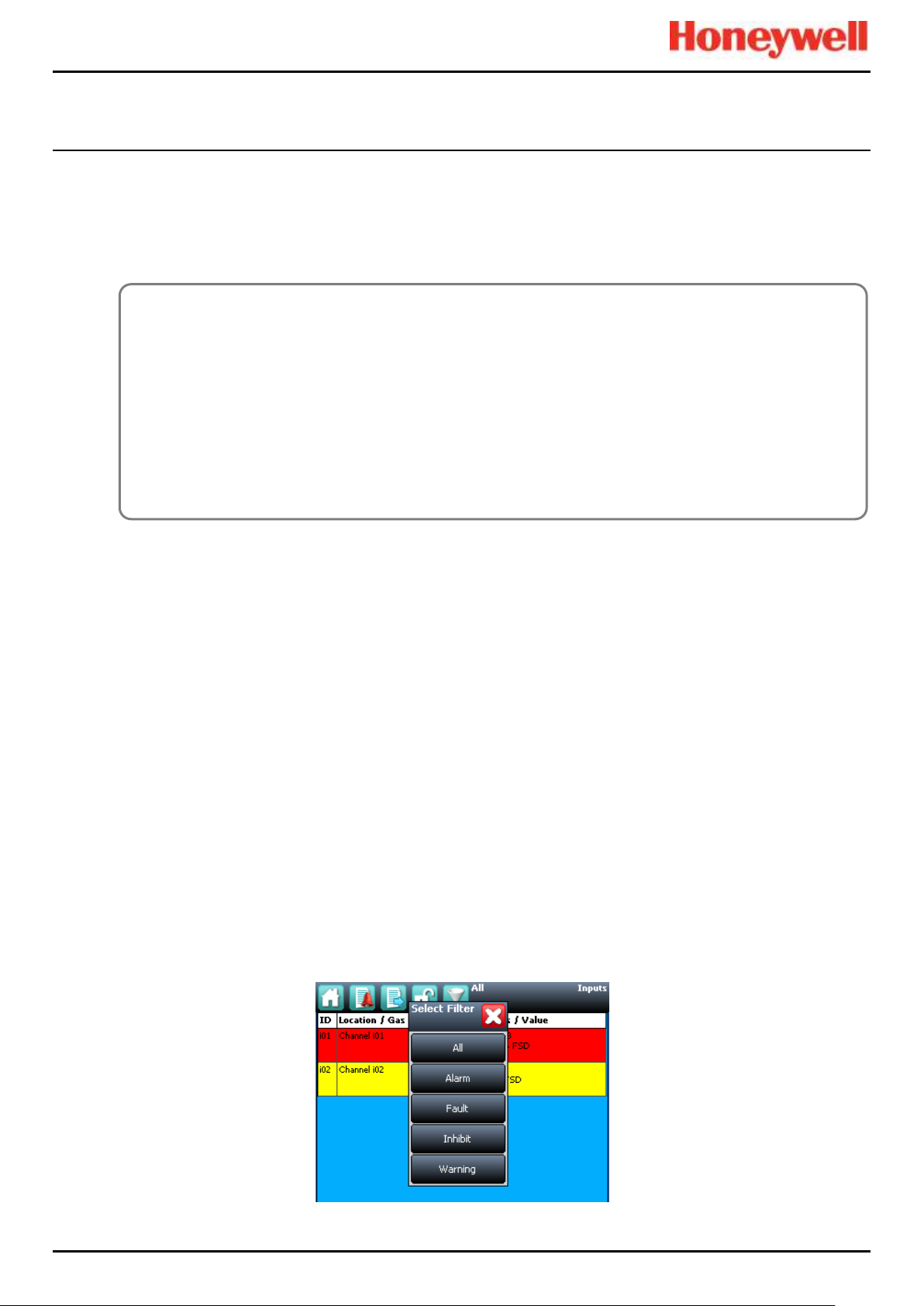
Alarms, Faults, Warnings and Inhibits
Touchpoint Pro
Pt. No. 2400M2566_6_EN 46 Operating Manual
6.8.3 To Reset a Latched Alarm
Alarms may only be reset if the event causing the alarm has been cleared; typically when the reported gas level has fallen
below the alarm threshold.
If the Over Range Warning signal is latched, two Reset operations are required. The first Reset clears the Over Range
Warning, the second Reset clears any other conditions.
A latched alarm can be reset in three ways:
1. Select the Reset button on the front panel of the TPPR for >0.5 s. This will reset ALL latched alarms, faults and
warnings, provided that the event has cleared. It will also reset any latched relay outputs.
2. From the Inputs screen, select the channel and select Reset from the popup menu. This will reset all latched events
for the channel, provided that the input signal has returned to below the alarm threshold status.
3. From the Active Events screen, select the alarm and select Reset from the popup menu. This will reset only the
selected alarm.
6.9 Viewing Faults and Warnings
The Active Events screen lists the current event history in the order that the events occurred. TPPR has the option to filter
the history into categories, as shown in the descriptions and picture below.
Events are colour-coded for easier recognition; Red Alarm, Yellow Fault, Orange Inhibit, Grey Warning.
Faults and warnings may only be reset if the reported event has been cleared, for instance the fault has been rectified.
6.9.1 To View Faults and Warnings
Detailed information about active Faults and Warnings can be viewed in two ways:
From the System Status screen, select either the Fault yellow triangle icon, or the Warning grey triangle icon. The screen
will show a filtered list of only the active Faults or Warnings.
Select the Active Events icon to show all active events, then the Filter icon and select Fault or Warning from the popup
menu.
Figure 40. Active Events Screen Showing the Filter Option Buttons
CAUTION
The TPPR system is designed to alert the user to potentially dangerous events and to trigger protective measures.
It is the User's responsibility to ensure that the site emergency response procedures are initiated before accepting
alarms, and that the danger has been investigated and cleared before resetting the alarms.
Alarms cannot be reset until the gas concentration is below the threshold limits.
An STEL Alarm cannot be reset if the current value of the time weighted average (TWA) is above the pre-set alarm
threshold.
An LTEL Alarm cannot be reset if the current gas reading is above the pre-set alarm threshold.
Page 56

Alarms, Faults, Warnings and Inhibits
Touchpoint Pro
Pt. No. 2400M2566_6_EN 47 Operating Manual
6.9.2 To Acknowledge (Accept) a Fault or Warning
Operator or higher access level may be required.
An active fault or warning can be acknowledged in three ways:
Select the Accept button on the front panel. This will acknowledge ALL active events.
From the Inputs or Outputs screen select the individual channel and select Acknowledge from the popup menu. This will
acknowledge all active events for the channel.
From the Active Events screen, select the fault or warning and select Acknowledge from the popup menu. This will
acknowledge only the selected fault or warning.
The channel, LED and icon will stop flashing when a fault or warning is acknowledged.
Note: The Accept button must be pressed for at least 0.5 seconds.
6.9.3 To Reset a Latched Fault or Warning
Operator or higher access level may be required.
A latched fault or warning can be reset in three ways:
• Press the Reset button on the front panel. This will reset ALL latched alarms, faults and warnings, provided that the
event has cleared. It will also reset any latched relay outputs.
• From the Inputs or Outputs screen, select the channel and select Reset from the popup menu. This will reset all
latched events for the channel, provided that the input signal has returned to Normal status.
• From the Active Events screen, select the fault or warning and select Reset from the popup menu. This will reset
only the selected fault or warning.
Note: The Reset button must be pressed for at least 0.5 seconds.
6.10 Inhibiting a Channel
Engineer or Administrator access level is required.
If a channel is in Alarm, inhibiting the input will clear the alarm status for that channel. Inhibiting an output associated with
that channel will deactivate that output, but the input will remain in alarm state. The alarm will continue to be reported on the
controller and may affect other outputs in the cause and effect matrix.
Note: Channels may be inhibited automatically by the TPPR. See next page for more information.
6.10.1 How to Inhibit a Channel
Both input and output channels can be inhibited.
1. From the System Status screen navigation bar, select the Inputs icon and, if appropriate, the Outputs icon.
2. Select the required channel and select Inhibit from the popup menu.
3. To clear inhibits, select the required channel and select Clear Inhibit from the popup menu.
Page 57

Alarms, Faults, Warnings and Inhibits
Touchpoint Pro
Pt. No. 2400M2566_6_EN 48 Operating Manual
6.10.2 Channel Auto-Inhibits
Auto-inhibits may occur when a mV input channel has been configured but not yet calibrated, when a transmitter is signalling
Inhibit, or when an Inhibit delay time is running. Refer to the TPPR Technical Handbook, Ch.17 System Troubleshooting for
further information.
Auto-inhibits cannot be cleared manually.
Figure 41. Inputs Screen with menu options
CAUTION
It is possible to have more than one inhibit condition active on a channel, and you have to resolve all inhibit
conditions before the inhibit can be cleared.
Page 58

Maintenance Procedures
Touchpoint Pro
Pt. No. 2400M2566_6_EN 49 Operating Manual
7 Maintenance Procedures
This chapter describes how to perform common maintenance operations.
The required frequency of inspection and maintenance will depend on local site conditions and will need to be established
through experience. Refer to the following standards or other local or national regulations for guidance on establishing an
appropriate maintenance routine:
EN 45544-4 contains information on the use and maintenance of electrical apparatus used for the direct detection and direct
concentration measurement of toxic gases and vapours.
EN 60079-29-2 is a guide to, and recommended practice for, the selection, installation, safe use and maintenance of
electrically operated group II apparatus intended for use in industrial and commercial safety applications for the detection
and measurement of flammable gases.
Note: When finished, ensure that all enclosures are closed and locked, and ensure that the maintenance and rectification is
recorded.
7.1 Routine Maintenance
Routinely (i.e. daily, weekly or monthly depending on local conditions) carry out the following tasks:
• Clean the Touchscreen with a soft cloth and mild detergent, or use a proprietary VDU screen cleaner.
• Check the screen for correct operation
• Remove dust and other contamination (particularly on rack mounted units or enclosure vents).
• Periodically exercise the relays to confirm functionality (see the TPPR Technical Handbook, Ch.16 How to Test the
TPPR System).
• Check that the SD Card still has free space.
• Check the condition of the enclosure for security, corrosion, deterioration of door seals, blocked ventilation, loose
fixings and other damage that could impair the safety and operation of the equipment or its safety function.
WARNING
If the relays are switching mains voltages, hazardous live terminals may be present within the Relay Output Module
even if the Touchpoint Pro system is isolated.
WARNING
To avoid any unwanted activation of output devices (e.g. emergency flooding) always inhibit or disable relay
activated outputs before exercising the relays and remember to enable them when testing is finished.
CAUTION
Do not use solvents or abrasives to clean any part of the TPPR as this may cause irreparable damage.
WARNING
Maintenance procedures should only be carried out by Honeywell authorised persons or qualified persons trained in
accordance with the Touchpoint Pro Technical Handbook as errors can adversely affect system functions.
Page 59

Maintenance Procedures
Touchpoint Pro
Pt. No. 2400M2566_6_EN 50 Operating Manual
7.2 Periodic Maintenance
Periodic inspection and cleaning should be carried out weekly, monthly or 6-monthly as necessary.
Refer also to the recommended periodic system tests described in Chapter 8 How to Test the TPPR System.
7.2.1 Battery Enclosure Maintenance
Open the battery enclosure (if fitted) and:
• Visually inspect the Touchpoint Pro Battery Box, batteries and all exposed cabling, particularly for signs of corrosion.
• Check the batteries for physical security, cable damage, or loose connections.
• Check that the enclosure vents have not become obstructed. Remove debris with a vacuum cleaner nozzle, taking
care not to disturb wiring or short the terminals.
Close and secure the door when finished.
7.2.2 Cable Maintenance
Additionally, especially following ground maintenance or severe weather:
• Visually inspect all cabling and trunking, checking for signs of damage, perishing or loose connections.
CAUTION
The sealed batteries contain lead and acid. Treat all damaged batteries and leaks as hazardous spills, and dispose
of the battery and contents as hazardous waste.
Page 60

How to Test the TPPR System
Touchpoint Pro
Pt. No. 2400M2566_6_EN 51 Operating Manual
8 How to Test the TPPR System
8.1 Introduction
The TPPR system has the following test modes, which together enable a comprehensive test of the system:
1. LED Panel Test – tests that all of the panel LEDs are working.
2. Field Inputs Test – tests all input channel devices without affecting any outputs. Gas test, force mA, confirmation of
correct device connection etc.
3. Configuration Settings Test – forces the TPPR input channels to specific levels and shows the corresponding
states, threshold alarm levels, over-range, warning/fault etc.
4. Cause and Effect Test (carried out from the output channel menu) – forces the TPPR input channels to specific
states to test that the correct output channels are activated.
5. Panel Button Test – tests that the panel buttons are working
6. System Relay Test – tests that the System Failure relay and System Fault relays are working
7. LCD Screen Test – provides a visual check of the LCD screen
8. AOM Test (carried out from the AOM Test Mode screen) – forces the outputs to specified signal value.
Note: It is recommended that the audio / visual functionality of the system (test modes 1, 5 and 7) are tested annually. Test
modes 2, 3 and 4 should be run as a part of commissioning or after any modification to the system which changes the
system setup.
It is recommended that the system relays (test mode 6) and the Relay Output Module (Force) relays are tested at least every
five years.
When a test mode is active the System Fault relay will normally open and a Test Mode Fault will be shown as an Active
Event on the User Interface, which cannot be reset. The exceptions are the LED Panel Test and LCD screen, which do not
indicate a fault.
Once a test mode is active, the system will remain in test mode until the test is exited. The only exception is in the case of a
power cycle of the TPPR, when it will restart in normal mode.
Note: After 20 minutes of inactivity the system will logout and return to the System Status screen. However it is still running
in test mode and you will need to login to complete the tests.
The optional PC Configuration Software cannot be used while a test mode is active.
All events generated while the system is in test mode will be logged in the event history. Therefore a test record can be
generated once testing is completed (see the TPPR Technical Handbook, Ch. 7.6 How to Print Active Events).
WARNING
During the Cause and Effect Test, outputs will be generated and relays will be activated. To avoid any unwanted
activation of output devices (e.g. emergency flooding) always inhibit or disable relay activated outputs before starting
and enable them when testing is finished.
WARNING
While in test mode, the TPPR is not operational as a safety system and any field device inputs may be ignored. The
System Fault relay may open and the System Failure relay will remain in the current state. Always put alternative
safety arrangements in place before carrying out these tests.
Page 61

How to Test the TPPR System
Touchpoint Pro
Pt. No. 2400M2566_6_EN 52 Operating Manual
8.2 LED Panel Test
Engineer access level is required.
The purpose of this test is to check that the LEDs on the panel are working correctly. This test does not indicate a Fault
while in progress.
How to use the LED Panel Test mode:
9. Login as an Engineer.
10. From the System Status screen select the Tool Box icon:
11. Select Diagnostics.
12. Select the Menu icon:
13. Select LED Panel Test.
14. The system will ask you to confirm, select OK to proceed.
15. The system will illuminate all LEDs and then cycle through the LEDs turning each one on in turn.
Note: The green power LED will remain illuminated throughout if it is working correctly.
16. At the end of the test the system will ask you to confirm the LED test passed.
8.3 Field Inputs Test
Engineer access level is required.
During this test, all field device inputs will be displayed, but the Cause and Effect matrix will not be evaluated. No outputs
will be generated.
The purpose of this test is to check that the input field devices are connected to the correct input channel. Typically, this can
be done either by applying a test gas to the sensor in the field or by forcing the mA output of the sensor to a given value.
The gas concentration and alarm states raised for the channel can then be viewed on the Touchscreen UI or PC GUI. The
system fault relay will be open.
How to use the Field Inputs Test mode:
1. Login as an Engineer.
2. From the System Status screen select the Tool Box icon:
3. Select Diagnostics.
4. Select the Menu icon:
5. Select Field Inputs Test.
6. The system will ask you to confirm, select Yes to proceed.
7. The system will display a confirmation message, click on OK and you will be automatically navigated to the Active
Events screen.
8. Proceed with the test of the field devices. To see more detailed information at any time, select the channel of interest
and select Input Details from the popup menu.
Note: If the test is done from the Active Events screen, the channel of interest will be shown as soon as its state changes,
i.e. a threshold alarm is generated. Alternatively, you may wish to work from the Inputs screen (return to System Status
screen and select Inputs) by scrolling down to the channel you want.
9. When the test is complete, return to the System Status screen and select the Tool Box icon:
10. Select Diagnostics.
11. Select the Menu icon:
12. Select Stop Field Inputs Test.
13. The system will show a confirmation message that it has returned to normal operation.
WARNING
Check and ensure that the system is restored to normal operation once all testing is finished.
Page 62

How to Test the TPPR System
Touchpoint Pro
Pt. No. 2400M2566_6_EN 53 Operating Manual
8.4 Configuration Settings Test
Engineer access level is required.
During this test, all field device inputs will be ignored by the TPPR. The Cause and Effect matrix will not be evaluated. No
outputs will be generated.
The purpose of this test is to check that input channels are configured correctly, including alarm, warning, fault thresholds
etc. The gas concentration and alarm states raised by forcing the input value can be viewed on the TPPR UI or the PC GUI.
The system fault relay will be open.
8.4.1 How to use the Configuration Settings Test Mode
1. Login as an Engineer.
2. From the System Status screen select the Tool Box icon:
3. Select Diagnostics.
4. Select the Menu icon:
5. Select Configuration Settings Test.
6. The system will ask you to confirm; select Yes to proceed.
7. The system will display a confirmation message, click on OK and you will be automatically navigated to the Inputs
screen.
8. Select the channel to be tested and select Input Details from the popup menu.
9. From the Input Details screen, select the Menu icon:
10. Select Force Value.
11. Enter the gas concentration that you want to simulate. This can include over and under range values.
12. The system will return to the Input Details screen, where it will show the simulated gas value as well as
any corresponding active events (e.g. Alarm 1).
13. When ready, select the Menu icon:
14. Select Clear Force.
15. Repeat steps 9 – 14 as required, completing the channel tests.
16. Return to the Inputs screen and repeat steps 8 – 14 for the next channel.
17. When the test is complete, go to the System Status screen and select the Tool Box icon:
18. Select Diagnostics.
19. Select the Menu icon:
20. Select Stop Configuration Settings Test.
21. The system will show a confirmation message that it has returned to normal operation.
WARNING
Check and ensure that the system is restored to normal operation once all testing is finished.
Page 63

How to Test the TPPR System
Touchpoint Pro
Pt. No. 2400M2566_6_EN 54 Operating Manual
8.5 Cause and Effect Test
Engineer access level is required.
During this test, all field device inputs will be ignored by the TPPR system. The Cause and Effect matrix will be evaluated
based on simulated input states and outputs will be generated. The system fault relay will be open.
This test has two purposes:
1. To verify that Cause and Effect matrix configuration is correct by forcing the state of the input channels to various
combinations. The activated/de-activated output channels corresponding to the forced state of input channels can be
viewed on the TPPR UI or Webserver (if enabled).
2. To check that the output channels are configured correctly, including delay on/off times etc. By forcing the state of
the output channel to change the corresponding change in the output device state can be viewed on the TPPR UI or
Webserver (if enabled).
8.5.1 How to use the Cause and Effect Test Mode:
1. Login as an Engineer.
2. From the System Status screen select the Tool Box icon:
3. Select Diagnostics.
4. Select the Menu icon:
5. Select Cause and Effect Test.
6. The system will ask you to confirm, select Yes to proceed.
7. The system will display a confirmation message, click on OK and you will be automatically navigated to the Outputs
screen.
8. Select the channel to be tested and select Output Details from the popup menu.
9. Select the Menu icon:
10. Select Force Input States to do a full test of the Cause and Effect matrix (test purpose1 described above).
11. The system will display a matrix of all the input channels that are linked to the output channel being tested.
12. Select the input channel states that you want to simulate, and click on Force. The cells corresponding to the forced
states will be coloured.
13. The system will return to the Outputs screen where the results of the forced input states can be viewed.
14. When ready, return to the Output Details screen and select the Menu icon:
15. Select Clear Force.
16. Repeat steps 8 – 15 for the next channel.
17. To force the output relays (test purpose 2, described above) select the channel to be tested and select Output
Details from the popup menu.
18. Select the Menu icon and select Force from the popup menu. The output will now be activated and the result can be
verified.
19. When ready, select the channel again, and select Clear Force.
20. Repeat steps 17 – 19 for the next channel.
21. When the test is complete, go to the System Status screen and select the Tool Box icon then Diagnostics.
22. Select the Menu icon:
23. Select Stop Cause and Effect Test.
24. The system will show a confirmation message that it has returned to normal operation.
WARNING
During the Cause and Effect Test, outputs will be generated and relays will be activated. To avoid any unwanted
activation of output devices (e.g. emergency flooding) always inhibit or disable relay activated outputs before starting
and remember to enable them when testing is finished.
WARNING
Check and ensure that the system is restored to normal operation once all testing is finished.
Page 64

How to Test the TPPR System
Touchpoint Pro
Pt. No. 2400M2566_6_EN 55 Operating Manual
8.6 Analog Output Test
Engineer access level is required.
The purpose of this test is to check that the System Failure and System Fault relays are working correctly.
Note: This test may cause higher level systems to generate alarms if connected.
How to use the System Relay Test mode:
1. Login as an Engineer.
2. From the System Status screen select the Tool Box icon:
3. Select Diagnostics.
4. Select the Menu icon:
5. Select Analog Output Test.
6. The system will ask you to confirm, select Yes to proceed.
7. The system will confirm you are in analog output test mode. Press OK to proceed.
8. The system will display analog output channel to select.
9. Select analog output channel to test.
10. Select input event or enter the gas concentration to simulate output.
Note: To exercise gas concentration input event must be in Normal.
11. Select the Menu icon.
12. Select Stop analog output Test.
13. The system will show a confirmation message that it has returned to normal operation.
8.7 Panel Button Test
Engineer access level is required.
The purpose of this test is to check that the buttons on the panel are working correctly.
How to use the Panel Button Test mode:
1. Login as an Engineer.
2. From the System Status screen select the Tool Box icon:
3. Select Diagnostics.
4. Select the Menu icon:
5. Select Panel Button Test.
6. The system will ask you to confirm, select Yes to proceed.
7. The system will confirm you are in panel button test mode. Press OK to proceed.
8. Follow the on-screen prompts to test the panel buttons
9. At the end of the test the system will display the test results
10. Press OK.
11. Select the Menu icon:
12. Select Stop panel Button Test.
13. The system will show a confirmation message that it has returned to normal operation.
Page 65

How to Test the TPPR System
Touchpoint Pro
Pt. No. 2400M2566_6_EN 56 Operating Manual
8.8 System Relay Test
Engineer access level is required.
The purpose of this test is to check that the System Failure and System Fault relays are working correctly.
Note: It may be necessary to disconnect wiring to higher level systems from TB4 (System Failure) and TB5 (System Fault)
on the TPPR controller. This test may cause higher level systems to activate if connected.
How to use the System Relay Test mode:
1. Login as an Engineer.
2. From the System Status screen select the Tool Box icon:
3. Select Diagnostics.
4. Select the Menu icon:
5. Select System Relay Test.
6. The system will ask you to confirm, select Yes to proceed.
7. The system will confirm you are in relay test mode. Press OK to proceed.
8. The system will operate the System Fail relay and ask the user to confirm the monitoring applied by the engineer
has indicated that the relay has been activated (contacts closed).
9. The system will operate the System Fail relay and ask the user to confirm the monitoring applied by the engineer
has indicated that the relay has been deactivated (contacts permanently open with no state switching).
Note: The System Fail relay will be toggling during this test to ensure that no contacts have welded
10. The system will operate the System Fault relay and ask the user to confirm the monitoring applied by the engineer
has indicated that the relay has been activated (contacts closed).
11. The system will operate the System Fault relay and ask the user to confirm the monitoring applied by the engineer
has indicated that the relay has been deactivated (contacts permanently open with no state switching).
Note: The System Fault relay will be toggling during this test to ensure that no contacts have welded.
12. At the end of the test the system will display the test results.
13. Press OK.
14. Select the Menu icon:
15. Select Stop System Relay Test.
16. The system will show a confirmation message that it has returned to normal operation.
17. Reconnect TB4 and TB5 if necessary.
Page 66
How to Test the TPPR System
Touchpoint Pro
Pt. No. 2400M2566_6_EN 57 Operating Manual
8.9 LCD Screen Test
Engineer access level is required.
The purpose of this test is to check that the LCD screen is working correctly. This test does not indicate a Fault while in
progress.
How to use the LCD Screen Test mode:
1. Login as an Engineer.
2. From the System Status screen select the Tool Box icon:
3. Select Diagnostics.
4. Select the Menu icon:
5. Select LCD Screen Test.
6. The system will display a series coloured bars and a progress bar.
7. When the progress bar completes the system asks you to confirm the bars were visible
8. Then select Yes if the bars were visible and No if the screen appears abnormal.
8.10 How to Exercise the Output Relays
To test the Relay output channels by forcing the relays to a specific state:
1. Login as an Engineer. Navigate to the Outputs screen:
a) From the System Status screen select the Inputs icon:
b) Toggle the Inputs Icon to select the Outputs icon:
2. Select the channel to be tested, and then select Force or Force Deactivate, as required. The channel will indicate a
Fault until the action is cancelled.
3. When ready, select the channel again, and select Clear Force from the popup menu.
4. Repeat steps 4 and 5 for all relay output channels.
Note: The system will indicate a fault and the System Fault relay will open while a Force condition is present.
WARNING
To avoid any unwanted activation of output devices (e.g. emergency flooding) always inhibit or disable relay
activated outputs before exercising the relays and remember to enable them when testing is finished.
WARNING
Check and ensure that the system is restored to normal operation once all testing is finished.
CAUTION
To carry out Analog Output Test, refer to Section 16.6 Analog Output Test.
Page 67
Calibrating Gas Sensors
Touchpoint Pro
Pt. No. 2400M2566_6_EN 58 Operating Manual
9 Calibrating Gas Sensors
This section is included for information only. Refer to the Touchpoint Pro Technical Handbook for detailed instructions.
All gas sensors must be calibrated on commissioning, on replacement, at regular intervals specified in their user manuals, or
when dictated by usage. (Touchpoint Pro can be programmed to generate periodic calibration reminders. See the TPPR
Technical Handbook for details.)
Note: Calibration data is not retained following a restore operation and calibration reminders may require updating following
recalibration.
The basic calibration procedure is to first clear the sensor of any target gas and then introduce a known concentration of a
test gas followed by a rest period to ensure that the sensor goes back to normal.
9.1.1 Calibration Definitions
• Clean Air describes ambient air that has a nominal zero concentration of the target gas being sensed.
• First Span is the name given to the first gas span reading of a new mV sensor, which is used to monitor the sensor’s
sensitivity over time.
• An Over Range Warning occurs when a mV sensor exceeds 100 % of Full Scale Deflection (100 %FSD). A gas over
range condition can cause catalytic sensors to operate outside of their working range and incorrectly indicate low gas
concentrations when hazardous concentrations may be present.
• Span gas is a compressed gas containing a specified concentration of the target gas being sensed.
• Span is the gas concentration reading at which calibration is carried out, typically at 50% of full scale.
• Zero Gas describes a test gas that has a zero concentration of the target gas being sensed, and it may be a different
gas for different sensors.
CAUTION
Ensure that executive actions/outputs are inhibited and alternative safety arrangements are made before starting
any TPPR testing or calibration.
CAUTION
It is expected that mA sensors will be calibrated at the sensor or field device. The TPPR mA calibration is not
intended to calibrate the sensor, but to align the TPPR 4-20mA current loop with the sensor current loop zero and
span settings.
The TPPR mA calibration should not be used to calibrate the sensor zero and span, or to compensate for
deficiencies in the sensor or transmitter calibration. Failure to observe this can result in significant accuracy errors.
DANGER
An ‘Over Range Warning’ warning may indicate a rare but potentially catastrophic event that must be fully
investigated. When an Over Range Warning is programmed, TPPR displays a warning on the Touchscreen that
requires an additional Reset operation before the alarm may be cleared.
WARNING
Only Honeywell trained and authorised persons or qualified persons trained in accordance with the Touchpoint Pro
Technical Handbook should carry out Calibration procedures as errors can adversely affect system functions.
Page 68
Calibrating Gas Sensors
CAUTION
Channel calibration is compulsory after changing the bead current (or catalytic sensor) of an AIM mV channel, and
the channel stays in Inhibit until this is done.
Disable or inhibit any operations or actions that may result from gas readings before starting this test.
CAUTION
Wherever possible the TPPR mA loop should always be calibrated by forcing signal levels at the sensor /
transmitter. Any gas calibration must be carried out at the field device according to the manufacturer’s instructions.
Disable or inhibit any operations or actions that may result from gas readings before starting this test.
The Touchpoint Pro controller calibration should not be used to adjust for deficiencies in the sensor / transmitter gas
calibration. Failure to observe this can result in significant accuracy errors.
The signal voltage from catalytic sensors reduces over time. Regular recalibration is required to make allowance for
these changes.
This slow change is monitored by TPPR and is used to give the sensor life expired warning when the Span value is
≤50 % of the First Span value.
9.2 Calibrating AIM-mV Input Channels
Touchpoint Pro supports routine calibration of mV sensors. TPPR can be programmed to display calibration reminders at
calibration intervals, e.g. annually or every six months.
It is compulsory to calibrate the sensor when a channel has been newly commissioned, when the sensor bead current has
been changed, or if the system configuration has been deleted.
TPPR warns when the output from a sensor reaches 50% of its initial value and should be replaced. The First Span
calibration option is used to record the initial output level of a new sensor.
Note: The TPPR mV Analog Input Module (AIM-mV) forms part of the catalytic bead sensor measuring circuit so all
commissioned mV channels remain in Inhibit state until they are calibrated.
Note: Details on how to carry out testing can be found in the Touchpoint Pro Technical Handbook.
9.3 Calibrating AIM-mA Input Channel Loops
Touchpoint Pro supports both gas calibration of mA sensor and loop calibration of the transmitter 4-20mA current loop.
TPPR can be programmed to display calibration reminders at calibration intervals, e.g. annually or every six months.
In general gas calibration should be carried out at the sensor, using the sensor’s inbuilt calibration. Gas calibration of a
sensor from TPPR should only be carried out on sensors without this capability.
The procedure is similar. For loop calibration the Zero and Span (4mA and 20mA) currents should be set using the
transmitter’s Force functions where available.
Note: Details on how to carry out testing can be found in the Touchpoint Pro Technical Handbook.
Pt. No. 2400M2566_6_EN 59 Operating Manual
Touchpoint Pro
Page 69

System Troubleshooting
Category
Fault / Problem
Possible Cause
Remedial Action
Configuration
Unexpected
timeout during
configuration
When you enter
the System Setup
menu, a 20
minute
configuration
timeout is active
as well as the
user login timeout
To avoid this timeout, send a value to the Touchpoint
Pro system within the 20 minute period.
If the timeout has occurred, it may be necessary to set
the module back to Normal state. Navigate to the
System Setup screen, select the module and from the
Tools menu select Set Normal state.
If this was a first time configuration, all data will have
been deleted and the channel decommissioned. If you
were editing a channel, any data not sent to the
Touchpoint Pro system will be lost.
Configuration
‘The Network
Initialisation
failed; the Ring
Network is
interrupted.
Please check the
Ring Network
wiring and retry
the initialisation
once the
interruption is
rectified.’
The system
shows the
message before
reverting to the
Tools menu:
Retry the initialisation once the interruption is rectified.
Refer to Ring Troubleshooting for further information.
Inhibit Mode
Cannot clear
Inhibit from a
Channel
It is possible to
have more than
one inhibit
condition active
on a channel, and
you have to
resolve all inhibit
conditions before
the inhibit can be
cleared
Ensure all Inhibits are cleared. Refer to detailed actions
below for I/O channels.
I /O channels
Channel / alarm is
not functioning as
expected
Some parameters
may be defined in
a different way
Check the definitions of parameters in Commissioning,
Channel Configuration and verify settings accordingly.
I /O channels
Continued…
Cannot clear Auto
Inhibit from
channel
System has
exited
configuration
unexpectedly,
leaving module in
configuration
state
Navigate to the System Setup screen, select the module
and from the Tools menu select Set Normal state.
Alternatively go to System Configuration> System
Setup. Select one channel of the module, and select
Edit Configuration. Close the popup windows and the
module will automatically return to Normal state.
AIM mV channel
has not yet been
calibrated
Calibrate the channel.
(For catalytic bead type detectors, the Touchpoint Pro
controller is necessary to complete the measuring
circuit. Therefore all commissioned mV channels remain
in Inhibit state until they are calibrated.)
10 System Troubleshooting
This section explains how to deal with problems that may occur during system operation.
Contact Honeywell Analytics for support if required, using the contact details given on the last page of this manual, and
having the system details ready (found on the label inside the TPPR Controller’s enclosure).
10.1 Observed Problem
Pt. No. 2400M2566_6_EN 60 Operating Manual
Touchpoint Pro
Page 70

System Troubleshooting
Category
Fault / Problem
Possible Cause
Remedial Action
Inhibit Delay is
active
Wait for the Inhibit Delay time to elapse. (If the PowerOn Delay or Fault Recovery Delay is enabled, the
system will remain in Inhibit for a period defined by the
Inhibit Delay Time.) Refer to the TPPR Technical
Handbook, Ch. 9.3.14 Inhibit Delay Settings
Sensor /
Transmitter is
signalling Inhibit
The Sensor / Transmitter may be in a start-up
sequence, or may have been inhibited for maintenance.
Refer to the Input Details for that channel from the
Inputs screen.
mA input channel
There is a
discrepancy
between the
sensor reading
and the value
displayed by
Touchpoint Pro
The mA loop
requires
calibration
Touchpoint Pro converts the 4-20 mA signal it receives
from the sensor to a gas reading. If the discrepancy is
significant,
re-calibrate the 4-20 mA loop by forcing the sensor
output to 4 mA then 20 mA, refer to the TPPR Technical
Handbook, Ch. 8.2 Calibrating AIM-mV Input Channels.
mA input channel
Error ‘Calibration
Signal Too High’
occurs when
calibrating the mA
loop
The parameter
‘Maximum Span
Signal’ has been
exceeded (default
value 20 mA)
Review the configuration of the channel. Under
Calibration Settings, verify the value Maximum Span
Signal. If necessary, use a lower forced mA value to
calibrate the channel. Verify that the transmitter is
operating correctly.
mA Input channel
Fluctuating input
signal
HART
communication
with the
corresponding
field device
HART communication with the field device may appear
as a fluctuation on the incoming signal. This will clear
when HART communication ceases.
Modbus
No Modbus
Communication
Verify that the system has a Bus Interface Board (BIB)
fitted. Check the wiring between the Control Module
terminal blocks TB6 and TB7 and the host computer
system port. Try swapping over TDA and TDB.
Check that the serial communication configuration
parameters of the host computer system and
Touchpoint Pro are the same.
Ensure that the bus is correctly terminated. If this is the
case remove the bus terminators and retry
communication.
Consider adding network bias resistors. Refer to TPPR
Technical Handbook, Ch. 11 Configuring Modbus, for
further details.
Modbus
Communication
data errors
Check the data signal wiring is not routed near sources
of electrical noise. Check for earth loops. Ensure that
the bus is correctly terminated. If this is the case remove
the bus terminators and retry communication.
Consider adding network bias resistors.
If possible use an oscilloscope to examine the signals
on the highway and take appropriate corrective action.
Modbus
No response from
Touchpoint Pro
Check the address parameter used in requests issued
by the host computer system matches the address
allocated to the slave node. In multi-drop systems check
that all nodes have a unique address.
Module
configuration
Module is still
showing as
present and
available for
configuration in
the System Setup
Module has not
been properly
removed from the
system
Follow the instructions to remove a module from the
system, see Maintenance, How to Remove or
Decommission an I/O Module
Pt. No. 2400M2566_6_EN 61 Operating Manual
Touchpoint Pro
Page 71

System Troubleshooting
Category
Fault / Problem
Possible Cause
Remedial Action
PC Configuration
No PC
Configuration SW
connection
Check IP settings, check proper cable connections. The
PC should be connected to the Ethernet port of the
Touchpoint Pro Control Module.
Check that the remote connection port is open. Refer to
the TPPR Technical Handbook, Ch.13 Normal Day-to-
Day Operation for details.
Ring Fault
Ring Fault
Message
Ring circuit fault
or Module failure
Refer to the TPPR Technical Handbook, Ch.19 Ring
Communication Errors
Ring Oscillation
Fault
Ring faults are
present or have
occurred on the
system when
commissioning a
module or ring
circuit.
This may occur
when ring wiring
faults are present
on two or more
unconfigured
modules, or uninitialised foreign
(unrecognised)
modules are
present on the
ring
Remedial action:
1. Check and correct the ring wiring
2. Remove the unconfigured or foreign modules
3. Clear the ring fault from the system
4. Refit the unconfigured or foreign modules in turn and
continue with commissioning
5. Refer the TPPR Technical Handbook, Ch.19 Ring
Communication Errors
System
System does not
start
Check power supply / wiring, check fuses. Check RCD
and UPS/Battery Backup if fitted.
System
Ring
communication
faults observed
Refer to the TPPR Technical Handbook, Ch.19 Ring
Communication Errors.
Check the Active Events screen for details of the
location of the connection break.
or
Check the LEDs on each Ring Coupling Module (RCM)
in the system. The LED flashes to indicate that data is
being received, therefore if an LED is not lit, there is a
problem in the preceding section of the ring network.
LEDs on the Ring coupling module indicate the
presence of an incoming signal and they do not take into
account the quality of the incoming signal.
Check the cables and connections in the area where the
fault is indicated.
System
The Event History
file is too large to
be viewed
The event history
file has become
too large for the
local system
memory to
process it
Refer to the TPPR Technical Handbook, Ch.13.14
Managing the Integral SD Card and replace the SD
Card.
To view previously stored information, contact your local
service representative for help.
System
The system is
consistently
reporting CCB
communication
failure
There is a small
chance that the
CCB has failed
If the problem cannot be remedied by a power cycle,
contact your local service representative for help.
System
CCB version
mismatch
CCB-M and CCBR have different
firmware versions
1. Ensure both CCBs have the same revision level
firmware.
2. Remove CCB with lowest firmware version until
replacement can be fitted (Update CCB configuration in
controller).
User Interface
(Touchscreen)
Lost Admin
password
User error
A Honeywell authorised engineer is required to create a
new Admin user. Forgotten passwords cannot be
recovered.
Pt. No. 2400M2566_6_EN 62 Operating Manual
Touchpoint Pro
Page 72

System Troubleshooting
Category
Fault / Problem
Possible Cause
Remedial Action
User Interface
(Touchscreen)
Screen does not
respond to touch
Internal
communication
issue
1) On the front panel, select the Accept and Reset
buttons together for >10 s to reset the Communication
Board.
2) Contact your service representative if this fails.
User Interface
(Touchscreen)
Screen does not
respond to user
input as expected
Screen calibration
The touch screen may require recalibration.
GUI
(Webserver)
‘Web browser
already open’
error message
MS Windows
limitation:
Browser does not
fully shut down on
exit, or other
instances remain
open on exit
Use Task Manager to close the browser or select
CTRL+ALT+DEL>Start Task
Manager>Processes>[Your browser]>End Process
Close Task Manager and relaunch your browser.
Web Server
No Web Server
connection
Verify that the TPPR has a valid Webserver licence.
Check TCP/IP settings, check if the PC network adapter
is enabled, check proper cable connections. The
Ethernet port of the Touchpoint Pro Control Module
should be connected to a network. Refer to the TPPR
Technical Handbook, Ch. 5.2 Cabling Requirements, for
further information.
Web Server
Communication
with the Controller
is lost
The Touchpoint
Pro Controller is
busy, or the
network has been
interrupted.
If possible, check the TPPR Touchscreen for any
instruction or detailed error message.
A system operation such as power up, backup or restore
may be in progress. Allow time for completion and retry.
Web Server
Slow / intermittent
response from the
Touchpoint Pro
system
The Web Server
supports 5
concurrent web
clients, however it
does not restrict
further users from
connecting
Reduce the number of web clients to five or below.
Analog Output
Module
Wiring Faults
Wrong wiring
connections
Disconnect the terminals, correct the wiring as per the
wiring installation and reconnect. Wait for a minute to
fault recovery, if not power cycle the module to un latch
the fault.
Pt. No. 2400M2566_6_EN 63 Operating Manual
Table 14. Potential Issues
Touchpoint Pro
Page 73

System Troubleshooting
10.2 Other Issues
10.2.1 Modules Reporting a Fault
If the system detects a module fault, the fault will be reported on the screen and the module’s LED will change colour to
orange.
If the fault is transient in nature – possibly due to low power supply voltage or to ring communication problems – the module
will return automatically to normal operation when the fault is cleared.
When the system detects a module fault, that module will be set to a safe state. If this happens, the module stops
communicating on the ring and takes its inputs / outputs to the defined ‘safe’ state e.g. it turns off mV bead current and takes
relays to a power-off state. Refer to the TPPR Technical Handbook, Ch.19 Ring Communication Errors, for further
information.
A failed module will generate ring fault reports, module fault reports and channel fault reports. The channels either side of it
will also report lost communications, but will not be shown as faulty. Refer to the TPPR Technical Handbook, Ch.19 Ring
Communication Errors, for further information.
The module should only be replaced if the fault is not due to low power or a ring problem in another part of the system.
Contact your local service representative for help if required.
Note: it may be possible to restore module operation by physically removing and refitting the module to disrupt its power
supply. However, you should contact your service representative for advice as the recovery may only be temporary.
Note: The AOM module’s operation may be affected by a wiring fault, such as an open circuit current loop. When the fault is
corrected it may be necessary to power cycle the AOM to restore correct operation.
Pt. No. 2400M2566_6_EN 64 Operating Manual
Touchpoint Pro
Page 74

Error Codes
Error
Code
Message
Possible Cause
Remedial Action
Sys
Fail
Relay
Sys
Fault
Relay
1
Not used.
—
—
2
Operation failed; invalid frame
length. Please retry the
operation. If the problem
persists, please contact your
local service representative.
The COB has a
communication issue
1. Retry the operation.
2. If still unsuccessful, reboot the COB by
pressing [Accept + Reset] for 10 s.
3. If the error still has not cleared, cycle the
system power off and on.
4. Contact your local service representative if
the problem persists.
X
3
Operation failed; invalid source
address. Please verify that the
current COB software and CCB
firmware revisions are
compatible.
A software or
firmware update is
not compatible with
other installed
components
1. Refer to the Help screen to confirm the
currently installed version of software and
firmware.
Contact your Service Representative.
X
4
I/O Module parameter write
failed; UDID does not match.
The CCB may not
recognise the module
type
1. Initialise the ring network and try again.
2. If the error persists, contact your Service
Representative.
X
5
Not used.
—
—
6
Operation failed; invalid channel
type.
Refer to Error 2
Refer to Error 2
X
7
Operation failed; invalid request
type.
———//———
————————//————————
8
Operation failed; invalid
command code.
Refer to Error 2. Can
also occur due to
non-compatible COB
Software and CCB
Firmware versions
————————//————————
9
Operation failed; invalid object
type.
Refer to Error 2
————————//————————
10
Operation failed; invalid object
identifier.
———//———
————————//————————
11
Operation failed; invalid
parameter identifier.
Refer to Error 2. Can
also occur due to
non-compatible COB
Software and CCB
Firmware versions
————————//————————
12
Operation failed; wrong
parameter identifier.
———//———
————————//————————
13
Operation failed; parameter is
read-only.
Refer to Error 2
————————//————————
11 Error Codes
The TPPR Controller may generate an error message if an exception is encountered. Each message has a code number
that is listed, with its explanations and suggested remedy, in the table below.
Key:
CCB = Control Centre Board; COB = Communication Board; I/O = Input/Output Module; UDID = Unique Device Identifier.
Honeywell Service Centre details are on the back page, and your local service contact may be found in:
Configuration Settings > System Status > Tool Box > Global Settings > Service Contact Settings.
Pt. No. 2400M2566_6_EN 65 Operating Manual
Touchpoint Pro
Page 75

Error Codes
Error
Code
Message
Possible Cause
Remedial Action
Sys
Fail
Relay
Sys
Fault
Relay
14
Login session has expired or
has been ended by another
user.
A user login will time
out after 20 minutes
of inactivity, or
another user may be
logged in via one of
the alternative
interfaces (local
Touchscreen or PC
Configuration
Software)
1. Check if another user is logged in.
2. If your requirement takes priority, you have
the option to terminate the existing (other
user’s) session.
15
Operation failed; invalid
transaction identifier.
Refer to Error 2
Refer to Error 2
16
Flash memory write operation
failed.
During configuration,
the CCB was unable
to write a value into
the non-volatile
memory
1. Retry the operation.
2. If the error has not cleared, if possible cycle
the power to the system.
3. If the problem persists, please contact your
local service representative.
X
X
17
Operation failed; invalid module
identifier.
Refer to Error 2
Refer to Error 2
18
Operation failed; invalid channel
identifier.
———//———
————————//————————
19
Operation failed; invalid physical
channel number.
———//———
————————//————————
20
Module ID could not be
assigned, because it is already
in use by another module.
Each module on the
system must have a
unique module ID
(e.g. M03)
Select a different Module ID
21
Operation failed; wrong number
of parameter identifiers.
Refer to Error 2
Refer to Error 2
22
Not used.
—
—
23
Operation failed; Module ID
does not exist.
May occur during
configuration or
changeover of a
module
1. Re-initialise the ring network
2. Retry the operation
3. If the error has not cleared, if possible cycle
the power to the system.
4. If the problem persists, please contact your
local service representative
24
I/O Module cannot be
de-commissioned, because one
or more channels on this module
are commissioned. Please
de-commission all channels
before de-commissioning the
module.
All channels of a
module must be
de-commissioned
before a module can
be
de-commissioned
1. De-commission all channels on the I/O
Module.
2. Retry the operation.
25
Operation failed; Module ID
does not match.
Refer to Error 23
Refer to Error 23
26
Operation failed; an I/O Module
with the same UDID does
already exist on the system.
Each TPPR
component has a
unique identifying
code.
Refer to Error 23
Contact your local representative to obtain a
replacement module.
X
Pt. No. 2400M2566_6_EN 66 Operating Manual
Touchpoint Pro
Page 76

Error Codes
Error
Code
Message
Possible Cause
Remedial Action
Sys
Fail
Relay
Sys
Fault
Relay
27
Operation failed; the intended
operation is not allowed for the
current I/O Module state.
These errors may
occur if configuration
of the module or its
channels was
interrupted, leaving
the module in an
undetermined state
Depending on the intended operation, either:
Restart the configuration for the module, or
from the configuration screen, remove the
module and restart commissioning, or Force
the module to Normal state
28
The I/O Module could not be
found on the network (unknown
UDID).
Refer to Error 23
Refer to Error 23
29
The I/O Module could not be
found on the network (unknown
SDID).
———//———
————————//————————
30
Operation failed; I/O Module
state is invalid.
Refer to Error 27
Refer to Error 27
31
State Change operation failed;
could not communicate with I/O
Module.
Potential issue with
the ring network
connection, or
damaged/faulty I/O
Module
1. Check the Active Events screen for any
reported failure of the ring communication. In
this case, refer to Error 37 – Ring
communication failed.
2. Check that the I/O Module is properly seated
on the DIN rail.
3. If the error persists, remove the module and
check for any damage to the connector on the
DIN rail.
4. In this case, it may be possible to move the
module to another slot.
5. If the connector is damaged, contact your
local representative to obtain a replacement
DIN rail PCB assembly.
6. If no damage is apparent to the connector
and the module fails to operate in another slot,
then the module may be faulty. Follow the
procedure in Maintenance, Replace an I/O
Module to replace it.
32
The user could not be added. A
user with the same name
already exists on the system.
User already exists
Create the new user with a different name.
33
User could not be added;
maximum number of 20 users
reached.
The system has the
maximum number of
users
Remove another user so that the new user can
be created.
34
The Username/Password is
incorrect, please try again.
Incorrect user name,
password or access
level
1. Check that the user name and password are
correct.
2. Confirm that the user has the required
access level (see summary in User Interface,
Access Levels).
3. If necessary, create a new user with the
appropriate access level.
35
The Username/Password is
incorrect, please try again.
———//———
————————//————————
36
Access denied; your current
access level does not allow the
intended operation.
———//———
————————//————————
Pt. No. 2400M2566_6_EN 67 Operating Manual
Touchpoint Pro
Page 77

Error Codes
Error
Code
Message
Possible Cause
Remedial Action
Sys
Fail
Relay
Sys
Fault
Relay
37
Ring communication failed please check proper ring
network wiring and try again.
There is an issue with
the ring network
connection
Refer to the TPPR Technical Handbook, Ch.19
Ring Communication Errors.
1. If the error occurred during normal operation
(i.e. not configuration), check the Active Events
screen for details of the location of the
connection break.
2. Check the LEDs on each Ring Coupling
Module (RCM) in the system. The LED
indicates that data is being received, therefore
if an LED is not lit, there is a problem in the
preceding section of the ring network.
3. Check the cables and connections in the
area where the connection break fault is
indicated.
X
38
System interaction command
failed; please try again.
An error occurred
during the system
interaction
1. Retry the operation.
2. If the error has not cleared, if possible cycle
the power to the system.
3. If the problem persists, please contact your
local service representative.
39
Operation failed; wrong alarm
identifier.
———//———
————————//————————
40
Flash erase operation failed.
The CCB was unable
to erase a value from
the non-volatile
memory
1. Retry the operation.
2. If the error has not cleared, if possible cycle
the power to the system.
3. If the problem persists, please contact your
local service representative.
X
X
41
Not used.
—
—
42
Operation failed; maximum file
size exceeded.
An error occurred
during firmware /
software update or
configuration backup /
restore
1. Check that the correct file is being used for
the update / restore operation.
2. Retry the operation.
3. If still unsuccessful, on the front panel, press
the Accept and Reset buttons together for 10 s,
which will restart the COB.
4. Retry the operation.
5. If the error has not cleared, if possible cycle
the power to the system.
6. If the problem persists, please contact your
local service representative.
43
Operation failed; file ID
mismatch - firmware update
failed.
———//———
————————//————————
44
Operation failed; file block out of
sequence - firmware update
failed.
———//———
————————//————————
45
Operation failed; invalid file
block size - firmware update
failed.
———//———
————————//————————
46
Operation failed; CRC mismatch
- firmware update failed.
———//———
————————//————————
47
Firmware could not be applied firmware update failed.
———//———
————————//————————
48
Configuration restore operation
failed.
———//———
————————//————————
Pt. No. 2400M2566_6_EN 68 Operating Manual
Touchpoint Pro
Page 78

Error Codes
Error
Code
Message
Possible Cause
Remedial Action
Sys
Fail
Relay
Sys
Fault
Relay
49
Input channel cannot be decommissioned, because it is
used in the C&E logic. Please
remove the input channel first
from the corresponding output
channel C&E and retry the decommission operation.
TPPR will not allow
the removal of an
input from the Cause
and Effect matrix
1. Identify the output channel(s) that the input
channel is linked to.
2. Modify the Cause and Effect matrix for that
channel to remove the input channel.
3. Retry the de-commissioning operation.
50
Invalid calibration status.
Channel requires
calibration, or has not
been successfully
calibrated
1. Please retry the operation.
2. If still unsuccessful, on the front panel, press
the Accept and Reset buttons together for 10 s,
which will restart the COB.
3. If the error has not cleared, if possible cycle
power to the system.
4. Contact your local Service Representative if
the problem persists.
51
Zero gas calibration failed - zero
signal too low.
The level at which the
channel is trying to
calibrate zero is
outside the
configured limits
1. For a mA channel, calibration should always
be done by forcing the output from the sensor
where the facility exists. Check the configured
limits on zero and span gas calibration and
ensure that the forced mA value is within the
limits.
2. For a mA channel where the sensor has no
facility to force the output, consult the
manufacturer’s instructions and carry out a
calibration at the sensor.
3. For a mV channel, there may be a problem
with the sensor or the calibration gas. Consult
the manufacturer’s instructions.
4. Contact your local Service Representative if
the problem persists.
52
Zero gas calibration failed - zero
signal too high.
The level at which the
channel is trying to
calibrate zero is
outside the
configured limits
————————//————————
53
Span gas calibration failed span signal too low.
The level at which the
channel is trying to
calibrate span is
outside the
configured limits
As above.
If carrying out a cross calibration, check the
calculated figure using the sensor
documentation.
54
Span gas calibration failed span signal too high.
The level at which the
channel is trying to
calibrate span is
outside the
configured limits
As above.
If carrying out a cross calibration, check the
calculated figure using the sensor
documentation.
55
Gas calibration failed - sensor
lifetime exceeded. The sensor
sensitivity has fallen to below
50% of its original value; please
replace the sensor.
TPPR monitors the
performance of mV
sensors relative to
their first span
calibration. If the gas
response falls below
50% of the original
value this error
occurs.
1. Contact your local service representative to
schedule a sensor replacement.
2. When the replacement sensor has been
fitted, repeat calibration in accordance with the
instructions in chapter 6, using the ‘First Span’
function.
Pt. No. 2400M2566_6_EN 69 Operating Manual
Touchpoint Pro
Page 79

Error Codes
Error
Code
Message
Possible Cause
Remedial Action
Sys
Fail
Relay
Sys
Fault
Relay
56
Entered span gas concentration
is out of range - please edit and
try again
The span gas
selected is not within
the configured limits
1. Check the configured limits for span gas
concentration.
2. Obtain an alternative span gas that is within
the limits.
3. Retry the operation.
57
Operation failed; invalid object
type
There has been a
communication error
between the CCB and
COB
1. Please retry the operation.
2. If still unsuccessful, on the front panel, press
the Accept and Reset buttons together for 10 s,
which will restart the COB.
3. If the error has not cleared, if possible cycle
the power to the system.
4. If the problem persists, please contact your
local service representative.
X
58
Operation failed; CRC
calculation timeout
There has been a file
transfer error
between the CCB and
COB
1. Please retry the operation.
2. If still unsuccessful, on the front panel, press
the Accept and Reset buttons together for 10 s,
which will restart the COB.
3. If the error has not cleared, if possible cycle
the power to the system.
4. If the problem persists, please contact your
local service representative.
X
59
Operation failed; a session has
already been opened by another
user
Another user may be
logged in via one of
the alternative
interfaces (local
Touchscreen or PC
Configuration
Software)
1. Check if another user is logged in.
2. If your requirement takes priority, you have
the option to terminate the existing (other
user’s) session.
60
The session has expired - new
user login required
A user login will time
out after 20 minutes
of inactivity
The system will automatically request a new
login
61
Not used
—
—
62
Not used
—
—
63
Operation failed; CRC error
occurred for safe data.
Refer to Error 2
Refer to Error 2
X
X
64
Operation failed; CRC error
occurred
for non-safe data.
———//———
————————//————————
X
65
Operation failed; session does
not exist; user login required
User login is required
before carrying out
the intended
operation
The system automatically requests a new login.
The user may have been remotely logged out
by another user.
66
Operation failed; CCB did not
respond within the expected
time interval.
Refer to Error 2
Refer to Error 2
67
Configuration read / write
request failed; FLASH memory
operation timeout
During configuration,
the CCB was unable
to read or write a
value from / to nonvolatile memory
1. Retry the operation.
2. If the error has not cleared, if possible cycle
the power to the system.
3. If the problem persists, please contact your
local service representative.
X
X
Pt. No. 2400M2566_6_EN 70 Operating Manual
Touchpoint Pro
Page 80

Error Codes
Error
Code
Message
Possible Cause
Remedial Action
Sys
Fail
Relay
Sys
Fault
Relay
68
The Network Initialisation failed;
the Ring Network is interrupted.
Please check the Ring Network
wiring as explained in the user
manual and retry the
initialisation once the
interruption is rectified.
The system will not
allow you to initialise
the network if a ring
break is present
Refer to the TPPR Technical Handbook, Ch.19
Ring Communication Errors.
1. Check the Active Events screen for details of
the location of the connection break.
2. Check the cables and connections in the
area where the connection break fault is
indicated (also see Error 37).
3. Ensure that details of the Ring Network
break error have gone from the Active Events
screen (problem is resolved)
4. Return to the System Setup screen and retry
the Ring Initialisation operation.
69
Not used
—
—
70
Cannot clear Inhibit because the
channel has been inhibited
automatically
A mV input channel
has not yet been
calibrated or channel
configuration was
interrupted, or the
inhibit delay time is
active, or the
sensor/transmitter is
signalling inhibit
1. For a mV channel, calibrate the channel (see
Commissioning, Calibrating a mV input
channel).
2. If this is not the cause, go to System
Configuration, then System Setup.
3. Select the module with the inhibited channel,
and select Normal State.
4. If this is not successful, go to Tool Box then
Event History to check if an Inhibit Delay Time
is active. The inhibit condition will clear after
the Delay Time has expired.
5. If there is no Delay Time active, then
investigate the conditions at the
sensor/transmitter.
71
Cannot reset because the alarm,
fault or warning is still active
The field device is still
signalling an active
alarm, fault or
warning
Investigate the conditions at the field device.
72
One or more events are still
active and cannot be reset
Cleared alarms, faults
or warnings have
been reset, but others
are still active
Some events (for example Over Range
Warning) may give multiple alarms and these
must all be investigated and cleared at the
respective field devices before attempting to
reset again.
73
Replace operation cannot be
performed; module type of new
module is not compatible.
Replacement module
is incorrect type or
not recognised by the
CCB
1. Check and confirm that the replacement
module is of the correct type.
2. Re-initialise the ring network and try again.
3. If the error persists, update the CCB
firmware.
4. If the problem persists, please contact your
local service representative.
74
Not used
— — 75
Not used
—
—
76
Not used
— — 77
Not used
— — 78
Not used
—
—
Pt. No. 2400M2566_6_EN 71 Operating Manual
Touchpoint Pro
Page 81

Error Codes
Error
Code
Message
Possible Cause
Remedial Action
Sys
Fail
Relay
Sys
Fault
Relay
79
The Input Module cannot be
commissioned: The maximum
number of 16 Input Modules has
already been commissioned on
the system.
TPPR has a
maximum capacity of
16 Input and 32
Output Modules
If more channels than 64 inputs and 128
outputs are required an additional TPPR
system is needed. Contact your local
representative to discuss your requirements
80
The Output Module cannot be
commissioned: The maximum
number of 32 Output Modules
has already been commissioned
on the system.
———//———
————————//————————
81
Invalid test sequence
CCB receives wrong
Test sequence for
Relay tests
Refer to Error 2
82
The user could not be added;
invalid user name. Please
choose a different user name
and try again.
The user name must
be 4 to 20 characters
long
Please choose a user name that meets the
requirements and try again
83
Kill Session denied
Configuration Backup / Restore
in Progress
User has attempted
to end a session for
the PC configuration
SW while a CCB
configuration backup
or restore is in
progress
Retry after the configuration restore operation
is completed.
Check with the user at the local controller that it
is acceptable to log in from remote PC.
84
Kill Session denied CCB
Firmware update in Progress.
User has attempted
to end a session for
the PC configuration
SW while a CCB
firmware update is in
progress
Retry after the firmware download operation is
completed.
Check with the user at the local controller that it
is acceptable to log in from remote PC.
85
The controller needs a restart to
proceed further. Please power
cycle the controller and try
again.
The system is being
updated and needs a
power cycle to
continue.
Cycle the power supply off, wait 15 to 20
seconds and then power on again
86
System is running in test mode.
One of the three test
modes is active, and
other operations are
restricted or not
permitted
Wait until testing is complete. If necessary, exit
Test Mode to carry out the required operation.
X
87
Not used
—
—
88
Operation failed; Save
Calibration Failed.
TPPR was unable to
save the sensor
calibration
Please retry the operation.
89
Operation failed; Channel Wiring
Fault.
TPPR cannot detect
that a sensor is
connected to the
channel or it has
detected incorrect
wiring
Check all field wiring to the sensor and correct
any problems
X
90
Operation failed; Bead Fault.
TPPR cannot read
the bead current from
the connected mV
sensor
Check all field wiring to the sensor. It is
possible that the sensor has failed, Refer to the
manufacturer’s instructions
X
Pt. No. 2400M2566_6_EN 72 Operating Manual
Touchpoint Pro
Page 82

Error Codes
Error
Code
Message
Possible Cause
Remedial Action
Sys
Fail
Relay
Sys
Fault
Relay
91
Operation failed; system is
running in test mode.
One of the three test
modes is active, and
other operations are
restricted or not
permitted
Wait until testing is complete. If necessary, exit
Test Mode to carry out the required operation.
92
Calculation error
A calculation error
has occurred during
calibration, for
example Zero and
SPAN calibration
done with the same
gas input
Retry the calibration. Ensure that the values for
zero and span gas are entered correctly.
93
Operation failed; module list is
mismatching
The Module list
detected and the
Module list in Backup
file are not the same
Ensure that the correct backup file for the
system is being used. Retry the operation.
94
Operation failed; please perform
ring initialisation first
Faulty CCB has been
replaced by new CCB
and configuration
restore has been
attempted
First initialise the ring network, then try again
95
The username/password is
incorrect, please try again
User credential
mismatch
Verify user name and password and try again.
Usernames and passwords are case sensitive.
96
Not used
—
—
97
Cannot open session because a
channel is being calibrated
A user at the local
Touchscreen is doing
calibration when a PC
Configuration
Software user tries to
open a configuration
session
Wait for the calibration to be completed.
Check with the user at the local controller that it
is acceptable to log in from remote PC.
98
Cannot start calibration because
a configuration session on PC is
in progress
Calibration is
attempted while a
configuration session
is in progress
Close the configuration session and retry
calibration.
Contact the remote user to agree access.
99
Operation failed; Brownout Fault
Brown out fault (low
power supply voltage)
is set for a module
and configuration is
attempted for this
module / channels of
module
Check that power supply voltage is correct, and
that current limit is adequate.
Remedy the fault and then do configuration.
X
100
Replace operation cannot be
performed - no free I/O Modules
available. Please add a
compatible I/O Module and
initialize the ring network again.
The replacement
module has not been
detected on the
network
Refer to section Maintenance, Replacing an I/O
Module for the full procedure.
101
Ring initialisation has failed.
Please cycle the power to the
system
Ring Network
Initialisation has failed
1. Power cycle the TPPR system
2. Return to the System Setup screen and retry
the Ring Initialisation operation.
102
Initialisation timeout has
occurred. Please cycle the
power to the TPPR system.
An internal system
timeout has occurred
Power cycle the TPPR system
Pt. No. 2400M2566_6_EN 73 Operating Manual
Touchpoint Pro
Page 83

Error Codes
Error
Code
Message
Possible Cause
Remedial Action
Sys
Fail
Relay
Sys
Fault
Relay
103
Not used
—
—
104
Operation failed; response result
failure
Internal
communication error
1. Please retry the operation.
2. If still unsuccessful, on the front panel, press
the Accept and Reset buttons together for 10 s,
which will restart the COB.
3. If the error has not cleared, if possible cycle
the power to the system.
4. If the problem persists, please contact your
local service representative.
105
Operation failed; response
timeout
———//———
————————//————————
106
Operation failed; CRC error
———//———
————————//————————
107
Operation failed; session
expired
A user login will time
out after 20 minutes
of inactivity
The system will automatically request a new
login
108
CCB-COB communication
failed.
Refer to Error 2
Refer to Error 2
X
109
Operation failed; CCB is not
responding.
———//———
————————//————————
X
110
Channel cannot be
commissioned; no free Channel
ID available.
Each TPPR system is
limited to 64 input and
128 output channels
maximum
Contact your local representative if you want to
discuss any requirements above this limit.
111
Operation failed; invalid
command code received from
CCB.
Refer to Error 2
Refer to Error 2
112
Module cannot be
commissioned. You have
exceeded the maximum number
of 48 I/O modules. Use the
Remove Module or Replace
Module function in the System
Configuration.
Each TPPR system is
limited to 16 Input
plus 32 Output
Modules maximum
Contact your local representative if you want to
discuss any requirements above this limit.
113
Not used
—
—
114
Restore operation failed backup file could not be found
An error occurred
during configuration
restore
1. Check that you have specified the correct
memory device, SD or USB.
2. Check that the correct file is being used for
the restore operation, and is saved as \Hard
Disk\TPPR Configuration\
TPPR_Config_<SystemID>_<nnn>.bin, where
nnn is 001 to 999
3. Retry the operation.
4. On the front panel, press the Accept and
Reset buttons together for 10 s, which will
restart the COB.
5. Retry the operation.
115
Operation cannot be performed please insert SD Card!
—
1. Check that the SD Card has enough free
memory available for the operation.
2. Check that it is correctly inserted in the
socket.
3. Retry the operation.
X
Pt. No. 2400M2566_6_EN 74 Operating Manual
Touchpoint Pro
Page 84

Error Codes
Error
Code
Message
Possible Cause
Remedial Action
Sys
Fail
Relay
Sys
Fault
Relay
116
Operation failed; transaction
could not be closed
Refer to Error 2
Refer to Error 2
117
Operation failed; response
parsing failure
———//———
————————//————————
118
The System ID has not been
programmed. Contact your
system administrator or service
centre.
The System ID is not
stored in the system.
1. Locate and re-enter the correct System ID.
2. Allocate and enter an ID if none allocated.
Default is controller serial number.
(Administrator access is required for both.)
3. Contact your service representative.
The gas detection system will continue to work
correctly, but backups cannot be restored until
the correct System ID is programmed.
242
The channel has reported a fault
Clear the fault and try
again
Clear the fault and try again
245
Operation Failed – fault recovery
delay is active
Sensor is still
warming up
Retry after sensor fault recovery delay has
timed out.
246
Operation Failed – power-up
delay is active
Sensor is still
warming up
Retry after sensor power up delay has timed
out.
247
Operation Failed – module is in
configuration state
Timeout while editing
configuration
Navigate to System Setup screen and set
module to Normal state from menu.
X
249
Not used
—
—
250
Operation failed; kill session
denied as CCB is busy
performing critical operation
A user has attempted
to end a session
while the CCB is
updating memory as
result of a
configuration request
Try again after the memory update is
completed.
Check with the user at the local controller that it
is acceptable to log in from remote PC.
252
Operation failed; Redundant
CCB failed; power cycle the
controller and try again
Redundant CCB
failed during firmware
update
1. Replace the CCB-R.
2. Remove failed CCB until replacement can be
fitted. (Update CCB configuration in controller.)
3. Contact your local service representative.
X
253
STEL timer is reset by this
operation
Channel inhibit resets
the STEL timeweighted average
calculations
This is a warning message to notify the user
that the STEL calculation is resetting
254
Not used
—
—
255
Operation failed
—
Retry the operation. If the problem persists,
contact your local service representative.
400
Unknown error code received
from CCB. Please retry the
operation. If the problem
persists, please contact your
local service representative
—
Please retry the operation. If the problem
persists, please contact your local service
representative.
X
Pt. No. 2400M2566_6_EN 75 Operating Manual
Table 15. Error Codes and Remedies
Touchpoint Pro
Page 85

Other Potential Issues
M23
16/11/2015 12:34:52
Module M23
Module M23-Ring
System Fault
o061
16/11/2015 12:34:52
<Ch Tag>
Ring Communication Error
Fault
o062
16/11/2015 12:34:52
<Ch Tag>
Ring Communication Error
Fault
o063
16/11/2015 12:34:52
<Ch Tag>
Ring Communication Error
Fault
o064
16/11/2015 12:34:52
<Ch Tag>
Ring Communication Error
Fault
16/11/2015 12:34:53
System Fault
Ring : Module M22
System Fault
16/11/2015 12:34:53
System Fault
Ring : Module M24
System Fault
12 Other Potential Issues
12.1 Batteries Fail to Come Online
Check the battery isolator switch and the battery fuse if the batteries fail to come online when mains power is interrupted.
See the Touchpoint Pro Technical Handbook for further information.
12.2 DC-UPS Shows that Batteries are Failing
The backup batteries will deteriorate over time, and their life is partially determined by their ambient local environment. They
should be replaced when periodic inspection of the DC-UPS battery condition indicators show yellow or red.
See the Touchpoint Pro Technical Handbook for further information.
12.3 Module Faults
Modules are designed to periodically self-test and will shut down if they detect a fault or suffer a catastrophic failure, and
they will stop communicating on the ring circuit. This will typically be reported as a ring fault in addition to a module fault.
In the event of a module shut-down, modules either side of the faulty module will divert communication from the primary
circuit (Ring A) to the secondary circuit (Ring B), and will report Ring faults. In addition, all commissioned channels on the
faulty module will report a channel fault. The remaining modules and channels will continue to work correctly.
The table extract below is from an actual event log and it shows that Module M23 has failed.
Table 16. Example of a Ring Fault Event Log
The table above indicates that Module M23 to the Ring is causing Ring Communication Errors and that the Ring circuits are
broken between Modules M22 and M24. The event display would be similar if the faulty module is the first or last module on
the Ring, but it might also indicate a ring fault between the module and the CCB.
Note: Channels associated with a faulty module will also be reported as faulty, but these events may be ignored as the
parent module has shut-down and is unable communicate any channel data.
See the Touchpoint Pro Technical Handbook for further information, or ask your Service Contact for advice.
12.4 Modules Reporting a Fault
If the system detects a module fault, the fault will be reported on the screen and the module’s LED will change colour to
orange.
If the fault is transient in nature – possibly due to low power supply voltage or to ring communication problems – the module
will return automatically to normal operation when the fault is cleared.
When the system detects a module fault, that module will be set to a safe state. If this happens, the module stops
communicating on the ring and takes its inputs / outputs to the defined ‘safe’ state e.g. it turns off mV bead current and takes
relays to a power-off state.
A failed module will generate ring fault reports, module fault reports and channel fault reports. The channels either side of it
will also report lost communications, but will not be shown as faulty.
See the Touchpoint Pro Technical Handbook for further information, or ask your Service Contact for advice.
Pt. No. 2400M2566_6_EN 76 Operating Manual
Touchpoint Pro
Page 86

Other Potential Issues
12.5 Spurious Fault Reporting
Due to external factors some reported faults may be spurious, variable or unstable, typically showing high numbers of faults
that are difficult to locate or diagnose. E.g. if a short or open circuit occurs in a remote location the communication ring may
appear to operate normally or ring operation and fault reporting may be intermittent and transient. These faults can be
difficult to diagnose, especially if a cable has degraded over time and/or where moisture ingress may be a factor.
If in doubt:
• Check if the occurrences correspond to ambient conditions such as rain, high humidity or dew point.
• Check the connections and wiring at remote cabinets and cable joints, and then work backwards toward the Controller
while checking for degraded, damaged or shorted wiring, particularly within exposed cable runs.
• Refer to the TPPR Technical Handbook, Ch.19.4 Ring Fault Diagnostics and Debugging Techniques.
Pt. No. 2400M2566_6_EN 77 Operating Manual
Touchpoint Pro
Page 87

Further Assistance and Training
13 Further Assistance and Training
It is not always possible or desirable to include all of the possible technical or help issues. Honeywell has a team of
dedicated technical specialists available to handle technical support or general help issues that are not covered in this guide,
and who can help you to organise User or Field Service Engineer training if required.
Honeywell Service Centre details are on the back page of this manual.
Please have the following information to hand (Tool Box>Help>About):
• A description of the problem, including the error code and any steps you have taken to resolve it.
• The serial number of the TPPR system.
• CCB firmware version.
• COB firmware version.
• Local UI version.
• Webserver version.
• Modbus version (if applicable).
Note: In addition to basic and advanced TPPR training, Honeywell Analytics can provide training on the installation and
testing of Honeywell sensors and detectors.
Pt. No. 2400M2566_6_EN 78 Operating Manual
Touchpoint Pro
Page 88

CERTIFICATION
Ordinary Location Standards
Zone 2 Div. 2 Hazardous
Location Standards
European Performance
Approvals
Functional Safety
CAN/USA – C22.2 No. 61010-1
CSA 22.2 No. 152
UL Std – No. 61010-1
EN/IEC 61010-1
FM 6310 & 6320
ANSI/ISA –12.12.01
CAN/CSA C22.2 No. 60079-0
CAN/CSA C22.2 No. 60079-15
CSA C22.2 No. 0-M
CSA C22.2 No. 213-M
EN/IEC 60079-0
EN/IEC 60079-15
UL 60079-0
UL 60079-15
FM 6310 & 6320
EN 60079-29-1
EN 50104
EN 45544
EN 50271
IEC 61508
WARNING
dûment approuvés.
14 EU Declaration of Conformity
A full EU declaration of conformity is available on the CD accompanying the product. This document lists the European
Standards with which the TPPR complies.
Only the combustible gas portion has been assessed for performance in accordance with
CSA 22.2 No. 152 & FM 6310 / 20.
CSA performance is only valid when connected to Honeywell Model 705 Catalytic Gas Detectors
or suitably approved 4 – 20 mA Gas Detectors.
AVERTISSEMENT
Seule la partie de gaz combustible a été évaluée en ce qui concerne la performance en conformité avec la norme
CSA 22.2 No. 152 & FM 6310/20
La performance en conformité avec la CSA est valide uniquement lorsque l’appareil est connecté
aux détecteurs de gaz catalytiques Honeywell modèle 705 ou à des détecteurs de gaz 4 - 20 mA
14.1 Applicable National and International Standards
The TPPR systems described in this manual are declared to conform to the following National and International Standards
when installed and operated in accordance with the Manufacturer’s specifications and stipulations:
Table 17. Applicable National and International Standards
Pt. No. 2400M2566_6_EN 79 Operating Manual
Touchpoint Pro
Page 89
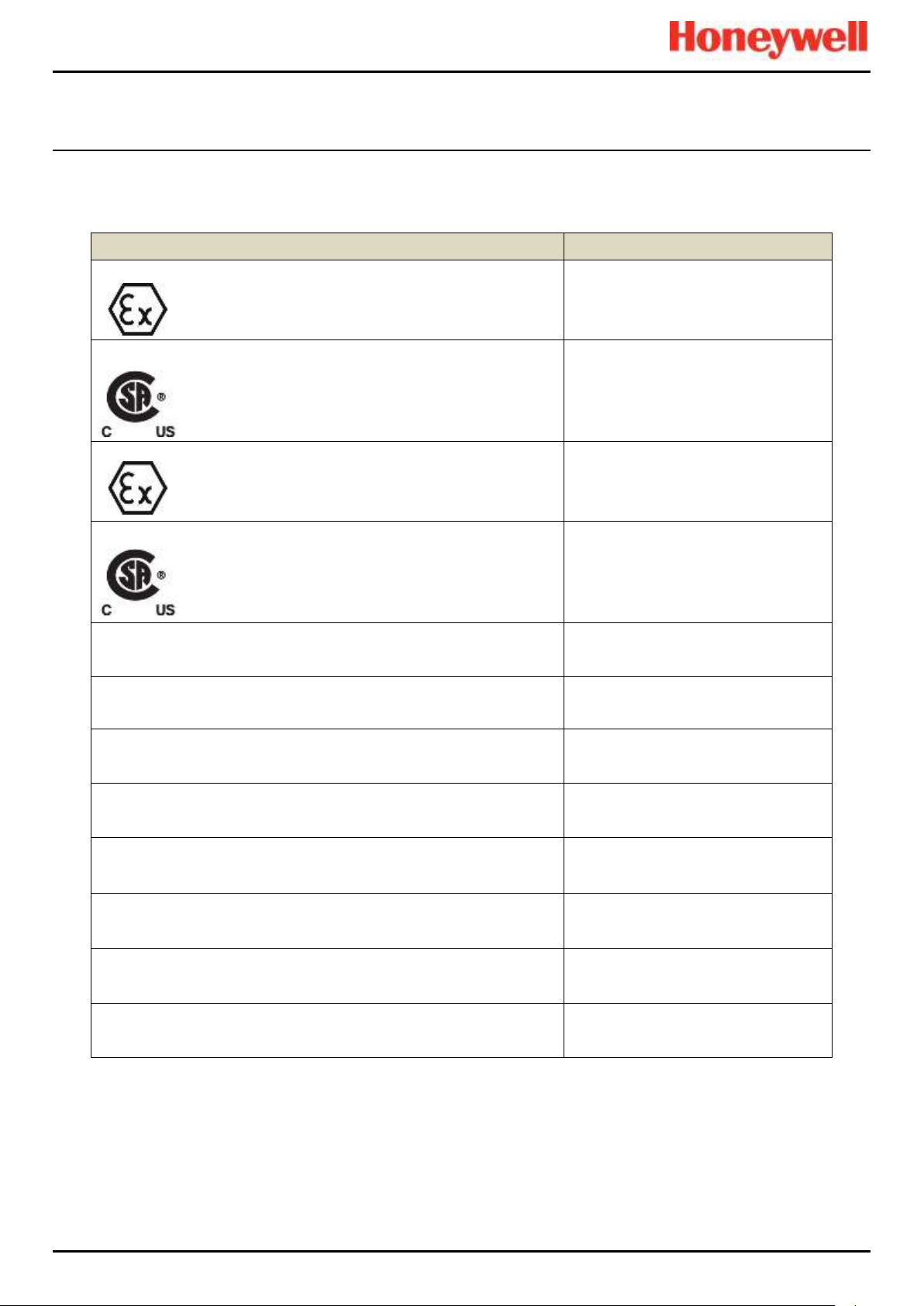
CERTIFICATION
Description
Certificates
Remote Wall Mount Zone 2/Div. 2 Enclosure and ROM (ATEX/IECEx)
II 3G Ex nA nC IIC T4 Gc
(ROM) Tamb –40 °C to +70 °C
(Enclosure) Tamb –40 °C to +xx °C*
* See Rating Plate
Remote Wall Mount Zone 2/Div. 2 Enclosure and ROM (CSA US/CAN)
Class I, Div. 2, ABCD T4
Class I, Zone 2, AEx nA nC IIC T4
Class I, Zone 2, Ex nA nC IIC T4
(ROM) Tamb –40 °C to +70 °C
(Enclosure) Tamb –40 °C to +xx °C*
* See Rating Plate
AIM mA, AIM mV, DIM, RCM and Backplanes (ATEX/IECEx)
II 3G Ex nA IIC T4 Gc
Tamb –40 °C to +70 °C
AIM mA, AIM mV, DIM, RCM and Backplanes (CSA US/CAN)
Class I, Div. 2, ABCD T4
Class I, Zone 2, AEx nA IIC T4
Class I, Zone 2, Ex nA IIC T4
Tamb –40 °C to +70 °C
Remote Wall Mounted Zone 2/Div. 2 Enclosure
SIRA 15ATEX4034X
IECEx SIR15.0021X
CSA 70030437
AIM mA
SIRA 15ATEX4028U
IECEx SIR15.0015U
CSA 70004992
AIM mV
SIRA 15ATEX4029U
IECEx SIR15.0016U
CSA 70025468
DIM
SIRA 15ATEX4030U
IECEx SIR15.0017U
CSA 70025478
ROM
SIRA 15ATEX4031U
IECEx SIR15.0018U
CSA 70025950
RCM
SIRA 15ATEX4032U
IECEx SIR15.0019U
CSA 70025951
Backplanes
SIRA 15ATEX4033U
IECEx SIR15.0020U
CSA 70025953
AOM
to be provided
14.2 National and International Certificates for Zone 2 Div. 2
The TPPR Zone 2 Div. 2 Systems and System Components hold the following National and International Certificates and
Certification Codes:
Table 18. National and International Certificates
Pt. No. 2400M2566_6_EN 80 Operating Manual
Touchpoint Pro
Page 90

CERTIFICATION
14.3 European Performance Approval (DEKRA Exam) for Systems
TPPR has been approved by DEKRA Exam for use in the measurement of oxygen as well as combustible and toxic gases.
The certification marking that is applied to the product is shown below:
Ex II (1) GD
BVS 16 ATEX G 002 X for EN 60079-29-1, EN 50104 and EN 50271
PFG 16 G 002 X for EN 50104, EN 45544-1/2/3 and EN50271
14.3.1 Approved Components
The following system components have been tested and approved by DEKRA Exam
CCB & CCB-R TPPR-V-2120
COB TPPR-P-2110
Local HMI TPPR-V-0852
CM Motherboard TPPR-P-2100
Bus Interface Board TPPR-V-2130
Backplane 10 Way TPPR-P-0540
Backplane 9 Way TPPR-P-0530
Backplane 7 Way TPPR-P-0525
Backplane 5 Way TPPR-P-0520
19” Rack (with HMI) TPPR-V-0602
19” Rack (remote) TPPR-V-0612
Wall Mount Remote (Small) TPPR-V-1215
AIM mA TPPR-V-1000
AIM mV TPPR-V-1010
AOM TPPR-V-1020
DIM TPPR-V-1030
ROM TPPR-V-1040
RCM TPPR-V-1050
Note: The PC configuration software has not been assessed by DEKRA Exam. If this software is used to configure the
TPPR system the configuration must be verified before use, for example by confirming the printed system configuration and
channel configuration reports.
Note: The power supply units have not been assessed by DEKRA Exam. Any suitable power supply may be used.
Pt. No. 2400M2566_6_EN 81 Operating Manual
Touchpoint Pro
Page 91

CERTIFICATION
14.3.2 Special Conditions for Use When Used for Explosion Protection
Refer to certificate BVS16 ATEX G 002 X.
When using 4-20 mA transmitters, pay particular attention to the following:
• - The specifications of the 4-20 mA interface
• - Behaviour with currents less than 4 mA
• - Behaviour with currents in excess of 20 mA
For each channel, the alarm with the highest significance for safety shall be configured as Latching.
Time delayed relays should not be used for safety related purposes. If their use is unavoidable, the delay time shall be set to
the minimum possible for the required operation. The maximum possible rate of increase of gas concentration shall be taken
into account when determining the delay time.
A latching Fault Relay shall be associated with each channel using Sensepoint ppm catalytic sensors to achieve a reliable
indication in the event of the sensor being flooded with high gas concentrations. A Master fault relay may be configured
where appropriate, or one or more designated relays configured in the Cause and effect matrix.
All controls, including digital inputs, inputs from webserver and inputs from Modbus shall be protected against unauthorised
or inadvertent interference or operation.
When monitoring flammable gases or vapours, the following configuration limits shall be observed:
• - The parameter Under Range Fault Limit shall not be set below -10 %FSD.
• - The parameter Zero Suppression Positive shall not be set above +5 %FSD.
The parameter Over Range Warning Latch shall be set to latching when used with remote sensors or transmitters which
may give indications within their measuring range at gas concentrations above the configured measuring range.
When monitoring oxygen, the following configuration limits shall be observed:
• The parameter Under Range Fault Limit or the parameter Zero Suppression Negative shall not be set below
-2 %FSD.
• The parameter Zero Suppression Positive shall not be set above +2 %FSD.
14.3.3 Special Conditions for Use When Used for Measurement of Toxic Gases or Oxygen
Refer to Certificate PFG 16 G 002 X.
When used as EN 45544-2 apparatus, Touchpoint Pro is suitable for use with transmitters where the output at the limit value
is between 4.96 mA and 12 mA.
When using 4-20 mA transmitters, pay particular attention to the following:
• The specifications of the 4-20 mA interface
• Behaviour with currents less than 4 mA
• Behaviour with currents in excess of 20 mA
For each channel, the alarm with the highest significance for safety shall be configured as Latching.
Time delayed relays should not be used for safety related purposes. If their use is unavoidable, the delay time shall be set to
the minimum possible for the required operation. The maximum possible rate of increase of gas concentration shall be taken
into account when determining the delay time.
All controls, including digital inputs, inputs from webserver and inputs from Modbus shall be protected against unauthorised
or inadvertent interference or operation.
When monitoring oxygen, the following configuration limits shall be observed:
• The parameter Under Range Fault Limit or the parameter Zero Suppression Negative shall not be set below
-2 %FSD.
• The parameter Zero Suppression Positive shall not be set above +2 %FSD.
When monitoring toxic gases, the following configuration limits shall be observed:
• The parameter Under Range Fault Limit shall not be set below -10 %FSD.
• The parameter Zero Suppression Positive shall not be set above the lower limit of measurement when used
according to EN 45544-2.
• The parameter Zero Suppression Positive should not be set above +5 %FSD when used according to EN 45544-3.
Pt. No. 2400M2566_6_EN 82 Operating Manual
Touchpoint Pro
Page 92

CERTIFICATION
WARNING
Ambient temperature: Dependent on components fitted; check individual rating plates.
AVERTISSEMENT
Température ambiante : elle dépend des composants assemblés; vérifier individuellement les plages de
température.
14.3.4 Configuration of Relay Outputs for safety-related switching operations
The System State relays and any other relays configured for safety purposes should be wired to a continuously monitored
system for safe operation. This is to ensure that all system faults are detected promptly and appropriate action taken
Each ROM output must be configured as Normally Energized, Alarm Update Enable not selected, and Latch Function
selected, as shown in the following example:
Figure 42. Fault Latch Output Configuration
14.3.5 Compliance with EN 45544-2 (Toxic Gases)
The lower limit of measurement of Touchpoint Pro is 0.08 % of the transmitter’s full scale deflection. Therefore the zero
suppression positive parameter must not be set higher than 0.08 % of the transmitter’s full scale deflection to avoid
suppression of valid measured values.
To maintain compliance with EN 45544 the calibration interval must not exceed 6 months.
Touchpoint Pro is suitable for use with transmitters where the output at the limit value is between 4.96mA as 12.0 mA. Refer
to EN4544-1 Annex A for further information.
14.3.6 Compliance with EN 50104 (Oxygen)
TPPR is approved for measurement of oxygen deficiency, enrichment and inertisation.
14.4 Important Notes on Certification
TPPR is a fully customizable installation, so all of the possible variations cannot be certified in one guide. Instead every
system will have its personalized parameters inscribed on rating labels attached to each major component (i.e. the
Controller, Remote and Battery Enclosures).
For Certification and Information purposes, a tabular overview of the individual components is given in the TPPR Technical
Handbook, Ch.21 TPPR Specifications.
Note 1: The TPPR system contains a number of commercial-off-the-shelf (COTS) items that have been independently
certified by their manufacturers whose certified parameters have been incorporated into the Specification tables.
Note 2: OEMs are responsible for ensuring that their systems are certified in accordance with these tables and any 3rd–party
requirements.
Note 3: Power Supply Fluctuations shall not exceed DC 18 – 32 V SELV Supply or ±10 % of nominal.
Note 4: All equipment in this manual is rated to a maximum altitude of +2000 m (6562 ft.) AGL.
Note 5: Care must be taken that the equipment is not subjected to vibration that exceeds the levels stated in
EN 60079-29-1, EN 45544 and EN 50104.
Pt. No. 2400M2566_6_EN 83 Operating Manual
Touchpoint Pro
Page 93

ORDERING
System ID
Product
Name
Unit Type
Variant*
Ventilation
Plinth
Logo
BIB
CCB-R
UI
See Example
below.
TPPR
HW = Wall
Mount
S = Small
M = Medium
L = Large
+
F = Front
Access
R= Rear
Access
X = None
X = None
X = None
X = None
X = None
L = Local
(With UI)
N = Natural
HF = Floor
Standing
P = 100mm
H =
Honeywell
M = Modbus
R =
Redundancy
R = Remote
(Without UI)
F = Forced
Example:
TPPR–
HW–
MF–
N X H X X
L
S = Supplier Code i.e. Z for HA Poole UK
II = Bill of Materials Issue Number
PPP = Part Code i.e. 842 for a standard WM
Enclosure
YY =Year of Manufacture
WW = Week of Manufacture
NNN = Sequential Serial Number
FS = Front Access Floor Cabinet with 5 Backplanes
RS = Rear Access Floor Cabinet with 5 Backplanes
TS = Small Stainless Steel Wall Cabinet
Z = Zone 2 Div. 2 Stainless Steel Wall Cabinet
15 Ordering Information
15.1 TPPR System ID Configuration
Your TPPR has a unique System ID that incorporates a Globally Unique Identifier (GUID). A typical example might be TPPR–HW–MF–NXHXXL–ZII8421526123, where the first 14
characters show the system's configuration and the last 13 characters are the GUID (see box-out below).
The System ID and GUID are produced in digital, human and barcode reader formats for ease of tracking and quality control. They can be found on both the TPPR rating plate and in the UI
software.
The following table shows how your TPPR System ID is constructed and this GUID can be used to provide valuable information to Technical Support if you need technical help or warranty
service.
Pt. No. 2400M2566_6_EN 84 Operating Manual
Table 19. TPPR Standard System ID Configuration Chart
Touchpoint Pro
Page 94

ORDERING
Item
Description
Part Number
01
SD Card, 4 Gb, FAT32
TPPR-V-0842
02
Analog Input Module 4-20 mA
TPPR-V-1000
03
Analog Input Module mV-Bridge
TPPR-V-1010
04
DC-UPS 40 A Module
TPPR-V-0501
05
Digital Input Module
TPPR-V-1030
06
Relay Output Module
TPPR-V-1040
07
Analog Output Module
TPPR-V-1020
08
Ring Coupling Module
TPPR-V-1050
09
Power Supply Redundancy Module 40 A
TPPR-V-0500
10
PSU 10 A, 240 W, 24 VDC
TPPR-V-0503
11
PSU 20 A, 480 W, 24 VDC
TPPR-V-0504
12
PSU 5 A, 120 W, 24 VDC
TPPR-V-0502
13
Battery Sealed Lead-Acid 12 Ah 12 V (pair)
TPPR-V-0406
14
Battery Sealed Lead-Acid 27 Ah 12 V (pair)
TPPR-V-0405
15
Modbus® Interface Board
TPPR-V-2130
16
Redundant Control Centre Board
TPPR-V-2120
17
Battery Fuse 20 A (Cartridge)
Local Purchase
18
Backplanes Fuse 20 A (White Bladed)
Local Purchase
19
CMA, Light & Fan Fuse 5 A (Brown Bladed)
Local Purchase
20
UPS Fuse 25 A (Yellow Bladed)
Local Purchase
WARNING
The equipment specified in this manual is only to be installed by the Manufacturer’s trained personnel, or by
competent persons trained in accordance with the Manufacturer’s installation instructions.
15.2 TPPR Components Part Numbers
The following table lists some common TPPR components that are held by your local Honeywell Service Centre.
Table 20. Spare Parts List
Please contact your local Honeywell Service Centre (see back page) if you want to order these parts as spares.
Some items are not listed as they are only available to Honeywell Service Centres, OEMs and Partners.
Unlisted expendable items (i.e. air filters) will be replaced as part of routine Field Service if required.
Pt. No. 2400M2566_6_EN 85 Operating Manual
Touchpoint Pro
Page 95

SAFE DISPOSAL
CAUTION – BATTERY HANDLING AND DISPOSAL
Batteries should be disposed of separately from household waste and in accordance with local laws and regulations.
Unwanted batteries shall be taken to a collection point designated by local authorities.
Always dispose of batteries in accordance with the WEEE Directive; do not dispose of them in domestic waste.
CAUTION – HEALTH AND ENVIRONMENTAL HAZARDS
PCB and Backplane e-waste is hazardous due to the presence of toxic substances such as Cadmium, Chromium,
Lead, and Mercury, and flame retardants such as polybrominated biphenyls and diphenylethers.
Always dispose of e-waste in accordance with the WEEE Directive; do not dispose of it in domestic waste.
16 Disposal of Redundant / Unserviceable Parts
TPPR components must be disposed of in accordance with local and international laws. They shall not be disposed of by
incineration or as domestic waste.
16.1 Restriction of Hazardous Substances (RoHS) Directive
TPPR is compliant with the requirements of the RoHS Directive.
16.2 Waste Electrical and Electronic Equipment (WEEE) Directive
This symbol indicates that the product and/or parts of the product may not be treated as household or municipal waste.
Waste electrical products (end of life) should be recovered/recycled where suitable specialist WEEE disposal facilities exist.
For more information about recycling of this product, contact your local authority, your local agent or distributor, or the
manufacturer whose details are on the back page.
16.3 TPPR System Construction
The TPPR system contains the following materials:
16.3.1 TPPR Safe Area Enclosures:
• Powder coated mild steel
• Zintec
• Polyamide PA 6.6 V0 (UL94)
• e-Waste (Backplane, PCB, Copper cables and terminals)
16.3.2 TPPR Battery Enclosure
The TPPR Backup Battery enclosures may contain 12 VDC Sealed Rechargeable Lead-Acid Batteries (SLAB). These
batteries contain toxic and corrosive substances that may cause injury or damage if the batteries become damaged, or if
they are mishandled, incinerated or disposed of incorrectly.
16.3.3 TPPR 19 Inch Rack
• Powder coated mild steel
• Polyamide PA 6.6 V0 (UL94)
• e-Waste (Backplane, PCB, Copper cables and terminals)
16.3.4 TPPR I/O Modules
• Casing – Polyamide PA 6.6 V0 (UL94), grey
• Contents – printed circuit boards (PCB)
Pt. No. 2400M2566_6_EN 86 Operating Manual
Touchpoint Pro
Page 96

SAFE DISPOSAL
16.3.5 TPPR Power Supply Units
• Casing – Back case: Aluminium; Top case (with mesh): Steel with Nickel plating
• Contents – printed circuit boards (PCB)
16.3.6 TPPR Ring Coupling Module
• Casing – Polyamide PA 6.6 V0 (UL94), green
• Contents – printed circuit boards (PCB)
16.3.7 TPPR Backplanes
• Backplane Assemblies (i.e. PCB)
16.3.8 TPPR Packaging
TPPR outer packaging will be cardboard for wall-mounted units and ISPM15 certified 19 mm solid (not machined) woods for
floor standing units. Facilities for recycling are widely available.
TPPR wall-mounted enclosure inner packaging is made from Stratocell® foam. The foam can be recycled and reused as
Stratocell® where such recycling facilities exist.
TPPR floor standing units may be shipped on ISPM15 certified wooden pallets that may be reused, recycled or returned.
Figure 43. ISPM15 Pallet Mark Example
Pt. No. 2400M2566_6_EN 87 Operating Manual
Touchpoint Pro
Page 97

17 Table of Icons
Meaning
T/screen
Icon
PC Config
Icon
About
N/A
About Active User
N/A
Active Events Screen
(no active events)
N/A
Active Events Screen
(with active events)
N/A
Add User
Back
N/A
CCB Configuration
N/A
CCB Management
CCB Replacement
N/A
Configuration Backup
N/A
Configuration Restore
N/A
Delete Configuration
N/A
Diagnostics
Event History
N/A
Meaning
T/screen
Icon
PC Config
Icon
Tool Box
N/A
Filter
N/A
Firmware Update
N/A
Global Settings
N/A
Go to Inputs
N/A
Go to Outputs
N/A
Help
Home
Licence Cancel
N/A
Licence Install
N/A
Licence Manage
N/A
Menu
(T/s: select options in
Input channel detail
screen)
(PC: configure options in
System Settings)
Modbus Settings
N/A
Panel Configuration
N/A
ILLUSTRATIONS
Pt. No. 2400M2566_6_EN 88 Operating Manual
Touchpoint Pro
Page 98

ILLUSTRATIONS
Meaning
T/screen
Icon
PC Config
Icon
Password Change
N/A
Regional settings
N/A
Remove User
N/A
Reports
N/A
Ring Network
Screen Locked
(User Login)
Screen Unlocked
(User Logout)
SD Card
N/A
Select Language
N/A
Sensor Catalogue
Update
N/A
Service Contact Settings
N/A
System Configuration
System Setup
TCP/IP Settings
N/A
Trend Graph Settings
N/A
Meaning
T/screen
Icon
PC Config
Icon
User Management
Zoom in
(X axis)
N/A
Zoom in
(Y axis)
N/A
Zoom out
(X axis)
N/A
Zoom out
(Y axis)
N/A
Figure 44. Icon Table
Pt. No. 2400M2566_6_EN 89 Operating Manual
Touchpoint Pro
Page 99

List of Illustrations
18 List of Illustrations
Figure 1. Electrical Warning Label 1 8
Figure 2. Electrical Warning Label 2 8
Figure 3. Protective Earth (Ground) Point 8
Figure 4. Equipment Earth (Ground) Point 8
Figure 5. Controller Rear Cover with Example Labels 8
Figure 6. Example of a Typical System Rating Label 9
Figure 7. Typical TPPR Product Label 9
Figure 8. Keep Children Away 10
Figure 9. No Naked Flames 10
Figure 10. Use Caution 10
Figure 11. Electrical Hazard 10
Figure 12. Read The Instruction Manual 10
Figure 13. Wear Eye Protection 10
Figure 14. Hazardous Waste (Pb = Lead) 10
Figure 15. Recycle Only 10
Figure 16. TPPR Building Blocks 12
Figure 17. TPPR Controller with Remote Units and Field Devices 13
Figure 18. TPPR Enclosures 14
Figure 19. TPPR Controller Cover with Connection Map 14
Figure 20. TPPR Controller 16
Figure 21. TPPR Backplane 17
Figure 22. TPPR Controller Typical Schematic 17
Figure 23. Example Ring Circuit 18
Figure 24. TPPR Module Types 19
Figure 25. Typical Power Supply Setup 20
Figure 26. Choice of PSU Size (120 W / 240 W / 480 W) 20
Figure 27. Power Redundancy Module Operation 21
Figure 28. DC-UPS and Battery Configuration 22
Figure 29. Battery Circuit 24
Figure 30. System Status Normal 29
Figure 31. System Status with Example Active Events 29
Figure 32. Touchscreen Navigation – Input and Output 30
Figure 33. Touchscreen Navigation – Active Events 31
Figure 34. Input Details Screen 33
Figure 35. Outputs Screen 33
Figure 36. Outputs Screen with filter options 33
Figure 37. Trend Graph Screen 34
Figure 38. Fault Latch Output Configuration 43
Figure 39. Active Events Screen with Filter Options 45
Figure 40. Active Events Screen Showing the Filter Option Buttons 46
Pt. No. 2400M2566_6_EN 90 Operating Manual
Touchpoint Pro
Page 100

List of Illustrations
Figure 41. Inputs Screen with menu options 48
Figure 42. Fault Latch Output Configuration 84
Figure 43. ISPM15 Pallet Mark Example 88
Figure 44. Icon Table 90
Pt. No. 2400M2566_6_EN 91 Operating Manual
Touchpoint Pro
 Loading...