

Page 1
User Guide
Touchpoint Plus
MAN0984_Iss 3_02/16 Touchpoint Plus
Pt. No. 3011M5001_3 i Technical Handbook
Page 2

Revision History
Revision Comment Date
Issue 01 First Issue 04/02/2016
.
MAN0996_Iss 1_02/16 Touchpoint Plus
Pt. No. 3011M5044_EN ii User Guide
Page 3

Disclaimer
In no event shall Honeywell be liable for any damages or injury of any nature or kind, no matter how caused, that arise
from the use of the equipment referred to in this manual.
Strict compliance with the safety procedures set out and referred to in this manual, and extreme care in the use of the
equipment, are essential to avoid or minimise the chance of personal injury or damage to the equipment.
The information, figures, illustrations, tables, specifications, and schematics contained in this manual are believed to be
correct and accurate as at the date of publication or revision. However, no representation or warranty with respect to such
correctness or accuracy is given or implied and Honeywell will not, under any circumstances, be liable to any person or
corporation for any loss or damages incurred in connection with the use of this manual.
The information, figures, illustrations, tables, specifications, and schematics contained in this manual are subject to
change without notice.
Unauthorised modifications to the gas detection system or its installation are not permitted, as these may give rise to
unacceptable health and safety hazards.
Any software forming part of this equipment should be used only for the purposes for which Honeywell supplied it. The
user shall undertake no changes, modifications, conversions, translations into another computer language, or copies
(except for a necessary backup copy).
In no event shall Honeywell be liable for any equipment malfunction or damages whatsoever, including (without limitation)
incidental, direct, indirect, special, and consequential damages, damages for loss of business profits, business
interruption, loss of business information, or other pecuniary loss, resulting from any violation of the above prohibitions.
Conditions of Use
Warranty
Honeywell Analytics warrants the Touchpoint Plus system against defective parts and workmanship, and will repair or (at
its discretion) replace any components that are or may become defective under proper usage within 12 months from the
date of commissioning by a Honeywell Analytics approved representative* or 18 months from shipment from Honeywell
Analytics, whichever is sooner.
This warranty does not cover consumable, batteries, fuses, normal wear and tear, or damage caused by accident, abuse,
improper installation, unauthorized use, modification or repair, ambient environment, poisons, contaminants or abnormal
operating conditions.
This warranty does not apply to sensors or components that are covered under separate warranties, or to any 3
cables and components.
Any claim under the Honeywell Analytics Product Warranty must be made within the warranty period and as soon as
reasonably practicable after a defect is discovered. Please contact your local Honeywell Analytics Service representative
to register your claim.
This is a summary. For full warranty terms please refer to the Honeywell Analytics’ General Statement of Limited Product
Warranty, which is available on request.
* A Honeywell Analytics approved representative is a qualified person trained or employed by Honeywell Analytics, or a
qualified person trained in accordance with this manual.
Copyright Notice
Microsoft, MS and MS–DOS are registered trademarks of Microsoft Corp.
Other brand and product names mentioned in this manual may be trademarks or registered trademarks of their respective
companies and are the sole property of their respective holders.
Honeywell is the registered trademark of Honeywell Automation and Control Systems (ACS).
Touchpoint is a registered trademark of Honeywell Analytics (HA).
Find out more at www.honeywellanalytics.com
rd
-party
MAN0996_Iss 1_02/16 Touchpoint Plus
Pt. No. 3011M5044_EN iii User Guide
Page 4

Conditions of Use
This page deliberately blank.
MAN0996_Iss 1_02/16 Touchpoint Plus
Pt. No. 3011M5044_EN iv User Guide
Page 5

Contents
Chapter 1. Important Information .......................................................................................... 1
1.1 Regulatory Approval Markings ................................................................................................ 1
1.2 Additional Product Markings ................................................................................................... 1
1.3 TPPL Mandatory Warning ......................................................................................................... 1
1.4 TPPL General Warnings ........................................................................................................... 2
1.5 TPPL General Cautions ............................................................................................................ 3
1.6 How to Use this Manual ............................................................................................................ 3
1.6.1 Intended Readers .............................................................................................................. 3
1.6.2 Conventions Used ............................................................................................................. 3
1.6.3 Associated Manuals .......................................................................................................... 4
Chapter 2. Safety Hazards, Warnings and Ca u tions ........................................................... 5
2.1 Safety ......................................................................................................................................... 5
2.1.1 Warnings and Cautions ..................................................................................................... 5
2.1.2 Safety Hazards .................................................................................................................. 6
2.2 Location and Description of Warning Labels ......................................................................... 8
2.2.1 Safety Warning Labels ...................................................................................................... 8
2.3 Electrical Hazards ..................................................................................................................... 9
2.3.1 General Safety Precautions .............................................................................................. 9
2.3.2 Component Testing and Replacement .............................................................................. 9
2.3.3 Antistatic Precautions ...................................................................................................... 10
2.3.4 Good Practice ................................................................................................................. 10
2.3.5 Lithium Battery Hazard .................................................................................................... 10
2.3.6 Product Compliance ........................................................................................................ 11
2.3.7 Conditions of Use ............................................................................................................ 12
2.3.8 Training of Personnel ...................................................................................................... 12
2.3.9 Conditions Satisfying Local, National and International Safety Regulations ................... 12
2.3.10 Due Authorisation .......................................................................................................... 12
2.3.11 Approved Maintenance and Servicing Procedures ....................................................... 12
Chapter 3. System General Description .............................................................................. 13
3.1 How to Open and Close the Enclosure ................................................................................. 15
3.2 Equipment Specification ........................................................................................................ 16
3.2.1 Power Requirements (Controller Unit only) ..................................................................... 16
3.2.2 Weights ........................................................................................................................... 17
3.2.3 Dimensions ..................................................................................................................... 17
3.2.4 Ambient Operating Temperature ..................................................................................... 17
3.2.5 Overall Ambient Operating Humidity ............................................................................... 17
3.2.6 Storage Conditions (Without batteries) ........................................................................... 17
3.2.7 Storage Conditions (With batteries) ................................................................................ 17
3.2.8 IP Rating ......................................................................................................................... 17
3.2.9 Construction .................................................................................................................... 17
3.2.10 Touchpoint Plus Packaging ........................................................................................... 18
3.2.11 Packaging Components for Return to Manufacturer ..................................................... 18
3.2.12 Disposal (WEEE Directive)............................................................................................ 18
3.3 TPPL Construction .................................................................................................................. 18
3.3.1 TPPL Basic Control Unit ................................................................................................. 18
3.3.2 TPPL Expansion Unit ...................................................................................................... 19
3.3.3 TPPL DIP Switches ......................................................................................................... 19
Chapter 4. Touchpoint Plus User Guide ............................................................................. 21
4.1 User Interface General ............................................................................................................ 21
4.2 Touchscreen ............................................................................................................................ 22
4.3 Switching On and Off .............................................................................................................. 22
4.4 Menu Items and Access Levels ............................................................................................. 23
4.4.1 Navigation – Active Access Level Icons .......................................................................... 25
4.5 SD Card Usage ........................................................................................................................ 25
4.5.1 Checking the Capacity of the SD Card ............................................................................ 25
MAN0996_Iss 1_02/16 Touchpoint Plus
Pt. No. 3011M5044_EN v User Gui de
Page 6

Contents
4.5.2 Inserting or Replacing SD Cards ..................................................................................... 26
4.6
Normal Operation (Safety
4.7 Operating Overview ................................................................................................................ 27
4.7.1 Touchscreen ................................................................................................................... 27
4.7.2
User Interface
4.7.3 Navigating the Channel Detail Screens.
6.6.3 Navigation – Active
4.7.4 Navigation – Menu .......................................................................................................... 31
4.8 Responding to Alar
4.8.1
View Active
4.8.2
Accept or Acknowledge
4.8.3
Reset a Latched
4.9
Event Information ................................................................................................................... 33
4.9.1
Viewing Event
4.9.2 Accepting / Acknowledging Active Events ....................................................................... 33
4.9.3
Resetting Latched Events ............................................................................................... 34
4.10
Inhibiting Channels ............................................................................................................... 34
4.10.1 To Inhibit Input Channels: ............................................................................................. 34
4.10.2 To Clear Inhibits: ........................................................................................................... 34
4.10.3 To Change Inhibit Timeouts .......................................................................................... 34
4.11
Viewing Input Channels and Input
4.12
Viewing Output
4.13
Viewing the Trend
4.14 Viewing and Exporting Event History .................................................................................. 38
4.14.1 To View the Event History ............................................................................................. 38
4.14.2 To Export the Event History .......................................................................................... 38
4.15 Accessing the System Information and Service Contact Details...................................... 38
4.16 System State and System Failure Relays ........................................................................... 38
4.17 Monitoring TPPL via the Optional Web Interface ............................................................... 39
4.17.1 Web Interface Configuration ......................................................................................... 39
4.17.2 Web Interface Navigation .............................................................................................. 41
Alarms
Channels
Functions)
Scr
een
.................................................................................................... 27
Events and Filtering
ms......................................................................................................... 32
....................................................................................................... 32
an Active
Alarm
.................................................................................................. 33
Information
.................................................................................................. 36
Graph
................................................................................................... 37
................................................................................. 27
............................................................................ 29
...................................................................... 30
Alarm
.................................................................... 32
.......................................................................................... 33
Details
.................................................................... 35
Chapter 5. Daily / Shift Checks ............................................................................................ 43
Chapter 6. Routine Maintenance and Scheduled Testing ................................................. 45
6.1 Routine Maintenance .............................................................................................................. 45
6.1.1 Weekly Checks ............................................................................................................... 45
6.2 Routine Testing ....................................................................................................................... 46
6.2.1 Exercising the Audio/Visual Alarms ................................................................................. 46
6.2.2 Exercising the Relays ...................................................................................................... 47
6.2.3 Checking the mA Outputs ............................................................................................... 47
6.2.4 Calibrating mV Input Channels........................................................................................ 48
6.3 Periodic Scheduled Testing ................................................................................................... 49
Chapter 7. Repairs, Replacements and Upgrades ............................................................. 51
7.1 Back up Battery Maintenance ................................................................................................ 51
7.1.1 Recommended Backup Battery Maintenance ................................................................. 51
7.1.2 How to Replace the Backup Battery ................................................................................ 51
Chapter 8. Troubleshooting ................................................................................................. 53
8.1 Calling for Technical Support. ............................................................................................... 53
Chapter 9. Fault Codes ......................................................................................................... 54
Chapter 10. Technical Specifications .................................................................................. 55
10.1 Environmental ....................................................................................................................... 55
10.2 User Interface and Main Module .......................................................................................... 55
10.3 External Power Supplies ...................................................................................................... 55
MAN0996_Iss 1_02/16 Touchpoint Plus
Pt. No. 3011M5044_EN vi User Guide
Page 7

Contents
10.4 Backup Battery ...................................................................................................................... 56
10.5 Wall Mount Enclosure ........................................................................................................... 56
Chapter 11. Certifications ..................................................................................................... 57
11.1 EC Declaration of Conformity .............................................................................................. 57
11.2 National and International Certificates of Compliance ...................................................... 58
Chapter 12. Icon Glossary .................................................................................................... 59
Chapter 13. List of Figures ................................................................................................... 61
Chapter 14. List of Tables ..................................................................................................... 61
MAN0996_Iss 1_02/16 Touchpoint Plus
Pt. No. 3011M5044_EN vii User Guide
Page 8

Contents
This page deliberately blank.
MAN0996_Iss 1_02/16 Touchpoint Plus
Pt. No. 3011M5044_EN viii User Guide
Page 9
Introduction
ONLY. READ AND UNDERSTAND THE INSTRUCTION MANUAL COMPLETELY BEFORE
Chapter 1. Important Information
The Equipment referred to in this manual contains components and assemblies that are each certified for use in a variety
of differing environments, and it is the site owner’s responsibility to confirm the suitability of the equipment prior to its
installation and use.
The Equipment assemblies referred to in this manual are collectively certified for use in a flammable gas detection system
only. Any other use is not currently certified and is not authorised by the manufacturer.
Please check the product rating plate and look for the following marks to ensure that the supplied equipment is suitable for
its intended location and purpose:
1.1 Regulatory Approval Markings
Products bearing the CE mark conform to all applicable European Directives as stated on the Honeywell product specific
EC Declaration of Conformity.
Products bearing the UL mark conform to the requirements for Ordinary Locations. The letters C and US mean that the
product is additionally certified for use in Canada and the United States of America.
1.2 Additional Product Markings
Products bearing this mark must not be disposed of in domestic waste. They must always be taken to a specialist Waste
Electrical and Electronic Equipment (WEEE) disposal or recycling facility. A box under the mark may show the type of
hazardous material in the product, e.g. the letters Pb would show that the item contains Lead.
Products bearing this mark are recyclable and should not be disposed of as nor mal landf il l w aste.
1.3 TPPL Mandatory Warning
FOR SAFETY REASONS THIS EQUIPMENT MUST BE OPERATED BY QUALIFIED PERSONNEL
OPERATING OR SERVICING THE EQUIPMENT.
POUR DES RAISONS DE SÉCURITÉ, CET ÉQUIPEMENT DOIT ÊTRE UTILISÉ, ENTRETENU ET
RÉPARÉ UNIQU EMENT PAR UN PERSONN EL QU ALIFI É. ÉTU DIER LE M ANUEL D’IN STRUC TION S
EN ENTIER AVANT D’UTILISER, D’ENTRETENIR OU DE RÉPARER L’ÉQUIPEMENT.
WARNING
ATTENTION
MAN0996_Iss 1_02/16 Touchpoint Plus
Pt. No. 3011M5044_EN 1 User Guide
Page 10

Introduction
1.4 TPPL General Warnin g s
1) The equipment specified in this manual is only to be installed by the Manufacturer’s trained personnel, or by
competent persons trained in accordance with the Manufacturer’s installation instructions.
2) Installation must be in accordance with the recognized standards of the appropriate authority in the country
concerned. Refer to local, national and co mpa ny regulatio ns.
3) Do not operate the Touchpoint Plus system or its components outside of their rated operating specification.
4) Touchpoint Plus must not be operated in Oxygen enriched atmospheres, i.e. greater than 25% v/v Oxygen.
5) All equi pment containing a User Interface must be suitably protected from direct sunlight and rain.
6) Power Supply Fluctuations are not to exceed DC 18 – 32 V SELV Supply or ±10 % of nominal.
7) All versions of Enclosure apparatus are electrical Class 1, and must be connected to Protective Earth (Ground).
8) The Touchpoint Plus instal lation mus t include a m eans of isol ating or di sconnecting t he inpu t voltage supp ly. The
isolation or disconnection device must be conveniently located close to the system and be clearly labelled. For
an AC mains voltage supply, the isolation or disconnection device must disconnect both the line and neutral
poles, but maintain earth (ground) continuity.
9) The Touchpoint Plus input voltage supply must include over-current protection.
10) All cabling must be ap propriately rat ed and approve d in accordanc e with local, nat ional and company regulati ons,
and suitable for the installation. Additionally, cabling must satisfy requirements defined in the manuals of
connected field devices, in particular if the field device is certified for use in a hazardous location.
11) All signal cables and interconnections must be shielded and the shields terminated only at the unified earth
(ground) bus bar situated inside the enclosure
12) All conduits and cable armour shall be bonded to protective earth (ground), and care must be taken to avoid
ground loops and to avoid contact with cable shielding.
13) Cable entry glands, blanking plugs, reducers, adaptors and breather devices must be suitably approved and
must not reduce the IP rating or protection levels. Items should not be used if there is a high risk of mechanical
damage to the equipment or enclosure.
14) Access doors and entry points must be kept closed when the system is energised in normal operation.
15) The TPPL Enclosures must be securely closed and the locking handle security screws must be fully tightened
during normal operation.
16) All equipment in this manual is rated to +2000 m (6562 ft) altitude maximum.
17) For safety reasons this equipment must be operated by qualified personnel only. Read and understand the
Instruction Manual completely bef ore oper at in g or servic ing the equip ment.
18) Touchpoint Plus systems m ay cont ain h az ar dou s live terminals. Appropriate pr ec autions should be taken duri n g
operation, installation, and maint enance and servi cing. Specif ically, operator s must have a ppropriate tra ining and
experience to be aware of the hazards to which they may be exposed, and of measures to min imise risk to
themselves or other people.
19) The protection provided by TPPL may be impaired or lost if the equipment is installed or used in an incorrect,
unspecified or unauthorised way.
20) Be aware that extended exposure of a detector element to certain concentrations of combustible gases and air
can introduce stress to the element that may seriously affect its performance, and therefore recalibration should
be carried out or the sensor replaced, or both, after an alarm due to an indication of a high conce ntr at ion.
21) When used in a Gas Detection summi ng u p r ol e, th e gas reading may be higher t han t he a ctua l c onc entr at ion at
any one detector head location, or it may be the actual concentration at one specific detector head.
22) Exposure to some chemicals may degrade the sealing properties of materials used in the alarm relay.
23) Do not open TPPL enclosures or disconnect/reconnect equipment until power has been isolated and the area is
made safe / non-hazardous. This includes replacing backup batteries.
24) Substitution of any components may impair suitability for Class I, Division 2.
MAN0996_Iss 1_02/16 Touchpoint Plus
Pt. No. 3011M5044_EN 2 User Guide
Page 11
1.5 TPPL General Cautions
1) Touchpoint Plus SMPS, Input and Output Modules have no user serviceable parts. In the unlikely event of a
failure, the item must be replaced using only manufacturer supplied parts.
2) Do not use sharp objects to operate the Touchscreen as this could irreparably damage the User Interface and
adversely affect its IP rating.
3) Use only soft, damp cloths or screen wipes to clean the Touchpoint Plus. Do not use solvents or abrasives as
they will cause irreparab le damage.
4) Once commissioned, Touchpoint Plus is intended for continuous operation.
5) Undo the security screws before pulling the locking handle. Failing to do so may irreparably damage the
enclosure.
6) Do not place any objects on top of the enclosures as this may cause overheating and may cause the enclosure
to fall from the wall.
1.6 How to Use this Manual
Introduction
1.6.1 Intended Readers
This Manual should be read by everyone who operates or monitors the Touchpoint Plus gas detection system.
Only personnel who have been fully trained by Honeywell are authorised to Install, Set-up, Service, and Test, Repair, or
Recondition Honeywell gas detection systems.
Personnel, who work on, or in the area of, the Touchpoint Plus Gas detection system must be made aware of the
Before unpacking the system, please read the documentation that accompanies it.
contents of Chapter 2 – Safety Hazards, Warnings and Cautions.
IMPORTANT
1.6.2 Conventions Used
The following conventions are used in this manual:
Boot up refers to the action of starting the software from cold.
Menu>Configuration>Channel highlights a sequence of commands (including button touches).
mV Sensor refers to a mV Bridge Sensor.
Reboot refers to shutting down and restarting the software without interrupting the power supply.
Restart refers to cycling the power off and then on again.
SELV refers to Safety Extra-Low-Voltage devices.
[Start] highlights unique button touches.
Start up refers to the action of switching on the system.
Touch refers to all direct interactions with the Touchscreen, whether by finger or stylus.
TPPL refers to the Touchpoint Plus Gas Detection System.
MAN0996_Iss 1_02/16 Touchpoint Plus
Pt. No. 3011M5044_EN 3 User Guide
Page 12

1.6.3 Associated Manuals
This TPPL User Guide should be used in conjunction with ancillary component and field device user guides or
documentation.
This TPPL User Guide (MAN 0996) is available in the following languages:
• Chinese (Simplified) Pt. Nr. 3011M5042
• Dutch Pt. Nr. 3011M5043
• English (UK) Pt. Nr. 3011M5044
• French (Canada) Pt. Nr. 3011M5045
• French (France) Pt. Nr. 3011M5046
• German Pt. Nr. 3011M5047
• Italian Pt. Nr. 3011M5048
• Japanese Pt. Nr. 3011M5049
• Korean Pt. Nr. 3011M5050
• Portuguese (Brazil) Pt. Nr. 3011M5051
• Portuguese (Portugal) Pt. Nr. 3011M5052
• Russian Pt. Nr. 3011M5053
• Spanish (Mexico) Pt. Nr. 3011M5054
• Spanish (Spain) Pt. Nr. 3011M5055
• Swedish Pt. Nr. 3011M5056
• USA (English) Pt. Nr. 3011M5057
The supplementary TPPL Modbus Installation and Setup Guide (Pt. No.3011M5027) is available in English, and is
recommended for OEMs and Modbus specialists only.
The TPPL Technical Handbook (Pt. No. 3011M5001) contains detailed information on Installation, Commissioning,
Maintenance, Repairs, Replacements and Upgrades. It is aimed at Honeywell personnel, qualified technical personnel
who are trained on TPPL, Honeywell partners and OEMs, and it is available in English only.
Introduction
MAN0996_Iss 1_02/16 Touchpoint Plus
Pt. No. 3011M5044_EN 4 User Guide
Page 13
Safety
Touchpoint Plus is suitable for use in Class I, Division 2, Groups A, B, C, and D, or non-hazardous locations only.
Chapter 2. Safety Hazards, Warnings and Cautions
2.1 Safety
Incorrect set-up, maintenance, operation or modification of the Touchpoint Plus gas detection system or its installation
may constitute a serious hazard to the health and safety of personnel and their environment. It is therefore imperative that
the contents of this chapter are thoroughly understood by everyone who has access to the gas detection system or its
associated equipment.
When properly installed, this gas detection system enclosure is rated as IP65.
It may be installed in a Pollution Degree 2 (i.e. laboratory, office or control room) or Pollution Degree 3 (i.e. unheated
boiler room) environment as defined by IEC/UL/EN 61010–1: Safety requirements for electrical equipment for
measurement, control and laboratory use.
In all cases, several hazards may be present when operating or servicing the equipment and extreme caution must be
exercised at all times. The hazards that may be encountered include:
• Class 1 electrical hazards (AC 110/220 V, DC 18–32 V)
• Mechanical hazards (Heavy components, swinging access doors, locking handles etc.)
• Environmental hazards (toxic atmospheres)
• Fire and Ignition hazards
Touchpoint Plus is not ATEX/IECEx certified, and it shall only be installed in safe areas where there are no
flammable atmospheres, and where oxygen concentrations cannot exceed 25% v/v O
DANGER
.
2
2.1.1 Warnings and Cautions
Safety of this equipment is reinforced by the use of safety labels that are fixed to the equipment in a visible manner. The
labels used and their location is detailed in Ch.2.2.1 Safety Warning Labels.
Other likely hazard occurrence and severity is indicated throughout this manual by the use of signal words accompanied
by a hazard description and an internationally recognisable hazard symbol, as shown in the three example boxes below:
Danger indicates an imminent hazard that, if not avoided, is extremely likely to result in death or serious
Warning indicates a potentially hazardous situation that, if not avoided, could result in death or serious injury.
Caution indicates a potentially hazardous situation that, if not avoided, may result in minor or moderate injury.
It is also used to alert the user against unsafe working practices and potential damage to equipment.
DANGER
injury.
WARNING
CAUTION
MAN0996_Iss 1_02/16 Touchpoint Plus
Pt. No. 3011M5044_EN 5 User Guide
Page 14
2.1.2 Safety Hazards
live terminals.
The following specific hazards are associated with the installation and use of this equipment:
Touchpoint Plus is Not ATEX/IECEx certified, and it shall only be installed in safe areas where there are no
Touchpoint Plus is suitable for use in Class I, Division 2, Groups A, B, C, and D or non-hazardous locations only.
Lithium batteries may cause severe injury or death if swallowed, and may catch fire or explode if mishandled,
Always handle batteries with care, keep them out of the reach of children, and dispose of them carefully in
Batteries (regardless of type) shall only be handled, fitted, removed or replaced in non-hazardous (safe) areas.
All power supplies must be hard wired and must include a circuit breaker (RCD / RCCB) and, close by and
unobstructed, a means of manually isolating and locking–out the power supply without breaking the protective
Lethal current may be present in this equipment when electrical power is applied and after it is removed. There is
Isolate power before opening electrical access panels. Ensure residual current is fully discharged before touching
Lethal current may be generated both internally and externally to the system. All installations, including
enclosures and external units, must be grounded to protective earth, and must be capable of staying earthed
The Protective Earth (Ground) symbol is shown to the left, and it always has a green background. Do not confuse
The Touchpoint Plus system and/or its sensors may become contaminated by the ambient environment in which
it or they are used. It is the Customer’s sole responsibility to ensure that all appropriate safety precautions are
Safety
DANGER – IGNITION HAZARD
flammable atmospheres, and where oxygen concentrations cannot exceed 25% v/v O
WARNING – LITHIUM BATTERY HAZARDS
recharged, burned or disposed of incorrectly.
accordance with local regulations.
WARNING – LETHAL VOLTAGE PRESENT
earth (ground) connection.
Removable plug/socket connection is not permitted under any circumstance.
WARNING – LETHAL VOLTAGE PRESENT
a risk of death or injury from electrical shock when access doors are open.
WARNING – LETHAL VOLTAGE PRESENT
(grounded) when the power supply is interrupted.
it with the chassis earth and equipment earth symbols shown below it.
WARNING – TOXIC WASTE AND HARMFUL BY-PRODUCTS
taken before handling any components or transferring them to any other party.
.
2
MAN0996_Iss 1_02/16 Touchpoint Plus
Pt. No. 3011M5044_EN 6 User Guide
Page 15
2.1.2 Safety Hazards (Cont.)
The following general hazards are associated with the use of this equipment:
DO NOT USE WATER if a lithium battery overheats or burns, as it may make the fire worse and it may cause an
This equipment contains a number of potentially toxic substances that may pose a health or environmental
hazard if exposed to very high temperatures, VOCs or corrosives, or if improperly handled or disposed of.
Each Touchpoint Plus enclosure is heavy and weighs considerably more when packed. Ensure that a Manual
Handling Risk Assessment is carried out before moving or installing the system, and ensure that enclosures are
Touchpoint Plus uses high energy AC and DC currents that may cause arcing and sparks if shorted out. Always
Touchpoint Plus can be used to control loud alarms and sirens. Always wear hearing protection when working in
Touchpoint Plus houses static-sensitive component s. Alw ay s isol ate power and discharge circuits before
Always follow a Safe System of Work when carrying out any work involving Safety Systems.
Safety
WARNING – FIRE OR EXPLOSION HAZARD
Batteries may explode if mistreated. Do not disassemble them or dispose of in fire.
WARNING – DO NOT USE WATER
explosion.
Evacuate the area immediately and call Emergency Services.
CAUTION – HEALTH AND ENVIRONMENTAL HAZARDS
CAUTION – RISK OF INJURY AND DAMAGE
fitted securely to a suitable vertical surface. Do not place objects on the enclosures.
CAUTION – RISK OF EYE INJURY
wear eye protection when the enclosure is open.
CAUTION – RISK OF HEARING DAMAGE
the vicinity of loud or high-pitched noises.
CAUTION – RISK OF EQUIPMENT DAMAGE
touching internal components. Always take anti-static precautions.
CAUTION – RISK OF INJURY OR DAMAGE
MAN0996_Iss 1_02/16 Touchpoint Plus
Pt. No. 3011M5044_EN 7 User Guide
Page 16
Safety
2.2 Location and Description of Warning Labels
2.2.1 Safety Warning Labels
In accordance with the requirements of European Standard EN 60825–1, appropria t e warning labels are mounted in
specified locations on the equipment. This is to indicate conditions under which the user could be subjected to electrical
hazards.
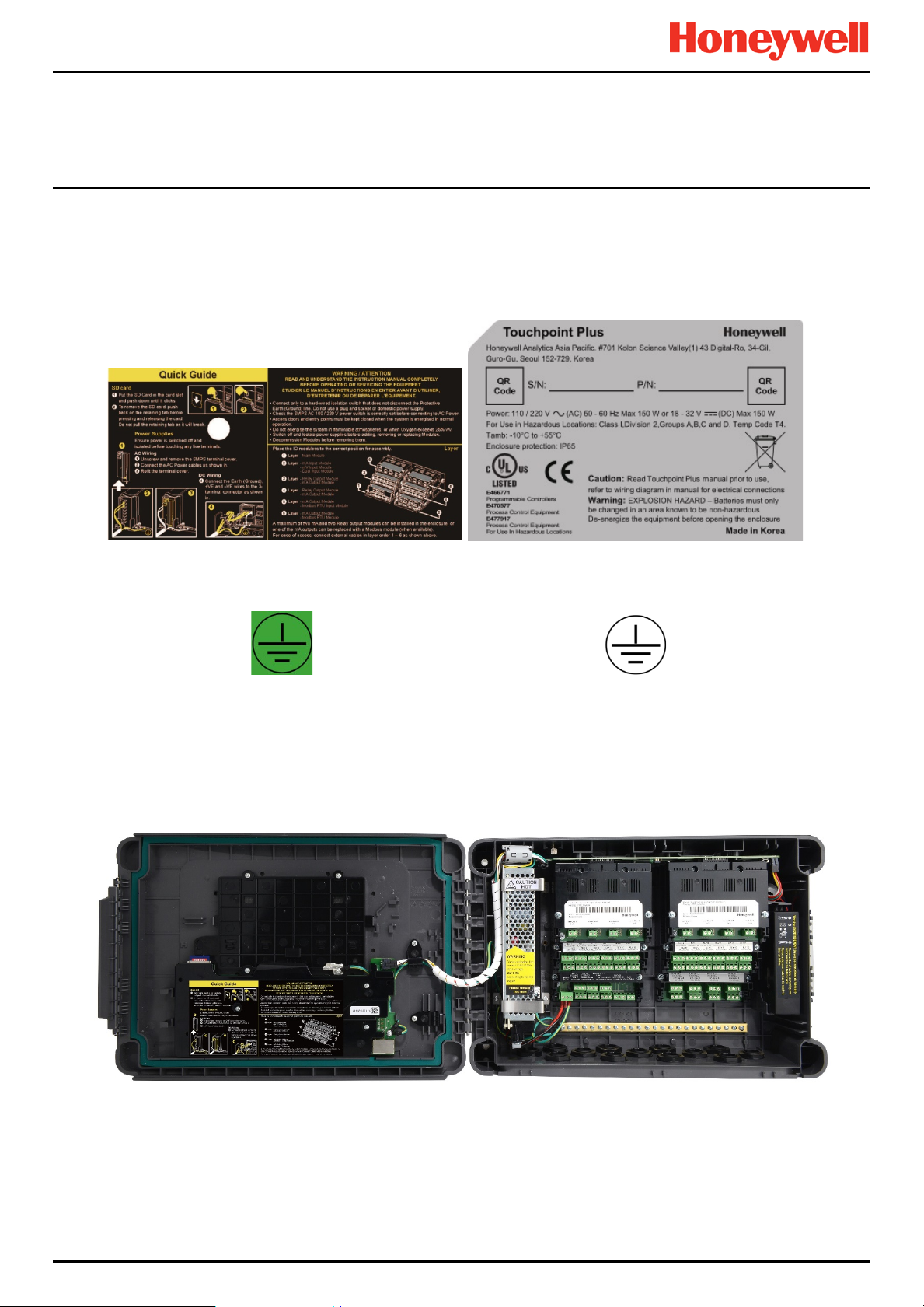
Figure 1. Quick Start Guide Label
(Not to Scale)
Figure 3. Protective Earth (Ground) Point Figure 4. Equipment Earth (Ground) Point
This Protective Earth (Ground) location point label is
used inside the system and is not normally visible to
the operator.
Figure 5. Internal Label Positions
This Equipment Earth (Ground) location point label is
used inside the system and is not normally visible to
the operator.
Figure 2. Rating Label
(External – Not Shown Below)
MAN0996_Iss 1_02/16 Touchpoint Plus
Pt. No. 3011M5044_EN 8 User Guide
Page 17
2.3 Electrical Hazards
Gas detection systems contain electr i cal sup pli es that are potentially dangerous and hence suitable precautions must
be taken to prevent the risk of electrocution. This is especially important when untrained/unqualified persons are
allowed to open the enclosure (e.g. to access/remove/refit the SD Card).
2.3.1 General Safety Precautions
• Read the relevant manual before beginning any operating or service procedures.
• Only personnel trained and certified by Honeywell are authorised to service, fit or remove internal parts.
• Only the minimum number of trained personnel, consistent with safety, should have access to the area while work is
being carried out. If necessary, erect warning signs and barriers.
• Follow accepted working procedures and codes of practice as well as the electrical safety code for the site where the
equipment is installed.
• Never operate the equipment under normal conditions with d oor s open , access panels removed or shorting links
fitted.
• Do not ‘Live Test’ without a Safe System of Work (SSoW).
• Always keep the area around the equipment dry and free of obstructions.
• Switch off and Isolate the equipment if water ingress is suspected or confirmed.
• Never operate the equipment if any Mains power cable is frayed or damaged.
• Never wear wristwatches, rings, bracelets, or other jewellery when working around electrical circuits or moving parts.
• Take anti-static precautions when working on electronic circuits.
• Never work on electrical equipment alone.
Safety
2.3.2 Component Testing and Replacement
Before carrying out any electrical testing or component replacement:
• Read this Manual to become familiar with the location of high voltage components.
• Isolate the system at the main circuit breaker, loc k it in the ‘Off’ position, and attach a notice indicating that
maintenance work is in progress.
• Always wait for 5 minutes after isolating the equipment to ensure that stored energy has dissipated.
• Never assume the polarity of cabling or replacement components. Refer to electrical schematics or contact Honeywell
for confirmation.
• Use only Honeywell approved replacement parts.
Only Honeywell trained and certified maintenance technicians are authorised to carry out component testing and
replacement. Unauthorised work may result in a potentially dangerous situation and will invalidate the
Antistatic Precautions are required to prevent severe damage to electronic components.
WARNING – UNAUTHORISED PERSONNEL
ANTI–STATIC PRECAUTIONS
manufacturer’s warranty.
MAN0996_Iss 1_02/16 Touchpoint Plus
Pt. No. 3011M5044_EN 9 User Guide
Page 18
2.3.3 Antistatic Precautions
Batteries shall only be fitted, removed or replaced in non-hazardous (safe) areas.
As with all modern electronic circuits, the Printed Circuit Boards (PCBs) in Touchpoint Plus systems utilise some staticsensitive components that can be severely damaged if subjected to static discharge. Static can be generated on the
human body by friction or movement and is discharged through the first contacted route to earth. It can also jump gaps
between items of differing electrical potential.
Static damage is not always immediately apparent and can cause component failure at any time after the static discharge
has occurred. It is, therefore, very important that everyone takes the following precautions when handling PCBs:
• An industry approved antistatic wrist strap, containing a resistive component greater than 1Megohm, must be worn
and connected to an effective earth (ground) point. The continuity between the strap and earth (ground) must be
checked regularly.
• PCBs must only be handled by their non-conductive edges. Do not allow any components, conductive tracks or
contacts to come into proximity with the body, clothing, machinery, power source or any material other than a staticdissipative mat.
• W ith the exception of assemblies containing batteries, anti-static packaging must be used for transporting PCBs and
Integrated Circuits (ICs). All Touchpoint Plus electronic components are shipped in appropriate packaging that can be
re-used when returning items for test or repair.
• Avoid wearing clothing manufactured from, or containing a high proportion of, man-made fibres. These can build up a
high static potential that may not be discharged through the body or wrist strap.
An effective earth (ground) point is the protective earth (ground) bus bar inside the enclosure. This can be used to conne ct
a suitable anti-stat ic w r ist st rap provided that the Gas detection system is connected to protective earth (ground) via the
mains power supply cable.
If installed correctly, the equipment earth (ground) point is co nnec ted dire ctly to mains earth (ground) via
protective earth and the mains power supply cable, and the earth (ground) circuit cannot be broken by operating
Safety
IMPORTANT
the Isolator switch or circuit breaker.
2.3.4 Good Practice
After switching off the system, it is good practice to wait at least 15 seconds before switching it on again. This allows the
circuits and RAM to discharge adequately before being powered-up again. Failing to do so may cause data corruption.
2.3.5 Lithium Battery Hazard
Lithium batteries are fitted to Touchpoint Plus as backup power sources.
Replace the factory installed battery pack TPPLOIBB with Honeywell Analytics Asia Pacific replacement battery pack part
no. TPPLSIBB and the PCB CMOS battery with type CR2032 only.
Use of other batteries may present a risk of fire or explosion.
Lithium batteries may cause severe injury or death if swallowed, and may catch fire or explode if mishandled,
Always handle lithium batteries with care, keep them out of the reach of children, and dispose of them carefully
LITHIUM BATTERY TOXIC AND FIRE HAZARDS
recharged, burned or disposed of incorrectly.
in accordance with local regulations.
MAN0996_Iss 1_02/16 Touchpoint Plus
Pt. No. 3011M5044_EN 10 User Guide
Page 19
2.3.6 Product Compliance
This product complies with the following standards and direct iv es.
Other safety directives may apply to the complete system installation if an OEM’s product is integrated into other
equipment or machinery.
Safety
Safety Compliance
Hazardous Location
(Non-Incendive)
Electrical Safety
EMC/RFI
Low Voltage Directive
Gas Performance*
* ISA 12.13.01 and CSA C22.2 No.152 approvals are applicable only to mV sensors Model 705 and MPD or any suitably
certified mA sensor.
Note: The Equipment referred to in this manual contains components and assemblies that are each certified for use in a
variety of differing environments, and it is the site owner’s responsibility to confirm the suitability of the equipment prior to
its installation and use.
Please check the product rating plate and look for the following marks to ensure that the supplied equipment is
suitable for its intended location and purpose:
Products bearing the CE mark conform to all applicable European Directives as stated on the Honeywell product specific
EC Declaration of Conformity.
Products bearing the UL mark conform to the requirements for Ordinary Locations. The letters C and US mean that the
product is certified for use in Canada and the United States of America.
Read and understand the instruction manual before operating or servicing the equipment.
Class 1, Division 2, Groups A,B,C,D, Temp. Code T4
ISA 12.12.01-2013
CSA C22.2 No. 213-M1987
CAN/CSA C22.2 No. 61010-1 and No.142
rd
UL 61010–1 (3
IEC/EN 61010–1 (3rd Edition)
EN 50270
IEC/EN 61010–1 (3
ISA 12.13.01 and CSA C22.2 No. 152
Edition); UL508
rd
Edition)
IMPORTANT
MAN0996_Iss 1_02/16 Touchpoint Plus
Pt. No. 3011M5044_EN 11 User Guide
Page 20

Safety
2.3.7 Conditions of Use
This Touchpoint Plus equipment shall only be operated:
• By properly trained personnel.
• Under Honeywell approved conditions.
• W ith due authorisation.
• Using approved maintenance and servicing procedures.
2.3.8 Training of Personnel
Honeywell and / or its distributors can provide training for operators and maintenance personnel. Personnel who have
been trained in operation and maintenance shall be limited to carrying out only those procedures and tasks taught during
the training course. Honeywell certified maintenance technicians must carry out all other tasks.
Honeywell can also provide additional or advanced training. Retraining is recommended periodically and whenever the
equipment / installation is changed or upgraded.
2.3.9 Conditions Satisfying Local, National and International Safety Regulations
Approved conditions must satisfy the requir em ents of applic able national and international safet y standar ds and stat utor y
requirements relating to electrical, EMC, and health hazards. In addition, they must satisfy the requirements of the Site
Safety Officer and the local safety regulations.
2.3.10 Due Authorisation
Before any production, maintenance, or servicing procedure is carried out; written authorisation must be obtained from
one of the following personnel to confirm that the proposed task satisfies the necessary safety conditions:
• A competent authorised person having a professional qualification in an appropriate technical discipline.
• The Factory, Technical or Engineering Manager responsible for the working area.
• The Site Safety Officer or an authorised Honeywell representative or approved distributor.
2.3.11 Approved Maintenance and Servicing Procedures
Approved Maintenance and Servicing Procedures are those stipulated in this manual or as authorised separately by
Honeywell.
It may be necessary to establish a temporary Locally Controlled Area (LCA) to restrict access during maintenance, testing
or servicing of this equipment.
MAN0996_Iss 1_02/16 Touchpoint Plus
Pt. No. 3011M5044_EN 12 User Guide
Page 21
General Description
SD Card
Audio / Visual Alarm
mA Loop Sensors
Relays / Actuators
mA Loop
mV Bridge Sensors
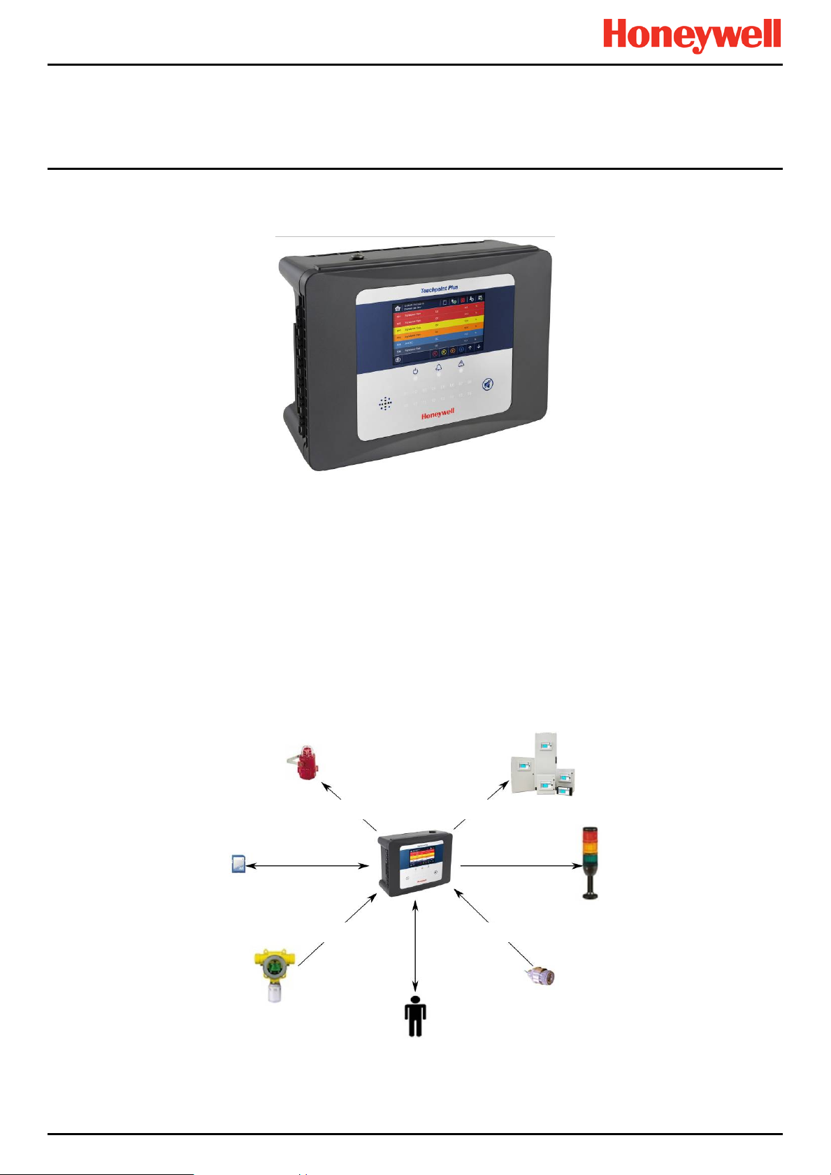
Chapter 3. System General Description
Figure 6. T ouchpoint Plus Wall-Mounted Controller
The Touchpoint Plus is an entry level (or upgrade) touch-screen digital Controller for general industrial and commercial
gas detection systems. It has eight input channels, with a further eight channels available through an optional expansion
unit (see Note below).
It can handle a wide range of milliamp, millivolt, and catalytic sensors through analogue inputs, and it can contr ol vari ous
outputs such as audible and visible signals and solenoid valves.
The cabinets are constructed from high-impact plastic and have full y -s ealed, easy opening access. They are supplied with
a wall mounting or can be directly mounted to any solid vertical surface or rack. Cable entry is via entry glands on the
lower side.
Touchpoint Plus is rated IP65, which means that it is dustproof and can be subjected to low-pressure water without
significant ingress. This makes it particularly suited to offices, control rooms and unheated boiler rooms.
Note: Currently Touchpoint Plus is only available as a composite Gas Detection System, but please contact Honeywell
Analytics for details about future upgrades.
Figure 7. Typical Installation Options
MAN0996_Iss 1_02/16 Touchpoint Plus
Pt. No. 3011M5044_EN 13 User Guide
Page 22
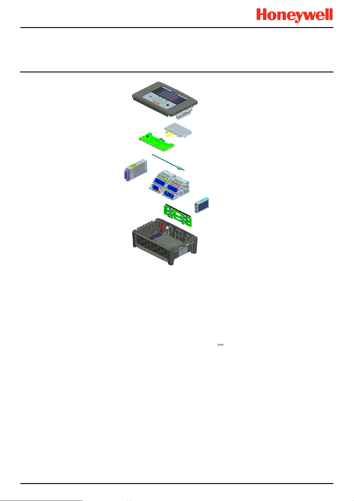
General Description
Enclosure Door
with Touchscreen
Motherboard
SMPS
Modules
Backplane
Enclosure
LCD Unit
Common Data
Communication Cable
Backup Battery
Figure 8. TPPL Controller Exploded View
Both the Touchpoint Plus and its optional expansion unit have the option for AC, DC and battery backup power supplies,
but the optional Expansion Unit has no motherboard or display (LCD).
Features of the Controller unit:
• Colour LCD Touch Screen with multi-language GUI and menus
• Password protection
• Flexible Mains Power Input: 50 – 60 Hz 110/220 V ~ (AC), 18 – 32 V
for combined Base and Expansion Units
• Up to 8 channels of Analogue Input (0–22 mA, Bridge mV for Cat bead)
• 2 or 3-wire signal inputs
• Up to 24 channels of user configurable relay controlled Output
• Up to 8 channels of configurable mA Output
• Alarm update on Acknowledge
• Automatic Self-Diagnostic with error codes
• Event recording
• SD Card
(DC), Max 105 W for a single unit or 210W
Pt. No. 3011M5044_EN 14 User Guide
MAN0996_Iss 1_02/16 Touchpoint Plus
Page 23
General Description
1 2 3
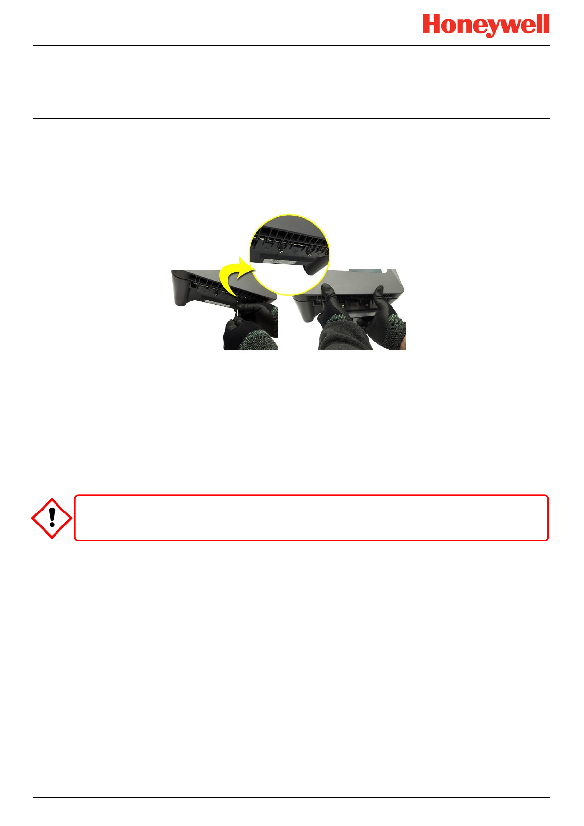
3.1 How to Open and Close the Enclosure
1) Ensure that it is safe to open the enclosure and, if necessary switch off and isolate electrical power.
2) Unscrew the two x 3 mm Hex socket security screws (1) until they become loose (2).
3) With a gloved hand only, pull the handle until it comes free (3). Do not apply undue force.
4) Open the enclosure door fully.
Figure 9. Undoing the Two Security Screws and Opening the Enclosure
5) Closure is the reverse of this procedure, but care must be taken not to exert undue force, and you must not press on
the membrane or touch screen areas.
Note: The door recess has an environmental seal that requires some pressure to close the door correctly. The enclosure
handle is the primary method of applying this pressure but you can assist it by pressing firmly on the door edge directly
above the handle as you press on the handle itself.
TPPL enclosures must be fully closed and secured during normal operation.
CAUTION
MAN0996_Iss 1_02/16 Touchpoint Plus
Pt. No. 3011M5044_EN 15 User Guide
Page 24
General Description
3.2 Equipment Specification
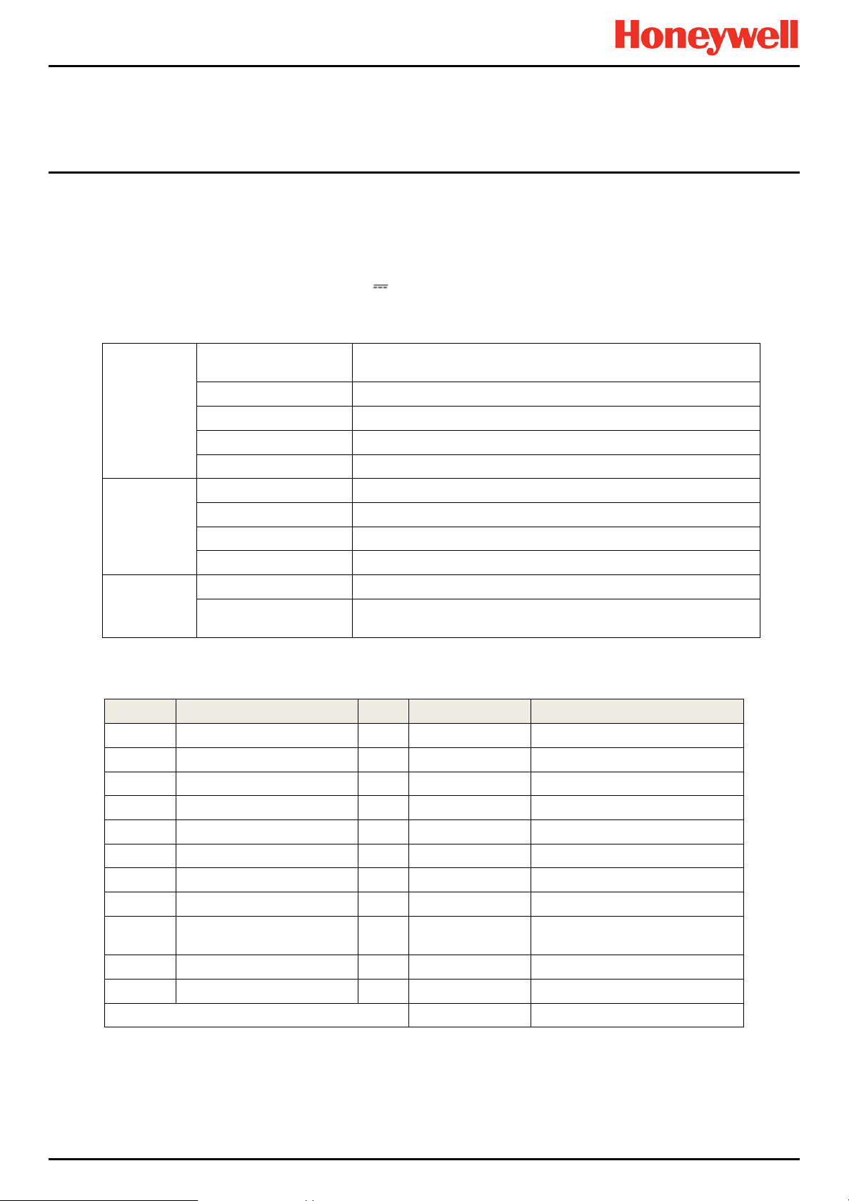
3.2.1 Power Requirements (Controller Unit only)
The Touchpoint Plus system is designed to operate on a single phase, 50 to 60 Hz, 110/220 V~ (AC) supply with a typical
power consumption of less than 105 W.
Alternatively it can be connected to an 18–32 V (DC) supply with typical power consumption less than 105W.
The system can contain an optional backup battery to guard against short-term power disruption.
Voltage Range AC
AC Frequency Range 50 – 60 Hz ± 6%
Input
Output
Protection
Nr. Power Usage Qty Max Power (W) Remarks
1 UI Module 1 3.6
2 Main Module 1 1.7
3 mA Input Module 1 0.9 Not includin g Field Device power
4 mA input Field Devices 8 40.0 mA Input Module power only
5 mV Input Module 1 8.5
6 Dual Input Module 1 9.4
7 mA Output Module 2 8.6
8 Relay Output Module 2 2.0
9
10 Audio/Visual Alarm 4 28.8
11 SMPS Power Loss — 14.0
MAXIMUM PERMITTED CONSUMPTION 104.9
AC Current Draw (typ.) 3 A @ 115 VAC, 2A @ 230 VAC
Cold-start Current (typ.) 40 A @ 230 VAC
Leakage Current <2 mA @ 240 VAC
DC Voltage 24 V
Rated Current 6.5 A
Current Range 0 – 6.5 A
Rated Power 156 W
Overload 110 – 150 % rated output power
Over-Volt
Table 1. Power Supply (SMPS RS–150–24) Electrical Ratings
Charging power for backup
battery pack
AC 110/220 V manually switchable
300 VAC surge for 5 sec without damage
27.6 – 32.4 VDC Hiccup mode, which recovers automatically when
the fault is removed.
1 5.3
Table 2. Maximum Power Consumption Calculations
MAN0996_Iss 1_02/16 Touchpoint Plus
Pt. No. 3011M5044_EN 16 User Guide
Page 25

3.2.2 Weights
Note: Based on one input module, two mA output modules, two output relays, SMPS and backup battery for the basic unit
and expansion unit respectively.
3.2.3 Dimensions
General Description
TPPL Basic Unit TPPL Expansion Unit
System alone
System with packaging
Table 3. System Weights
External Dimension Millimetres Inches
Depth
Length
Width
Table 4. System Dimensions
8.5 Kg (18.7 lbs) 8 Kg (17.6 lbs)
9 Kg (20 lbs) 8.5 Kg (18.7 lbs)
156 6.2
426 16.9
300 11.8
3.2.4 Ambient Operating Temperature
–10 °C to +55 °C (14 °F to 131 °F)
3.2.5 Overall Ambient Operating Humidity
5 % to 95 %RH, non-condensing
3.2.6 Storage Conditions (Without batteries)
–25 °C to +60 °C (-13 °F to 140 °F), @ 5 % to 95 %RH, non-condensing
3.2.7 Storage Conditions (With batteries)
1 year: –20 °C to +25 °C (–4 °F to +077 °F)
3 months: –20 °C to +45 °C (–4 °F to +113 °F)
1 month: –20 °C to +60 °C (–4 °F to +140 °F)
3.2.8 IP Rating
The enclosures are sealed to IP65 when appropriate cable entry glands are used.
3.2.9 Construction
The system cabinets are constructed from PC ABS plastic with a secured quick release front access door panel.
The Controller door panel holds a touch sensitive colour LCD with a membrane cover over additional buttons, LEDs and
an audible warning horn.
Inside the Controller cabinet is a Switched-Mode Power Supply (SMPS) providing a nominal DC 24 V output, an optional
Lithium-ion backup battery, a Main Module, a mA/mV Input Module, two mA Output Modules, two Relay Modules,
protection fuses, and the control and user interface electronics.
The optional expansion unit holds the same modules and optional backup battery, but has no controller or user interface.
Both enclosures contain a common Earth (ground) rail that must be bonded to Protective Earth (Ground) through an
isolation switch that does not disconnect the Earth line.
MAN0996_Iss 1_02/16 Touchpoint Plus
Pt. No. 3011M5044_EN 17 User Guide
Page 26

General Description
1 2 4 5 6
7
14
15
3
8 9 10
16
11
13
12
3.2.10 Touchpoint Plus Packaging
• Touchpoint Plus outer packaging is made from cardboard. Facilities for recycling are widely available.
• Touchpoint Plus inner packaging is made from Stratocell
recycled into new Stratocell
®
where such recycling facilities exist.
3.2.11 Packaging Components for Return to Manufacturer
Honeywell is unable to accept any consignment that does not conform to the European Classification, Labelling and
Packaging (CLP) Regulations (EC) 1272/2008.
Please consult your distributor, supplier, or the manufacturer if you require further advice.
3.2.12 Disposal (WEEE Directive)
The system contains Lithium batteries and a number of homogenous hazardous materials. These should be disposed of
carefully in accordance with the WEEE Directive and local laws and guidelines. Under no circumstances can they be
disposed of as domestic waste.
3.3 TPPL Construction
The TPPL system consists of a basic Control Unit and an optional Expansion Unit, as shown below.
3.3.1 TPPL Basic Control Unit
This figure shows the building blocks of the basic Touchpoint Plus system.
Figure 10. Controller Unit Layout Before Installation
®
, Low-Density Polyethylene (LDPE) foam. The foam can be
1
Touchscreen PCB
2
SD Card
3
Motherboard
4
Modbus Terminals (option)
5
Ethernet Connector
6
Switched Mode Power Supply
7
DIP Switch (on backplane)*
8
Battery On / Off Switch
* The DIP Switch (14) is used to enable / disable the optional expansion box. See Ch.3.3.3 TPPL DIP Switches for further
information.
MAN0996_Iss 1_02/16 Touchpoint Plus
Pt. No. 3011M5044_EN 18 User Guide
9
Battery Connector
10
mA Output Modules
11
Relay Output Modules
12
Main Module
13
Input Module (mA/mV/Dual)
14
Backup Battery
15
Power Terminal
16
Earth (Ground) Bus Bar
Page 27

3.3.2 TPPL Expansion Unit
1
2 4 5 6 7
14
11
15 3 10 8 9
16
13
12
This figure shows the building blocks of the Touchpoint Plus Expansion Unit.
General Description
Figure 11. Expansion Unit Layout Before Installation
1
No Touchscreen
2
No SD Card
3
No Motherboard
4
No Modbus Terminals
5
No Ethernet Connector
6
Switched Mode Power Supply
7
DIP Switch (on backplane)*
8
Battery On / Off Switch
3.3.3 TPPL DIP Switches
TPPL Backplanes have a DIP switch (item 14 in the figures above) that controls the interaction between the master (basic)
and the optional expansion unit backplanes. Once set these DIP switches need not be altered.
Basic Unit
Both On
9
Battery Connector
10
mA Output Modules
11
Relay Output Modules
12
Main Module (Power and CAN only)
13
Input Module (Dual shown)
14
Backup Battery
15
Power Terminal
16
Earth (Ground) Bus Bar
Basic Unit with Slave
1 On, 2 Off
Expansion Unit
1 Off, 2 On
Figure 12. Backplane DIP Switch Settings
MAN0996_Iss 1_02/16 Touchpoint Plus
Pt. No. 3011M5044_EN 19 User Guide
Page 28

General Description
This page deliberately blank.
MAN0996_Iss 1_02/16 Touchpoint Plus
Pt. No. 3011M5044_EN 20 User Guide
Page 29

Daily Operation
Take alternative site safety precautions while power is off.
Local Accept /
Reset Button
Chapter 4. Touchpoint Plus User Guide
Opening the enclosure may expose live electrical circuits. Touching exposed terminals or wires may cause death
or serious injury. Always turn off and isolate the system before opening the door. Do not switch back on until the
The TPPL Touchscreen is the primary control and viewing method but there is also an optional Web Interface that
currently allows remote viewing only (see Ch.4.17 Monitoring TPPL via the Optional Web Interface for more details).
door is reclosed and secured. Do not operate TPPL with the door insecure.
4.1 User Interface General
Figure 13. Touchpoint Plus Controller User Interface
WARNING
The User Interface panel (shown above) has:
• A colour Touch screen for normal system operation, maintenance and configuration
• Power, Alarm / Fault and Inhibit state LEDs
• Active Channel (01 to 08) status indicators (Ch. 07 is not commissioned in this example)
• Active Expansion Channel (09 to 16) status indicators (not commis sio ned abov e)
• Accept* / Reset membrane button (arrowed above)
• Integral Alarm Buzzer (Left side)
*The membrane button acknowledges and silences active alarms and resets latched alarms, depending on the situation
and how long it is pressed. See Ch.4.8 Responding to Alarms for further information.
Further System Interfaces consist of:
• Remote inhibit and remote reset terminals in the Main module
• One fixed relay and two configurable relays in the Main Module for system Failure, Alarm and Inhibit
• Three dedicated alarm outputs for visual and audio alarms
• An SD Card slot for data logging and firmware/software updates
• An optional expansion unit with optional dual input module (mV & mA)
• Optional remote Web Interface networking via RS485 port
• Optional remote Modbus TCP/IP via hard-wired terminal
MAN0996_Iss 1_02/16 Touchpoint Plus
Pt. No. 3011M5044_EN 21 User Guide
Page 30

4.2 Touchscreen
The Touchscreen is touch only; it has no swipe or pinch gestures.
The Touchscreen has four access levels: View mode is available to all users while Configuration, M aintenan ce and
System Test functions are password protected. (See Ch.4.4 Menu Items and Access Levels for further information.)
There are only three passworded accounts: Administrator, Service and Operator, and their passwords must be carefully
guarded.
Lost passwords can only be replaced by someone higher which, in the case of the Administrator, will be a Honeywell
representative.
Password holders should be assigned to one access level only.
4.3 Switching On and Off
Before switching power on, ensure that the system has been commissioned or that a qualified person has checked that
the wiring is safe and conforms to local regulations. Also check that the battery isolator switches are ‘On’ and that an SD
Card is fitted. Check that the optional expansion unit battery switches are on too.
Switch on power at the Isolator switch and wait for the system to initialise . (The system start up sequence may last for up
to 5 minutes depending on the number of channels in use.)
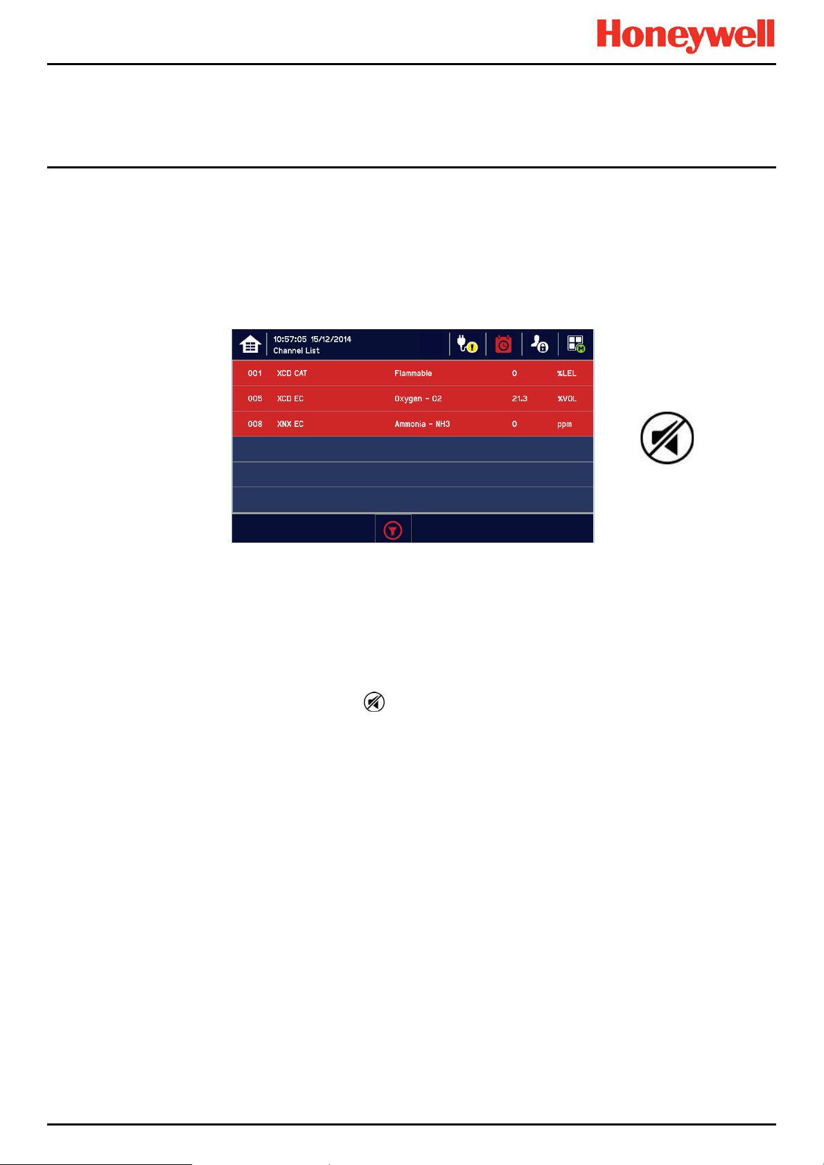
TPPL will first display the auto-scrolling Input screen, indicating the current status of the system. The Channel List View is
shown below. The screenshot shows installed sensors but it may be blank depending on your system status:
You can alter the screen views or gain further information by touching the icons shown below:
Toggle to select screen layout
SD Card Status Good
SD Card Status Fault
External mains power is connected.
Touch for status
External power is not connected.
Touch for status
Event History (changes colour to show
fault, inhibit or alarm)
Further Menu Options
Daily Operation
Table 5. Home Screen Menu Icons
Admin Logged in
Service Logged in
Operator Logged in
No one Logged in
Toggle auto-scroll on and off
Scroll up when auto-scr oll dis a bled
Scroll down when auto-scroll disable d
MAN0996_Iss 1_02/16 Touchpoint Plus
Pt. No. 3011M5044_EN 22 User Guide
Page 31

Daily Operation
4.4 Menu Items and Access Levels
The table below details the menu items and access levels for the User Interface. The password hierarchy is Administrator,
then Service, then Operator. Broadly speaking, the Administrator can do everything, the Service Engineer can edit
channel configuration and do maintenance and calibration, and the Operator can view, acknowledge and reset events.
(Viewing basic System Information and Status does not require a password.)
A user can log in by touching the log in icon, selecting an access level and then inputting a valid password.
Note: Default Authentication timeout follows 15 minutes of inactivity. For security reasons do not leave the Touchscreen
unattended while logged in.
There are two kinds of timeout in menu mode. One is ‘menu timeout’ and the other is ‘authentication time out’.
With ‘menu timeout’, the display will change to a higher menu and then back to the Channel Status screen if there is no
touch input for a pre-set time. The default menu timeout is 90 seconds, but this can be changed using menu options
Configuration>General>Timeout.
For security reasons ‘authentication timeout’ will log you out automatically when there is no Touchscreen activity during
the set time. Changes may be lost and the user will have to log in again.
Items with a clock symbol timeout after 15 minutes of inactivity.
Key: = Allowed, = Denied, = Fixed timeout.
= sub-menu, = sub-sub-menu
Menu Item Admin. Service Operator Others
Login
Menu Home
Information
System Info
Summary Info
Software Info
Parameter Info
Event History
Filter View
Export History
Trend/Plot
Channel Info
Board Info
Relay Status
Additional Status
Service Contract
Event History
Channel View Home
List View
Tile View
Summary View
Output View
Configuration
Channel Settings
MAN0996_Iss 1_02/16 Touchpoint Plus
Pt. No. 3011M5044_EN 23 User Guide
Page 32

Menu Item Admin. Service Operator Others
mA Input Channel
mV Input Channel
mA Output Channel
Relay Channel
Module Control Panel
General
Date / Time
Language
Service Contract
Home Settings
Timeout Setting
Log Interval and Threshold
Display Screen
Outputs
Dedicated Alarm Contacts
Buzzer Options
Security
Password
Remote Access (Buttons)
Config Manager
Import
Export
Network
Ethernet
Modbus RTU
Maintenance
Reset Alarms / Faults
Reset All Peaks
Gas Calibration
Adjust mV Baseline
Service Mode
Electronic Adjustment
Safety Function
Reset to Defaults
Update System
Software
Language
Sensor Catalogue
Module Data
Daily Operation
MAN0996_Iss 1_02/16 Touchpoint Plus
Pt. No. 3011M5044_EN 24 User Guide
Page 33

Daily Operation
Menu Item Admin. Service Operator Others
SD Card
Eject
Format
Power Off
System Test
Force Relay
Force 4–20 mA
Relay C & E Matrix
Dedicated Alarm Contacts
Table 6. User / Component Matrix
4.4.1 Navigation – Active Access Level Icons
You must enter a valid password to access the menu items listed above.
The silhouette icon below shows who is logged in. Touch the icon to log in / out, or to change to a higher access level:
Note: The system will log you out after a set period of inactivity. (The default authent i cat ion t imeo ut is 15 minut es, but t hi s
can be changed in system settings.)
4.5 SD Card Usage
The SD card is used to store the system event history. Touchpoint Plus logs all events and all changes to input readings.
A notification will be given when the SD card has less than 50 Mb of space remaining. If the card is not replaced with an
empty one, or if space is not freed up, a further notification will be given when it is full and data is being overwritten. The
SD card icon also changes to yellow to indicate that there is a fault with data saving.
The Touchpoint Plus accepts standard size SD cards of 2 to 32 GB (FAT32). SD cards must be formatted on first
insertion.
4.5.1 Checking the Capacity of the SD Card
There are three ways to check the SD Card size and remaining space:
• Touch Menu>Information>Additional Status.
• Touch the SD Card icon in the menu toolbar (no icon = no SD Card, yellow icon = needs checking).
• Touch the Power Supply icon in the menu toolbar.
No one is logged in
Operator is logged in
Service engineer is logged in
Administrator is logged in
MAN0996_Iss 1_02/16 Touchpoint Plus
Pt. No. 3011M5044_EN 25 User Guide
Page 34

4.5.2 Inserting or Replacing SD Cards
Take alternative site safety precautions while power is off.
SD Cards must be unlocked to allow read/write. They must be formatted by TPPL only, and they should be used for TPPL data
only. Stored data can be transferred or copied to a PC via a Card Reader and the card reused, but care must be taken not to
overwrite previously transferred data files held on the PC. A reliable backup system should be used if data retention is important.
Transferred data may be imported into spreadsheets or DBs for ease of handling / printing, but you should check the
number of spreadsheet lines available as some software may be limited to 65000 entries per sheet.
Note: Incorrectly removing or replacing an SD card may result in data loss or corruption.
Opening the enclosure may expose live electrical circuits. Touching exposed terminals or wires may cause death
or serious injury. Always turn off and isolate the system before opening the door. Do not switch back on until the
To Insert or Replace an SD Card:
1) Log in as Admin or Service.
2) Touch Menu>Maintenance>SD Card>Eject>
3) Touch Close>Menu>Maintenance>Power-off>Yes
4) Switch off and Isolate Power.
5) Open the access door and locate the SD card slot (see Fig. 9).
6) Insert or replace the card in the SD card slot.
7) Close the access door, restart the system and wait for it to stabilise.
8) Check the SD Card status by touching on either the SD Card or Power Icons:
9) If the SD Card is new, full or has a fault, log in as Admin or Service.
10) Touch Menu>Maintenance>SD Card>Format>Yes
door is reclosed and secured. Do not operate TPPL with the door insecure.
Daily Operation
WARNING
11) Close the window and log out w hen finished.
12) Re-check the SD Card status by touching on either the SD Card or Power Icons again.
Formatting the SD card will erase all existing data, and TPPL has no selective delete or file recovery function.
Note: The SD Card must remain inserted during normal system
to a few minutes of events.
MAN0996_Iss 1_02/16 Touchpoint Plus
Pt. No. 3011M5044_EN 26 User Guide
When the card is full
CAUTION
operation as the on-board flash memory is limited
it
should either be replaced or space freed up
to avoid data loss.
Page 35
4.6
Normal Operation (Safety
During normal operation:
• The Touchpoint Plus system will collect sensor data every 250 ms from its Input / Output modules.
• The Cause and Effect matrix will be evaluated every 250 ms, and commands sent accordingly to the appropriate
output channels. System response time is ≤1 s.
• Any change in status of an I/O channel will be reported to the User Interface and logged in the event history.
• Events (Alarms, Faults, Inhibits, etc.) will be reported to the User Interface and logged in the event history.
• Any fault within the system will activate the System Fault relay.
• Any failure of the safety function i.e. due to major fault or power loss will activate the System Failure relay.
4.7 Operating Overview
See (or print) Ch.12
4.7.1 Touchscreen
The colour Touchscreen is activated using a finger or a soft stylus (only). Do not use sharp or abrasive objects as they
may cause irreparable damage.
All interactions are single tap (no gestures or swipes). Some actions open a new Window; depending on the window type,
they can be closed by touching the X or [Cancel] button, or by touching the [Ho me / View ] button.
4.7.2
User Interface
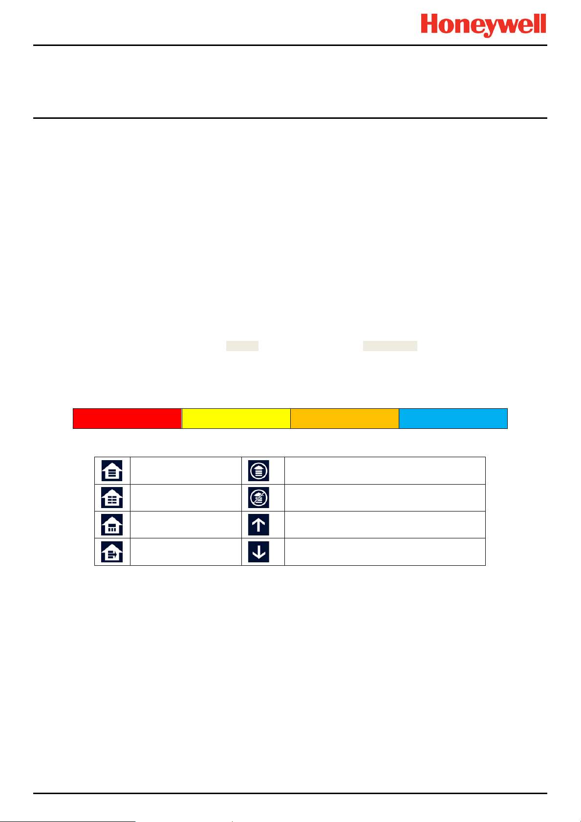
The icons in the navigation toolbar are used to toggle through the User Interface options, as shown in the tables below.
Scr
Icon
een
Glossary
Daily Operation
Functions)
for easy reference.
Alarm Event Fault Event Warning Event Inhibit Event
Channel List View
Channel Tile View
Channel Summary View
Output Channel List View
Table 7. Home Screen Icons
Notes:
• Flashing Colour – New Events
• Steady Colour – Acknowledged Events
• Channel List View – Display shows up to six inputs and events with automatic or manual scrolling.
• Channel Tile View – Display shows up to eight inputs and events.
• Channel Summary View – Display shows total counts for alarm 1, alarm 2, alarm 3, fault, warning and inhibits.
• Output Channel List View – Display shows up to eight outputs and events.
Events flash until acknowledged, and they stay coloured until the causative event is cleared / reset.
Touch any colour, channel or event if you want to see more information. You can also touch a filter icon (see below) to
show only items in that colour band, which is useful when you have multiple events demanding attention.
Manual Scrolling Toggle (the list and all events
can be manually scrolled)
Auto Scrolling Toggle (active events are locked
at the top of the list, other events scroll down)
Scroll the list up
Scroll the list down
MAN0996_Iss 1_02/16 Touchpoint Plus
Pt. No. 3011M5044_EN 27 User Guide
Page 36

Daily Operation
Alarm Filter
Fault Filter
Inhibit Filter
Warning Filter
Filter Information
Filter Refresh
Table 8. View Control Icons
Filters only show during active events but you can use them to instantly filter multiple events for clarity.
History Information
Alarm History
Fault History
Inhibit History
Warning History
Toggle View
MAN0996_Iss 1_02/16 Touchpoint Plus
Pt. No. 3011M5044_EN 28 User Guide
Page 37
Daily Operation
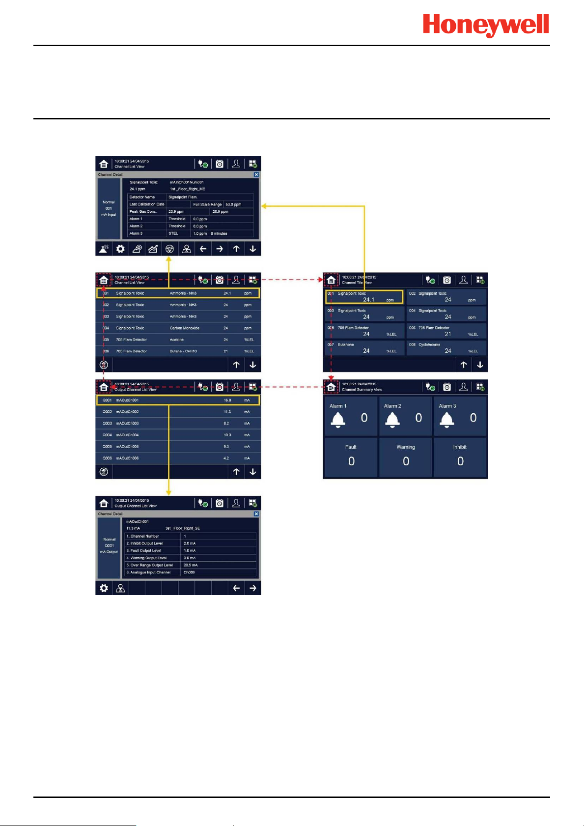
4.7.3 Navigating the Channel Detail Screens.
Touch an individual channel or item to display more details
Please see Ch12. Icon Glossary for further information.
:
MAN0996_Iss 1_02/16 Touchpoint Plus
Pt. No. 3011M5044_EN 29 User Guide
Page 38

Daily Operation
6.6.3 Navigation – Active
You can change the list type by touching a filter from one of the Tile views, and you can export the events to the SD card
by touching History>Export Event
Note: The History Information icon is the colour of the highest (uncleared) risk event.
Events and Filtering
MAN0996_Iss 1_02/16 Touchpoint Plus
Pt. No. 3011M5044_EN 30 User Guide
Page 39

4.7.4 Navigation – Menu
User must have the appropriate access level password to enter Maintenance, Configuration and System Test options.
Note: The system will log out after a defined period of inactivity.
(The default password authentication timeout is 15 (15 – 100) minutes and the Menu Timeout is 90 (5 – 100) seconds, but
these can be changed in Configuration>General>Timeout if required.)
Daily Operation
MAN0996_Iss 1_02/16 Touchpoint Plus
Pt. No. 3011M5044_EN 31 User Guide
Page 40
4.8 Responding to Alarms
4.8.1
View Active
Active alarms can be viewed:
1) At the Input screen, touch the red filter icon to display a list of the active Alarms, starting with the most recent event.
1) Unacknowledged alarms will flash; acknowledged ones will stay on.
2) Touch any alarm to view more information.
Note: The display will show the channel ID location tag and a high priority alarm level will be shown If more than one
alarm level has been triggered on the same channel.
Alarms
Daily Operation
4.8.2
Accept or Acknowledge
Always check that emergency evacuation and roll-call is completed before silencing the alarms.
To acknowledge an alarm, log in and press the button for >1 second, which will:
• silence the alarm
• stop the channels, LEDs and icons flashing
• acknowledge all active events except Faults
Note: Check for new alarms if the sounder restarts after you have acknowledged it.
Note: If a Relay Output channel has the Alarm Update function enabled, the alarm will be ignored for the Cause and
Effect matrix once it is acknowledged.
an Active
Alarm
MAN0996_Iss 1_02/16 Touchpoint Plus
Pt. No. 3011M5044_EN 32 User Guide
Page 41

4.8.3
Reset a Latched
A latched alarm is one that cannot automatically reset itself when the triggering event has cleared.
Note: Operator or higher access level is required
A latched alarm can be reset in three ways:
1) By logging in and pressing the button for >3 seconds. This will reset ALL latched alarms, faults and warnings,
2) By logging in and selecting Menu>Maintenance>Reset alarms/Faults. This will reset all latched events
3) By holding the Remote reset switch for >3 seconds. TPPL has the option of adding a remote acknowledge / reset
Daily Operation
Alarm
provided that the triggering event has cleared. It will also reset any latched relay outputs.
for the channel, provided that the input signal has returned to Normal status.
switch up to 500 m away from the Controller. The remote reset switch does not require a login so a key-lockable
switch should be used to prevent unauthorised access.
WARNING
A gas detector may indicate that the gas concentration in its vicinity has dropped to a safe level, but this does not
mean that a dangerous atmosphere doesn’t persist elsewhere in that area. Do not reset the alarms until the area
has been confirmed to be safe or has been adequately ventilated.
4.9
Event Information
4.9.1
Viewing Event
Detailed information about active events can be viewed in several ways:
• by touching the actual event to show detailed information about that channel.
• by touching one of the available filter icons on the bottom toolbar. The screen will then show a list of only the chosen
type of active events, and each event can be touched to show detailed information about that channel.
• by touching the icon to change the view layout (not all screens have filter icons).
Information
4.9.2 Accepting / Acknowledging Active Events
Note: Accept and Acknowledge have the same meaning in this context, but neither action will reset latched events.
Active events can be acknowledged by logging in and pressing the button for >1 second. This will acknowledge ALL
active events and the flashing will stop.
MAN0996_Iss 1_02/16 Touchpoint Plus
Pt. No. 3011M5044_EN 33 User Guide
Page 42

4.9.3
Resetting Latched Events
Note: Password access is required.
Acknowledged latched events can be reset in three ways:
1) By logging in and pressing the button for >3 seconds. This will reset ALL latched alarms, faults and warnings,
provided that the event has cleared. It will also reset any latched relay outputs.
2) By logging in and selecting Menu>Maintenance>Reset Alarms/Faults. This will reset all latched events,
provided that the input signal has returned to Normal / within tolerance.
3) By holding the Remote reset switch for >3 seconds. TPPL has the option of adding a remote acknowledge / reset
switch up to 500 m away from the Controller. The remote reset switch does not require a login so a key-lockable
switch should be used to prevent unauthorised access.
4.10
Inhibiting Channels
Note: Service or higher access level is required.
4.10.1 To Inhibit Input Channels:
1) Log in as Administrator or Service
2) Touch a channel, then touch the inhibit icon: and then touch [Yes]
3) Or use a Remote Inhibit input (key-locking) switch.
Daily Operation
4.10.2 To Clear Inhibits:
1) Log in as Administrator or Service
2) Touch an inhibited channel, th en touch the inhibit icon: and then touch [Yes]
Note: An auto-inhibit cannot be cleared manually. Auto-inhibits may occur during calibration or warm-up, when a
transmitter is signalling Inhibit, or when an Inhibit delay time is running.
4.10.3 To Change Inhibit Timeouts
1) Log in as Administrator or Service
2) Touch a channel, then touch the Settings icon:
3) Touch [Next] repeatedly until you reach page 7/7, as shown below:
4) Touch the chosen value, enter a new value, and touch [Finish]>[Finish]>[Apply]
Please see Ch12. Icon Glossary for further information.
MAN0996_Iss 1_02/16 Touchpoint Plus
Pt. No. 3011M5044_EN 34 User Guide
Page 43

4.11
Viewing Input Channels and Input
From the Input screen, toggle the icon between Channel Tile>Channel Summary>Channel Output.
1) From the Input screen, select Channel List or Channel Tile.
2) A list of all input channels is shown in order of channel ID. The channel ID, gas name, status, min/max peak gas
concentration and current reading will be shown.
3) The list can be filtered by status – Alarm, Fault, Inhibit, Warning or All.
4) Touch a channel and the Channel detail (left below) screen will appear. Depending on access level, a number of
options will be shown (see Ch.12 Icon Glossary for Icon names):
Daily Operation
Details
Function Icon Access Level Comment
Shows detailed information about the channel including Custom ID,
Channel Detail — Viewer
Calibration
Channel Settings
Peak reset
Trend / Plot
Inhibit
Channel location
Trend Graph
Service Option to calibrate the channe l .
Service Change the input channel settings.
Service Reset peak reading of the channel.
Viewer Shows the Trend / Plot.
Service
Viewer
Viewer
sensor and gas name, gas reading, configured alarms and alarm
levels.
Inhibits the channel. On an inhibited channel, this option is Clear
Inhibit. See Normal Operation, Inhibit for more information.
Shows the physical position of the I/O Module and channel (see
pictures above).
Shows the trend graph for the channel. See Normal Operation, View
Trend Graph for more information.
MAN0996_Iss 1_02/16 Touchpoint Plus
Pt. No. 3011M5044_EN 35 User Guide
Viewer Scroll Left, Right, Up, Down.
Page 44
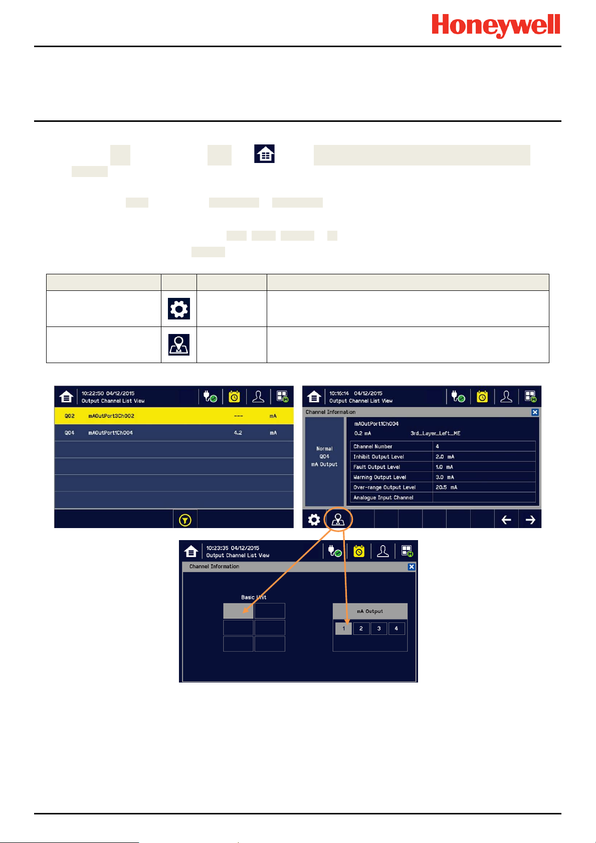
Daily Operation
4.12
Viewing Output
From the Input screen, toggle the Home icon between Channel Tile>Channel Summary>Channel
Output.
1) From the Input screen, select Channel List or Channel Tile.
2) A list of all output channels is shown in order of channel ID. The channel ID, location tag and status are shown.
3) The list can be filtered by status – Fault, Inhibit, Warning or All.
4) Touch a channel and the Channel detail screen will appear. Depending on access level, a number of options will be
shown:
Function Icon Access Level Comment
Channels
Channel configuration
Linked input Channel Nr.
Service
Viewer
Change the output channel configuratio ns: Inhibit, Fault, Warning,
and Over-range output level
Display an output channel number that is mapped to the terminal
number
MAN0996_Iss 1_02/16 Touchpoint Plus
Pt. No. 3011M5044_EN 36 User Guide
Page 45
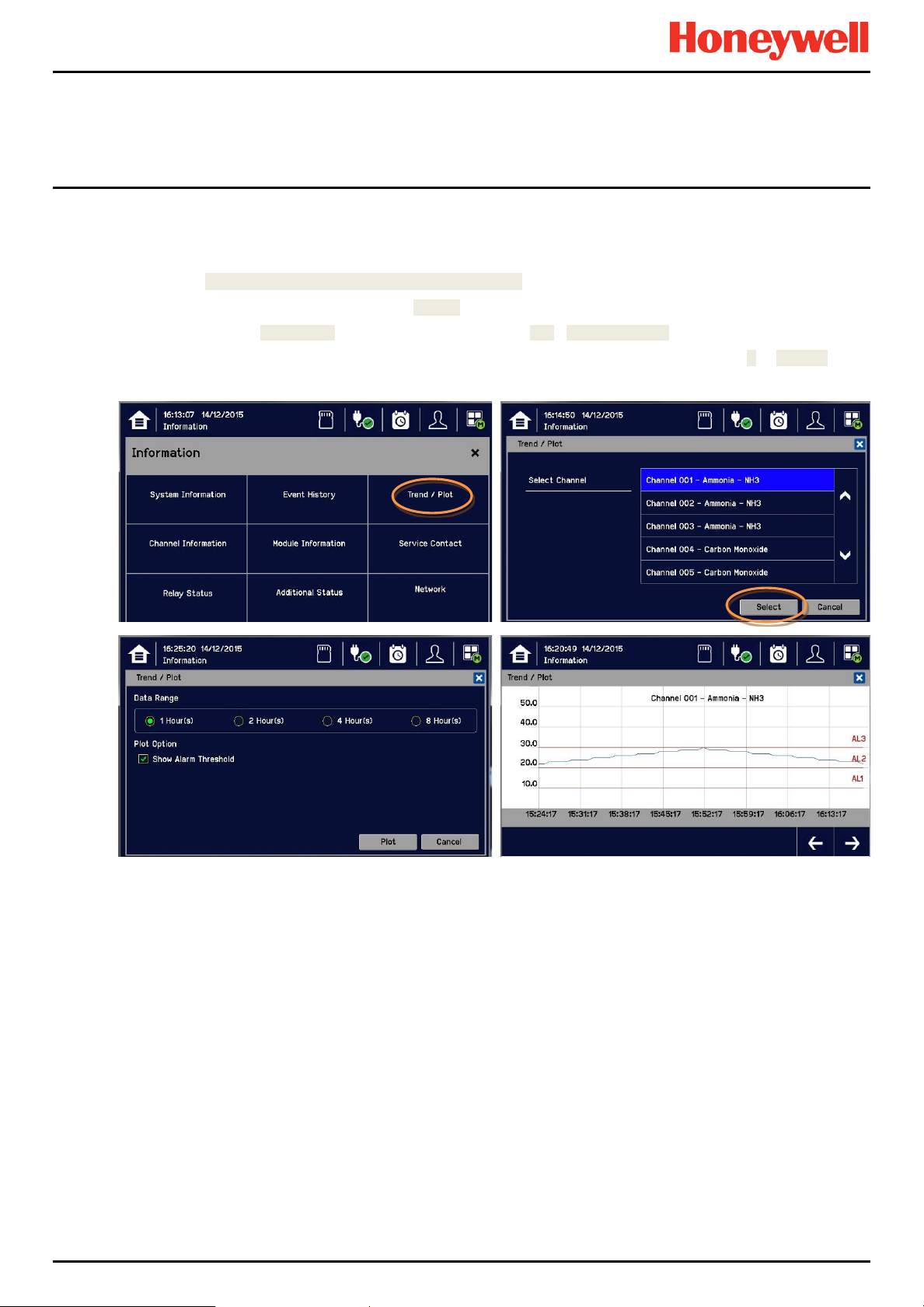
4.13
Viewing the Trend
The Trend graph is drawn using one minute average readings so it is not suited to viewing short-term signal fluctuations.
To view the graph:
1) Touch the Menu Icon>Information>Trend / Plot.
2) Touch the required channel, and then touch [Select].
3) Select the required Data Range (1/2/4/8 hours) and then touch Plot. (Alarm Threshold is shown by default.)
4) The trend graph will be displayed. Use the arrows to move backwards or forwards in time; use the X or [Cancel] to
exit.
Note: The Touchpoint Plus Trend / Plot will retain up to the latest 8 hours of data but will be cleared after a power reset.
Note: Touchpoint Plus does not adjust automatically for daylight savings time but it will retain a backup of the earlier data
if the system clock is backdated (e.g. when ending daylight savings time).
Daily Operation
Graph
MAN0996_Iss 1_02/16 Touchpoint Plus
Pt. No. 3011M5044_EN 37 User Guide
Page 46

Daily Operation
4.14 Viewing and Exporting Event History
The event history for the complete system can be viewed in date order (latest first). The history can be filtered by Alarm,
Fault, Inhibit, or Warning.
4.14.1 To View the Event History
Touch Menu>Information>Event History, then touch the Filter icon of choice or scroll through the list.
Note: Touchpoint Plus does not adjust automatically for daylight savings time so it will retain a backup of the earlier data if
the clock is backdated (e.g. when ending daylight savings time).
Event data is automatically saved to an installed SD card. The event history data can also be exported to the SD card on
demand.
4.14.2 To Export the Event History
First touch the SD Card icon to ensure that you have sufficient empty space on the SD card.
Touch Menu>Information>Event History. Select the event (use filters if there are too many shown) and touch
Export Event.
Note: Microsoft Excel 2003 is limited to a maximum of 65,526 entries. If the report is larger than this a ‘file not loaded
completely’ message may be generated. Microsoft Excel 2010 has a much larger capacity that should be sufficient for all
Touchpoint Plus generated reports.
Note: Touchpoint Plus does not adjust automatically for daylight savings time so TPPL will retain a backup of the earlier
data if the clock is backdated (i.e. when ending daylight savings time).
4.15 Accessing the System Information and Service Contact Details
Touch Menu>Information>System information to view details about the Firmware, Software and serial
numbers.
Touch Menu>Information>Service Contact or see the back page for details of how to access technical
support.
4.16 System State and System Failure Relays
The Main Module has three relays (30 VDC or 250 VAC, both 1.7 A):
• One or both System State relays can activate if there is any active alarm, fault, warning or inhibit in the system (if
configured).
• The System Failure relay can activate if the safety function of the system is not operating, for example due to a major
fault or power loss.
MAN0996_Iss 1_02/16 Touchpoint Plus
Pt. No. 3011M5044_EN 38 User Guide
Page 47

Daily Operation
4.17 Monitoring TPPL via the Optional Web Interface
You can view the TPPL status via an optional Web interface but you cannot currently control it remotely (due late 2016).
The following browsers are currently supported:
• Chrome
• IE10, IE11
• IE8, IE9 (Trend / Plot is not available)
• Safari
• Other browsers may work but their performance may vary.
Note: Please contact Honeywell Support (back page) if a browser security update causes performance issues.
Windows XP has known security issues and therefore must not be used with TPPL.
4.17.1 Web Interface Configuration
The Web Interface is an optional external PC interface tool that provides remote web clients with TPPL data in real time.
From late 2016 you will also be able to acknowledge, inhibit and reset I/O channels and remotely carry out calibration and
configuration.
The Web Interface supports two concurrent web clients but this does not prevent further users from accessing it, although
multiple users will degrade performance across all connected clients.
The TPPL Default IP address is 192.168.0.100, but this may have to be changed if you experience network conflicts or are
monitoring multiple TPPL systems. Please contact your Service Contact if you need help to do this.
The Web Interface show s the curren t TPPL status as follows:
• Channel List View – shows up to six inputs and events with automatic scrolling
• Channel Summary View – shows total counts for alarm 1, alarm 2, alarm 3, fault, warning and inhibits
• Channel Output View – shows up to eight outputs and events
Key to examples below:
• Channel marking in red – one or more input channels are in Alarm
• Channel marking in yellow – one or more channels are in Fault
• Channel marking in orange – one or more channels are in Inhibit
• Channel marking in blue – one or more channels are in Warning
CAUTION
MAN0996_Iss 1_02/16 Touchpoint Plus
Pt. No. 3011M5044_EN 39 User Guide
Page 48

Daily Operation
You can select how you monitor TPPL via the Web Interface menus (currently view only) by selecting from the menu:
Figure 14. Web Interface Channel List View
Figure 15. Web Interface Channel Summary View
Figure 16. Web Interface Connection Failed Dialog
MAN0996_Iss 1_02/16 Touchpoint Plus
Pt. No. 3011M5044_EN 40 User Guide
Page 49

4.17.2 Web Interface Navigation
The Web Interface menu allows you to see and monitor the following information:
• System Information
• Event History
• Trend / Plot (not IE8 or IE9)
• Channel Information
• Module Information
• Service Contact
• Relay Status
• Additional Status
• System Configuration
Figure 17. Web Interface Information Menu Showing Event History
Daily Operation
MAN0996_Iss 1_02/16 Touchpoint Plus
Pt. No. 3011M5044_EN 41 User Guide
Page 50

Daily Operation
This page deliberately blank.
MAN0996_Iss 1_02/16 Touchpoint Plus
Pt. No. 3011M5044_EN 42 User Guide
Page 51

Daily Operation
Chapter 5. Daily / Shift Checks
In most countries it is a legal requirement to keep itemised, time-stamped operations logs that must be made available to
the authorities in the event of a serious accident or incident, and the TPPL digitised event record alone may not satisfy
those requirements.
It is therefore recommended that each shift carries out a formal TPPL handover to the next shift. As a minimum, you
should check and record that:
• the enclosure door is correctly closed and se cure d to prevent tampering, electric shock or ex plosions.
• the Touchscreen is clean, unobstructed and undamaged.
• power and batteries are ok. To check, see and touch:
• the appropriate Channel LEDs are green.
• there are no alarms, inhibits, faults or warnings, and that any recent events are fully briefed and understood.
• there is sufficient SD Card storage space for the entire shift (see Note below). To check, touch:
• the Trend / Plot has restarted for the new shift. To confirm, touch
(Menu>Information>Trend/Plot>Channel>Select>Plot) for each relevant channel.
• there are no maintenance items due that day, e.g. weekly checks or tests, calibrations or sensor replacements.
• both shift leaders have signed the handover-takeover checklist.
You should rectify any issues in accordance with this manual or take alternative precautions before allowing any
hazardous work to proceed.
Note: You have to switch off and isolate power to change the SD card or batteries, so it is usually better done before shift
start as you may have to make alternative safety arrangements while TPPL is off-line. (There is a proposed modification to
shield the live terminals and remove the need for powering off in the future.)
Opening the enclosure exposes potentially lethal live terminals. Always ensure that all TPPL power is switched
off, isolated and allowed to dissipate before opening the enclosure. This includes external mains voltages routed
It is recommended that the enclosure is only opened by a qualified Service Technician and that it is kept closed
Ensure that alternative safety arrangements are in place, and ensure that Normal Operation
and secured during normal operation.
The Touchpoint Plus system is not operational while power is off.
is restored as soon as possible.
WARNING
through TPPL relays.
WARNING
MAN0996_Iss 1_02/16 Touchpoint Plus
Pt. No. 3011M5044_EN 43 User Guide
Page 52

Daily Operation
This page deliberately blank.
MAN0996_Iss 1_02/16 Touchpoint Plus
Pt. No. 3011M5044_EN 44 User Guide
Page 53

Maintenance
Chapter 6. Routine Maintenance and Scheduled Testing
This chapter describes how to perform common maintenance operations and system testing. The required frequency of
inspection and maintenance will depend on local site conditions and will need to be established through experience.
Please refer to IEC/EN 60079-29-2 or other local or national regulations for guidance on establishing an appropriate
maintenance routine.
Read Chapter 2 Safety and other related warnings and cautions before carrying out any work on the system.
If the relays are switching mains voltages, hazardous live terminals may be present within the
Relay Output Module even if the Touchpoint Plus system is isolated.
Ensure that all current is isolated and dissipated before touching live terminals.
WARNING
WARNING
6.1 Routine Maintenance
6.1.1 Weekly Checks
• Visually inspect all cables and conduits for loose connections, security of attachment, and signs of damage.
• Wipe the Touchpoint Plus Controller with a soft damp cloth or use PC Screen cleaner.
• Check for dust contamination.
• Periodically exercise the outputs (see the following chapters) to confirm their functionality (see Caution above).
Test outputs will be generated and relays will be activated during Cau se and Ef fe ct (C&E) Testing.
Ensure that relay activated output systems (i.e. emergency deluge / sirens etc.) are isolated before starting the
While an Operator could Force a channel, a Service password is requir ed to isolate services, carry out tests,
For these reasons Operators should carry out visual inspections and cleaning only, unless under the direct
Do not use solvent or abrasives to clean any part of the Touchpoint Plus System.
CAUTION
Relay and mA Output tests.
CAUTION
Clear Force, and restore the system to full o perat ion al stat u s .
supervision of the Service engineer.
CAUTION
Use only soft, lightly dampened cloths or proprietary screen cleaners.
MAN0996_Iss 1_02/16 Touchpoint Plus
Pt. No. 3011M5044_EN 45 User Guide
Page 54
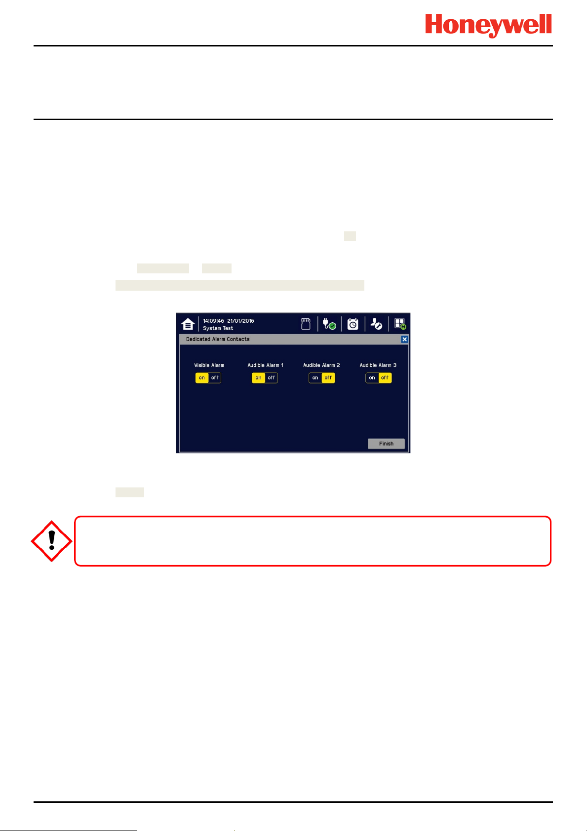
6.2 Routine Testing
It is normal practice to sound the site alarms weekly, both to check they work and to accustom personnel to the sound
they make.
As it involves isolating / inhibiting emergency sys tem s during testi ng, it migh t be more prudent to test the TPPL relays and
mA outputs only on a planned monthly basis.
Always have alternative safety arrangements in place and alert your personnel before and during testing.
6.2.1 Exercising the Audio/Visual Alarms
Audio/visual alarms can be tested by switching the Dedicated Alarms On. To do this:
1) Ensure that relay activated output systems (i.e. emergency deluge / sirens etc.) are isolated before starting the test.
2) Login as an Administrator or Service.
3) Touch Menu>System Test >Dedicated Alarm Contacts.
4) Touch the appropriate Alarm to toggle it on for each output (see below).
5) Check the alarm outputs are visible / audible and turn them off when satisfied.
6) Touch [Finish] when the tests are completed and all selections will automatically turn off.
Ensure that the system is returned to normal operation once testing is complet e.
Maintenance
CAUTION
MAN0996_Iss 1_02/16 Touchpoint Plus
Pt. No. 3011M5044_EN 46 User Guide
Page 55

6.2.2 Exercising the Relays
Ensure that all mains current is isolated and dissipated before touching live terminals.
Relay output channels can be tested by forcing the relays to an active state:
1) Ensure that relay activated output systems (i.e. emergency deluge / sirens etc.) are isolated before starting the test.
2) Login as an Administrator or Service.
3) Touch Menu>System Test>Force Relay.
4) Touch the active (yellow) Relay Output Channels to be tested, and toggle them on.
5) Check the selected relay output contact power switching using a suitable test tool or voltmeter.
6) Touch [Finish]>[Cancel] and all selections will turn off.
7) Proceed to the next step.
If the relays are switching mains voltages, hazardous live terminals may be present.
Maintenance
WARNING
6.2.3 Checking the mA Outputs
Milliamp (mA) output channels can be tested by forcing the mA output:
1) Ensure that relay activated output systems (i.e. emergency deluge / sirens etc.) are isolated before starting the test.
2) Login as an Administrator or Service.
3) Touch Menu>System Test>Force 4-20mA.
4) Touch the All radio button and check the mA output value; touch the mA box to change it. For single channels touch
the Single Channel number box and then scroll through the list and touch the required channel followed by [Select].
MAN0996_Iss 1_02/16 Touchpoint Plus
Pt. No. 3011M5044_EN 47 User Guide
Page 56
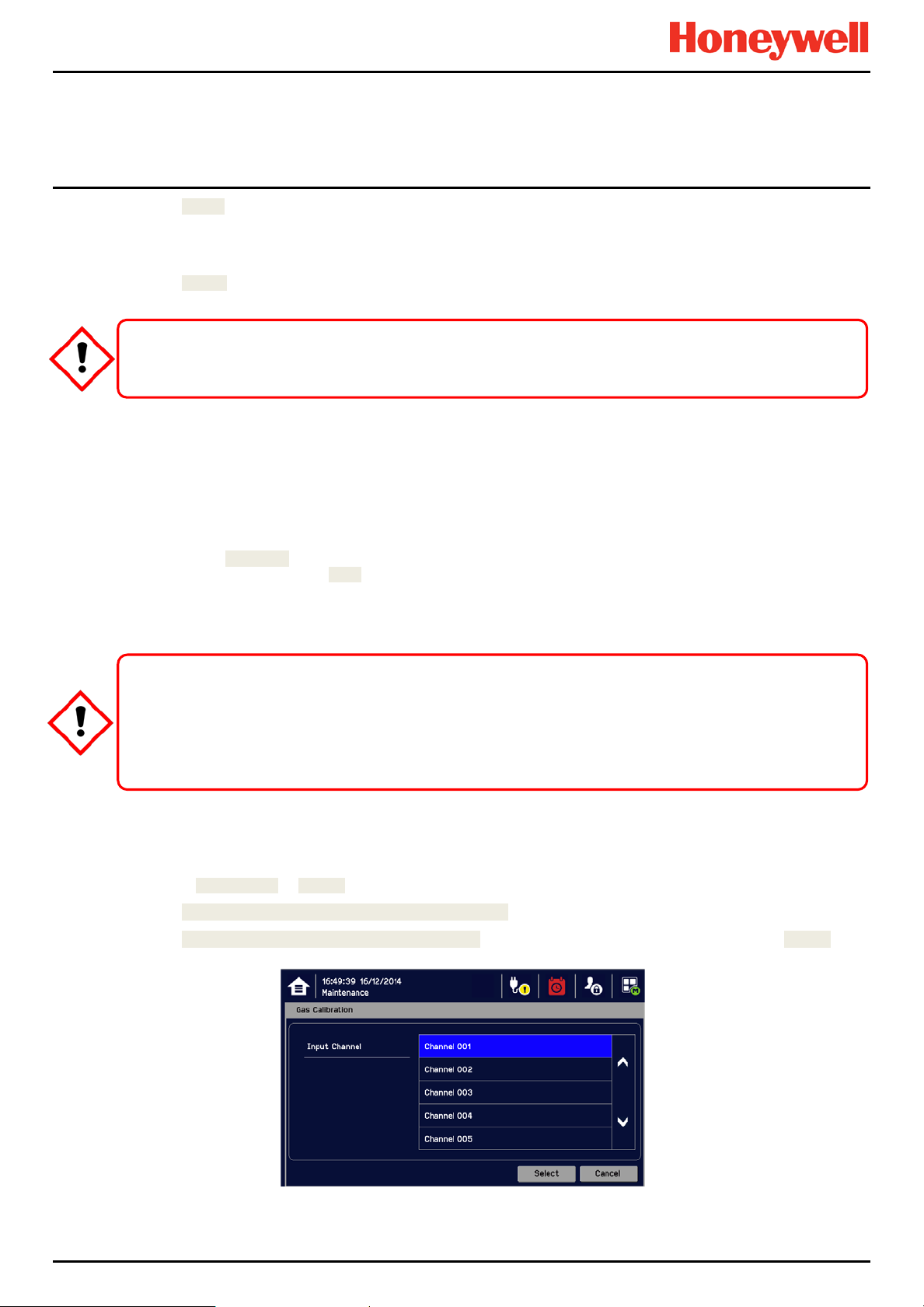
5) Touch [Apply].
hydrocarbon / air mix. Always follow the sensor manufacturer’s data sheet when cross-calibrating sensors.
6) Check the appropriate mA output levels using a suitable ammeter.
7) Repeat steps 4 to 6 for all mA output channels.
8) Touch [Finish] when the tests are completed.
Ensure that the system is returned to normal operation once testing is complete.
6.2.4 Calibrating mV Input Channels
Catalytic sensors should be calibrated periodically according to the manufacturer’s recommendations. This should be a
two-person job to avoid the controller timing out and losing the settings.
Note: To enable a calibration interval for the channel, edit the interval setting before starting calibration (see the TPPL
Technical Handbook or call your Service Contact).
You should select First Span only when calibrating a new or replacement sensor for the first time. You then adjust the mV
Baseline, and then you should use Span for all calibrations thereafter (see Note below).
Note: Adjustment of the Baseline is only required when a mV channel is configured for the first time or when a catalytic
bead element is replaced. Once the Baseline is established it should not be adjusted for second or subsequent gas
calibrations, i.e. until the next catalytic bead replacement.
For greater accuracy, catalytic gas detectors should be calibrated using a certified gas/air mixture
equal to 50 %LEL of the actual target gas being monitored. Always refer to the sensor technical manual for
If you cannot obtain an exact or certified span gas match you can carry out a ‘cross-calibration’ using a similar
Maintenance
CAUTION
CAUTION
detailed information.
To Calibrate a mV Input Channel:
1) Install or replace catalytic bead sensor elements according to their technical manual.
2) Login as Administrator or Service.
3) Touch Menu>Maintenance>Adjust mV Baseline and select a mV input channel.
4) Touch Menu>Maintenance>Gas Calibration. Touch the channel to be calibrated, followed by [Select]:
MAN0996_Iss 1_02/16 Touchpoint Plus
Pt. No. 3011M5044_EN 48 User Guide
Page 57

Maintenance
5) Select Zero Calibration, ch e ck or uncheck First Calibration, touch [Start] and apply clean air to the sensor:
6) View the reading until it is stable, and then touch [Apply].
7) Confirm that the gas reading is stable, and touch [Next].
8) Enter the concentration of the span gas and touch [Start]:
9) When ready touch [Start] and apply gas to the sensor.
10) View the reading until it is stable, and then touch [Apply]. This may take 3 – 5 minutes, depending on the gas type.
11) Confirm that the gas reading is correct.
12) Remove the span gas from the sensor, and confirm that the gas reading has returned to zero.
6.3 Periodic Scheduled Testing
Periodic Scheduled Testing should only be carried out by a Honeywell authorised technician or a qualified person trained
in accordance with the TPPL Technical Handbook. Apart from the safety considerations, Honeywell’s field service
technicians will be able to minimise downtime should a fault become apparent during testing.
MAN0996_Iss 1_02/16 Touchpoint Plus
Pt. No. 3011M5044_EN 49 User Guide
Page 58

Maintenance
This page deliberately blank.
MAN0996_Iss 1_02/16 Touchpoint Plus
Pt. No. 3011M5044_EN 50 User Guide
Page 59
Servicing
Chapter 7. Repairs, Replacements and U pgrades
With the exception of battery replacement, Repairs, Replacements and Upgrades should only be carried out by
authorised Honeywell technicians or by qualified persons trained in accordance with the TPPL Technical Handbook.
Failure to follow this advice will invalidate your warranty and may lead to death, injury, or irreparable damage.
7.1 Back up Battery Maintenance
Replace the battery pack only with Honeywell Analytics part no. TPPLSIBB and the PCB CMOS battery only
According to local laws and regulations the battery installed within your product should be disposed of separately
from household waste. When the battery reaches its end of life, take it to a collection point designated by local
Note: The DC 24 V battery pack has an integral 15 A over-current protection fuse, and will accept a nominal input charge
of 24 – 32 VDC. (<24 VDC will not charge the battery to the level required for backup power.)
Batteries shall only be fitted, removed or replaced in non-hazardous (safe) areas.
Lithium batteries may cause severe injury or death if put in the mouth or swallowed.
Always keep them away from children and dispose of them as hazardous waste.
Use of other batteries may present a risk of fire or explosion.
DANGER
with battery type CR2032.
DANGER
CAUTION
authorities.
7.1.1 Recommended Backup Battery Maintenance
Monthly a qualified electrical tradesperson should:
• Switch off and isolate TPPL power supplies.
• Visually inspect the Touchpoint Plus Battery and (as the enclosure is open) all internal cabling.
• Check for signs of damage, deterioration, leakage or loose connections.
• Check that the cooling vents have not become obstructed.
7.1.2 How to Replace the Backup Battery
The battery pack goes into sleep mode when it is disconnected or switched off. Connecting the battery pack to a power
source switches it to active mode and it will function normally after a short booster charge.
To replace the battery pack:
1) Ensure that the environment is safe and the atmosphere is below flammable levels.
MAN0996_Iss 1_02/16 Touchpoint Plus
Pt. No. 3011M5044_EN 51 User Guide
Touchpoint Plus shall not be operated with the access door unsecured when in Normal mode.
Failing to secure it properly will risk fire, explosion or electr i c sho ck, and will invalidate Regulatory Approval.
DANGER
Page 60
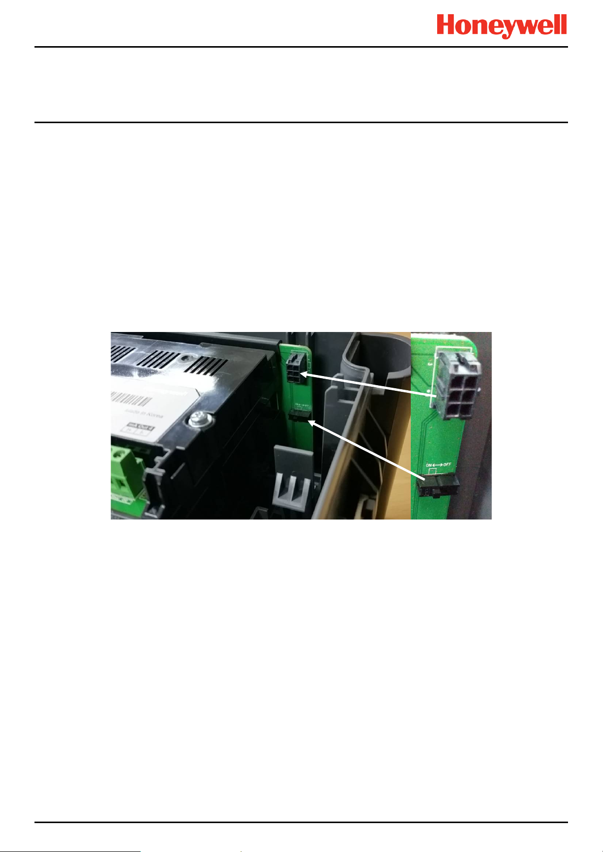
Servicing
2) Switch TPPL off and isolate its power supplies.
3) Unscrew the two locking handle security screws and open the enclosure.
4) Switch the backup battery On/Off switch to Off (Fig. 50) to protect the PCB from arcing/spiking when disconnecting /
reconnecting
5) Disconnect the battery connector from the PCB.
6) Replace the battery pack with Honeywell Analytics Part No. TPPLSIBB.
7) Reconnect the battery connector to the PCB.
8) Switch the backup battery On/Off switch back to On.
9) Close the enclosure door and secure the handle with the two security screws.
10) Switch power on and restore TPPL to normal operation.
11) Touch the power icon to check battery power levels.
Figure 18. Battery On/Off Switch and Battery Connector
Note: Ensure that the battery On/Off switch is in the On position before closing the access door or the backup battery will
not work when it is most required.
MAN0996_Iss 1_02/16 Touchpoint Plus
Pt. No. 3011M5044_EN 52 User Guide
Page 61

Troubleshooting
Chapter 8. Troubleshooting
Problems are signalled by an error code shown on the control panel display. The error is recorded in the event log and the
screen can be cancelled once the fault is corrected.
The error messages are explained in Ch.9. Fault Codes. Note the fault numbers / messages and check them in Ch. 9
before power-cycling the TPPL as they may be spurious / unreproducable following a system reboot.
Contact Honeywell Analytics Technical Support if an error appears repeatedly, if it cannot be cleared, or if it is not listed in
Ch.9. Fault Codes.
8.1 Calling for Technical Support.
Please contact Honeywell Analytics Technical Support if your problem cannot be resolved or if you need additional help.
You can find our contact details on the rear cover of this manual.
To assist the Honeywell Helpdesk in giving you technical support, it would be helpful to have the following information
ready:
• Your Company contact details and a contact name and department.
• The system model type, i.e. Touchpoint Plus, and its Serial Number and Part Number. These can be found on the
system identification label or under the System Information menu option.
• The software version found under the System Information menu option.
• Error messages and code numbers that were shown on the display screen.
• Details of the difficulty that you are experiencing.
• Status of the system (Inoperative, partially operative, still functioning etc.)
To assist with the fault diagnosis you may be asked to send a copy of your event log by email.
Read Chapter 2 Safety and other related warnings and cautions
before carrying out any work on the gas detection systems.
WARNING
MAN0996_Iss 1_02/16 Touchpoint Plus
Pt. No. 3011M5044_EN 53 User Guide
Page 62

Troubleshooting
Chapter 9. Fault Codes
Code Display in Event History Description
1
Communication fault [B/D Type], Pos: xx, Code: xxx Internal communication fault
2
Memory fault [B/D Type], Pos: xx, Code: xxx internal memor y fault
3
Catalogue memory fault Catalogue me mory corr upte d
4
Internal hardware fault [B/D Type], Pos: xx, Code: xxx Internal hardware fault
5
Sensor circuit fault CH: xx, [B/D Type], Pos: xx, Code: xxx Sensor circuit fault
6
Supplied voltage fault [B/D Type], Pos: xx, Code: xxx Supplied voltage fault
7
Internal software fault [B/D Type], Pos: xx, Code: xxx Internal software failure
8
— Reserved
9
Sensor fault CH: xx, [B/D Type], Pos: xx, Code: xx Sensor fault (including signal range fault)
10
11
12
13
14
15
16
17
mA Output Error CH: xx, [B/D Type], Pos: xx Analogue output mismatched
Relay Output Error CH: xx, [B/D Type], Pos: xx Relay not controlled
Detector In Fault CH: xx, [B/D Type], Pos: xx
Battery Fault Pos: xx Backup battery fault
IO B/D Not Matched [B/D Type], Pos: xx,
Prev: xxx, Current: xxx
Negative Reading CH: xx, [B/D Type], Pos: xx, Conc: xxxx
Fault Cleared CH: xx, [B/D Type], Pos: xx, Code: xx Fault self-cleared
Reset all faults Manually reset all faults
Remote fault notified by a detector
(depending on fault signal range)
I/O board not matched or present
Cell is producing a negative reading
(depending on gas under-range limit)
MAN0996_Iss 1_02/16 Touchpoint Plus
Pt. No. 3011M5044_EN 54 User Guide
Page 63

Specifications
Chapter 10. Technical Specifications
10.1 Environmental
Sealed enclosures are rated IP65 NEMA 4x, and can be installed indoors only in a Pollution Degree 2, 10 to 95 %RH NonCondensing environment that affords total protection from rain, snow and direct sunlight.
Operating Temperature
Storage Temperature
Operating Humidity (closed)
10.2 User Interface and Main Module
LCD Touch Screen Type
Front Display
Communication Outputs
Output Relays
Dedicated Audio and Visual alarm
Remote Terminals Optional remote acknowledge, reset and inhibit
-10 °C to + 55 °C
-25 °C to + 60 °C
10 to 90 %RH (non-condensing)
7’ TFT Colour LCD with LED Backlight (resistive touch screen)
800 x 480 pixels (WVGA) Resolution
Active area 155.08 mm (H) x 86.92 mm (V)
Green Power LED
Red Alarm LED
Yellow Fault/inhibit LED
Alarm Mute /Reset Push Button
Alarm Buzzer (Sound Level: 70 dB at 1 m)
1) 10/100 Mbps Ethernet Interface with standard RJ-45 connector
2) RS-485 Modbus connections supporting 115.2 kbps max.
Two configurable and one fixed System State Relays:
1.7 A @ 250 VAC, 1.7 A @ 30 VDC (non-inductive load)
Four outputs to external devices
Supply voltage Vs (18 – 32 VDC) –1.8* VDC (max), max 300 mA
per channel
*Voltage drop at ambient temperature
10.3 External Power Supplies
SMPS Power Supply
AC Input Voltage Range (~)
DC Input Voltage Range (—)
Input Frequency Range (~)
Output Voltage (—)
Dimension
MAN0996_Iss 1_02/16 Touchpoint Plus
Pt. No. 3011M5044_EN 55 User Guide
156 W
AC 110/220 V ±10 % of nominal (manual switching)
DC 18 – 32 V SELV Supply
AC 50 – 60 Hz ± 6 %
DC 24 V
199 x 98 x 38mm (L x W x H)
Page 64

10.4 Backup Battery
Specifications
Description
Electrical Connection
Dimensions/Weight
Operating Temperature
Operating Humidity
Storage Life Limitations
Storage Lifetime without re-charge
Input Current (charging) (—)
Output Voltage (when supplying) (—)
Maximum Input Current
Maximum Output Current
Current Limit Protection
10.5 Wall Mount Enclosure
Material
Cable Gland Plug
Environmental Protection
Operating Humidity
Mounting Bracket
Enclosure Weight
Dimension
22.2 V Lithium - ion Battery, 2600mAh
6 X 3.7 VDC in series
124.8 x 78.9 x 29.2 mm, 425g
0 – 50 °C
10 to 90% RH (non-condensing)
1 Year: –20 °C to +25 °C (–4 °F to +077 °F)
3 months: –20 °C to +45 °C (–4 °F to +113 °F)
1 month: –20 °C to +60 °C (–4 °F to +140 °F)
1 year
DC 24 – 32 V @ 0.38 mA max.
17.4 – 25.2 VDC
250 mA
5 A
FUSE 15 A (non-replaceable)
PC ABS
PG16
IP65 (when fully closed and locked), NEMA 4x indoors
10 to 90 %RH (non-condensing)
W 423 x D 325 x H 16.5 mm – 1.5 Kg (approx.)
8.5 Kg (approx)
426 mm x 300 mm x 156 mm (16.9 ins x 11.8 ins x 6.2 ins)
MAN0996_Iss 1_02/16 Touchpoint Plus
Pt. No. 3011M5044_EN 56 User Guide
Page 65

Certification
WARNING
métrologique suivant la directive ATEX.
WARNING
dûment approuvés.
Chapter 11. Certifications
11.1 EC Declaration of Conformity
A full EC declaration of conformity is available on either original hardcopy or electronic file (Honeywell Analytics website).
This document lists the European Standards with which Touchpoint Plus complies.
Only the combustible gas detection portion of this instrument has been assessed for performance in
Seulement la partie détection de gaz explosif de cet équipement a fait l’objet de tests de performance
CSA performance is only valid when TPPL is connected to Honeywell Model MPD or 705 Catalytic Gas
La performance en conformité avec la CSA est valide uniquement lorsque l’appareil est connecté aux
détecteurs de gaz catalytiques Honeywell modèle MPD ou 705, ou à des détecteurs de gaz 4 – 20 mA
Detectors, or suitably approved 4 – 20 mA Gas Detectors.
accordance with the ATEX Directi ve.
AVERTISSEMENT
AVERTISSEMENT
MAN0996_Iss 1_02/16 Touchpoint Plus
Pt. No. 3011M5044_EN 57 User Guide
Page 66

Certification
WARNING
température
11.2 National and International Certificates of Compliance
The Touchpoint Plus Process Control Equipment holds the following National and International Certificates and
Certification Codes:
Title Standards Certificates
Hazardous Locations
(Non-Incendive)
Ordinary Locations /
Electrical Safety
Ingression protection IP65 and NEMA 4X —
EMC/RFI EMC Directive (EN 50270:2015) —
Battery Pack
Performance ISA 12.13.01 and CSA C22.2 No.152 UL File E466771
Copies of the certificates are available on request.
Note 1: OEMs are responsible for ensuring that their systems are certified in accordance with these tables and any 3rd-
party requirements.
Température ambiante : elle dépend des composants assemblés, vérifier individuellement les plages de
Ambient temperature: Dependent on components fitted, check individual rating plates.
Class 1, Division 2, Groups A,B,C,D, Temp. Code T4
ISA 12.12.01-2013
CSA C22.2 No. 213-M1987
UL/IEC/EN 61010-1, UL 508
CSA C22.2 No.61010-1/No.142
UN 38.3 (IEC 62133), UL 2054, UL 60950-1
CSA C22.2 No.60950-1-07
AVERTISSEMENT
UL File E477917
UL File E466771
UL File E470577
UL File MH60522
MAN0996_Iss 1_02/16 Touchpoint Plus
Pt. No. 3011M5044_EN 58 User Guide
Page 67

Icon Glossary
Chapter 12. Icon Glossary
#
1
2
3
4
5
6
7
8
9
10
11
12
Icon Description
Summary View Alarm
Summary View Normal
Summary View
List View
Tile View
Output View
Information Menu
Event History Information
Event History Alarm
Event History Fault
Event History Inhibit
Event History Warning
#
28
29
30
31
32
33
34
35
36
37
38
39
Icon Description
Trend Graph
Processing Ok
Processing Failed
Cancel
Scroll Start
Scroll Stop
List Up
List Down
Move Up
Move Down
Move Left
Move Right
13
14
15
16
17
18
19
20
21
22
23
24
25
No One Logged In
Operator Logged In
Service Logged In
Administrator Logged In
Menu Select
Mains Power On
Mains Off, Batteries On
SD Card Good
SD Card Not Good
Alarm Filter
Fault Filter
Inhibit Filter
Warning Filter
40
41
42
43
44
45
46
47
48
49
50
51
52
Maintenance Menu
System Setting Menu
Configuration Menu
Configuration
Calibration
Inhibit
Channel Location
Base Line Adjust
Peak Reset
Trend
Alarm Pop Up
Error Pop Up
Fault Pop Up
26
27
MAN0996_Iss 1_02/16 Touchpoint Plus
Pt. No. 3011M5044_EN 59 User Guide
Filter Information
Filter Refresh
53
54
Inhibit Pop Up
Warning Pop Up
Page 68

Icon Glossary
#
55
56
57
Icon Description
Battery Warning
Battery Critical
Power Off
#
58
Icon Description
Gas Calibration
MAN0996_Iss 1_02/16 Touchpoint Plus
Pt. No. 3011M5044_EN 60 User Guide
Page 69

List of Figures and Tables
Chapter 13. List of Figures
Figure 1. Quick Start Guide Label (Not to Scale) 8
Figure 2. Rating Label (External – Not Shown Below) 8
Figure 3. Protective Earth (Ground) Point 8
Figure 4. Equipment Earth (Ground) Point 8
Figure 5. Internal Label Positions 8
Figure 6. Touchpoint Plus Wall-Mounted Controller 13
Figure 7. Typical Installation Options 13
Figure 8. TPPL Controller Exploded View 14
Figure 9. Undoing the Two Security Screws and Opening the Enclosure 15
Figure 10. Controller Unit Layout Before Installation 18
Figure 11. Expansion Unit Layout Before Installation 19
Figure 12. Backplane DIP Switch Settings 19
Figure 13. Touchpoint Plus Controller User Interface 21
Figure 14. Web Interface Channe l List View 40
Figure 15. Web Interface Channe l Summary View 40
Figure 16. Web Interface Connection Failed Dialog 40
Figure 17. Web Interface Information Menu Showing Event History 41
Figure 18. Battery On/Off Switch and Battery Connector 52
Chapter 14. List of Tables
Table 1. Power Supply (SMPS RS–150–24) Electrical Ratings 16
Table 2. Maximum Power Consumption Calculations 16
Table 3. System Weights 17
Table 4. System Dimensions 17
Table 5. Home Screen Menu Icons 22
Table 6. User / Component Matrix 25
Table 7. Home Screen Icons 27
Table 8. View Control Icons 28
MAN0996_Iss 1_02/16 Touchpoint Plus
Pt. No. 3011M5044_EN 61 User Guide
Page 70

Please Note:
contract.
Issue 1_02/2016
While every effort has been made to ens ure accuracy in this
publication, no responsibility can be accepted for errors or
omissions. Data and legislation may change and you are
strongly advised to obtain copies of the most recently
issued regulations, standards and guidelines.
This publication is not intended to form the basis of a
H_MAN0996_EMEA
3011M5044 HAA160009
© 2015 Honeywell Analytics
 Loading...