

Page 1
Technical Handbook
Touchpoint Plus
i
Page 2

Revision History
Revision Comment Date
Issue 01 First Issue and initial translations 30/05/2015
Issue 02 Added new chapters, new data and final translations 09/06/2015
ii
Page 3

Disclaimer
In no event shall Honeywell be liable for any damages or injury of any nature or kind, no matter how caused,
that arise from the use of the equipment referred to in this manual.
Strict compliance with the safety procedures set out and referred to in this manual, and extreme care in the
use of the equipment, are essential to avoid or minimize the chance of personal injury or damage to the
equipment.
The information, figures, illustrations, tables, specifications, and schematics contained in this manual are
believed to be correct and accurate as at the date of publication or revision. However, no representation or
warranty with respect to such correctness or accuracy is given or implied and Honeywell will not, under any
circumstances, be liable to any person or corporation for any loss or damages incurred in connection with the
use of this manual.
The information, figures, illustrations, tables, specifications, and schematics contained in this manual are
subject to change without notice.
Unauthorized modifications to the gas detection system or its installation are not permitted, as these may give
rise to unacceptable health and safety hazards.
Any software forming part of this equipment should be used only for the purposes for which Honeywell
supplied it. The user shall undertake no changes, modifications, conversions, translations into another
computer language, or copies (except for a necessary backup copy).
In no event shall Honeywell be liable for any equipment malfunction or damages whatsoever, including
(without limitation) incidental, direct, indirect, special, and consequential damages, damages for loss of
business profits, business interruption, loss of business information, or other pecuniary loss, resulting from
any violation of the above prohibitions.
Warranty
Honeywell Analytics warrants the Touchpoint Plus system against defective parts and workmanship, and will
repair or (at its discretion) replace any components that are or may become defective under proper usage
within 12 months from the date of commissioning by a Honeywell Analytics approved representative* or 18
months from shipment from Honeywell Analytics, whichever is sooner.
This warranty does not cover consumable, batteries, fuses, normal wear and tear, or damage caused by
accident, abuse, improper installation, unauthorized use, modification or repair, ambient environment,
poisons, contaminants or abnormal operating conditions.
This warranty does not apply to sensors or components that are covered under separate warranties, or to any
3rd-party cables and components.
Any claim under the Honeywell Analytics Product Warranty must be made within the warranty period and as
soon as reasonably practicable after a defect is discovered. Please contact your local Honeywell Analytics
Service representative to register your claim.
This is a summary. For full warranty terms please refer to the Honeywell Analytics” General Statement of
Limited Product Warranty, which is available on request.
* A Honeywell Analytics approved representative is a qualified person trained or employed by Honeywell
Analytics, or a qualified person trained in accordance with this manual.
Copyright Notice
Microsoft, MS and MS–DOS are registered trademarks of Microsoft Corp.
Other brand and product names mentioned in this manual may be trademarks or registered trademarks of
their respective companies and are the sole property of their respective holders.
Honeywell is the registered trademark of Honeywell Automation and Control Systems (ACS).
Touchpoint is a registered trademark of Honeywell Analytics (HA).
Find out more at www.honeywellanalytics.com
iii
Page 4

MAN0984_Iss 2_06/15 Touchpoint Plus
Technical Handbook
Contents
Chapter 1 – Important Safety Information ............................................................................ 1
1.1 Cautions................................................................................................................................. 3
1.1.1 Intended Readers .......................................................................................................... 3
1.1.2 Conventions Used ......................................................................................................... 4
1.1.3 Associated Manuals ....................................................................................................... 4
Chapter 2 – Safety Hazards, Warnings and Cautions ......................................................... 5
2.1 Safety ..................................................................................................................................... 5
2.1.1 Warnings and Cautions .................................................................................................. 5
2.1.2 Safety Hazards .............................................................................................................. 6
2.2 Location and Descri pt ion of War ning Labels ....................................................................... 8
2.2.1 Safety Warning Labels ................................................................................................... 8
2.3 Electrical Hazards.................................................................................................................. 9
2.3.1 General Precautions ...................................................................................................... 9
2.3.2 Component Testing and Replacement ........................................................................... 9
2.3.3 Antistatic Precautions .................................................................................................. 10
2.3.4 Good Practice .............................................................................................................. 10
2.3.5 Lithium Battery Hazard ................................................................................................ 10
2.4 Product Com pliance ............................................................................................................ 11
2.5 Condit ions of Use ................................................................................................................ 12
2.5.1 Training of Personnel ................................................................................................... 12
2.5.2 Conditions Satisfying Local, National and International Safety Regulations ................... 12
2.5.3 Due Authorisation ........................................................................................................ 12
2.5.4 Approved Maintenance and Servicing Procedures ....................................................... 12
Chapter 3 – System General Description ........................................................................... 13
3.1 Equipment Specification ..................................................................................................... 15
3.1.1 Power Requirements ................................................................................................... 15
3.1.2 Weights ....................................................................................................................... 16
3.1.3 Dimensions ................................................................................................................. 16
3.1.4 Ambient Operating Temperature .................................................................................. 16
3.1.5 Overall Ambient Operating Humidity ............................................................................ 16
3.1.6 Storage Conditions (Without batteries) ......................................................................... 16
3.1.7 Storage Conditions (With batteries) .............................................................................. 16
3.1.8 IP Rating ..................................................................................................................... 16
3.1.9 Construction ................................................................................................................ 16
3.1.10 Touchpoint Plus Packaging ........................................................................................ 17
3.1.11 Packaging Components for Return to Manufacturer ................................................... 17
3.1.12 Disposal (WEEE Directive) ........................................................................................ 17
3.2 System Construction........................................................................................................... 17
Chapter 4 – System Mechanical Installation ...................................................................... 18
4.1 How to O pe n a nd Close the Enclosure ............................................................................... 19
4.2 Wa ll Mounting Requirements .............................................................................................. 20
4.2.1 Wall Mount Fixings ...................................................................................................... 21
Chapter 5 – Electrical Power Connection and Interfacing ................................................ 22
5.1 Powe r Connection ............................................................................................................... 22
5.1.1 AC Power Supply ........................................................................................................ 23
5.1.2 DC Power Supply ........................................................................................................ 24
5.1.3 Backup Battery Pack ................................................................................................... 24
5.2 Cabli ng Requirem e nt s ......................................................................................................... 25
5.2.1 AC Mains Voltage Power Cables ................................................................................. 25
5.2.2 DC Power Cables ........................................................................................................ 25
5.2.3 Field Device Cables ..................................................................................................... 25
5.2.4 Optional Expansion Unit Connection (available late 2015) ............................................ 26
5.2.5 Main Module Connections............................................................................................ 27
5.2.6 mA Input Module Connections ..................................................................................... 29
5.2.7 mV Input Module Connections ..................................................................................... 33
5.2.8 mA Output Module Connections (each) ........................................................................ 34
iv
Page 5

MAN0984_Iss 2_06/15 Touchpoint Plus
Technical Handbook
Contents
5.2.9 Relay Output Module Connections ............................................................................... 35
Chapter 6 – Touchpoi nt Plus Operating Instructions ....................................................... 37
6.1 User Interface General ........................................................................................................ 37
6.2 Menu Items and Access Levels .......................................................................................... 38
6.3 Touchscreen (Colour Resistive) ......................................................................................... 40
6.4 SD Card ................................................................................................................................ 40
6.5 Norm a l O pe ration (Safety
6.6 Overview –
6.6.1 User Interface
6.6.2 Navigation – Inputs and Outputs
6.6.3 Navigation – Active
6.6.4 Navigation – Menu ...................................................................................................... 44
6.6.5 Navigation – Active Access Level Icons ....................................................................... 45
6.7 Alarms
6.7.1 View active
6.7.2 Acknowledge
6.7.3 Reset a latched
6.8 Faults and W
6.8.1 View Faults and W
6.8.2 Acknowledging an Active Fault or Warning................................................................... 47
6.8.3 Reset a Latched Fault or
6.9 Inhibit ................................................................................................................................... 47
6.10 Viewing Input Channels and Input
6.11 Viewing Output
6.12 Viewing the Trend
6.13 To Vie w E v e nt His t ory and Export .................................................................................... 50
6.14 Checkin g t he Ca pa city of the S D Ca rd ............................................................................. 50
6.15 Accessing the System Information and Service Contact Details .................................... 50
6.16 System State Relays .......................................................................................................... 50
Touchscreen Interface
................................................................................................................................ 45
alarms
arnings
Channels
Functions)
Scr
een ................................................................................................. 41
Events and Filtering
..................................................................................................... 45
an active
alarm
......................................................................................................... 46
Graph
alarm
................................................................................................. 46
arnings
Warning
............................................................................................... 49
................................................................................................ 49
............................................................................... 41
.................................................................................. 41
Screens
.................................................................................. 45
......................................................................................... 46
Details
.................................................................. 42
.................................................................... 43
............................................................................. 47
................................................................... 48
Chapter 7 – Commissioning ................................................................................................ 51
7.1 Introduction ......................................................................................................................... 51
7.2 First Time Switch On ........................................................................................................... 51
7.3 Date, Time and
7.3.1 How to Set or Change Date, Time and Language Settings: .......................................... 52
7.4 Progr a m P a s s w ords ............................................................................................................ 52
7.5 Commission Input / O ut put Modules .................................................................................. 53
7.6 Channel Configurat ion ........................................................................................................ 53
7.6.1 Introduction ................................................................................................................. 53
7.6.2 Configuring a Channel (mA input and mV input channel) .............................................. 54
7.6.3 Editing a Configured Channel ...................................................................................... 55
7.6.4 Editing mA Input Channel Settings (In Pictures) ........................................................... 55
7.6.5 Editing mV Input Channel Settings (In Pictures) ........................................................... 56
7.6.6 Editing Relay Output Channel Settings ........................................................................ 57
7.6.7 Editing Relay Output Channel Settings (In Pictures) ..................................................... 58
7.7 Data Logging ....................................................................................................................... 59
7.8 Touch Pa ne l Configurat ion ................................................................................................. 59
7.8.1 How to Calibrate the Touch Panel ................................................................................ 59
7.9 Serv ic e Cont a c t S e t t ings ..................................................................................................... 60
7.10 Back up Configuration ...................................................................................................... 60
7.11 Calibrating mV Input C ha nnels ......................................................................................... 61
7.11.1 Adjusting the mV Sensor Baseline ............................................................................. 61
7.11.2 Calibrating a mV Sensor Channel .............................................................................. 61
Language Settings
................................................................................. 52
v
Page 6

MAN0984_Iss 2_06/15 Touchpoint Plus
Technical Handbook
Contents
7.12 Calibrat e mA input channel loops .................................................................................... 62
Chapter 8 – Maintenance ..................................................................................................... 63
8.1 Routine Ma intenance........................................................................................................... 63
8.1.1 Weekly Checks ............................................................................................................ 63
8.1.4 Exercising the Audio/Visual Alarm ................................................................................ 64
8.2 Test ing t he Touchpoint P lus S y s t e m.................................................................................. 65
8.2.1 Introduction ................................................................................................................. 65
8.2.2 Field Inputs Test .......................................................................................................... 65
8.2.3 Cause and Effect Test ................................................................................................. 66
8.3 How to Replac e a Fa ulty I/O Mod ule ................................................................................... 67
8.4 How to Add a New I/O Module............................................................................................. 68
8.5 How to Decom m is sion and Remove an I/O Module ........................................................... 68
8.6 How to Upda t e t he S e nsor Catalogue ................................................................................. 69
8.7 How to Ba c k up / Restore c onf iguration.............................................................................. 69
8.8 How to Upda t e Firmware ..................................................................................................... 70
8.8.1 How to Check System Compatibility ............................................................................. 70
8.8.2 How to Update the Firmware........................................................................................ 70
8.9 How to Cha nge the SD Car d ............................................................................................... 71
8.10 How t o Ca librate mV Input Channels ................................................................................ 72
8.11 Back up Bat t e ry Maintena nc e ........................................................................................... 74
8.11.1 Recommended Scheduled Maintenance .................................................................... 74
8.11.2 How to Replace the Battery Pack ............................................................................... 74
8.12 Ret urn to Factory De f a ult S e t t ings ................................................................................... 75
Chapter 9 – Troubleshooting .............................................................................................. 76
9.1 Calli ng f or Technic a l S upport. ............................................................................................ 76
Chapter 10 – Technical Specifications ............................................................................... 77
10.1 Env ironmental ................................................................................................................... 77
10.2 Use r Interfac e a nd Ma in Module ....................................................................................... 77
10.3 I/ O Module s ........................................................................................................................ 78
10.3.1 mA Input Module ....................................................................................................... 78
10.3.2 mV Input Module ....................................................................................................... 78
10.3.3 mA Output Module ..................................................................................................... 78
10.3.4 Relay Output Module ................................................................................................. 79
10.4 Pow e r Supplies .................................................................................................................. 79
10.4.1 External Supplies ....................................................................................................... 79
10.4.2 Backup Battery .......................................................................................................... 79
10.5 Enclosures ......................................................................................................................... 80
10.5.1 Wall Mount Enclosure ................................................................................................ 80
Chapter 11 – Certifications .................................................................................................. 81
11.1 EC de c laration of co nf ormity ............................................................................................ 81
11.2 Nat ional and Internationa l Ce rtificates of Complia nc e .................................................... 81
Chapter 12 – Replacement Parts and Optional Extras ...................................................... 82
Chapter 13 – TPPL Configuration Information .................................................................. 83
Chapter 14 – Glossary of Icons ........................................................................................... 84
Chapter 15 – Compatible Sensors ...................................................................................... 86
Chapter 16 – Configurable Parameter Reference Guide ................................................... 87
Chapter 17 – Fault Codes .................................................................................................... 90
Chapter 18 – List of Figu r es ................................................................................................ 91
Chapter 19 – List of Tables .................................................................................................. 92
vi
Page 7
MAN0984_Iss 2_06/15 Touchpoint Plus
ONLY. READ AND UNDERSTAND THE INSTRUCTION MANUAL COMPLETELY BEFORE
Technical Handbook
Important Safety Information
Chapter 1 – Important Safety Information
The Equipment referred to in this manual contains components and assemblies that are each certified for use
in a variety of differing environments, and it is the site owner’s responsibility to confirm the suitability of the
equipment prior to its installation and use.
The Equipment assemblies referred to in this manual are collectively certified for use in a flammable gas
detection system only. Any other use is not currently certified and is not authorized by the manufacturer.
Please check the product rating plate and look for the following marks to ensure that the supplied equipment
is suitable for its intended location and purpose:
Products bearing the CE mark conform to all applicable European Directives as stated on the Honeywell
product specific EC Declaration of Conformity.
Products bearing the UL mark conform to the requirements for Ordinary Locations. The letters C and US
mean that the product is certified for use in Canada and the United States of America.
FOR SAFETY REASONS THIS EQUIPMENT MUST BE OPERATED BY QUALIFIED PERSONNEL
OPERATING OR SERVICING THE EQUIPMENT.
POUR DES RAISONS DE SÉCURITÉ, CET ÉQUIPEMENT DOIT ÊTRE UTILISÉ, ENTRETENU ET
RÉPARÉ UNIQUE MENT PAR UN PERSON NEL Q UALIF IÉ. ÉTU DIER LE MANUEL D’INSTRUCTIONS
EN ENTIER AVANT D’UTILISER, D’ENTRETENIR OU DE RÉPARER L’ÉQUIPEMENT.
WARNING
ATTENTION
1
Page 8

MAN0984_Iss 2_06/15 Touchpoint Plus
WARNINGS
company regulations, and suitable for the installation. Additionally, cabling must satisfy
Technical Handbook
Important Safety Information
1) The equipment specified in this manual is only to be installed by the Manufacturer’s trained
personnel, or by competent persons trained in accordance with the Manufacturer’s installation
instructions.
2) Installation must be in accordance with the recognized standards of the appropriate authority in the
country concerned. Refer to local, national and company regulations.
3) Do not operate the Touchpoint Plus system or its components outside of their rated operating
specification.
4) Touchpoint Plus must not be operated in Oxygen enriched atmospheres, i.e. greater than 25% v/v
Oxygen.
5) All equipment containing a User Interface must be suitably protected from direct sunlight and rain.
6) Power Supply Fluctuations are not to exceed DC 18 – 32 V SELV Supply or ±10 % of nominal.
7) All versions of Enclosure apparatus are electrical Class 1, and must be connected to Protective
Earth (Ground).
8) The Touchpoint Plus installation must include a means of isolating or disconnecting the input
voltage supply. The isolation or disconnection device must be conveniently located close to the
system and be clearly labelled. For an AC mains voltage supply, the isolation or disconnection
device must disconnect both the line and neutr al poles, but maintain earth (ground) continuity.
9) The Touchpoint Plus input voltage supply must include over-cu rrent protec tion.
10) All cabling must be appropriately rated and approved in accordance with local, national and
requirements defined in the manuals of connected field devices, in particular if the field device is
certified for use in a hazardous location.
11) All signal cables and interconnections must be shielded and the shields terminated only at the
unified earth (ground) bus bar situated inside the enclosure
12) All conduits and cable armour shall be bonded to protective earth (ground), and care must be taken
to avoid ground loops and to avoid contact with cable shielding.
13) Cable entry glands, blanking plugs, reducers, adaptors and breather devices must be suitably
approved and must not reduce the IP rating or protection levels. Items should not be used if there is
a high risk of mechanical damage to the equipment or enclosure.
14) Access doors and entry points must be kept closed when the system is energised in normal
operation.
15) Enclosure locking handle security screws must be fully tightened during normal operation.
16) All equipment in this manual is rated to +2000 m (6562 ft) altitude maximum.
17) For safety reasons this equipment must be operated by qualified personnel only. Read and
understand the Instruction Manual completely before operating or servicing the equipment.
18) Touchpoint Plus systems may contain hazardous live terminals. Appropriate precautions should be
taken during operation, installation, and maintenance and servicing. Specifically, operators must
have appropriate training and experience to be aware of the hazards to which they may be
exposed, and of measures to minimise risk to themselves or other people.
19) The protection provided by the equipment may be impaired if the equipment is used in a manner
not specified or authorised by the manufacturer.
2
Page 9
MAN0984_Iss 2_06/15 Touchpoint Plus
WARNINGS
Technical Handbook
Important Safety Information
20) Be aware that extended exposure of a detector element to certain concentrations of combustible
1.1 Cautions
gases and air can introduce stress to the element that may seriously affect its performance, and
therefore recalibration should be carried out or the sensor repl aced, or both, after an alarm due to
an indication of a high concentration.
21) When used in a Gas Detection summing up role, the gas reading may be higher than the actual
concentration at any one detector head location, or it may be the actual concentration at one
specific detector head.
1) Touchpoint Plus SMPS, Input and Output Modules have no user serviceable parts. In the unlikely event of
a failure, the item must be replaced using only manufacturer supplied parts.
2) Do not use sharp objects to operate the touchscreen as this could irreparably damage the User Interface
and adversely affect its IP rating.
3) Use only soft, damp cloths or screen wipes to clean the Touchpoint Plus. Do not use solvents or
abrasives as they will damage the User Interface.
4) Once commissioned, Touchpoint Plus is intended for continuous operation.
5) Undo the security screws before pulling the locking handle. Failing to do so may irreparably damage the
enclosure.
1.1.1 Intended Readers
This Manual should be read by everyone who operates or monitors the Touchpoint Plus gas detection system.
Only personnel who have been fully trained by Honeywell are authorized to Install, Set-up, Service, and Test,
Repair, or Recondition Honeywell gas detection systems.
Personnel, who work on, or in the area of, the Touchpoint Plus Gas detection system must be made aware of the
Important
contents of Chapter 2 – Safety.
Before unpacking the system, please read the documentation that accompanies it.
3
Page 10

MAN0984_Iss 2_06/15 Touchpoint Plus
Technical Handbook
Important Safety Information
1.1.2 Conventions Used
The following conventions are used in this manual:
“TPPL” refers to the Touchpoint Plus Gas Detection System.
“Start up” refers to the action of switching on the system ready for use.
“Restart” refers to cycling the power off and then on again.
“Boot up” refers to the action of starting the software from cold.
“Reboot” refers to shutting down and restarting the software without interrupting the power supply.
“mV Sensor” refers to mV Bridge Sensor.
“SELV” refers to Self-Enclosed Low Voltage devices.
1.1.3 Associated Manuals
This manual should be used in conjunction with any manuals provided with ancillary components and
sensors.
This manual is available in 14 user languages:
• Chinese (Simplified)
• Dutch
• English
• French (Canada)
• French (France)
• German
• Italian
• Japanese
• Korean
• Portuguese (Brazil)
• Portuguese (Portugal)
• Russian
• Spanish (Mexico)
• Spanish (Spain)
4
Page 11
MAN0984_Iss 2_06/15 Touchpoint Plus
Technical Handbook
Safety Hazards, Warnings And Cautions
Chapter 2 – Safety Hazards, Warnings and Cautions
2.1 Safety
Incorrect set-up, maintenance, operation or modification of the Touchpoint Plus gas detection system or its
installation may constitute a serious hazard to the health and safety of personnel and their environment. It is
therefore imperative that the contents of this chapter are thoroughly understood by everyone who has access
to the gas detection system or its associated equipment.
When properly installed, this gas detection system enclosure is rated as IP65.
It may be installed in a Pollution Degree 2 (i.e. laboratory, office or control room) or Pollution Degree 3 (i.e.
unheated boiler room) environment as defined by IEC/UL/EN 61010–1: Safety requirements for electrical
equipment for measurement, control and laboratory use.
In all cases, several hazards may be present when operating or servicing the equipment and extreme caution
must be exercised at all times. The hazards that may be encountered include:
• Class 1 electrical hazards (AC 110/220 V, DC 18–32 V)
• Mechanical hazards (Heavy components, swinging access doors)
• Environmental hazards (toxic atmospheres)
• Fire and Ignition hazards (Touchpoint Plus is not ATEX/IECEx Zone 1 certified, and cannot be used in
flammable atmospheres, or where oxygen concentrations >25% v/v O2)
2.1.1 Warnings and Cautions
Safety of this equipment is reinforced by the use of safety labels that are fixed to the equipment in a visible
manner. The type of safety labels used and their location is detailed in this chapter. The degree of
seriousness of the hazard is indicated in this manual by the use of the following signal words accompanied by
a suitable hazard symbol:
Indicates an imminent hazard that, if not avoided, is extremely likely to result in death or serious injury.
Indicates a potentially hazardous situation that, if not avoided, could result in death or serious injury.
Indicates a potentially hazardous situation that, if not avoided, may result in minor or moderate injury. It is also
used to alert the user against unsafe working practices and potential damage to equipment.
Danger
Warning
Caution
5
Page 12
MAN0984_Iss 2_06/15 Touchpoint Plus
Technical Handbook
Safety Hazards, Warnings And Cautions
2.1.2 Safety Hazards
The following specific hazards are associated with the installation and use of this equipment:
Touchpoint Plus is Not ATEX/IECEx certified, and it may only be installed in safe areas where there are no
flammable atmospheres, and no oxygen concentrations >25% v/v O
All power supplies must be hard wired and must include a circuit breaker (RCD / RCCB) and, close by and
unobstructed, a means of manually isolating and locking–out the power supply without breaking the protective
Removable plug/socket connection is not permitted under any circumstance.
Lethal current may be present in this equipment when electrical power is applied. There is a danger of death or
injury from electrical shock. Isolate power before opening electrical access panels. Ensure residual current is fully
Lethal current may be generated both internally and externally to the system. All installations, including
enclosures and external units, must be grounded to protective earth, and must be capable of staying earthed
The Protective Earth (Ground) symbol is shown to the left, and always has a green background. Do not confuse
The Touchpoint Plus system and/or its sensors may become contaminated by the ambient environment in which
it or they are used. It is the Customer’s sol e responsibility to ensure that all appropriate safety precautions are
Warning – Toxic Waste and Harmful By-Products
taken before handling any components or transferring them to any other party.
Danger – Ignition Hazard
Warning – Lethal Voltage Present
earth (ground) connection.
Warning – Lethal V ol t age Present
discharged before touching live terminals.
Warning – Lethal Voltage Present
(grounded) when the power supply is interrupted.
it with the chassis earth symbols shown below it.
.
2
6
Page 13
MAN0984_Iss 2_06/15 Touchpoint Plus
Technical Handbook
Safety Hazards, Warnings And Cautions
2.1.2 Safety Hazards (Cont.)
The following general hazards are associated with the use of this equipment:
This equipment contains a number of potentially toxic substances that may pose a health or environmental
hazard if exposed to very high temperatures, VOCs or corrosives, or if improperly handled or carelessly disposed
Each Touchpoint Plus enclosure is heavy and weighs considerably more when packed. Ensure that a Manual
Handling Risk Assessment is carried out before moving or installing the system, and ensure that the enclosure is
Touchpoint Plus uses high energy AC and DC currents that may cause arcing and sparks if shorted out. Always
Touchpoint Plus can be used to control loud alarms and sirens. Always wear hearing protection when working in
Battery may explode if mistreated. Do not disassemble or dispose of in fire.
Warning – Fire or Explosion Hazard
Warning – DO NOT USE WATER
DO NOT USE WATER if a lithium battery overheats or burns,
as this may make the fire worse and may cause an explosion.
Evacuate the area and call Emergency Services.
Caution – Health and Environ mental Hazards
of.
Caution – Risk of Injury and Damage
fitted securely to a suitable surface.
Caution – Risk of Eye Injury
wear eye protection when the enclosure is open.
Caution – Risk of Hearing Damage
the vicinity of loud noises.
7
Page 14
MAN0984_Iss 2_06/15 Touchpoint Plus
Technical Handbook
Safety Hazards, Warnings And Cautions
2.2 Location and Description of Warning Labels
2.2.1 Safety Warning Labels
In accordance with the requirements of the European Standard EN 60825–1, appropriate warning labels are
mounted in specified locations on the equipment. This is to indicate conditions under which the user could be
subjected to electrical hazards.
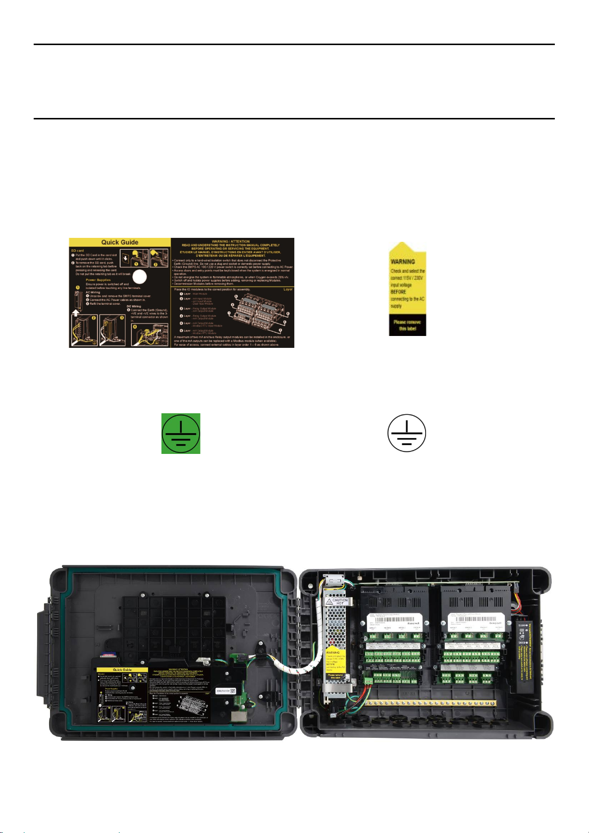
Figure 1. Quickstart Guide Label
(Not to Scale)
Figure 3. Protective Earth (Ground) Point Figure 4. Equipment Earth (Ground) Point
This Protective Earth (Ground) location point label is
used inside the system and is not normally visible to
the operator.
Figure 2. SMPS Voltage Warning Label
(Removed During Installation)
This Equipment Earth (Ground) location point label is
used inside the system and is not normally visible to
the operator.
Figure 5. Internal Label Positions
8
Page 15
MAN0984_Iss 2_06/15 Touchpoint Plus
Technical Handbook
Safety Hazards, Warnings And Cautions
2.3 Electrical Hazards
Gas detection systems contain electrical supplies that are potentially dangerous and hence precautions must
be taken to prevent the risk of electrocution.
2.3.1 General Precautions
• Read the relevant manual before beginning any operating or service procedures.
• Only personnel trained and certified by Honeywell are authorized to service, fit or remove internal parts.
• Only the minimum number of trained personnel, consistent with safety, should have access to the area
while work is being carried out. If necessary, erect warning signs and barriers.
• Follow accepted working procedures and codes of practice as well as the electrical safety code for the site
where the equipment is installed.
• Never operate the equipment under normal conditions with access panels removed or shorting links fitted.
• Do not “Live Test” without a Safe System of Work (SSoW).
• Always keep the area around the equipment dry and free of obstructions.
• Switch off and Isolate the equipment if water ingress is suspected or confirmed.
• Never operate the equipment if any Mains power cable is frayed or damaged.
• Never wear wristwatches, rings, bracelets, or other jeweler when working around electrical circuits or
moving parts.
• Take anti-static precautions when working on electronic circuits.
• Never work on electrical equipment alone.
2.3.2 Component Testing and Replacement
Before carrying out any electrical testing or component replacement:
• Read this Manual to become familiar with the location of high voltage components.
• Isolate the system at the main circuit breaker, lock it in the “Off” position, and attach a notice indicating
that maintenance work is in progress.
• Always wait for 5 minutes after isolating the equipment to ensure that stored energy has dissipated.
• Never assume the polarity of cabling or replacement components. Refer to electrical schematics or
contact Honeywell for confirmation.
• Use only Honeywell approved replacement parts.
Only Honeywell trained and certified maintenance technicians are authorised to carry out component testing and
replacement. Unauthorised work may result in a potentially dangerous situation and will invalidate the
Antistatic Precautions are required to prevent severe damage to electronic components.
Warning – Unauthorised Personnel
manufacturer’s warranty.
Anti–Static Precautions
9
Page 16
MAN0984_Iss 2_06/15 Touchpoint Plus
Technical Handbook
Safety Hazards, Warnings And Cautions
2.3.3 Antistatic Precautions
As with all modern electronic circuits, the Printed Circuit Boards (PCBs) in Touchpoint Plus systems utilize
some static-sensitive components that can be severely damaged if subjected to static discharge. Static can be
generated on the human body by friction or movement and is discharged through the first contacted route to
earth. It can also jump gaps between items of differing electrical potential.
Static damage is not always immediately apparent and can cause component failure at any time after the
static discharge has occurred. It is, therefore, very important that everyone takes the following precautions
when handling PCBs:
• An industry approved antistatic wrist strap, containing a resistive component greater than 1Megohm, must
be worn and connected to an effective earth (ground) point. The continuity between the strap and earth
(ground) must be checked regularly.
• PCBs must only be handled by their non-conductive edges. Do not allow any components, conductive
tracks or contacts to come into proximity with the body, clothing, machinery, power source or any material
other than a static-dissipative mat.
• With the exception of assemblies containing batteries, anti-static packaging must be used for transporting
PCBs and Integrated Circuits (ICs). All Touchpoint Plus electronic components are shipped in appropriate
packaging that can be re-used when returning items for test or repair.
• Avoid wearing clothing manufactured from, or containing a high proportion of, man-made fibers. These
can build up a high static potential that may not be discharged through the body or wrist strap.
An effective earth (ground) point is the protective earth (ground) bus bar inside the enclosure. This can be
used to connect a suitable anti-static wrist strap provided that the Gas detection system is connected to
protective earth (ground) via the mains power supply cable.
If installed correctly, the equipment earth (ground) point is connected directly to mains earth (ground) via
protective earth and the mains power supply cable. It is not dependent on the position of the Isolator switch or
Important
circuit breaker.
2.3.4 Good Practice
After switching off the system, it is good practice to wait at least 15 seconds before switching it on again. This
allows the circuits and RAM to discharge adequately before being powered-up again. Failing to do so may
cause data corruption.
2.3.5 Lithium Battery Hazard
Lithium batteries are fitted to Touchpoint Plus as backup power sources.
Replace the factory installed battery pack TPPLOIBB with Honeywell Analytics Asia Pacific replacement
battery pack part no. TPPLSIBB and the PCB CMOS battery with type CR2032 only.
Use of other batteries may present a risk of fire or explosion.
10
Lithium batteries may cause severe injury or death if ingested, and may catch fire or explode if mishandled,
Always handle lithium batteries with care, keep them out of the reach of children, and dispose of them carefully in
Lithium Battery Toxic and Fire Hazards
recharged, burned or disposed of incorrectly.
accordance with local regulations.
Page 17
MAN0984_Iss 2_06/15 Touchpoint Plus
Technical Handbook
Safety Hazards, Warnings And Cautions
2.4 Product Compliance
This product complies with the following standards and directives.
Other safety directives may apply to the complete system installation if an OEM’s product is integrated into
other equipment or machinery.
Safety Compliance
Electrical Safety
EMC/RFI
Low Voltage Directive
Gas Performance*
CAN/CSA C22.2 No. 61010-1 and No.142
UL 61010–1 (3
IEC/EN 61010–1 (3
EN 50270
IEC/EN 61010–1 (3rd Edition)
ISA 12.13.01 and CSA C22.2 No. 152
rd
Edition); UL508
rd
Edition)
* ISA 12.13.01 and CSA C22.2 No.152 approval is applicable only to mV sensors Model 705 and MPD or any
suitably certified mA sensor.
Note: The Equipment referred to in this manual contains components and assemblies that are each certified
for use in a variety of differing environments, and it is the site owner’s responsibility to confirm the suitability of
the equipment prior to its installation and use.
Please check the product rating plate and look for the following marks to ensure that the supplied
equipment is suitable for its intended location and purpose:
Products bearing the CE mark conform to all applicable European Directives as stated on the Honeywell
product specific EC Declaration of Conformity.
Products bearing the UL mark conform to the requirements for Ordinary Locations. The letters C and US
mean that the product is certified for use in Canada and the United States of America.
Read and understand the instruction manual before operating or servicing the equipment.
Important
11
Page 18

MAN0984_Iss 2_06/15 Touchpoint Plus
Technical Handbook
Safety Hazards, Warnings And Cautions
2.5 Conditions of Use
This Touchpoint Plus equipment should only be operated under the following circumstances:
• By properly trained personnel.
• Under approved conditions.
• With due authorization.
• Using approved maintenance and servicing procedures.
2.5.1 Training of Personnel
Honeywell and / or its distributors can provide training for operators and maintenance personnel. Personnel
who have been trained in operation and maintenance shall be limited to carrying out only those procedures
and tasks taught during the training course. Honeywell certified maintenance technicians must carry out all
other tasks.
Honeywell can also provide additional or advanced training. Retraining is recommended periodically and
whenever equipment is upgraded.
2.5.2 Conditions Satisfying Local, National and International Safety Regulations
Approved conditions must satisfy the requirements of applicable national and international safety standards
and statutory requirements relating to electrical, EMC, and health hazards. In addition, they must satisfy the
requirements of the Site Safety Officer and the local safety regulations.
2.5.3 Due Authorization
Before any production, maintenance, or servicing procedure is carried out; written authorization must be
obtained from one of the following personnel to confirm that the proposed task satisfies the necessary safety
conditions:
• A competent authorized person having a professional qualification in an appropriate technical discipline.
• The Factory, Technical or Engineering Manager responsible for the working area.
• The Site Safety Officer or an authorized Honeywell representative or approved distributor.
2.5.4 Approved Maintenance and Servicing Procedures
Approved Maintenance and Servicing Procedures are those stipulated in this manual or as authorized
separately by Honeywell.
It may be necessary to establish a temporary Locally Controlled Area (LCA) to restrict access during
maintenance, testing or service of this equipment.
12
Page 19
MAN0984_Iss 2_06/15 Touchpoint Plus
SD Card
Audio / Visual Alarm
mA Loop Sensors
Relays / Actuators
mA Loop
mV Bridge Sensors
Technical Handbook
System General Descri ption
Chapter 3 – System General Description
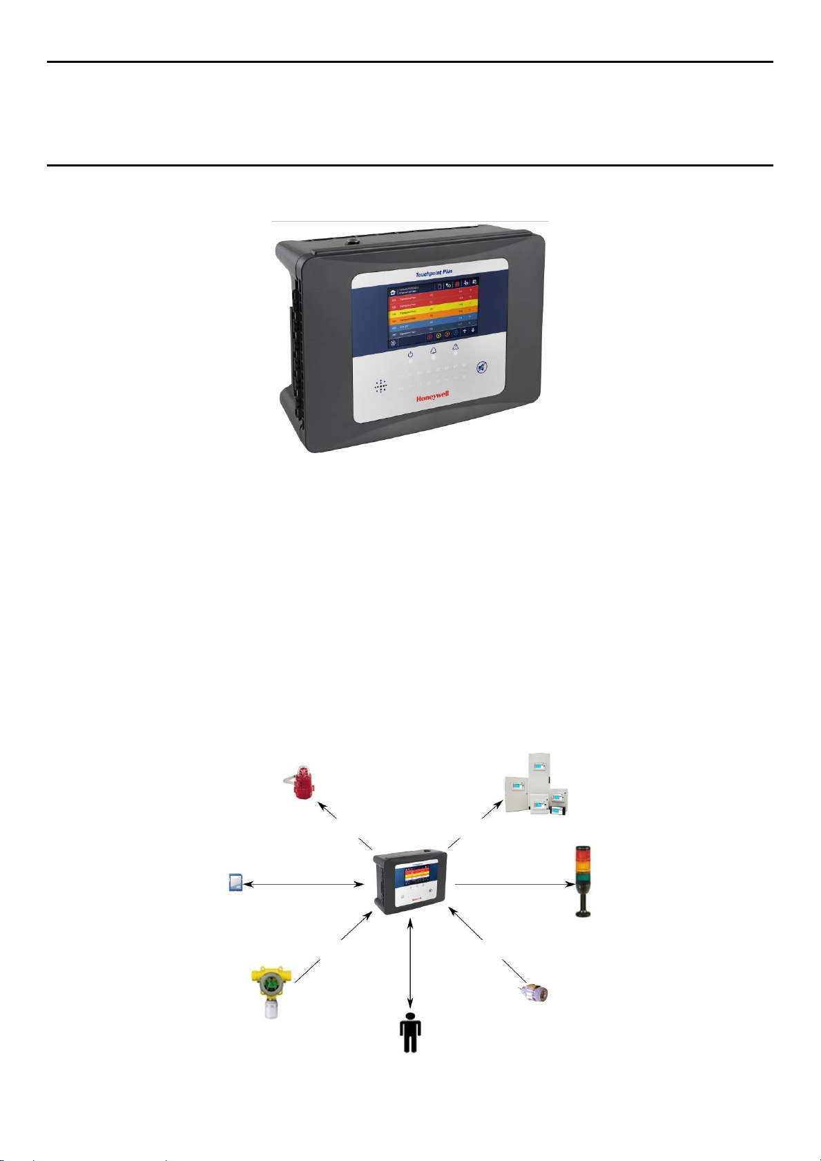
Figure 6. Touchpoint Plus Wall-Mounted Controller
The Touchpoint Plus is an entry level (or upgrade) touch-screen digital Controller for general industrial and
commercial gas detection systems. It has eight input channels, with a further eight channels available through
an optional expansion unit*.
It can handle a wide range of milliamp, millivolt, and catalytic sensors through analogue inputs, and it can
control various outputs such as audible and visible signals and solenoid valves.
The cabinets are constructed from high-impact plastic and have fully-sealed, easy opening access. They are
supplied with a wall mounting or can be directly mounted to any solid vertical surface or rack. Cable entry is
via entry glands on the lower side.
Touchpoint Plus is rated IP65, which means that it is dustproof and can be subjected to low-pressure water
without significant ingress. This makes it particularly suited to offices, control rooms and unheated boiler
rooms.
*Currently Touchpoint Plus is only available as a stand-alone Gas Detection System, but please contact
Honeywell Analytics for details about future upgrades. (The expansion box is currently planned for release in
late 2015.)
Figure 7. Typical Installation Options
13
Page 20
MAN0984_Iss 2_06/15 Touchpoint Plus
Technical Handbook
System General Descri ption
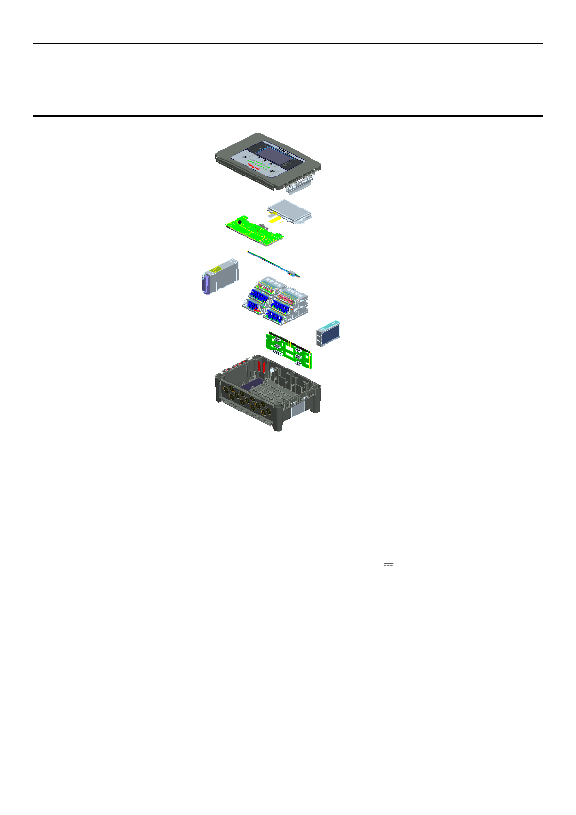
Figure 8. TPPL Controller Exploded View
Both the Touchpoint Plus and its optional expansion unit have the option for AC, DC and battery backup
power supplies.
Note: The expansion unit will be available from late 2015.
Other features:
• Color LCD Touch Screen with multi-language GUI and menus
• Password protection
• Flexible Mains Power Input: 50 – 60 Hz 110/220 V ~ (AC), 18 – 32 V (DC), Max 105 W
• Up to 8 channels of Analogue Input (0–22 mA, Bridge mV for Cat bead)
• 2 or 3-wire signal inputs
• Up to 24 channels of user configurable relay controlled Output
• Up to 8 channels of configurable mA Output
• Alarm update on Acknowledge
• Automatic Self-Diagnostic with error codes
• Event recording
• SD Card
14
Page 21
MAN0984_Iss 2_06/15 Touchpoint Plus
Technical Handbook
System General Descri ption
3.1 Equipment Specification
3.1.1 Power Requirements
The Touchpoint Plus system is designed to operate on a single phase, 50 to 60 Hz, 110/220 V~ (AC) supply
with a typical power consumption of less than 105 W.
Alternatively it can be connected to an 18–32 V (DC) supply with typical power consumption less than
105W.
The system can contain an optional backup battery to guard against short-term power disruption.
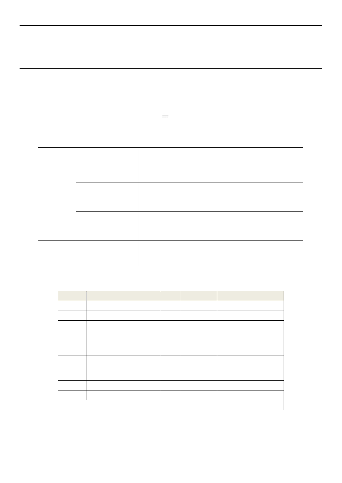
Input
Output
Protection
Voltage Range AC
AC Frequency Range 50 – 60 Hz ± 6%
AC Current Draw (typ.) 3 A @ 115 VAC, 2A @ 230 VAC
Cold-start Current (typ.) 40 A @ 230 VAC
Leakage Current <2 mA @ 240 VAC
DC Voltage 24 V
Rated Current 6.5 A
Current Range 0 – 6.5 A
Rated Power 156 W
Overload 110 – 150 % rated output power
Over-Volt
Table 1. Power Supply (SMPS RS–150–24) Electrical Ratings
No Modules Qty Power (W) Remarks
1 UI Module 1 3.6 Max
2 Main Module 1 1.7 Max
3 mA Input Module 1 0.9
4 mA input Field Device Power 8 40.0 Max
5 mA Output Module 2 8.6 Max
6 Relay Output Module 2 2.0 Max
7
Charging power for backup
battery pack
AC 110/220 V manually switchable
300 VAC surge for 5 sec without damage
27.6 – 32.4 VDC Hiccup mode, which recovers automatically when
the fault is removed.
Max (not including
detector power)
1 5.3 Max
8 Audio/Visual Alarm 4 28.8 Max
9 SMPS Power Loss — 14.0 Max
MAX TOTAL 104.9
Table 2. System Power Calculations
—
15
Page 22
MAN0984_Iss 2_06/15 Touchpoint Plus
Technical Handbook
System General Descri ption
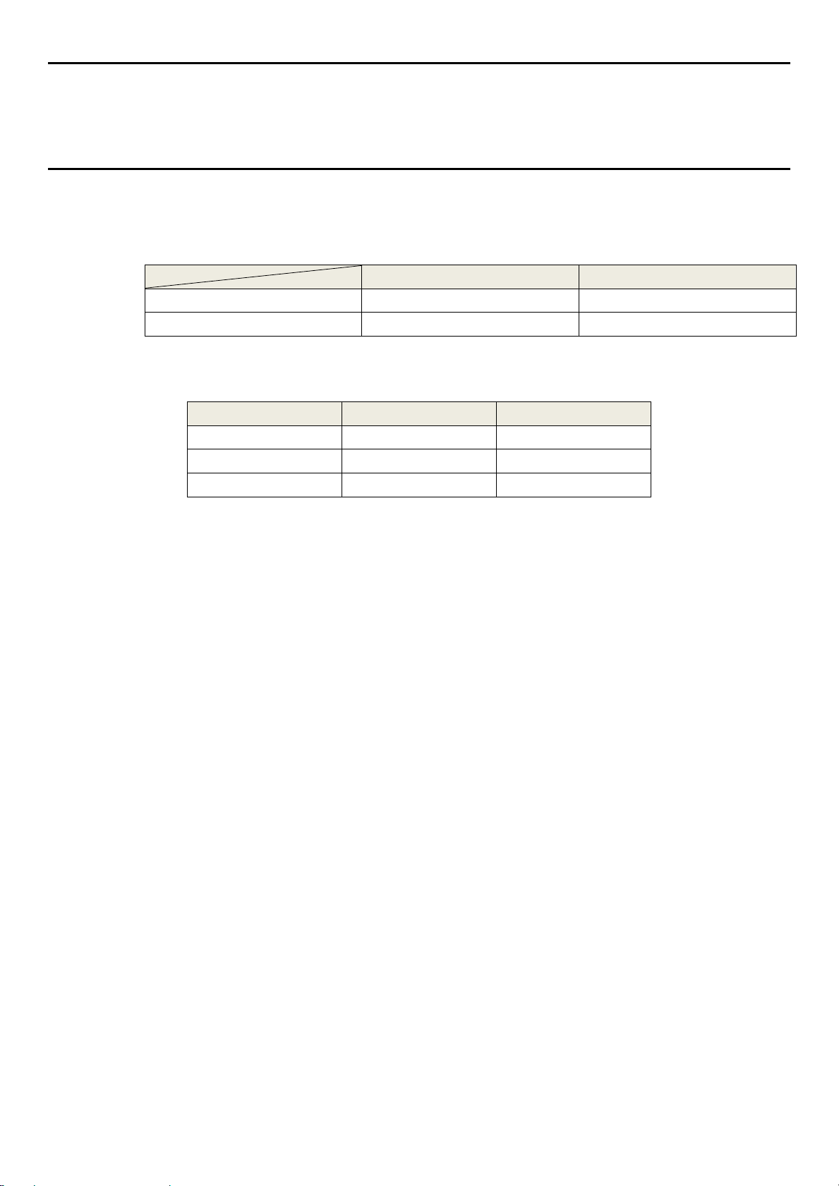
3.1.2 Weights
Note: Based on one input module, two mA output modules, two output relays, SMPS and backup battery for
the basic unit and expansion unit respectively.
TPPL Basic Unit TPPL Expansion Unit
System alone
System with packaging
Table 3. System Weights
3.1.3 Dimensions
External Dimension Millimeters Inches
Depth
Length
Width
8.5 Kg (18.7 lbs) 8 Kg (17.6 lbs)
9 Kg (20 lbs) 8.5 Kg (18.7 lbs)
156 6.2
426 16.9
300 11.8
Table 4. System Dimensions
3.1.4 Ambient Operating Temperature
–10 °C to +55 °C (14 °F to 131 °F)
3.1.5 Overall Ambient Operating Humidity
5 % to 95 %RH, non-condensing
3.1.6 Storage Conditions (Without batteries)
–25 °C to +60 °C (-13 °F to 140 °F), @ 5 % to 95 %RH, non-condensing
3.1.7 Storage Conditions (With batteries)
1 year: –20 °C to +25 °C (–4 °F to +077 °F)
3 months: –20 °C to +45 °C (–4 °F to +113 °F)
1 month: –20 °C to +60 °C (–4 °F to +140 °F)
3.1.8 IP Rating
The enclosures are sealed to IP65 when appropriate cable entry glands are used.
3.1.9 Construction
The system cabinets are constructed from PC ABS plastic with a secured quick release front access door
panel.
The Controller door panel holds a touch sensitive color LCD with a membrane cover over additional buttons,
LEDs and an audible warning horn.
Inside the Controller cabinet is a Switched-Mode Power Supply (SMPS) providing a nominal DC 24 V output,
an optional Lithium-ion backup battery, a Main Module, a mA/mV Input Module, two mA Output Modules, two
Relay Modules, protection fuses, and the control and user interface electronics.
The optional expansion unit holds the same modules and optional backup battery, but has no controller or
user interface.
Both enclosures contain a common Earth (ground) rail that must be bonded to Protective Earth (Ground)
through an isolation switch that does not disconnect the Earth line.
16
Page 23
MAN0984_Iss 2_06/15 Touchpoint Plus
1 2 3 4 4 5 5 7 6
8
12
10
9
11
Technical Handbook
System General Descri ption
3.1.10 Touchpoint Plus Packaging
• Touchpoint Plus outer packaging is made from cardboard. Facilities for recycling are widely available.
• Touchpoint Plus inner packaging is made from Stratocell®, Low-Density Polyethylene (LDPE) foam. The
foam can be recycled into new Stratocell® where such recycling facilities exist.
3.1.11 Packaging Components for Return to Manufacturer
Honeywell is unable to accept any consignment that does not conform to the European Classification,
Labeling and Packaging (CLP) Regulations (EC) 1272/2008.
Please consult your distributor, supplier, or the manufacturer if you require further advice.
3.1.12 Disposal (WEEE Directive)
The system contains Lithium batteries and a number of homogenous hazardous materials. These should be
disposed of carefully in accordance with the WEEE Directive and local laws and guidelines. Under no
circumstances can they be disposed of as domestic waste.
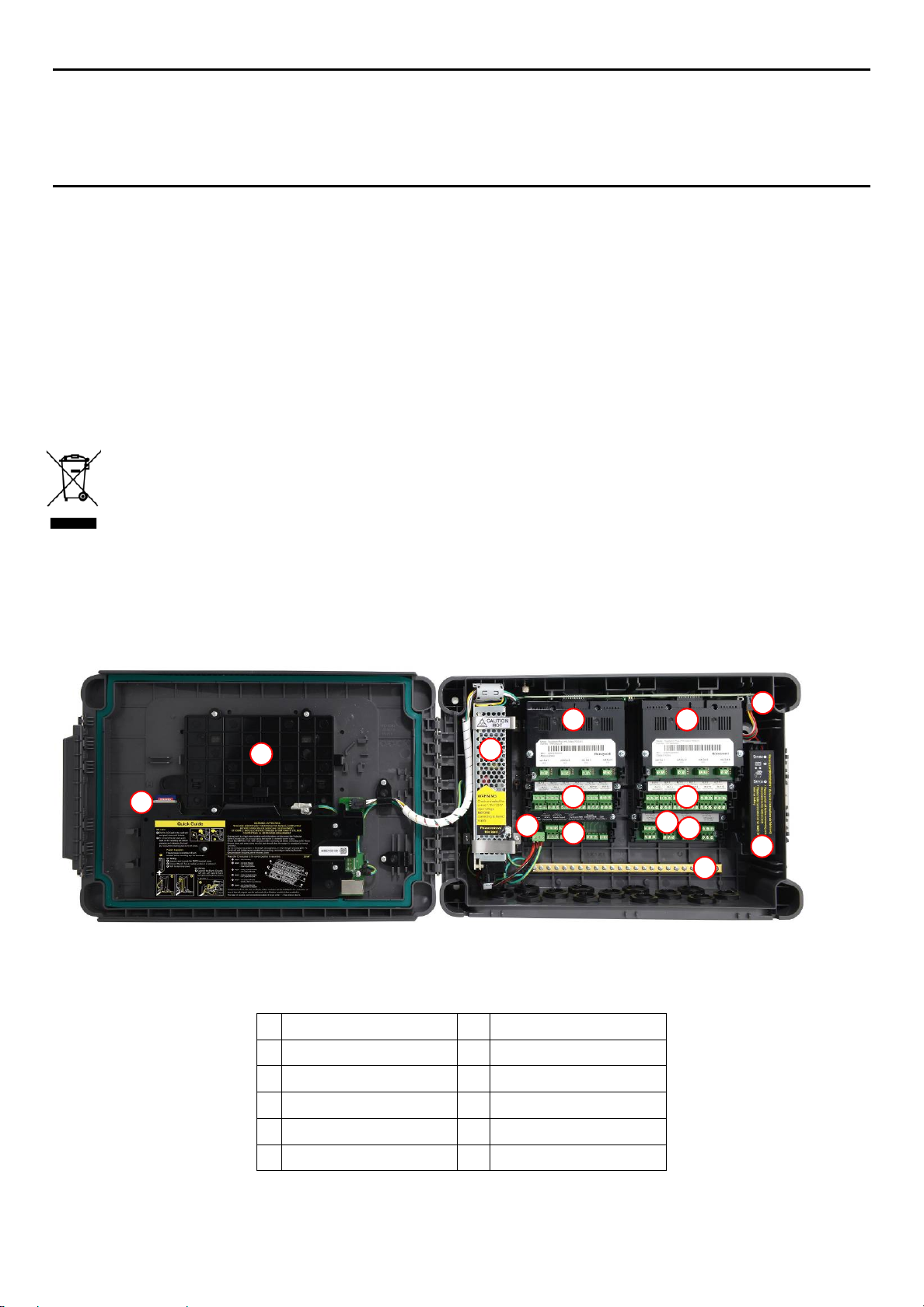
3.2 System Construction
This figure shows the basic building blocks of the Touchpoint Plus system. The optional Expansion Unit will
not have any of the items seen on the left hand (door) panel.
1
2
3
4
5
6
Figure 9. System Layout Before Installation
Touchscreen
SD Card
SMPS
mA Output Modules
Relay Output Modules
Power Terminal
7
Main Module
8
mA Input Modules
9
mV Input Modules
10
Earth (Ground) Bus Bar
11
Battery On / Off Switch
12
Backup Battery
17
Page 24
MAN0984_Iss 2_06/15 Touchpoint Plus
Technical Handbook
System Mechanical I nst all at ion
Chapter 4 – System Mechanical Installation
The system can be directly wall-mounted or on an optional mounting fixture. Whichever method is chosen, the
mounting must be sound, secure, and capable of supporting the weight of the enclosure plus the weight of
any cables and glands.
When choosing a location, it must be easily visible and accessible, with room to mount an external power
isolator. There must also be room to fully open the access door, which opens to the left, and room to easily
access the door locking handle and its securing screws, which are situated on the right. If using the expansion
unit (available late 2015), there must be room to mount both boxes side-by-side with space between them to
access the locking handle and its securing screws.
The units should be mounted so that the screen can be easily accessed and seen, but they should not
obstruct accesses, walkways or exits.
Although the units are IP65 when installed correctly, they should be mounted away from heat sources, out of
direct sunshine, and should be protected from rain, severe weather, steam or excess humidity and
condensation.
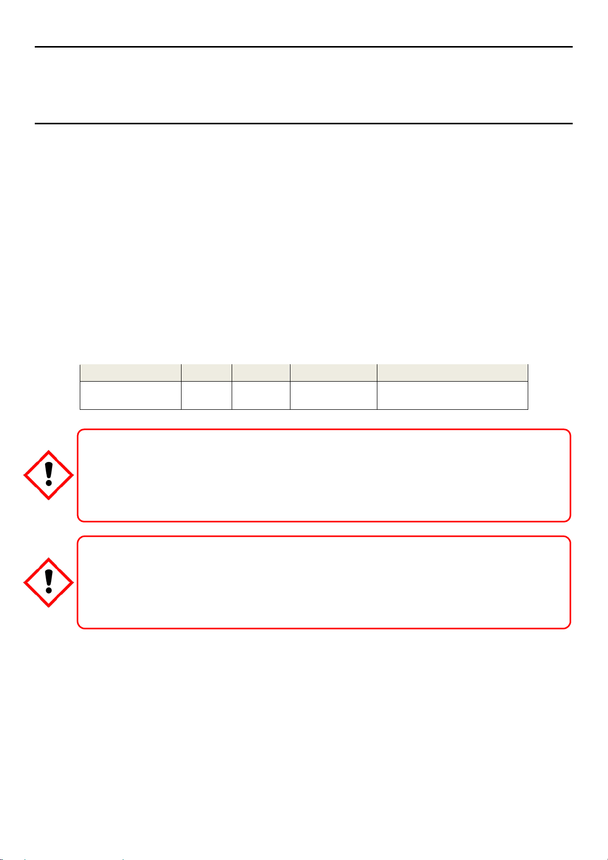
These units have only passive cooling, so an adequate airflow must be maintained to prevent overheating.
Assembly IP NEMA Pollution Degree Remarks
Wall mounted cabinet 65 4X 2
It is the Customer’s responsibility to ensure that the equipment is correctly installed, and that cable entry glands
Failure to do so will invalidate the quoted IP / NEMA / Pollution ratings and may invalidate the warranty.
The units as supplied have two hex-socket securing screws in the access door handle, and these have to be
undone prior to opening the handle. Failing to do so could cause irreparable damage to the housing.
The handle must be correctly locked and the screws must be correctly tightened when the unit is in operation.
Failing to fully secure the enclosure is unsafe and will invalidate product certification.
or blanks of the appropriate IP rating are correctly used.
Caution
Caution
When properly installed using the
appropriate cable entry glands
18
Page 25
MAN0984_Iss 2_06/15 Touchpoint Plus
1 2 3
Technical Handbook
System Mechanical I nstallation
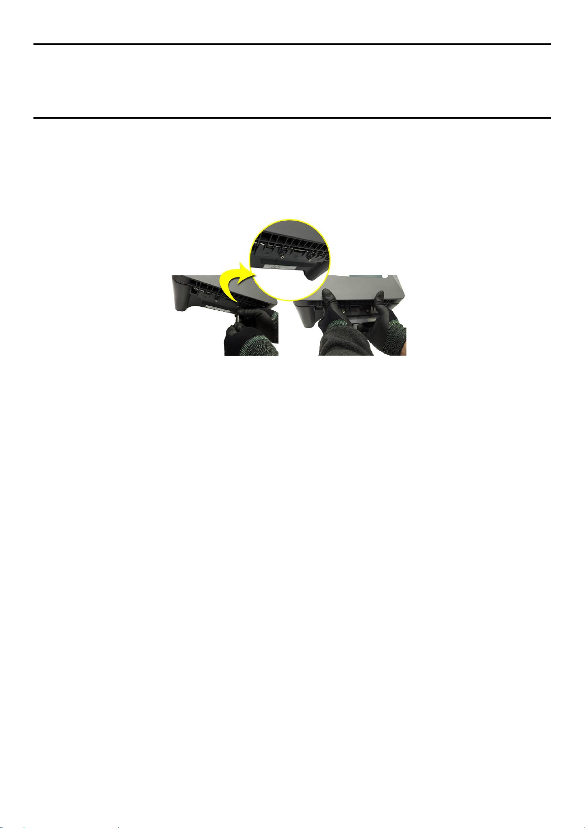
4.1 How to Open and Close the Enclosure
1) Ensure that it is safe to open the enclosure and, if necessary switch off and isolate electrical power.
2) Unscrew the two 3mm Hex socket security screws (1) until they become loose (2).
3) With a gloved hand only, pull the handle until it comes free (3). Do not apply undue force.
4) Open the enclosure door fully.
Figure 10. Undoing the Security Screws and Opening the Enclosure
5) Closure is the reverse of this procedure, but care must be taken not to exert undue force, and you must
not press on the membrane or touch screen areas.
Note: The door recess has an environmental seal that requires some pressure to close the door correctly.
The enclosure handle is the primary method of applying this pressure but you can assist it by pressing on the
door edge directly above the handle as you press on the handle itself.
19
Page 26
MAN0984_Iss 2_06/15 Touchpoint Plus
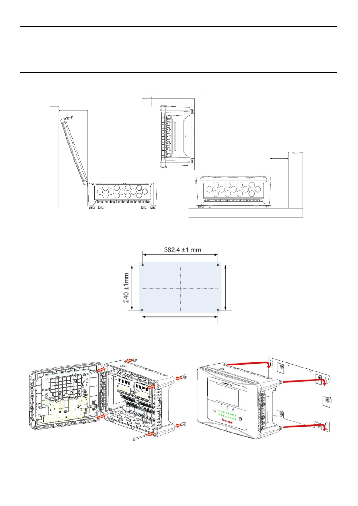
Minimum Wall
Clearance 175.5 mm
Minimum Wall Clearance 100 mm
Technical Handbook
System Mechanical I nstallation
4.2 Wall Mounting Requirements
Minimum Ceiling Clearance 20 mm
Figure 11. Installation Clearance Measurements
Figure 12. Wall Mounting Template
Figure 13. Wall and Plate Mounting Points
You can use the wall mounting plate as its own template and location guide, and you should ensure that the
mounting bolts are adjusted to fit the plate bayonet holes before fixing the plate to the wall.
20
Page 27

MAN0984_Iss 2_06/15 Touchpoint Plus
Enclosure Corner
Plate
Technical Handbook
System Mechanical I nstallation
4.2.1 Wall Mount Fixings
You will require the following locally sourced items to install the Touchpoint Plus:
Tool to undo the enclosure access handle security screws:
• 3 mm Hex key
Suggested Fixings to screw the enclosure to the wall only:
• Screw Max. Dia: 6.4 mm (#14) dome or cheese head screw
• Screw Min. Length: 76 mm (3 in.) – Normal fix
• Washer Max. Dia: 14.3 mm (0.56 in.)
Note: The sizes above are given to allow for clearance in the TPPL Enclosure. The actual length and type of
fixing should be determined by the surface material and the type of anchor required.
Suggested Fixings for using the Mounting Plate:
For the plate, choose fixings appropriate to the surface and the weight of the enclosure plus cables. You will
also need to use suitable bolts, washers and lock nuts (see diagram below).
Ideally you will mount the enclosure and cables on a ≥20 mm ply board to allow cable troughs to be used.
Figure 14. Fixing Orientation When Using the Optional Mounting Plate
Wall or
Board
Note:
You should ensure that washers between the TPPL enclosure and the wall or mounting plate are sufficiently
large to spread the load evenly.
• For metal conduit, use a metal ground plate (i.e. Part No: TPPLOMGND).
• For external visual/audio outlet, ensure IP65 is maintained (i.e. Part No: M-700123).
• For cable gland, use type PG16 and tighten to 44.2 lb-in torque.
21
Page 28
MAN0984_Iss 2_06/15 Touchpoint Plus
Technical Handbook
Electrical Pow er And Inter f acing
Chapter 5 – Electrical Power Connection and Interfacing
All power supplies must be hard wired and must include a circuit breaker (RCD / RCCB), and (close by and
unobstructed) a means of manually isolating and locking out the power supply without breaking the protective
Removable plug and socket connection is not permitted under any circumstance.
Lethal current may be present in this equipment when electrical power is applied. There is a danger of death or
injury from electrical shock. Isolate power before opening electrical access panels. Ensure residual current is fully
Lethal current may be generated both internally and externally to the system. All installations, including remote
units and cables, must be connected to protective earth, and must be capable of remaining so when the power
Honeywell can accept no responsibility for any damage or injury caused by incorrect or faulty wiring.
It is the custo me r ’s r esponsibility to provide appropriate power supplies to the TPPL and detectors.
Warning – Electrical Shock Hazard
earth (ground) connection.
Warning – Electrical Shock Hazard
discharged before touching live terminals.
Warning – Electrical Shock Hazard
supply is interrupted.
Protective earth is shown by the green sym bol on the left.
Warning
5.1 Power Connection
The TPPL systems are factory set to operate at a manually switchable voltage of AC 110/220 V on single
phase, 50 to 60 Hz supplies. They can also be connected to DC 18 – 32 V SELV without backup battery or
DC 24 – 32 V SELV if using the backup battery option.
All systems have a typical peak power consumption of less than 105 W, and must be directly connected to
supplies via a Main Isolator Switch that leaves protective earth (ground) permanently connected. The circuit
should incorporate a Residual Current Device or Residual Current Circuit Breaker (RCD or RCCB).
TPPL systems are not certified for connection to domestic power supplies.
The system is normally supplied with the voltage pre-set to the customer’s specifica ti o n . If the supplied voltage is
22
incorrect, it must be altered prior to connecting to the mains power supply.
Warning
Page 29
MAN0984_Iss 2_06/15 Touchpoint Plus
AC Line
AC Common
F – Ground (Not Us ed)
AC Input
DC Output
-Ve DC
-Ve DC
+24 VDC
+24 VDC
+24 V DC In
Ve DC Return
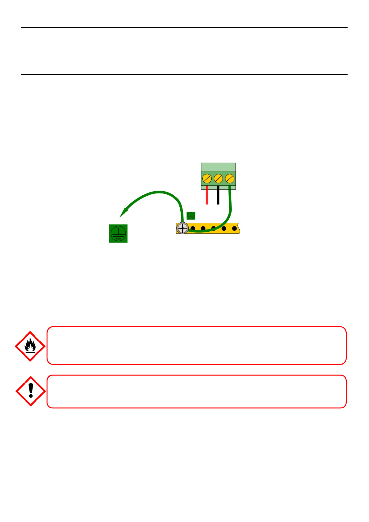
Earth (Ground)
Protective
System Ground Bus Bar
Technical Handbook
Electrical Pow er And Inter f acing
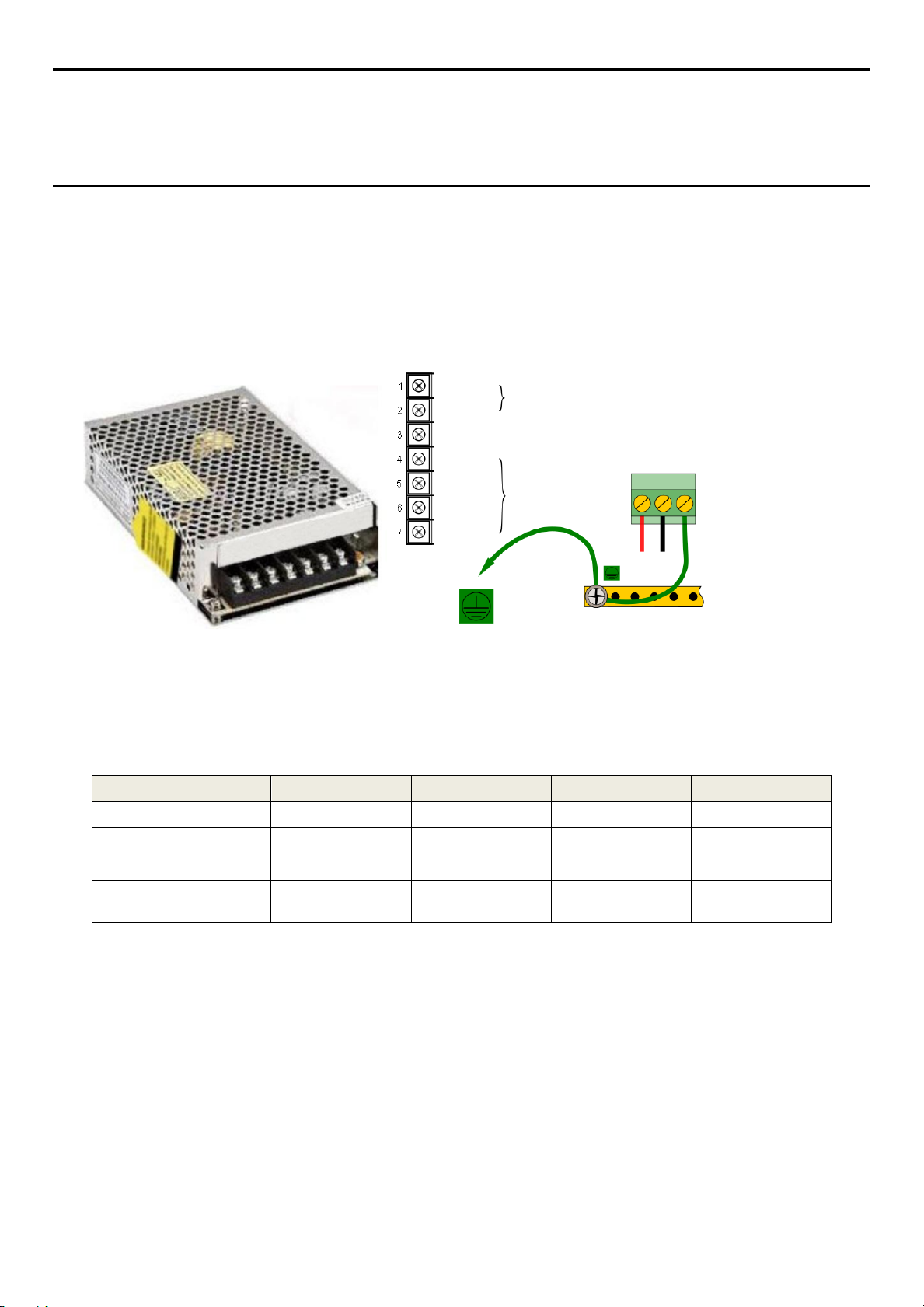
5.1.1 AC Power Supply
To confirm or alter the pre-set operating voltage, open the system front cover, locate the SMPS transformer
on the left side and, if required, change the voltage selector using a screwdriver at the point shown by the
yellow and black label below:
Figure 15. Switched Mode Power Supply (SMPS) Connections
Earth
(Ground)
-
Note: Mains Earth (Ground) must only be connected to the protective earth (ground) rail, and not to the
SMPS.
Regional power cable wires are colored in accordance with the following code:
Wire Europe USA CAN India/Pakistan
Protective Earth (Ground) Green + Yellow Green Green Green
Isolated Earth (Ground) — Green + Yellow Green —
Neutral Blue White White Black
Line Brown Blue, Red, or Black Red or Black
Red, Yellow, or
Blue
Table 5. Regional Power Cable Colors
Before making any electrical connections or changes ensure that:
• the mains supply isolator switch is in the Off position
• the system is set up to operate at the correct voltage
Refer to Ch. 3.1.1 Power Requirements for further information on system electrical specifications.
Note 1: Input voltage of less than DC 23.5 V will fail to charge the backup battery, and it will generate a
“battery unchargeable” warning message.
Note 2: Field detectors may need their own power supplies if they exceed 15 W per channel or a combined
total of 40 W. Refer to Table 7: mA Input Module Connections for further information.
23
Page 30
MAN0984_Iss 2_06/15 Touchpoint Plus
will be reduced if the charging supply is <24 V.
+24 V DC In
-Ve DC Retur n
Earth (Gr ound)
Technical Handbook
Electrical Pow er And Inter f acing
5.1.2 DC Power Supply
It is possible to power the Touchpoint Plus controller directly from a DC 18 – 32 V supply without using AC
supplies at all. However, batteries alone may quickly drop below the minimum DC 18 V requirement when
under load.
Note: The system must still be connected to protective earth (ground) when using an external DC supply.
Protective
Earth
(Ground)
System Ground Bus Bar
Figure 16. Connections for DC 24 V Supply
5.1.3 Backup Battery Pack
The Touchpoint Plus can have an optional rechargeable 24 volt Lithium-Ion Battery Pack. This would normally
be charged by the SMPS, but can be charged by a separate DC 23.5 – 32 V supply.
Note: The backup battery requires minimum 24 V input to fully charge, and it has a non-replaceable 15 A
over-current protection fuse so do not exceed 32 V, 5 A charging input.
DO NOT USE WATER as this can cause them to burn violently or they may explode.
The battery should be charged at DC 24 – 32 V. The backup battery will not be fully charged and the backup time
Danger
In the event of Lithium batteries overheating:
Important
24
Page 31

MAN0984_Iss 2_06/15 Touchpoint Plus
Technical Handbook
Electrical Pow er And Inter f acing
5.2 Cabling Requirements
All cabling shall be appropriately rated and approved in accordance with national and local regulations.
Additionally, cabling must satisfy the requirements defined in the manuals of connected field devices, particularly
if the field device is certified for use in a hazardous location.
Signal cables should be shielded to avoid spurious signals, and shall be bonded to prot ective earth (Ground).
5.2.1 AC Mains Voltage Power Cables
Care must be taken to avoid Ground feedback loops.
Warning
Use a properly rated AC power (mains) cable, certified and installed in accordance with local and national
regulations. The Touchpoint Plus terminals will accept only copper wire sizes in the range 0.4 – 4 mm2 (solid
core), 0.4 – 3 mm2 (stranded core), or 21 – 12 AWG (T
1.35 Nm (11.9 lb-in).
5.2.2 DC Power Cables
Use a properly rated DC power (mains) cable, certified and installed in accordance with local and national
regulations. The Touchpoint Plus terminals will accept only sizes 0.9 – 3.3 mm2 (solid or stranded copper
cores), or 18 – 12 AWG (T
5.2.3 Field Device Cables
Field Device cabling (sensors, lights, solenoids, etc.) should be appropriate to the zone classification, and in
accordance with the device manufacturer’s recommendations. Refer to local and national regulations where
appropriate, and to the device user manual.
All sensor field cables must be screened and earthed (grounded) in order to:
• ensure correct operation of the system
• avoid spurious signals
• provide lightning protection
• Meet European Standards for RFI and EMC
The I/O modules will accept only copper wire sizes to a maximum of 2 mm² or 14 – 30 AWG, with the
terminals torqued to 0.5 Nm (4.4 lb-in).
Ensure that the maximum loop resistance is not exceeded, as specified by the device manufacturer.
Ensure that the correct power level is present at the field device, as specified by the device manufacturer, and
does not exceed the TPPL supply limit of 15W per channel individually or 40 / 68 W in total. (See the notes
under 5.2.5 Main Module Connections for more details about power consumption and availability.)
I.e. if a device’s supply requirement is 24 VDC 0.5 A, then the power requirement is 24 V x 0.5 A (V x I) = 12
W. If you use 240m of AWG 22 cable (R = 0.05 Ω/m), the power line dissipation is 0.05 Ω/m x 240m x 0.52 A
(R x I2) = 3 W. Therefore the total power requirement is 15 W (12 + 3).
You should also test the cable resistance in situ as its actual resistance is relative to T
any added end of line (EOL) resistance).
>80 °C). The mains terminals should be torqued to
amb
>80 °C). The mains terminals should be torqued to 0.5 Nm (4.4 lb-in).
amb
(taking into account
amb
25
Page 32
MAN0984_Iss 2_06/15 Touchpoint Plus
AC Line
AC Common
+24 V DC
DC Return
Earth (Gr ound)
+24 V DC
DC Return
Earth (Gr ound)
AC Line
AC Common
Ground
Ve DC
Ve DC
+24 VDC
+24 VDC
Touchpoint Plus Controller
Optional Expansion Unit
Technical Handbook
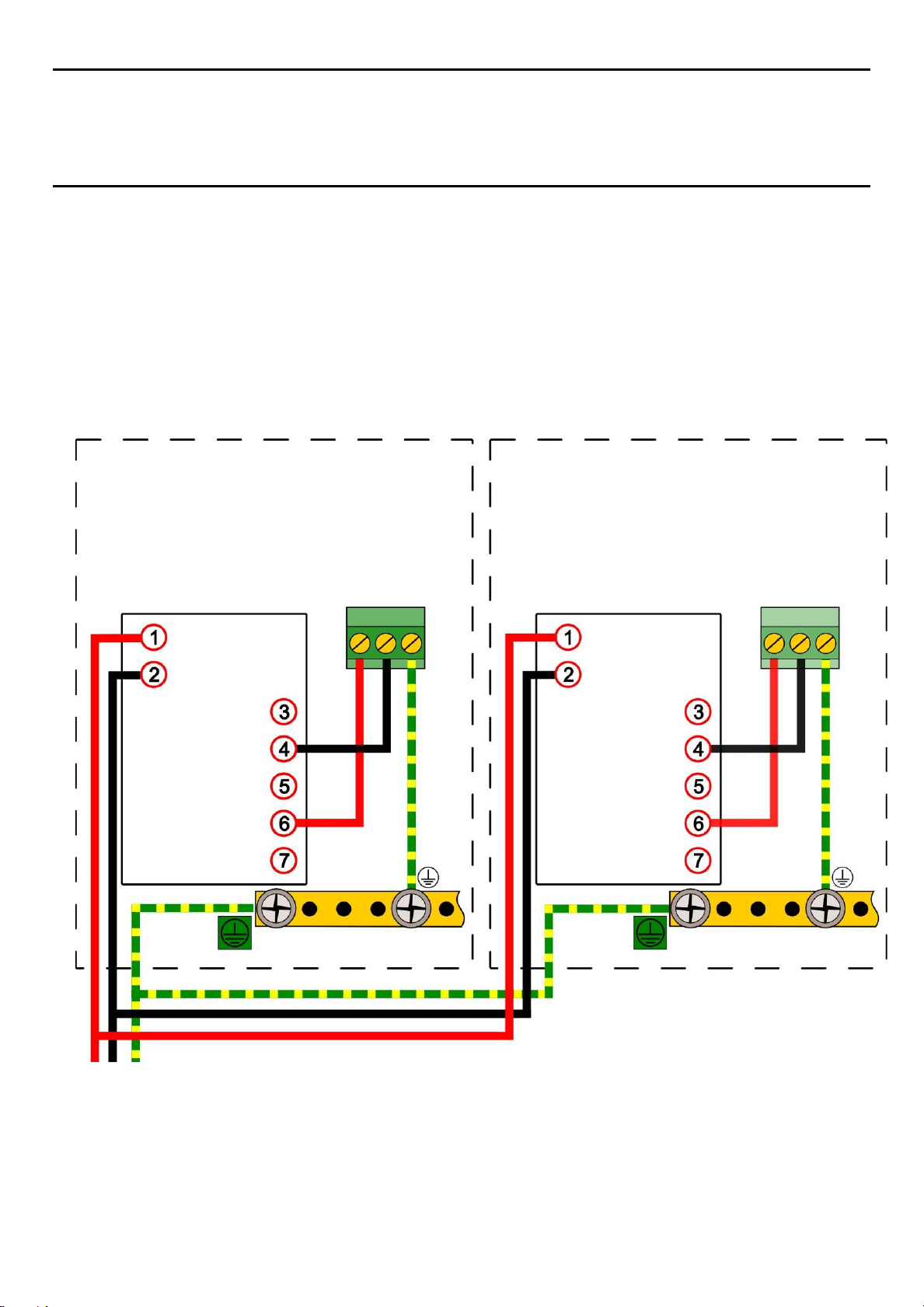
5.2.4 Optional Expansion Unit Connection (available late 2015)
Electrical Pow er And Inter f acing
In general, the expansion unit should have the same cabling and similar power requirements as the
Controller:
• 2-core cable plus Earth
• Shielded signal cables
• <10 meters from the controller
• avoid Earth (Ground) loops
The SMPS can deliver 150 W maximum, however a basic unit and an expansion unit each need 105 W so
must be wired as shown below when using AC Mains input.
F-Ground
-Ve DC
-Ve DC
+24 VDC
+24 VDC
Ground Bus Bar
Note: The SMPS is attached to chassis ground and does not need a separate ground connection.
Figure 17. Connecting the Touchpoint Plus and Optional Expansion Unit to a Mains Supply
–
F-
-
-
Ground Bus Bar
–
26
Page 33

MAN0984_Iss 2_06/15 Touchpoint Plus
Technical Handbook
Electrical Pow er And Inter f acing
5.2.5 Main Module Connections
Input / Output Field device Label Terminal
24 VDC +DC 1
Power
Channel Relay 001
(Alarm, Fault, Warning Or Inhibit)
Channel Relay 002
(Alarm, Fault, Warning Or Inhibit)
System Relay 003
(System Failure)
Dedicated Alarms
(Max 300 mA per channel)
External Alarm Power
GND –DC 2
Earth
— NC 4
— COM 5
— NO 6
— NC 7
— COM 8
— NO 9
— NC 10
— COM 11
— NO 12
Visible
Audible 1 A1 16
Audible 2 A2 17
Audible 3 F 18
— +24 VDC 19
— +24 VDC 20
— +24 VDC 21
Common 3.3 V 22
–
+24 VDC 13
VIS 14
Unused 15
3
Remote Inputs (Note 4)
Expansion Unit Connection
Table 6. Main Module Connections
Reset R1 23
Inhibit R2 24
CAN_High CAN_H 25
CAN_Low CAN_L 26
Note 1: +24 VDC Nominal = Controller Input (18 to 32 VDC) – 1.8 VDC (the max voltage drop in the TPPL).
Note 2: Alarm Terminals 13, 19, 20, and 21 can supply +24 VDC at ≤ 28 W combined but this 28 W can
instead be used to increase the power available to field sensors if external audible and visible alarms are not
connected.
I.e. the 8 sensor channels would normally have ≤40 W of combined available power, but this can be increased
to 68.8 W if terminals 13 – 21 are unused.
Note 3: You must supply sensors with external power if more than 40 / 68 W total power is required (See
Note 2).
Note 4: Maximum R
resistance for a remote reset/inhibit switch is 18 Ω, i.e. ≤500 m of 1 mm2 shielded
loop
cable.
27
Page 34

MAN0984_Iss 2_06/15 Touchpoint Plus
Touchpoint Plus
Main Module
Open
Drain
R Load
Touchpoint Plus
Main Module
Reset
(NO non-latched Sw.)
Inhibit
(NO latched Sw.)
Technical Handbook
Electrical Pow er And Inter f acing
Figure 18. Dedicated Alarm Circuit Connections
Figure 19. Optional Remote Reset and Inhibit Switch Connections
Maximum R
resistance for a remote reset/inhibit switch is 18 Ω, i.e. ≤500 m of 1 mm2 shielded cable.
loop
It is the user’s responsibility to ensure that Remote Reset / Inhibit switches are guarded against unauthorised
Warning
access or tampering.
28
Page 35

MAN0984_Iss 2_06/15 Touchpoint Plus
Touchpoint Plus
mA Input Module
Sensor
Technical Handbook
Electrical Pow er And Inter f acing
5.2.6 mA Input Module Connections
Note: mA input channels are limited to 15 W per channel to a combined total of 40 W (68 W if Main Module
Terminals 13 to 21 are not used). Sensors requiring more than 15 W (i.e. IR-F9 (Max 28W) must have their
own power supplies.
mA Input Channel Field device Label Terminal
+24 VDC +DC 1
1
0 VDC –DC 2
4 – 20 mA signal Sig 3
+24 VDC +DC 4
2
3
4
5
6
7
8
0 VDC –DC 5
4 – 20 mA signal Sig 6
+24 VDC +DC 7
0 VDC –DC 8
4 – 20 mA signal Sig 9
+24 VDC +DC 10
0 VDC –DC 11
4 – 20 mA signal Sig 12
+24 VDC +DC 13
0 VDC –DC 14
4 – 20 mA signal Sig 15
+24 VDC +DC 16
0 VDC –DC 17
4 – 20 mA signal Sig 18
+24 VDC +DC 19
0 VDC –DC 20
4 – 20 mA signal Sig 21
+24 VDC +DC 22
0 VDC –DC 23
4 – 20 mA signal Sig 24
Table 7. mA Input Module Connections
Figure 20. Three Wire Device Powered by a mA Input Module
29
Page 36

MAN0984_Iss 2_06/15 Touchpoint Plus
Touchpoint Plus
mA Input Module
Sensor
Touchpoint Plus
mA Input Module
Sensor
Touchpoint Plus
mA Input Module
Sensor
Technical Handbook
Electrical Pow er And Inter f acing
Figure 21. Three Wire Device Powered by an External Source
External 24 VDC
Supply
Figure 22. Two Wire Device Powered by a mA Input Module
Figure 23. Two Wire Device Powered by an External Source
External 24 VDC
Supply
30
Page 37

MAN0984_Iss 2_06/15 Touchpoint Plus
Touchpoint Plus
mA Input Module
Sensor
BARRIER
Junction
Junction
Incoming
Incoming
Technical Handbook
Electrical Pow er And Inter f acing
Figure 24. Two Wire Device Barrier Device Powered by a mA Input Module
Note: For intrinsically safe (I.S.) field devices, please refer to the device manufacturer’s instructions for details
of suitably approved I.S. barriers and interconnections.
Client
Earth
Box
Sensor
Figure 25. Grounding for Screened Cable with Armor and with Metal Junction Box and Sensor
Client
Earth
Box
Sensor
Figure 26. Grounding for Screened Cable, No Armor, with Metal Junction Box and Sensor
31
Page 38

MAN0984_Iss 2_06/15 Touchpoint Plus
Junction
Junction
Incoming
Incoming
Technical Handbook
Electrical Pow er And Inter f acing
Client
Earth
Box
Sensor
Figure 27. Grounding for Screened and Armored Cable with Plastic Junction Box and Sensor
Client
Earth
Figure 28. Grounding for Screened Cable with Plastic Junction Box and Sensor
Box
Sensor
32
Page 39

MAN0984_Iss 2_06/15 Touchpoint Plus
Touchpoint Plus
mV Input Module
Sensor
Technical Handbook
Electrical Pow er And Inter f acing
5.2.7 mV Input Module Connections
mV Input Channel Field device Label Terminal Identification
Sensitive (+)
1
Signal
Sensitive (–)
Sensitive (+)
2
Signal
Sensitive (–)
Sensitive (+)
3
Signal
Sensitive (–)
Sensitive (+)
4
Signal
Sensitive (–)
Sensitive (+)
5
Signal
Sensitive (–)
Sensitive (+)
6
Signal
S 1
01 2
NS 3
S 4
01 5
NS 6
S 7
01 8
NS 9
S 10
01 11
NS 12
S 13
01 14
NS 15
S 16
01 17
Sensitive (–)
Sensitive (+)
7
Signal
Sensitive (–)
Sensitive (+)
8
Signal
Sensitive (–)
Table 8. mV Input Module Connections
NS 18
S 19
01 20
NS 21
S 22
01 23
NS 24
Figure 29. Catalytic Detector Connections
33
Page 40

MAN0984_Iss 2_06/15 Touchpoint Plus
Touchpoint Plus
Input Module
Technical Handbook
Electrical Pow er And Inter f acing
5.2.8 mA Output Module Connections (each)
mA Output Channel Label Terminal Identification
1
2
3
4
Table 9. mA Output Module Connections
I+ 1
I– 2
I+ 3
I– 4
I+ 5
I– 6
I+ 7
I– 8
mA
Figure 30. mA Output Module Connections
34
Page 41

MAN0984_Iss 2_06/15 Touchpoint Plus
Technical Handbook
Electrical Pow er And Inter f acing
5.2.9 Relay Output Module Connections
Relay Outputs Label Terminal Identification
NC 1
RLY 1
RLY 2
RLY 3
COM 2
NO 3
NC 4
COM 5
NO 6
NC 7
COM 8
NO 9
NC 10
RLY 4
RLY 5
RLY 6
RLY 7
RLY 8
RLY 9
RLY 10
RLY 11
COM 11
NO 12
NC 13
COM 14
NO 15
NC 16
COM 17
NO 18
NC 19
COM 20
NO 21
NC 22
COM 23
NO 24
NC 25
COM 26
NO 27
NC 28
COM 29
NO 30
NC 31
COM 32
NO 33
NC 34
RLY 12
Table 10. Relay Output Module Connections
35
COM 35
NO 36
Page 42

MAN0984_Iss 2_06/15 Touchpoint Plus
Energized
Touchpoint Plus
Main/Relay Output
Technical Handbook
Electrical Pow er And Inter f acing
De-Energized
Figure 31. Relay States
Module
36
Page 43
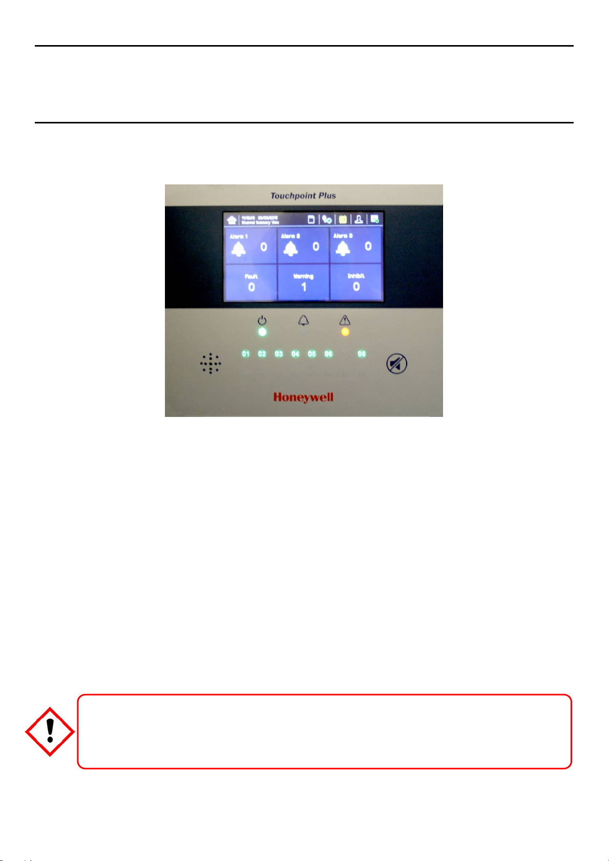
MAN0984_Iss 2_06/15 Touchpoint Plus
Technical Handbook
Operating Instruct ions
Chapter 6 – Touchpoint Plus Operating Instructions
6.1 User Interface General
Figure 32. Touchpoint Plus Controller User Interface
The User Interface panel (shown above) has:
• A color touchscreen for normal system operation, maintenance and configuration
• Power, Alarm / Fault and Inhibit state LEDs
• Active Channel (01 to 08) status indicators (Ch. 07 is not commissioned in this example)
• Accept (Silence) and Reset membrane button (Right side)
• Integral Alarm Buzzer (Left side)
Further System Interfaces consist of:
• Remote inhibit and remote reset terminals on the Main module
• One fixed relay and two configurable relays on Main Module for system Failure, Alarm and Inhibit
• Three dedicated alarm outputs for visual and audio alarms
• An optional SD Card
The interface software has two distinct modes of operation – Configuration Mode and Visualization Mode, and
access to certain functions is restricted by the use of password protected access levels. There are four
hierarchical access levels: View mode is available to all users while Operator, Engineer and Administrator
modes are password protected. Password holders can be assigned one access level only.
Direct sunlight, solvents, abrasives and sharp edged or metal tools may cause irreparable damage
to the LCD panel and membrane.
Use only damp cloths or computer screen wipes to clean it.
Caution
37
Page 44

MAN0984_Iss 2_06/15 Touchpoint Plus
Technical Handbook
Operating Instruct ions
6.2 Menu Items and Access Levels
The table below details the menu items and access levels for the User Interface. The password hierarchy is
Administrator, then Engineer, then Operator. Broadly speaking, the Administrator can commission modules
and configure channels, the Engineer can edit channel configuration and do calibration, and the Operator can
interact with the system during normal day-to-day operation such as acknowledging and resetting events.
A user can log in by selecting an access level and then inputting a password that is valid for that access level.
Note: LCD backlight timeout : 30 seconds, Menu timeout: 90 seconds, Authentication timeout:15 minutes.
There are two kinds of timeout in menu mode. One is “menu timeout” and the other is “authentication time
out”.
With “menu timeout”, the display will change to a higher menu and then back to the Channel Status screen if
there is no touch input for a pre-set time. The default menu timeout is 90 seconds, but this can be changed
using menu options Configuration>General>Timeout.
With “authentication timeout” the purpose is to cancel the login automatically when there is no activity for the
configured duration. If the user is logged out automatically they will be asked to log in again.
Items with a clock symbol timeout after 15 minutes of inactivity.
Key: = Allowed, = Denied, = Fixed timeout.
= sub-menu, = sub-sub-menu
Menu Item Admin Engineer Operator Others
Login
Menu Home
Information
System Info
Summary Info
Software Info
Parameter Info
Event History
Filter View
Export History
Trend/Plot
Channel Info
Board Info
Relay Status
Additional Status
Service Contract
Event History
Channel View Home
List View
Tile View
Summary View
Output View
Configuration
38
Page 45

MAN0984_Iss 2_06/15 Touchpoint Plus
Technical Handbook
Operating Instruct ions
Menu Item Admin Engineer Operator Others
Channel Settings
mA Input Channel
mV Input Channel
mA Output Channel
Relay Channel
Module Control Panel
General
Date / Time
Language
Service Contract
Home Settings
Timeout Setting
Log Interval and Threshold
Display Screen
Outputs
Dedicated Alarm Contacts
Buzzer Options
Security
Password
Remote Access (Buttons)
Config Manager
Import
Export
Maintenance
Reset Alarms / Faults
Reset All Peaks
Gas Calibration
Adjust mV Baseline
Service Mode
Electronic Adjustment
Safety Function
Reset to Defaults
Update System
Software
Language
Sensor Catalogue
Module Data
SD Card
Eject
39
Page 46

MAN0984_Iss 2_06/15 Touchpoint Plus
Technical Handbook
Operating Instruct ions
Menu Item Admin Engineer Operator Others
Format
Power Off
System Test
Force Relay
Force 4–20 mA
Relay C & E Matrix
Dedicated Alarm Contacts
Table 11. User Matrix
6.3 Touchscreen (Color Resistive)
The touchscreen is activated using a finger or a stylus (only). Do not use sharp or abrasive objects as they
may cause irreparable damage.
All interactions are single tap.
6.4 SD Card
The SD card is used to store the system event history. Touchpoint Plus logs all events and all changes to
input readings. A notification will be given when the SD card has less than 50 Mb of space remaining. If the
card is not replaced with an empty one, or if space is not freed up, a further notification will be given when it is
full and data is being overwritten.
The Touchpoint Plus accepts standard SD cards of 2 to 32 GB (FAT32). SD cards can be reformatted by
inserting the card into the SD card slot and using TPPL. Menu>Maintenance>SD Card>Format.
Note: The SD Cards must be unlocked. They must be formatted by TPPL, and they should be used for TPPL
data only. Stored data can be transferred or copied to a PC via a Card Reader and the card reused, but care must
be taken not to overwrite previously transferred data files, and a reliable backup system should be used to avoid
data loss.
Caution: Formatting the SD card will erase all existing data.
Note: The SD Card must remain inserted during normal system
memory is limited to a few minutes of events.
up
to avoid data loss.
operation as the on-board flash
When the card is full
it
should be replaced or space freed
40
Page 47

MAN0984_Iss 2_06/15 Touchpoint Plus
Technical Handbook
Operating Instruct ions
6.5 Normal Operation (Safety
During normal operation:
• The Touchpoint Plus system will collect sensor data every 250 ms from its Input / Output modules
• The Cause and Effect matrix will be evaluated every 250 ms, and commands sent accordingly to the
appropriate output channels. System response time is ≤1 s
• Any change in status of an I/O channel will be reported to the User Interface and logged in the event
history
• Events (Alarms, Faults, Inhibits, etc.) will be reported to the User Interface and logged in the event history
• Any fault within the system will activate the System Fault relay
• Any failure of the safety function i.e. due to major fault or power loss will activate the System Failure relay
6.6 Overview –
See Ch.12 Glossary
6.6.1 User Interface
The User Interface shows the current status of the Touchpoint Plus system as follows:
• Channel List – Display shows up to six inputs and events with automatic scrolling
• Channel Summary – Display shows total counts for alarm 1, alarm 2, alarm 3, fault, warning and inhibits
• Channel Tile – Display shows up to eight inputs and events
• Channel Output – Display shows up to eight output s and events
Key to examples below:
• Channel marking in red – one or more input channels are in Alarm
• Channel marking in yellow – one or more channels are in Fault
• Channel marking in orange – one or more channels are in Inhibit
• Channel marking in blue – one or more channels are in Warning
Tip: You can use the color-matched filter icons to list a series of specific event types.
Touchscreen Interface
of Icons for details about individual icons.
Scr
een
Functions)
41
Page 48
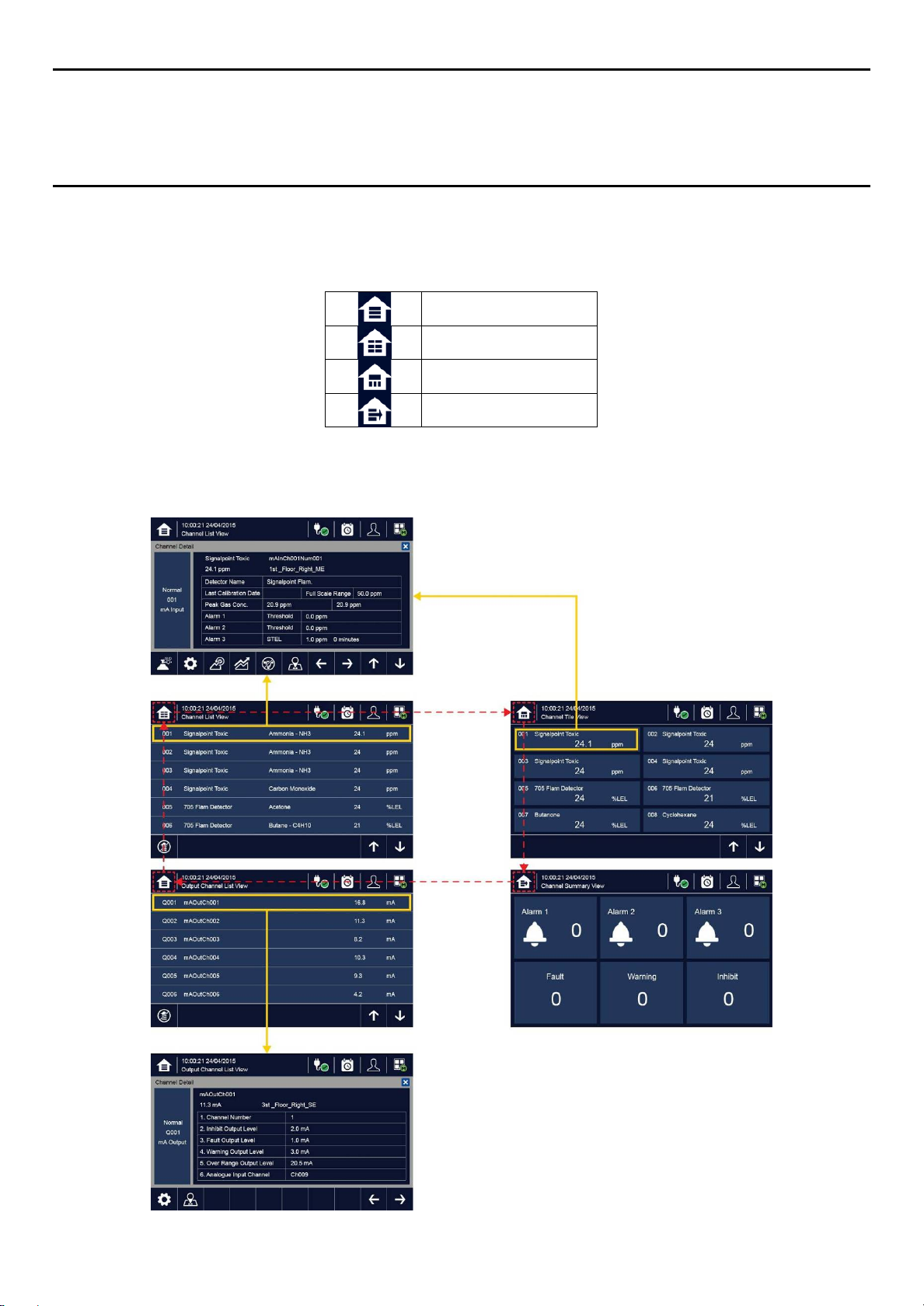
MAN0984_Iss 2_06/15 Touchpoint Plus
Technical Handbook
Operating Instruct ions
6.6.2 Navigation – Inputs and Outputs
The icons in the navigation toolbar are used to toggle through the User Interface
below.
Channel Input screen:
Channel detail screen.
If you touch an individual channel in the inputs and outputs screen, the Channel detail screen will be displayed as
shown below:
Screens
options, as shown in the table
List View
Tile View
Summary View
Output View
42
Page 49
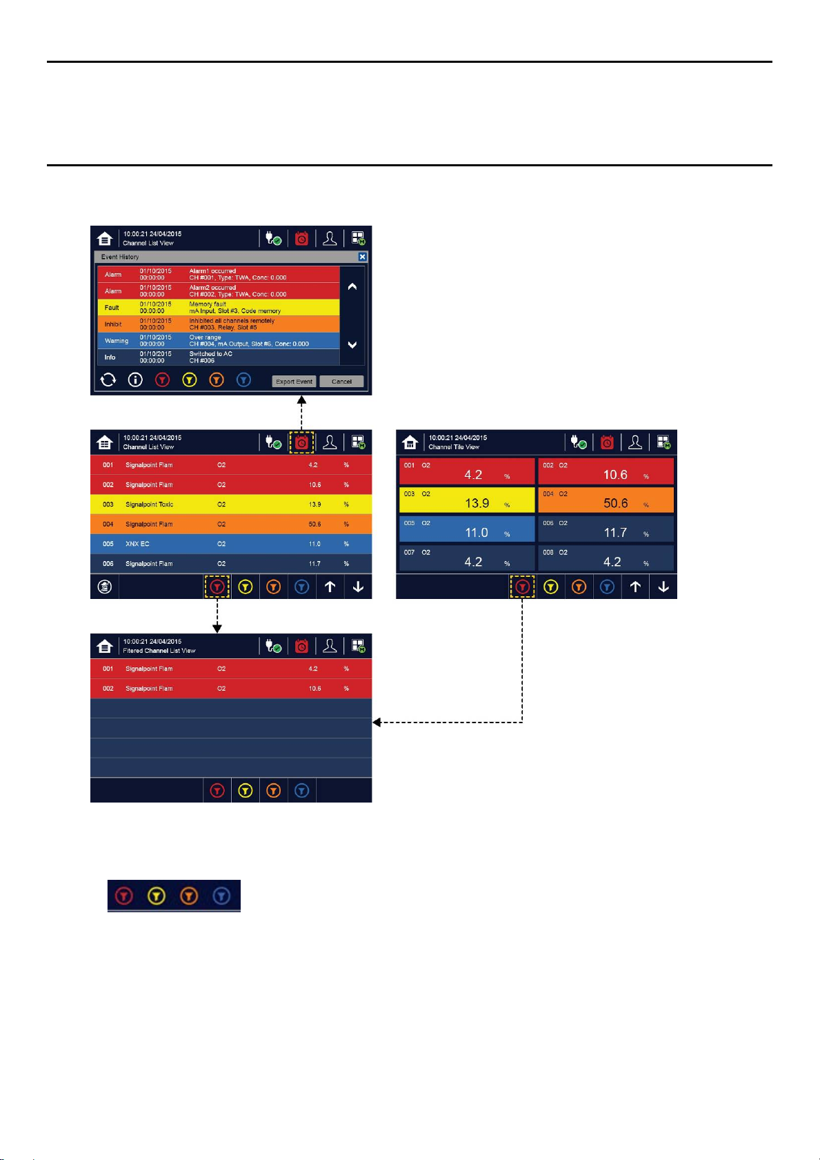
MAN0984_Iss 2_06/15 Touchpoint Plus
Technical Handbook
Operating Instruct ions
6.6.3 Navigation – Active
You can change the list type by using Filters from one of the Tile views:
Key to Filters:
• Red: Alarm
• Yellow: Fault
• Orange: Inhibit
• Blue: Warning
Events and Filtering
43
Page 50

MAN0984_Iss 2_06/15 Touchpoint Plus
Technical Handbook
Operating Instruct ions
6.6.4 Navigation – Menu
User must have the appropriate access level password to enter Maintenance, Configuration and System test
options.
Note: The system will log out after a set period of inactivity. (The default authentication timeout is 15 minutes,
but this can be changed in system settings.)
44
Page 51

MAN0984_Iss 2_06/15 Touchpoint Plus
Technical Handbook
Operating Instruct ions
6.6.5 Navigation – Active Access Level Icons
You must enter a valid password to login.
Note: The system will log out after a set period of inactivity. (The default authentication timeout is 15 minutes,
but this can be changed in system settings.)
6.7 Alarms
6.7.1 View active
Active alarms can be viewed:
1) From the Input screen, select the red filter icon:
The screen will display a list of the input channels with active Alarms, starting with the most recent event.
Unacknowledged alarms will flash, acknowledged ones will stay on. Touch the Accept button to acknowledge
the alarms.
Note: the display will show the channel ID location tag. If more than one alarm level has been triggered on the
same channel, a high priority alarm level will be shown.
alarms
No one is logged in
Operator is logged in
Service engineer is logged in
Administrator is logged in
6.7.2 Acknowledge
Note: Operator or higher level access is required.
Note: Accept and Acknowledge have the same meaning in this context.
An active Alarm can be acknowledged by logging in and touching the Accept button for >1 second. This will
acknowledge ALL active events and the channel LED and icon will stop flashing.
45
an active
alarm
Page 52

MAN0984_Iss 2_06/15 Touchpoint Plus
Technical Handbook
Operating Instruct ions
When an alarm is acknowledged the buzzer will be silenced and the alarm will stop flashing.
Note: If a Relay Output channel has the Alarm Update function enabled, the alarm will be ignored for the
Cause and Effect matrix once it is acknowledged.
6.7.3 Reset a latched
A latched alarm is one that cannot automatically reset itself when the triggering event has cleared.
Note: Operator or higher access level is required (optional, see Commissioning, Buzzer Activation and Button
Password Protection).
A latched alarm can be reset in three ways:
1) By logging in and touching the Reset button for >3 seconds. This will reset ALL latched alarms, faults and
warnings, provided that the triggering event has cleared. It will also reset any latched relay outputs.
2) By logging in and selecting Menu>Maintenance>Reset alarms/Faults. This will reset all latched events for
the channel, provided that the input signal has returned to Normal status.
3) By holding the Remote reset switch for >3 seconds. TPPL has the option of adding a remote acknowledge
/ reset switch up to 500 m away from the Controller. The remote r eset switch does not require a login so a
lockable switch should be used to prevent unauthorized access.
A gas detector may indicate that the gas concentration in its vicinity has dropped to a safe level, but this does not
mean that a dangerous atmosphere doesn’t persist elsewhere in that area. Do not reset the alarms until the area
alarm
Warning
has been confirmed to be safe or has been adequately ventilated.
6.8 Faults and W
6.8.1 View Faults and W
Detailed information about active Faults and Warnings can be viewed:
1) From the Input and output screen, select either the Fault (yellow filter) icon, or the Warning (blue filter)
icon. The screen will show a filtered list of only the active Faults or Warnings.
arnings
arnings
46
Page 53

MAN0984_Iss 2_06/15 Touchpoint Plus
Technical Handbook
Operating Instruct ions
6.8.2 Acknowledging an Active Fault or Warning
Note: Operator or higher level access is required.
Note: Accept and Acknowledge have the same meaning in this context.
An active fault or warning can be acknowledged by logging in and touching the Accept button for >1 second.
This will acknowledge ALL active events and the channel LED and icon will stop flashing.
6.8.3 Reset a Latched Fault or
Note: Operator or higher access level is required.
A latched fault or warning can be reset in three ways:
1) By logging in and touching the Reset button for >3 seconds. This will reset ALL latched alarms, faults and
warnings, provided that the event has cleared. It will also reset any latched relay outputs.
2) By logging in and selecting Menu>Maintenance>Reset alarms/faults. This will reset all latched events for
the channel, provided that the input signal has returned to Normal / within tolerance.
3) By holding the Remote reset switch for >3 seconds. TPPL has the option of adding a remote acknowledge
/ reset switch up to 500 m away from the Controller. The remote reset switch does not require a login so a
lockable switch should be used to prevent unauthorized access.
6.9 Inhibit
Note: Engineer or higher access level is required.
Input channels can be inhibited by logging in and by:
1) Selecting a channel and then touching the inhibit icon:
2) Using a Remote Inhibit input (locking switch).
To clear inhibits: log in, select the required channel and then select Clear Inhibit.
Note: An auto-inhibit cannot be cleared manually. Auto-inhibits may occur during calibration or warm-up,
when a transmitter is signaling Inhibit, or when an Inhibit delay time is running.
Note: Inhibit timeouts can be set by configuring the channel, as shown below:
Warning
47
Page 54
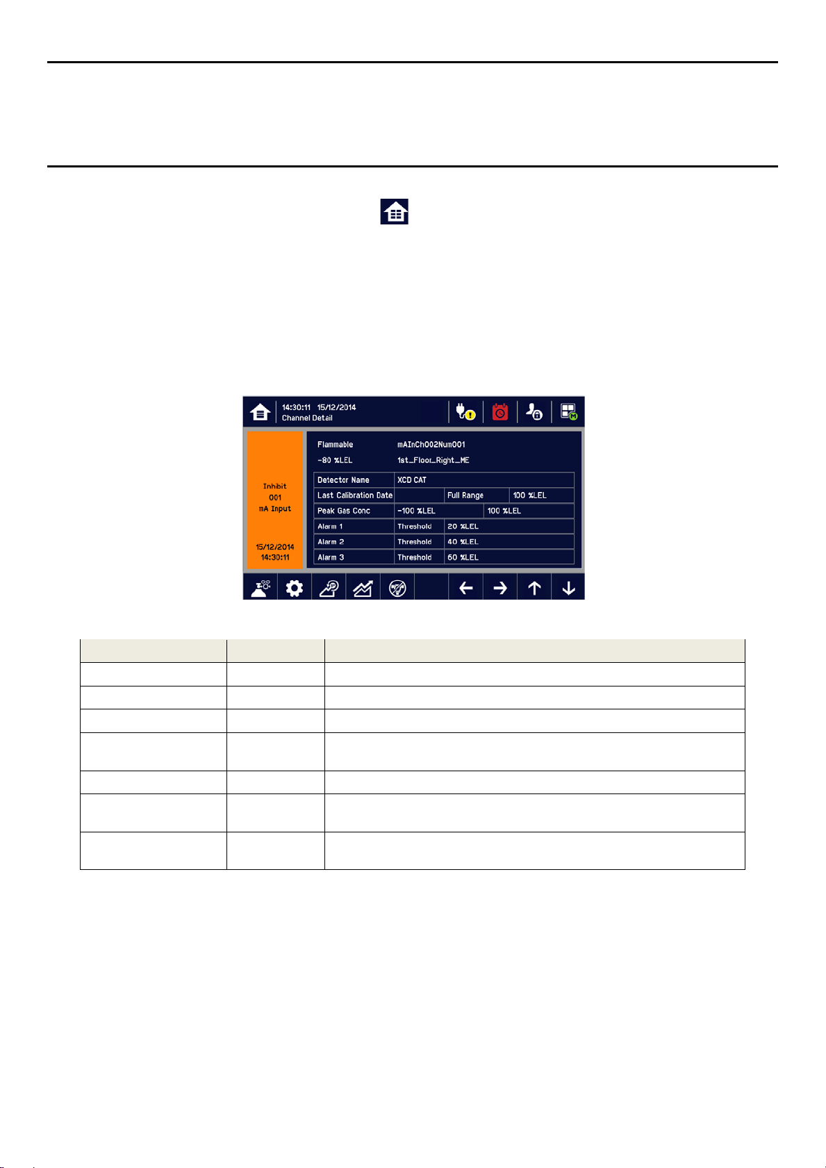
MAN0984_Iss 2_06/15 Touchpoint Plus
Technical Handbook
Operating Instruct ions
6.10 Viewing Input Channels and Input
From the Input screen, toggle the Home icon between Channel Tile>Channel Summary>Channel
Output.
1) From the Input screen, select Channel List or Channel Tile.
2) A list of all input channels is shown in order of channel ID. The channel ID, gas name, status, min/max
peak gas concentration and current reading will be shown.
3) The list can be filtered by status – Alarm, Fault, Inhibit, Warning or All.
4) Select a channel and the Channel detail screen will appear. Depending on access level, a number of
options will be shown:
Details
Function Access Level Comment
Calibration Engineer Option to calibrate the channel.
Channel configuration Engineer Change the input channel configurations.
Peak reset Engineer Reset peak reading of the channel.
Inhibit Engineer
Channel location Viewer Shows the physical position of the I/O Module and channel.
Trend Graph Viewer
Input Details Viewer
Inhibits the channel. On an inhibited channel, this option is Clear Inhibit.
See Normal Operation, Inhibit for more information.
Shows the trend graph for the channel. See Normal Operation, View
Trend Graph for more information.
Shows detailed information about the channel including Custom ID,
sensor and gas name, gas reading, configured alarms and alarm levels.
48
Page 55
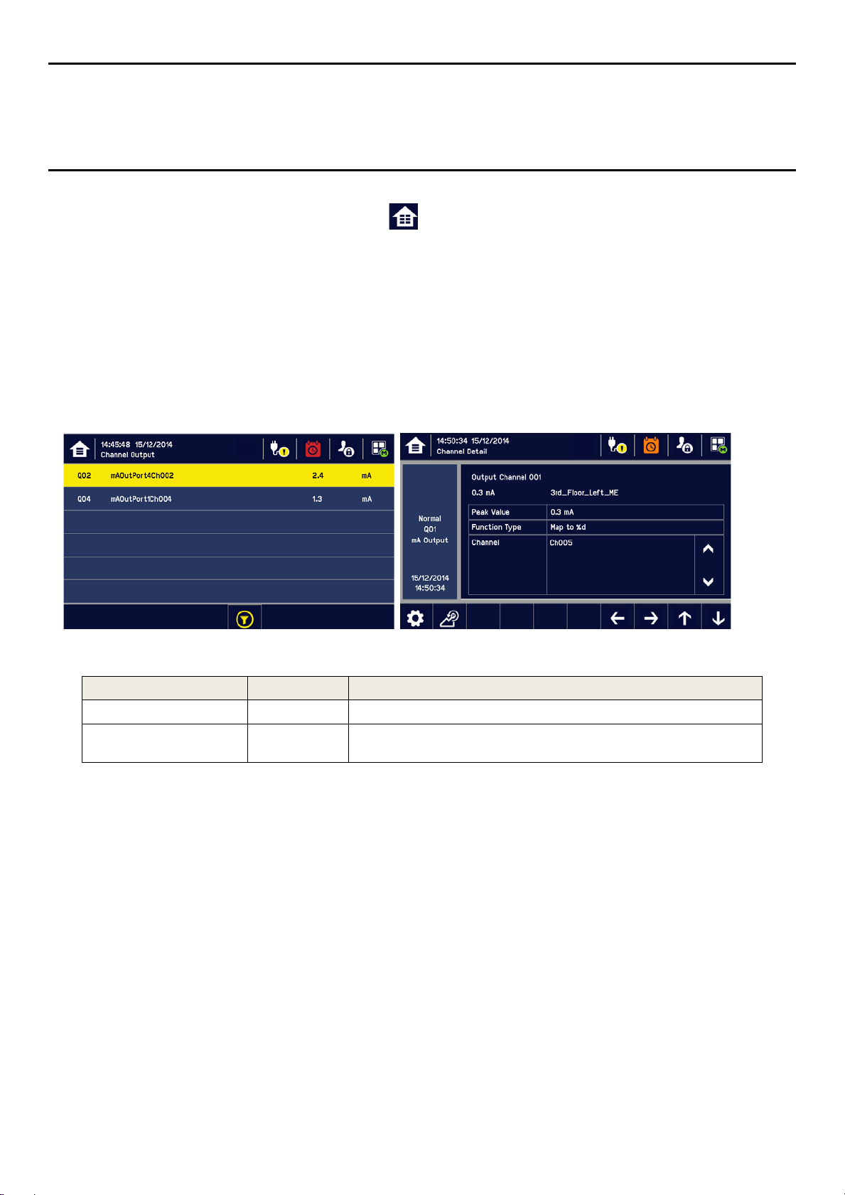
MAN0984_Iss 2_06/15 Touchpoint Plus
Technical Handbook
Operating Instruct ions
6.11 Viewing Output
From the Input screen, toggle the Home icon between Channel Tile>Channel Summary>Channel
Output.
1) From the Input screen, select Channel List or Channel Tile.
2) A list of all output channels is shown in order of channel ID. The channel ID, location tag and status are
shown.
3) The list can be filtered by status – Fault, Inhibit, Warning or All.
4) Select a channel and the Channel detail screen will appear. Depending on access level, a number of
options will be shown:
Channels
Function Access Level Comment
Linked input Channel Nr. Viewer Display an input channel number that is mapped to the output channel
Channel configuration Engineer
6.12 Viewing the Trend
The Trend graph is drawn using one minute average readings so it is not suited to viewing short-term signal
fluctuations.
To view the graph:
1) Select the Menu>Information>Trend/Plot.
2) Select the required channel, and then select Data range.
3) The trend graph will be displayed.
Note: Touchpoint Plus trend graph will retain the latest 8 hours of data but will be cleared after a power reset.
Note: Touchpoint Plus does not adjust automatically for daylight savings time so Touchpoint Plus will retain a
backup of the earlier data if the clock is backdated (i.e. when ending daylight savings time).
Graph
Change the output channel configurations: Inhibit, Fault, Warning, and
Over-range output level
49
Page 56

MAN0984_Iss 2_06/15 Touchpoint Plus
Technical Handbook
Operating Instruct ions
6.13 To View Event History and Export
The event history for the complete system can be viewed in date order (latest first). The history can be filtered
by Alarm, Fault, Inhibit, or Warning.
To view the event history: select Menu>Information>Event History, press the Event icon.
Note: Touchpoint Plus does not adjust automatically for daylight savings time so Touchpoint Plus will retain a
backup of the earlier data if the clock is backdated (i.e. when ending daylight savings time).
Active event data is saved to the SD card automatically if one is installed. The event history data can also be
exported to the SD card on demand.
To export the event history: select Menu>Information>Event History>Export Event.
Note: Make sure an SD card with sufficient empty space is installed before Exporting. See Checking the
Capacity of the SD Card below for more information.
Note: Microsoft Excel 2003 is limited to a maximum of 65,526 entries. If the report is larger than this a “file not
loaded completely” message may be generated. Microsoft Excel 2010 has a much larger capacity that should
be sufficient for all Touchpoint Plus generated reports.
Note: Touchpoint Plus does not adjust automatically for daylight savings time so Touchpoint Plus will retain a
backup of the earlier data if the clock is backdated (i.e. when ending daylight savings time).
6.14 Checking the Capacity of the SD Card
Select Menu>Information>Additional Status. This will show the size and remaining space on the inserted SD
Card. Please see the Maintenance chapter for details of how to replace the card.
The Touchpoint Plus accepts standard SD cards of 2 to 32 GB (FAT32).
6.15 Accessing the System Information and Service Contact Details
Select Menu>Information>System information>About to view details about the Firmware, Software and
serial numbers.
Select Menu>Information>Service Contact for details of how to access technical support.
6.16 System State Relays
The Main Module has three System State relays, rated at 30 VDC, 3 A or 250 VAC, 3 A, that activate under
the following conditions:
• One or both System-State relays can activate if there is any active alarm, fault, warning or inhibit in the
system (if configured).
• The System-Failure relay can activate if the safety function of the system is not operating, for example
due to a major fault or power loss.
50
Page 57

MAN0984_Iss 2_06/15 Touchpoint Plus
Touch for status
Touch for status
Technical Handbook
Commissioning
Chapter 7 – Commissioning
7.1 Introduction
This chapter explains several tasks that may be required during commissioning.
First time switch-on and Commissioning should only be carried out by a Honeywell engineer or someone with
System Administrator privileges who has been trained in accordance with this manual.
During First Time Switch On, it will be necessary to confirm or set the Date, Time and Language, to set new
passwords and delete the default password, and to program passwords tasks.
If the system was ordered from Honeywell Analytics, carry out Ch.7.5 Commission Input / Output Modules and
Ch.7.6 Channel Configuration for the input channels before proceeding with Ch.7.6 Channel Configuration for
the Relay Output channels and the mA Output channel.
7.2 First Time Switch On
Before switching power on, ensure that a qualified person has checked that the wiring is safe and conforms to
local regulations, and that all electrical connections are in accordance with Section 4. Also check that the
battery isolator switches are “On” if a backup battery is fitted.
Switch on power. You can use a multi-meter to check that the DC supply to the DC Connector block is
between 18 and 32 VDC (≥24 VDC when a battery is installed).
The system start up sequence may last for up to 5 minutes depending on the number of channels in use.
When start up is completed, Touchpoint Plus will display the Input screen, indicating the current status of the
system. The Channel list view is shown below:
Key to Icons:
Toggle to select screen layout
External mains power is provided.
External power is not connected.
Event History (Inhibit shown)
Login Status (Viewer)
Toggle auto-scroll on and off
Login Status (Admin)
Login Status (Engineer)
Login Status (Operator)
Menu
Filter Display (Inhibits shown)
51
Page 58

MAN0984_Iss 2_06/15 Touchpoint Plus
Technical Handbook
Commissioning
7.3 Date, Time and
Note: You should replace the CMOS battery if the time and date settings are not retained when power is
switched off then on again.
Note: Please regularly check the time and date settings and adjust if required.
7.3.1 How to Set or Change Date, Time and Language Settings:
1) Touch the Login icon in the navigation bar and a login prompt will ask for the access level and Password.
2) Login with the Service engineer access level. The initial default Password for all access levels is “TPPL”.
3) From the navigation bar select Menu>Configuration>General>Date/Time.
4) Set the date, time and display format as required.
5) Touch Finish.
Note: Touchpoint Plus does not adjust automatically for daylight savings time so Touchpoint Plus will retain a
backup of the earlier data if the clock is backdated (i.e. when ending daylight savings time).
Language Settings
7.4 Program Passwords
Note: Administrator level access is required to create or amend an Administrator or lower levels of password
access. Engineer level access can create or amend Engineer or lower levels of password access.
Note: Passwords are case sensitive.
The following rules apply to user passwords:
• Three password protected levels and one non-password level are available.
• The password must be at least 8 characters long.
• The password must contain a mix of letters, numbers and symbols.
• The password must contain upper and lower case characters.
1) Login with a valid engineer or administrator level.
2) Select Menu icon>Configuration>Security>Password.
3) Select an access level icon and input the currently logged in password, the new password, and confirm
the new password.
4) Touch Change.
Note: The default passwords will be replaced with the new passwords.
Please get help from your service contact if you forget a password. The details should have been entered in
the Touchpoint Plus software during commissioning. If not, please contact Honeywell Analytics Technical
Support, whose details are on the back page of this handbook.
For security reasons you must change the default Administrator, Engineer and Operator passwords at the
earliest opportunity and regularly thereafter.
At the very least you should keep a copy of the Administrator password in a safe place as it cannot be recovered
Careless password management can allow unauthorized access to the syste m that may cause security
problems that are the user’s responsibility.
Caution
if lost or forgotten.
52
Page 59
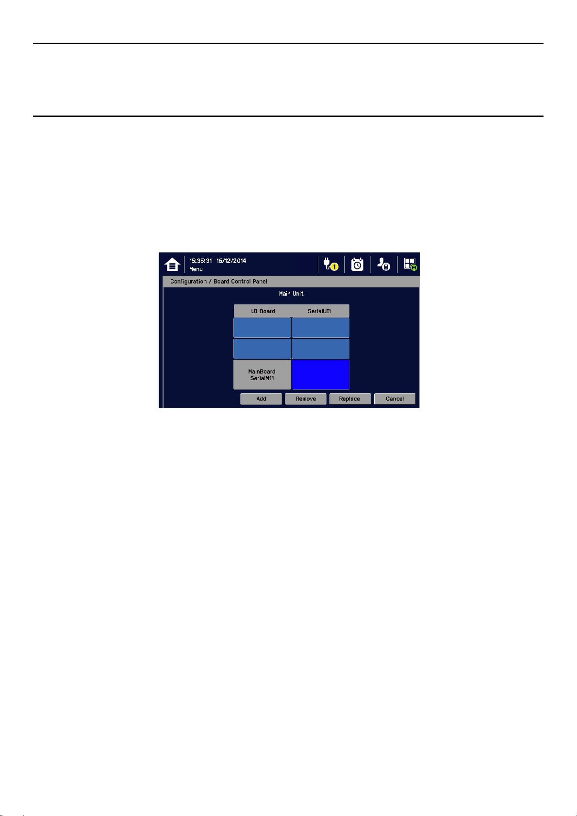
MAN0984_Iss 2_06/15 Touchpoint Plus
Technical Handbook
Commissioning
7.5 Commission Input / Output Modules
1) Login as an Engineer or Administrator.
2) Select Menu> Configuration>Module Control Panel.
3) Select an I/O module (a blue block) and touch “Add”. Select one of the listed I/O module types.
4) Repeat for other installed I/O modules.
5) To remove a module, select the Module on the screen and then touch “Remove”. To replace it, touch
“Replace”.
Note: Sky blue blocks show newly installed (i.e. uncommissioned) or decommissioned modules.
7.6 Channel Configuration
Note: Administrator or Engineer level access is required. Please refer to the section on User Interface, Access
Levels for details.
Note: There is no channel calibration reminder, and the user can disable the relevant calibration warning by
setting the calibration interval to zero. (See Ch. 7.6.2 Configuring a Channel and Ch. 7.6.3 Editing a
Configured Channel).
7.6.1 Introduction
Individual channels can be configured in two ways – either from the built in sensor catalogue (for Analogue
Input modules only), or by completing a full custom configuration.
When using the sensor catalogue, only the Channel number and tag must be manually entered and then the
rest of the configuration is populated automatically when a detector name and type are selected from the predefined list.
Note: You can always use the sensor catalogue as a starting point and then amend it afterwards (see
“Ch.7.6.3 Editing a Configured Channel” and “Ch. 14 Configurable Parameter Reference Guide).
To change any parameter, enter the new value and touch Apply to update the system. The system will then
return the value, which will be displayed on the screen, and the user must touch Update for the settings to
take effect. This requires the user to verify that the correct value has reached the system.
53
Page 60

MAN0984_Iss 2_06/15 Touchpoint Plus
Technical Handbook
Commissioning
New values can be entered in various ways:
• Free text (i.e. channel tag)
• Numeric keypad
• Check / uncheck a box (i.e. to toggle an alarm between latching and non-latching)
• Select an option by checking a radio button
• Select from a list of available options (i.e. channel number)
The configuration is designed to be simple to follow on the screen. However you can refer to Ch.13
Configurable Parameter Reference Guide to find detailed definitions of all the parameters, default settings and
available ranges.
7.6.2 Configuring a Channel (mA input and mV input channel)
Select the required configuration method, and follow the on-screen instructions. Refer to Ch.15 Configurable
Parameter Reference Guide for detailed information.
Note: You will need to have the required configuration information available before starting this procedure or
you risk the system timing you out and decommissioning the uncompleted channel and losing all your
unsaved changes.
To configure an individual channel:
1) Login as an Administrator or Engineer.
2) Select Menu>Configuration>Channel settings.
3) Select the required Module type.
4) Select a required channel and touch “Select”.
5) Select “Enable” for a required channel.
6) Select “Channel Number” and “Enter Channel Tag”.
7) Select a detector name and a sensor type to import all relevant configuration parameters from the Sensor
Catalog.
8) Edit the channel parameters.
9) Touch “Finish” if modification of channel settings is complete.
10) Check whether the channel settings are valid before making it take effect.
11) Touch “Apply”.
An I/O Module will be set into Configuration State if configuration update is attempted for any of its channels
(i.e. Commission Channel or Edit Configuration).
Configuration State means that all commissioned channels on the I/O Module are set into Inhibit state – i.e. the
input channels will not tr igge r any alarm s and output channels will not execut e a ny a ctions.
You should c onsider alternative safety measures when perfor m ing these proc e dures.
Caution – Ala rm Inhibit
54
Page 61

MAN0984_Iss 2_06/15 Touchpoint Plus
Technical Handbook
Commissioning
7.6.3 Editing a Configured Channel
Note: There is a 15 minute “no-input” timeout limit, after which you will be logged out and any unsaved
changes will be lost. It may also be necessary to return to the System Setup screen and set the module to
normal state.
To edit an already configured channel:
1) Login as an Administrator or Engineer.
2) Select the Menu>Configuration>Channel settings and then select an I/O module.
3) Select the required channel.
4) Select the screen that you want to edit (refer to previous sections of this manual).
5) Enter the required values in the field New Value and touch “Finish”.
6) Review all parameters are valid and touch “Apply”.
7) The system will return the new value; touch “Update” to confirm.
7.6.4 Editing mA Input Channel Settings (In Pictures)
55
Page 62
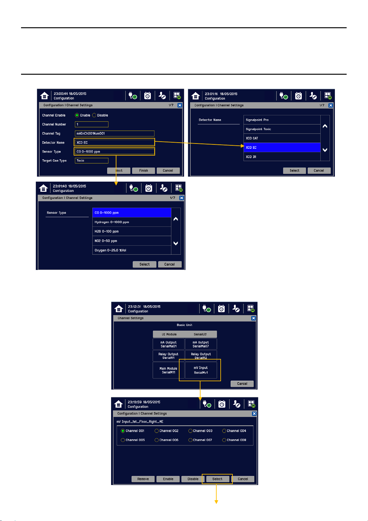
MAN0984_Iss 2_06/15 Touchpoint Plus
Please refer to Ch. 14 Compatible Sensors for a
Technical Handbook
Commissioning
list of available detectors.
You can also use the TPPL Sensor Catalog to
select listed gases, or you can enter “User gas”
details if your gas is not listed.
Please refer to Ch. 8.6 How to Update the
Sensor List for further inform at ion.
7.6.5 Editing mV Input Channel Settings (In Pictures)
56
Page 63
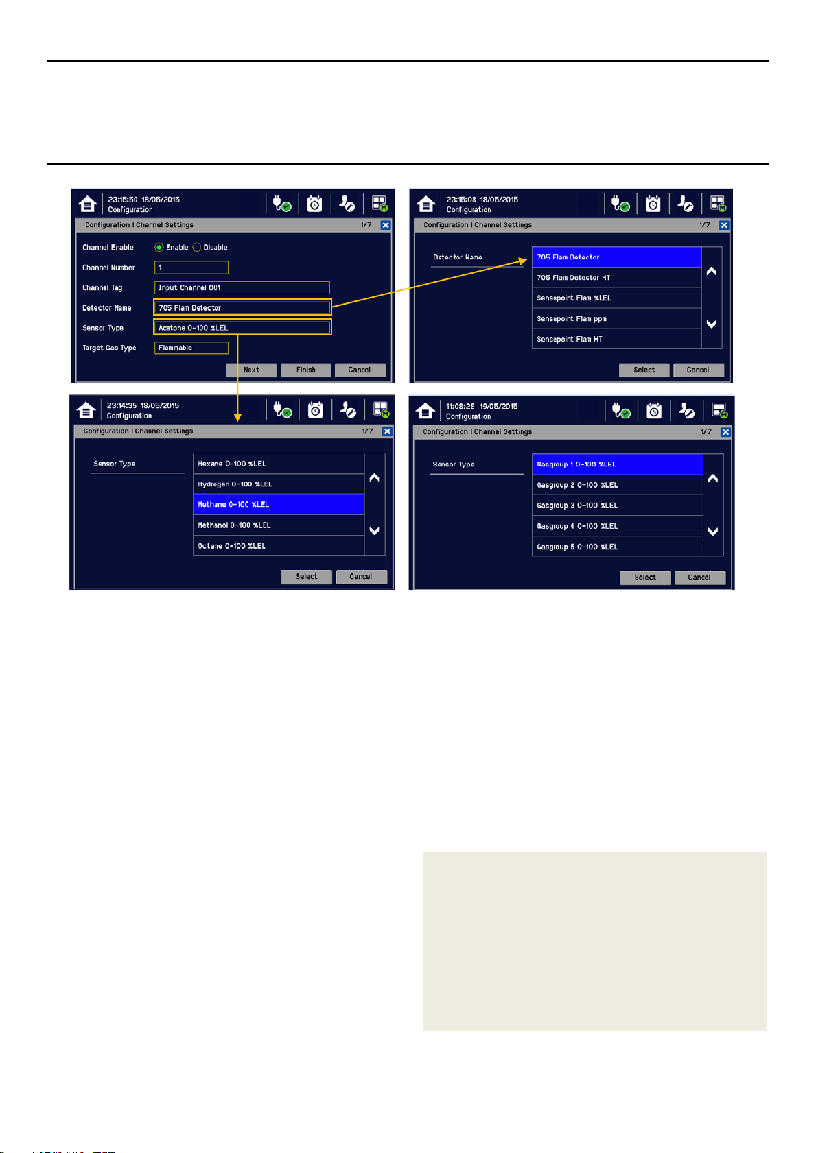
MAN0984_Iss 2_06/15 Touchpoint Plus
Technical Handbook
Commissioning
0
Please refer to Ch. 14 Compatible Sensors for a list of available detectors.
You can also use the TPPL Sensor Catalog to select listed gases, or you can enter Gas groups 1 to 8 if your
gas is not listed.
Please refer to Ch. 8.6 How to Update the Sensor List for further information.
Note: The gas selections available will vary with different types of sensors. Gases listed with a “-2” suffix are compliant with 60079-20-
1 LEL levels.
Note: Sensors must be recalibrated when selecting a new target gas.
Note: mV-bridge sensors are not suitable for use in oxygen enriched atmospheres (i.e. >21 %v/v). Oxygen deficient atmospheres (i.e.
<10 %v/v) may suppress sensor output.
7.6.6 Editing Relay Output Channel Settings
Prior to starting you should have completed configuring or editing all of the required input channels.
To configure an individual channel:
1) Login as an Administrator or Engineer.
2) Select Menu>Configuration>Channel settings.
3) Select the required Relay Output Module.
4) Select the required channel and touch “Select”.
5) Touch Enable.
6) Check/Uncheck the Vote Count Reduction
tick boxes and touch “Next”.
“Voting” is where an installation requires concurrent trigger
events from at least 2 detectors before it triggers a
response.
“Vote Count Reduction” is where the controller can be told
to ignore voting channels that are in Fault mode or Inhibit
mode or both, and will trigger an event when one or more
detectors (not in fault or inhibit) are triggered.
Non-voting detectors are not affected by Vote Count
Reduction.
57
Page 64

MAN0984_Iss 2_06/15 Touchpoint Plus
Technical Handbook
Commissioning
7) Set input channels and events to link the Relay Output channel and touch “Finish”.
8) Check that all edited settings are correct and select “Apply”.
9) Confirm that all edited settings are correct and select “Update”.
10) Repeat 4 to 9 for all required mA Output channels.
7.6.7 Editing Relay Output Channel Settings (In Pictures)
Key:
A1: Alarm 1
A2: Alarm 2
A3: Alarm 3
FLT: Fault
INHIB: Inhibit
WARN: Warning
58
Page 65

MAN0984_Iss 2_06/15 Touchpoint Plus
Technical Handbook
Commissioning
7.7 Data Logging
Set the Data Logging interval and threshold during configuration. A 0 %FSD threshold means that the TPPL
will log the gas concentration at the specified intervals without checking changes in gas concentration. In
contrast, a non-zero %FSD threshold setting will ignore fluctuations in low ambient gas concentrations and
only check for rises in gas above the threshold (i.e. safe) setting.
Leave the setting at 0 seconds if you don’t want to log gas concentration at the configured log interval.
However, if you do want to monitor changes, you should start with a low threshold setting and slowly increase
it by trial and error it if you get too many unnecessary warnings.
Note: A low gas concentration %FSD reading at one sensor only applies to the area immediately
surrounding that sensor, and may not indicate dangerous concentrations elsewhere in the room.
Always consider using multiple sensors at differing heights and locations, be aware that sudden
draughts can cause sharp rises in %FSD, and always take other safety measures (i.e. wearing
Honeywell personal gas alarms) before entering or working in the monitored location.
To set or change Data Logging:
1) Log in as an Administrator or Engineer.
2) Select Menu>Configuration>Log Interval & Threshold.
3) Select a box and enter the details using the touchpad.
4) Select “Finish”.
5) Make other changes or Log Out.
7.8 Touch Panel Configuration
To access the panel configuration:
1) Login as an Administrator or Engineer.
2) Select the Menu>Configuration>Display.
3) Select LCD Backlight Timeout and Brightness settings, or Start to calibrate the Touch Panel (see below).
4) Select Finish and return to the Configuration menu.
Parameter Name Default Setting Value Range Comment
Backlight time out 30 seconds 30 seconds to 10
minutes or
Always On
This is the time that the backlight will remain on after
the touchscreen is idle.
If a new event occurs, the backlight will come on and
will remain on as long as the event remains
unacknowledged.
7.8.1 How to Calibrate the Touch Panel
Calibrate the touch panel if the screen is not responding as expected.
To calibrate the screen:
1) Login as an Administrator or Engineer.
2) Select the Menu>Configuration>Display.
3) Touch “Start”.
4) Follow the instructions on screen.
5) Select “Finish” and return to the Configuration menu.
59
Page 66

MAN0984_Iss 2_06/15 Touchpoint Plus
Technical Handbook
Commissioning
7.9 Service Contact Settings
To set the Service contact:
1) Login as an Administrator or Engineer.
2) Select the Menu>Configuration>General>Service Contact.
3) Update the settings with your local service support contact details.
4) Select “Finish” and return to the Configuration menu.
7.10 Back up Configuration
It is recommended you back up the Touchpoint Plus configuration once commissioning is completed.
To back up the configuration:
1) If it is safe to do so, unscrew the handle security screws and open the enclosure door.
2) Ensure that a 2 to 32 GB (FAT32) standard SD Card with sufficient free space is inserted in the User
interface module.
3) Login as an Administrator or Engineer.
4) Select the Menu>Configuration>Config Manager>Export.
5) Enter file name for the backed-up configuration and touch “Finish”.
6) Touch “Export” to continue. The backup may take several minutes, and progress is shown on screen.
7) When backup is completed, remove the card and immediately fit a spare card with sufficient space to
record event data.
8) Close the enclosure door and tighten the two handle security screws.
9) Return the system to normal operation.
10) Transfer the backup data to a dated folder on a PC or digital device for safekeeping. The Configuration
backup file is stored on the SD Card in “\\CFG\TPP_CFG.bin”.
11) You can reuse the SD card once the data has been transferred to a PC or other device and deleted from
the card.
12) Restoring a configuration is the reverse process, i.e. Import instead of Export, but it can only be done by
an Administrator.
Note: Before attempting to restore from a saved configuration you must ensure that the current status is
exactly the same as it was when the backup file was exported. In other words the module installation status
and commissioning status must be exactly the same or the system will not import the configuration data.
60
Page 67

MAN0984_Iss 2_06/15 Touchpoint Plus
Technical Handbook
Commissioning
7.11 Calibrating mV Input Channels
7.11.1 Adjusting the mV Sensor Baseline
It is important to select “First Span” when calibrating a new or replacement sensor for the first time, and
“Span” for all calibrations thereafter.
It is important to select “Adjust mV Baseline” when calibrating a new or replacement sensor for the first time,
and “Span” for all calibrations thereafter. This also applies when either the detector type or sensor type is
changed during channel configuration, even though the sensor itself remains the same.
Doing this correctly allows a time window in which to safely organize replacement of nearly spent
catalytic bead sensors.
Doing it incorrectly may result in a spent sensor with no protection at all.
Gas readings may be generated during this procedure. Disable or inhibit any operations or actions that may
result from gas readings before starting this test.
For catalytic bead type detectors, the Analogue Input Modules form part of the measuring circuit. Therefore all
commissioned mV channels remain in Inhibit state until they are calibrated.
You should c onsider alternative safety measures when perfor m ing these proc e dures.
Caution – Ala rm Inhibit
1) Replace the catalytic bead sensor in accordance with its” manual.
2) Check the mV sensor wiring is undamaged and correctly connected.
3) Perform the next check under clean air.
4) Login as an Administrator or Engineer.
5) Select the Menu>Maintenance>Adjust mV Baseline and select a mV input channel.
6) Touch “Start”.
7) Check mV sensor type setting is correct.
8) Carry out the sensor calibration as shown in the next section (the mV input channel will be automatically
inhibited during this procedure).
7.11.2 Calibrating a mV Sensor Channel
To calibrate a mV input channel, follow the procedure below in combination with the relevant instructions in
the sensor manual.
1) Login as an Engineer.
2) Select Menu>Maintenance>Gas Calibration. Select the channel to be calibrated.
3) Select “Start”. Zero calibration and apply clean air to the sensor.
4) View the reading until it is stable, and then touch” Apply”.
5) Confirm the zero calibration result and then touch “Next”.
6) Enter the concentration of the span gas and touch “Start”.
7) When ready touch “Start” and apply gas to the sensor.
8) View the reading until it is stable, and then touch “Apply”.
9) Confirm that the gas reading is correct.
10) Remove the span gas from the sensor, and confirm that the gas reading has returned to zero (the mV
input channel will be automatically inhibited during the calibration procedure).
61
Page 68

MAN0984_Iss 2_06/15 Touchpoint Plus
Technical Handbook
Commissioning
7.12 Calibrate mA input channel loops
Where the sensor or transmitter has the facility, the mA loop should always be calibrated at the Touchpoint Plus
controller by forcing signal levels at the sensor / transmitter. Any gas calibration required must be carried out at
The Touchpoint Plus controller calibration should not be used to adjust for deficiencies in the sensor / transmitter
Caution: Ensure that any relay activation (drenchers, repeater alarms, etc.) is inhibited before starting this
test.
If the sensor is an Oxygen sensor that is not being used with a transmitter that has a force mA function, the
span gas should normally be air at 20.9% v/v Oxygen.
The Touchpoint Plus controller calibration should not be used to correct deficiencies in the sensor calibration;
instead carry out a gas calibration at the sensor according to the manufacturer’s instructions.
To calibrate the mA loop of an input channel, please follow the procedure below in combination with the
relevant instructions in the sensor manual.
gas calibration. Failure to observe this can result in significant accuracy errors.
the field device according to the manufacturer’s instructions.
Only trained technicians are authorized to carry out calibration.
Warning
1) Login as an Administrator or Engineer.
2) Select the Menu>Maintenance>Gas Calibration. Select the channel to be calibrated.
3) Select “Start” for Zero Calibration.
4) Apply a test gas to the sensor / field device so that it will generate a 4 mA signal.
5) View the reading until it is stable, and then touch “Apply”.
6) Select “Next” to move to the Span Calibration screen.
7) Enter the target span gas concentration and touch “Apply”.
8) Select “Start” for Span Calibration.
9) View the reading until it is stable, and then touch “Apply”.
62
Page 69

MAN0984_Iss 2_06/15 Touchpoint Plus
Technical Handbook
Maintenance
Chapter 8 – Maintenance
This chapter describes how to perform common maintenance operations and upgrades. The required
frequency of inspection and maintenance will depend on local site conditions and will need to be established
through experience. Please refer to IEC/EN 60079-29-2 or other local or national regulations for guidance on
establishing an appropriate maintenance routine.
If the relays are switching mains voltages, hazardous live terminals may be present within the
Read Chapter 2 Safety before carrying out any work on the system.
Relay Output Module even if the Touchpoint Plus system is isolated.
Ensure that all current is isolated and dissipated before touching live terminals.
Warning
Warning
8.1 Routine Maintenance
Ensure that relay activated output systems (i.e. emergency deluge / sirens etc.) are isolated before starting the
8.1.1 Weekly Checks
• Visually inspect all cables and conduits.
• Check for loose connections, security of attachment, and signs of damage.
• Wipe the Touchpoint Plus Controller with a soft damp cloth or PC Screen cleaner.
• Check for dust contamination.
• Periodically exercise the relays to confirm functionality (see Caution above).
While an Operator could Force a channel, an Engineer is required to isola te se r vices, carry out tests, Clear
For these reasons Operators are advised to carry out visual inspections and cleaning only, unless under the
Test outputs will be generated and relays will be activated during Cause and Effect Testing.
Do not use solvent or abrasives to clean any part of the Touchpoint Plus System.
Caution
test.
Caution
Force, and restore the system to full operational status.
direct supervision of the engineer.
Caution
63
Page 70

MAN0984_Iss 2_06/15 Touchpoint Plus
Technical Handbook
Maintenance
8.1.2 Exercising the Relays
Relay output channels can be tested by forcing the relays to an active state:
1) Ensure that relay activated output systems (i.e. emergency deluge / sirens etc.) are isolated before
starting the test.
2) Login as an Administrator or Engineer.
3) Select Menu>System test>Force Relay.
4) Select the Relay module to be tested, and toggle it off and on for the specific relay channel.
5) Check the relay out contact using a voltmeter.
6) Repeat steps 3 and 4 for all relay output channels.
7) Proceed to the next step.
8.1.3 Exercising the mA Output
mA output channels can be tested by forcing the mA output:
1) Ensure that relay activated output systems (i.e. emergency deluge / sirens etc.) are isolated before
starting the test.
2) Login as an Administrator or Engineer.
3) Select the Menu>System test>Force 4-20mA.
4) Select the channel to be tested and set the mA output value. Touch “Apply”.
5) Check the mA output level using an ammeter.
6) Repeat steps 2 and 4 for all relay output channels.
7) Select “Finish” when the tests are completed.
8.1.4 Exercising the Audio/Visual Alarm
Audio/visual alarm can be tested by forcing signal out:
1) Ensure that relay activated output systems (i.e. emergency deluge / sirens etc.) are isolated before
starting the test.
2) Login as an Administrator or Engineer.
3) Select the Menu>System test >Dedicated Alarm Contacts.
4) Toggle the alarm selector button off and on for each output (see below).
5) Check the voltage level using a voltmeter.
6) Select “Finish” when the tests are completed.
64
Ensure that the system is returned to normal operation once testing is complete.
Caution
Page 71

MAN0984_Iss 2_06/15 Touchpoint Plus
Technical Handbook
Maintenance
8.2 Testing the Touchpoint Plus System
8.2.1 Introduction
The Touchpoint Plus system has two test modes available, which together enable a full test of the system.
The test modes are:
• Field Inputs Test – tests all input channel devices without affecting any outputs.
• Cause and Effect Test – forces the Touchpoint Plus input channels to specific states to test that the
correct relay output channels are activated.
When any of the test modes is active, the System Failure relay will activate to indicate that the safety function
of the system is not operating. A Fault will be shown as an Active Event on the User Interface.
Once a test mode is active, the system will remain in test mode until the test is exited. The only exception is in
the case of a power cycle of the Touchpoint Plus system, when it will restart in normal mode.
All events generated while the system is in test mode will be logged in the event history. Therefore a record of
the testing can be generated once it is complete (see Normal Operation, Generate Reports).
The Touchpoint Plus system is not operational while in Test Mode, and all field device inputs will be ignored.
Ensure that alternative safety arrangements are maintained during test, and ensure that Test Mode is exited as
soon as testing is completed.
Test output conditions will be simulated and relays will be activated during the Cause and Effect Test.
Ensure that relay activated output systems (i.e. emergency deluge / sirens etc.) are isolated before starting the
Ensure that the system is returned to normal operation once testing is completed.
Warning
Caution
test.
Caution
8.2.2 Field Inputs Test
To carry out the Field Inputs Test:
1) Login as an Administrator or Engineer.
2) Set “Inhibit Input Channels”.
3) Supply test gas for the input channels.
4) System will display the gas reading and inhibit state.
5) Pre-configured Inhibit outputs (relays and mA output channels with output inhibit state) will be triggered
but all alarm outputs are inhibited.
65
Page 72

MAN0984_Iss 2_06/15 Touchpoint Plus
Technical Handbook
Maintenance
8.2.3 Cause and Effect Test
During this test, all field device inputs will be ignored by the Touchpoint Plus system. The Cause and Effect
matrix will be evaluated based on simulated input states and outputs will be generated.
Ensure that relay activated output systems (i.e. emergency deluge / sirens etc.) are isolated before starting the
This test has two purposes:
1) To verify that Cause and Effect matrix configuration is correct by forcing the state of the input channels to
various combinations.
Test outputs will be generated and relays will be activated during the Cause and Effect Test.
Caution
test.
2) To check that the output channels are configured correctly, including delay on/off times etc.
To use the Cause and Effect Test mode:
1) Login as an Administrator or Engineer.
2) Select the Menu>System Test>Relay C&E Matrix>Relay channel.
3) Select the channel to be tested.
4) The system will display a matrix of all the input channels that are linked to the output channel being
tested.
5) Select the input channel states that you wish to simulate, and click on “Simulate”.
6) Check that the relay output state is correct and touch “Finish”.
7) Repeat steps 2–6 for the next channel.
Ensure that the system is returned to normal operation once testing is complete.
Caution
66
Page 73

MAN0984_Iss 2_06/15 Touchpoint Plus
Gray: Mandatory modules that cannot be added removed
or replaced.
Technical Handbook
Maintenance
8.3 How to Replace a Faulty I/O Module
A faulty I/O module can be replaced with another of the same type, without needing to reprogram the
configuration. Touchpoint Plus will automatically copy over the configuration to the new module.
If the relays are switching mains voltages, hazardous live terminals may be present within the
Relay Output Module even if the Touchpoint Plus system is isolated.
Ensure that all current is isolated and dissipated before touching live terminals.
Antistatic Precautions are required to prevent severe damage to electronic components.
Anti–Static Precautions
Note: The new module must be the same type and the same number of inputs and outputs as the old module.
To replace a faulty module:
Warning
1) Switch off the Touchpoint Plus (Menu>Maintenance> Power off).
2) Isolate the power supplies and switch the battery to “Off” (if there is a back-up battery installed).
3) Disconnect the faulty module.
4) Replace the module.
5) Reconnect the module.
6) Switch the battery to “On” (if there is a back-up battery installed).
7) Switch on the TouchPoint Plus.
8) Login as an Administrator.
9) Select Menu>Configuration>Module Control Panel.
10) In the Board Control panel, select the empty blue block corresponding to the replaced module and touch
“Replace”.
Key to I/O Module colour
Yellow: A Module was added previously but cannot be
detected now (i.e. Module removed).
Light blue: Serial number or module type is not matched
(i.e. an I/O Module has been replaced).
Background colour: This module is installed.
67
Page 74

MAN0984_Iss 2_06/15 Touchpoint Plus
Module even if the Touchpoint Plus system is isolated.
Technical Handbook
Maintenance
8.4 How to Add a New I/O Module
The Touchpoint Plus system can easily be expanded by adding new I/O modules.
Note: A module that has previously been configured in one system cannot be added to another system,
unless it was correctly removed from the original system’s configuration.
1) Switch off the Touchpoint Plus (Select Menu>Maintenance> Power off).
2) Isolate the power supplies and switch the battery to “Off” (if there is a back-up battery installed).
3) Fit the new module of the required type to an empty slot, ensuring that that the module is the correct way
up and with the label towards you.
Antistatic Precautions are required to prevent severe damage to electronic components.
Anti–Static Precautions
4) Electrically connect the new module.
5) Switch the battery to “On” (if there is a back-up battery installed).
6) Switch on the TouchPoint Plus.
7) Login as an Administrator or Engineer.
8) Select the Menu>Configuration>Module Control Panel.
9) Select an empty block corresponding to the new module and touch “Add”.
10) Commission each channel in turn.
Note: See Ch.7 Commissioning for detailed instructions for further information.
8.5 How to Decommission and Remove an I/O Module
Note: Failing to follow this procedure correctly could render the removed module unusable.
To remove a module:
If the relays are switching mains voltages, hazardous live terminals may be present within the Relay Output
Antistatic Precautions are required to prevent severe damage to electronic components.
Anti–Static Precautions
Warning
1) Login as an Administrator or Engineer.
2) Select Menu>Configuration>Module Control panel.
3) Select the I/O module block that you want to remove, and touch “Remove”.
4) Switch off the Touchpoint Plus (Menu>Maintenance>Power off).
5) Isolate the power supplies and switch the battery to “Off” (if there is a back-up battery installed).
6) Electrically disconnect the module, and then remove it (see Ch. 8.4 above if you want to replace it with
another module).
7) Switch the battery to “On” (if there is a back-up battery installed).
8) Switch on the TouchPoint Plus.
68
Page 75
MAN0984_Iss 2_06/15 Touchpoint Plus
confirmed to be OK.
Technical Handbook
Maintenance
8.6 How to Update the Sensor Catalogue
From time to time, new versions of the sensor catalogue will be released containing updates and new
products from Honeywell Analytics.
To update the sensor catalogue in the Touchpoint Plus:
1) Download or copy the new sensor catalogue [TPP_CAT.bin] onto a device with an SD Card reader.
2) Create a new folder “CATALOG” on an empty 2 to 32 GB (FAT32) standard SD card and copy the
downloaded sensor catalogue file into it.
3) Remove the TPPP data SD card from the UI module and insert the sensor catalogue SD card.
4) Login as an Administrator.
5) From the System Status screen select Menu>Maintenance>Update system>SensorCatalog.
6) Confirm the update.
7) The sensor catalogue file will be updated. Note: The update may take several minutes.
8) Remove the sensor SD card and insert the data SD card.
8.7 How to Backup / Restore configuration
You should always take a new back up of the Touchpoint Plus system configuration after changes are made and
Note: The Touchpoint Plus system remains available during this procedure.
1) Ensure that an empty 2 to 32 GB (FAT32) standard SD Card is inserted in the User Interface module.
2) Login as an Engineer.
3) Select the Menu>Configuration>Config Manager>Export.
4) Enter a file name for the backed-up configuration and touch “Finish”.
5) Touch “Export” and, if the file name is valid, it will start the configuration backup process. The backup may
take several minutes, and progress is shown on screen.
6) When the backup is completed, remove the card and immediately fit a spare card to record event data.
7) Return the system to normal operation.
8) Transfer the backup data to a dated folder on a PC or digital device for safekeeping. The Configuration
backup file is stored on the SD Card in “:\\CFG\ [your file name]”.
Caution
9) You can reuse the SD card once the data has been transferred to a PC or other device and deleted from
the card.
Note: You cannot import configuration files if the I/O module configuration has changed since the last backup.
To restore the configuration:
1) Insert the SD card with “\\CFG\[your file name]” into the UI module SD Card slot.
2) Login as an Administrator.
3) Select the Menu>Configuration>Config Manager>Import and then choose your file.
4) Once the action is confirmed, the configuration restoration process starts and a progress message is
displayed. The process may take several minutes depending on the system size.
69
Page 76

MAN0984_Iss 2_06/15 Touchpoint Plus
Technical Handbook
Maintenance
8.8 How to Update Firmware
A Firmware update is usually only carried out to cure a fault or to give a system upgrade. Firmware updates
are usually optional and are not recommended if the system performs satisfactorily “as is”.
Firmware and software updates should normally be carried out only by a Honeywell trained Engineer or an
Engineer trained in accordance with this Technical Manual.
Alternative site safety arrangements should be made during this procedure as the Touchpoint Plus system is not
Before starting the firmware update, confirm that the new User Interface module firmware is compatible with both
available during firmware updates, and they may take several minutes to complete.
the installed I/O Module firmware and the Main module (see below).
Failure to do so may cause unexpected complications.
Caution
Caution
8.8.1 How to Check System Compatibility
1) Select Menu> Information>System information.
2) Note the firmware versions already installed.
3) Consult the Touchpoint Plus users support for compatibility information.
4) Contact your local service representative for advice if the new firmware is not compatible with the existing
Modules.
8.8.2 How to Update the Firmware
Caution: A power cycle of the Touchpoint Plus system is required during this procedure.
To update the Firmware:
1) Download the required Firmware onto a device with an SD Card reader.
2) The Firmware is contained in the file “\\FW\*.bin”. Copy this file onto a 2 to 32 GB (FAT32) standard SD
card (do not put it in a folder).
3) Ensure it is safe to do so, then unscrew the enclosure handle securing screws and pull the handle to open
the door.
4) Remove the installed SD Card. Limited event logging will carry on internally for a short while, but some
data may be lost if the update takes too long.
5) Insert the SD card containing the update file into the UI module.
6) Login as an Administrator.
7) Select the Menu>Maintenance>Update system>Software.
8) Select a Module and browse the appropriate firmware file in the SD card. Check the listed current and
update versions. Touch “Update” when ready.
9) When the updates are completed, the system will reboot automatically if required.
10) Repeat steps 8 and 9 for all other affected modules.
11) Remove the SD card and refit the event logging SD card.
12) Close the door and secure the access handle.
13) Check that the system status is OK and no faults or inhibits or errors are shown.
70
Page 77

MAN0984_Iss 2_06/15 Touchpoint Plus
Technical Handbook
Maintenance
8.9 How to Change the SD Card
Note: The system can accept standard SD cards from 2 to 32 GB (FAT32), and will provide a notification
when the card has less than 50 Mb of free space.
Caution: Do not leave the SD card out for too long or some event data may be lost.
To change the SD Card:
1) Select Menu>Maintenance>SD Card>Eject.
2) When prompted, remove the SD Card and insert a 2 to 32 GB (FAT32) standard card. Note the correct
orientation in the picture below.
3) Confirm that the screen shows the SD Card as being correctly inserted and that it has sufficient free
space (i.e. >50 Mb).
Figure 33. SD Card Location
71
Page 78

MAN0984_Iss 2_06/15 Touchpoint Plus
hydrocarbon / air mix. Always follow the sensor manufacturer’s data sheet when cross-calibrating sensors.
Technical Handbook
Maintenance
8.10 How to Calibrate mV Input Channels
Catalytic sensors should be calibrated periodically according to the manufacturer’s recommendations. This
should be a two-person job to avoid the controller timing out and losing the settings.
Note: To enable a calibration interval for the channel, edit the interval setting before starting calibration (see
Ch.7.6.2 Configuring a Channel and Ch.7.6.3 Editing a Configured Channel).
You should select First Span only when calibrating a new or replacement sensor for the first time. You then
adjust the mV Baseline, and then you should use Span for all calibrations thereafter (see Note below).
Note: Adjustment of the Baseline is only required when a mV channel is configured for the first time or when a
catalytic bead element is replaced. Once the Baseline is established it should not be adjusted for second or
subsequent gas calibrations, or until the next catalytic bead replacement.
To calibrate a mV Input Channel:
For greater accuracy, catalytic gas detectors should be calibrated using a certified gas/air mixture
equal to 50 %LEL of the actual target gas being monitored. Always refer to the sensor technical manual for
If you cannot obtain an exact or certified span gas match you can carry out a “cross-calibration” using a similar
Caution
detailed information.
1) Install or replace catalytic bead sensor elements according to their technical manual.
2) Login as an Administrator or Engineer.
3) Select the Menu>Maintenance>Adjust mV Baseline and select a mV input channel.
4) Select the Menu>Maintenance>Gas Calibration. Select the channel to be calibrated:
5) Select “Start” Zero calibration and apply clean air to the sensor:
72
Page 79

MAN0984_Iss 2_06/15 Touchpoint Plus
Technical Handbook
Maintenance
6) View the reading until it is stable, and then touch “Apply”.
7) Confirm that the gas reading is stable, and touch “Next”.
8) Enter the concentration of the span gas and touch “Start”:
9) When ready touch “Start” and apply gas to the sensor.
10) View the reading until it is stable, and then touch “Apply”. This may take 3 – 5 minutes, depending on the
gas type.
11) Confirm that the gas reading is correct.
12) Remove the span gas from the sensor, and confirm that the gas reading has returned to zero.
73
Page 80

MAN0984_Iss 2_06/15 Touchpoint Plus
Technical Handbook
Maintenance
8.11 Back up Battery Maintenance
Replace the battery pack with Honeywell Analytics part no. TPPLSIBB and the PCB CMOS battery with type
According to local laws and regulations the battery installed within your product should be disposed of separately
from household waste. When the battery reaches its end of life, take it to a collection point designated by local
Note: The DC 24 V battery pack has an integral 15 A over-current protection fuse, and will accept a nominal
input charge of 24 – 32 VDC. (<24 VDC will not charge the battery to the level required for backup power.)
Lithium batteries may cause severe injury or death if put in the mouth or swallowed.
Always keep them away from children and dispose of them as hazardous waste.
Use of other batteries may present a risk of fire or explosion.
Danger
CR2032 only.
Danger
Caution
authorities.
8.11.1 Recommended Scheduled Maintenance
• Visually inspect the Touchpoint Plus Battery and (as the enclosure is open) all cabling.
• Check for signs of damage, deterioration, or loose connections.
• Periodically check that the cooling vents have not become obstructed.
8.11.2 How to Replace the Battery Pack
The battery pack has circuitry that puts it into sleep mode to save power when it is not connected and running.
Connecting it to a powered-up Touchpoint Plus causes the battery to change to active mode and it will
function normally after a short booster charge.
To replace the battery pack:
1) Ensure that the atmosphere is below flammable levels.
2) Leave the Touchpoint Plus Controller powered on.
3) Unscrew the two locking handle security screws and open the enclosure.
Touchpoint Plus shall not be operated with the access door unsecured when in Normal mode.
Failing to secure it properly will risk fire or explosion and will invalidate Regulatory Approval.
Danger
4) Switch the backup battery On/Off switch to Off (Fig. 31) to isolate the battery.
5) Replace the battery pack with Honeywell Analytics Part No. TPPLSIBB.
74
Page 81

MAN0984_Iss 2_06/15 Touchpoint Plus
Technical Handbook
Maintenance
6) Switch the backup battery On/Off switch back to On.
7) Close the enclosure door and secure the handle with the two security screws.
Figure 34. Battery On/Off Switch and Battery Connector
Note: Ensure that the battery On/Off switch is in the On position before closing the access door or the backup
battery will not work when it is most required.
8.12 Return to Factory Default Settings
If required, the system Administrator can return the TPPL Controller to its Factory Default settings.
To reset the Touchpoint Plus to its Factory Default settings:
1) Log in as an Administrator.
2) Select Maintenance>Service Mode>Reset to Default.
Returning TPPP to its Factory Default settings will initialize all user settings i.e. mA and m V Input channel
calibrations, Relay and mA Output settings etc.
Your TPPP system may become inoperative until it is reconfigured correctly (see Ch. 7 Commissio n i ng), and you
should put alternative safety arrangements in place until the system is returned to normal operation.
Passwords are not changed when resetting to Factory Default settings.
Warning
3) If required, recommission the Touchpoint Plus system (Ch. 7 Commissioning).
75
Page 82

MAN0984_Iss 2_06/15 Touchpoint Plus
Technical Handbook
Troubleshooting
Chapter 9 – Troubleshooting
Problems are signaled by an error code shown on the control panel display. The error is recorded in the event
log and the screen can be cancelled once the fault is corrected.
The error messages are explained in Chapter 16: Fault Codes.
Contact Honeywell Analytics Technical Support if an error appears repeatedly, if it cannot be cleared, or if it is
not listed in Chapter 16: Fault Codes.
before carrying out any work on the gas detection systems.
Warning
Read Chapter 2 Safety
9.1 Calling for Technical Support.
Please contact Honeywell Analytics Technical Support if your problem cannot be resolved or if you need
additional help. You can find our contact details on the rear cover of this manual.
To assist the Honeywell Helpdesk in giving you technical support, it would be helpful to have the following
information ready:
• Your Company contact details and a contact name and department.
• The system model type, i.e. Touchpoint Plus, and its serial number. These can be found on the system
identification label.
• The software version found under the System Info menu option key.
• Details of the difficulty that you are experiencing.
• Error message and code numbers that were shown on the display screen.
To assist with the fault diagnosis you may be asked to send a copy of your event log by email.
76
Page 83

MAN0984_Iss 2_06/15 Touchpoint Plus
Technical Handbook
Technical Specifications
Chapter 10 – Technical Specifications
10.1 Environmental
Sealed enclosures are rated IP65 NEMA 4x, and can be installed indoors only in a Pollution Degree 2, 10 to
95 %RH Non-Condensing environment that affords total protection from rain, snow and direct sunlight.
Operating Temperature
Storage Temperature
Operating Humidity (closed)
10.2 User Interface and Main Module
LCD Touch Screen Type
Front Display
Output Relays
Dedicated Audio and Visual alarm
Remote Terminals Optional remote acknowledge, reset and inhibit
-10 °C to + 55 °C
-25 °C to + 60 °C
10 to 90 %RH (non-condensing)
7” TFT Color LCD with LED Backlight (resistive touch screen)
800 x 480 pixels (WVGA) Resolution
Active area 155.08 mm (H) x 86.92 mm (V)
Green Power LED
Red Alarm LED
Yellow Fault/inhibit LED
Alarm Mute /Reset Push Button
Alarm Buzzer (Sound Level: 70 dB at 1 m)
Two configurable and one fixed System State Relays:
5 A @ 250 VAC, 5 A @ 30 VDC (non-inductive load)
Four outputs to external devices
Supply voltage Vs (18 – 32 VDC) –1.8* VDC (max), max 300
mA per channel
*Voltage drop at ambient temperature
77
Page 84

MAN0984_Iss 2_06/15 Touchpoint Plus
Technical Handbook
Technical Specifications
10.3 I/O Modules
10.3.1 mA Input Module
Description
Sensor Configuration
Signal Measurement Range 0 – 24 mA
Sense Resistance
Module Power Consumption
Field Device Power Supply Vmax (—)
Field Device Power Supply Power max
(single channel)
Field Device Power Supply Power max
(eight channels)
Maximum cable length for mA Input
loop (Rloop)
10.3.2 mV Input Module
Description
Current Range
Drive method
Maximum Power Consumption
Maximum Loop Resistance
Electrical Connections
2,4 and 8-channel Analogue Input Module for 2-wire or 3-wire
4 – 20 mA detector signals
2-wire or 3-wire current source
66 Ω
Max 0.4 W (Excludes power to mA detector)
Supply voltage Vs (18 – 32 VDC) –*1.8 VDC (max)
*Voltage drop in Touchpoint Plus at T
15 W
40 W
Rloop = (Vcontroller – 1.8 VDC – Vdetector min) / Idetector
Maximum Cable run length = Rloop / (Ω per meter).
Example: Vcontroller = 24 VDC, TPP Voltage drop = 1.8
VDC, Vdetector = 18 VDC (18 to 32 VDC), Idetector = From
detector specification.
2,4 and 8-channel Analogue Input Module for mV-Bridge
signals
200 mA
Constant current
19 W (including power to detector @ loop resistance of 36 Ω)
36 Ω at 200 mA (including sensor)
3-wire mV–Bridge
.
a
10.3.3 mA Output Module
Description
Module Power Consumption (Max.)
Sensor Configuration
Signal Measurement Range 0 – 20 mA (4 – 20 mA = 0 – 100% scale)
Loop Resistance
4-channel Analogue Output Module for 2 wire 4 – 20 mA
signals
3 W (700 mA loop resistance @ 20 mA output)
2-wire current source, Isolated current loop output
33 – 700 Ω
78
Page 85

MAN0984_Iss 2_06/15 Touchpoint Plus
Technical Handbook
Technical Specifications
10.3.4 Relay Output Module
Description
Power Consumption Maximum
Relay Contacts (~ / — )
Relay Operation
10.4 Power Supplies
10.4.1 External Supplies
SMPS Power Supply
AC Input Voltage Range (~)
DC Input Voltage Range (—)
Input Frequency Range (~)
Output Voltage (—)
Dimension
10.4.2 Backup Battery
12-channel Relay Output Module incorporating 12 single pole
change over (SPDT) relays
2.6 W (with all relays energized)
5 A @ 250 VAC / 5 A @ 30 VDC
Individually configurable for – normally energized / de-
energized operation
156 W
AC 110/220 V ±10 % of nominal (manual switching)
DC 18 – 32 V SELV Supply
AC 50 – 60 Hz ± 6 %
DC 24 V
199 x 98 x 38mm (L x W x H)
Description
Electrical Connection
Dimensions/Weight
Operating Temperature
Operating Humidity
Storage Life Limitations
Storage Lifetime without re-charge
Input Current (charging) (—)
Output Voltage (when supplying) (—)
Maximum Input Current
Maximum Output Current
Current Limit Protection
22.2 V Lithium - ion Battery, 2600mAh
6 X 3.7 VDC in series
124.8 x 78.9 x 29.2 mm, 425g
0 – 50 °C
10 to 90% RH (non-condensing)
1 Year: –20 °C to +25 °C (–4 °F to +077 °F)
3 months: –20 °C to +45 °C (–4 °F to +113 °F)
1 month: –20 °C to +60 °C (–4 °F to +140 °F)
1 year
DC 24 – 32 V @ 0.38 mA max.
17.4 – 25.2 VDC
250 mA
5 A
FUSE 15 A (non-replaceable)
79
Page 86

MAN0984_Iss 2_06/15 Touchpoint Plus
Technical Handbook
Technical Specifications
10.5 Enclosures
10.5.1 Wall Mount Enclosure
Material
Cable Gland Plug
Environmental Protection
Operating Humidity
Mounting Bracket
Enclosure Weight
Dimension
PC ABS
PG16
IP65 (when fully closed and locked), NEMA 4x indoors
10 to 90 %RH (non-condensing)
W 423 x D 325 x H 16.5 mm – 1.5 Kg (approx.)
8.5 Kg (approx)
426 mm x 300 mm x 156 mm (16.9 ins x 11.8 ins x 6.2 ins)
80
Page 87

MAN0984_Iss 2_06/15 Touchpoint Plus
WARNING
température
WARNING
métrologique suivant la directive ATEX.
WARNING
Technical Handbook
Certifications
Chapter 11 – Certifications
11.1 EC declaration of conformity
A full EC declaration of conformity is available on either original hardcopy or electronic file (Honeywell
Analytics website). This document lists the European Standards with which Touchpoint Plus complies.
Only the combustible gas detection portion of this instrument has been assessed for performance in
Seulement la partie détection de gaz explosif de cet équipement a fai t l’objet de tests de performance
CSA performance is only valid when connected to Honeywell Model 705 Catalytic Gas Detectors or
La performance en conformité avec la CSA est valide uniquement lorsque l’appareil est connecté aux
détecteurs de gaz catalytiques Honeywell modèle 705 ou à des détecteurs de gaz 4 – 20 mA dûment
accordance with the ATEX Directive.
AVERTISSEMENT
suitably approved 4 – 20 mA Gas Detectors.
AVERTISSEMENT
approuvés.
11.2 National and International Certificates of Compliance
The Touchpoint Plus Process Control Equipment holds the following National and International Certificates
and Certification Codes:
Title Standards Certificates
Ingression protection IP65 and NEMA 4X
Electrical Safety
EMC/RFI EMC Directive (EN 50270:2015)
Battery Pack
Performance ISA 12.13.01 and CSA C22.2 No.152
Copies of the certificates are available on request.
Note 1: OEMs are responsible for ensuring that their systems are certified in accordance with these tables
and any 3rd-party requirements.
Température ambiante : elle dépend des composants assemblés, vérifier individuellement les plages de
Ambient temperature: Dependent on components fitted, check individual rating plates.
UL/IEC/EN 61010-1, UL 508
CSA C22.2 No.61010-1/No.142
UN 38.3 (IEC 62133), UL 2054, UL 60950-1
CSA C22.2 No.60950-1-07
AVERTISSEMENT
UL File E466771
UL File E470577
UL File MH60522
UL File EXXXXXX
(To Be Determined)
81
Page 88

MAN0984_Iss 2_06/15 Touchpoint Plus
Technical Handbook
Replacement Parts and Optional Extras
Chapter 12 – Replacement Parts and Optional Extras
The following replacement parts and optional extras are available to order, but Honeywell Analytics cannot
accept responsibility for their incorrect fitment or use.
All Honeywell supplied replacement parts are covered by the standard Honeywell warranty service.
With the exception of SD Cards, the equipment listed below is only to be installed or replaced by the
Manufacturer’s trained personnel, or by competent persons trained in accordance with the Manufacturer’s
installation instructions.
Description Part Number
SD Card (2 to 32 GB) FAT32 standard format Local purchase
SD Card (8GB) TPPLOSDC
Backup battery pack TPPLSIBB
Input Module 2 Channel mA TPPLSMAAI2
Input Module 4 Channel mA TPPLSMAAI4
Input Module 8 Channel mA TPPLSMAAI8
Input Module 2 Channel mV TPPLSMAVI2
Input Module 4 Channel mV TPPLSMAVI4
Input Module 8 Channel mV TPPLSMAVI8
Output Module 4 Channel mA TPPLSMAAO4
Output Module 12 Channel Relay TPPLSMAROC
Main Module TPPLSMPM
SMPS (150 W,110 / 220 VAC) TPPLSSAM
Back Plane PCB Assembly TPPLSBPM
UI PCB TPPLSDPM
Touch Screen LCD TPPLSLTSM
External Strobe M-700123
Cable gland TPPLOGLD
Metal grounding for cable gland TPPLOMGND
Wall Mounting Bracket TPPLOWMB
82
Page 89

MAN0984_Iss 2_06/15 Touchpoint Plus
Technical Handbook
TPPL Configurati on Infor m ati on
Chapter 13 – TPPL Configuration Information
The following table shows how your TPPL part number relates to your TPPL configuration, and it is this part number that provides valuable information to Technical
Support if you need additional help.
Your TPPL part number can be found on the TPPL rating plate.
Part No.
See
Example
below.
Example
Part
Number:
Product
Name
TPPL
TPPL B A W A4 S 4 B N N N
Unit Type Power
A = 110/220
VAC
B = Base
Unit
D = 18 - 32
VDC
Mounting
Type
W = Wall
Mounted
Table 12. TPPL Part Number Configuration Chart
Input
Options
A2 = 2ch mA
Input
V2 = 2ch mV
Input
A4 = 4ch mA
Input
V4 = 4ch mV
Input
A8 = 8ch mA
Input
V8 = 8ch mV
Input
Relay
Options
S = 12
relays
D = 24
relays
N = No
Relay
Output
Options
4 = 4ch mA
Output
8 = 8ch mA
Output
N = No mA
Output
Battery
B = Backup
Battery
N = None
External
Comms
N = No N = No N = No
Web Server Certification
83
Page 90
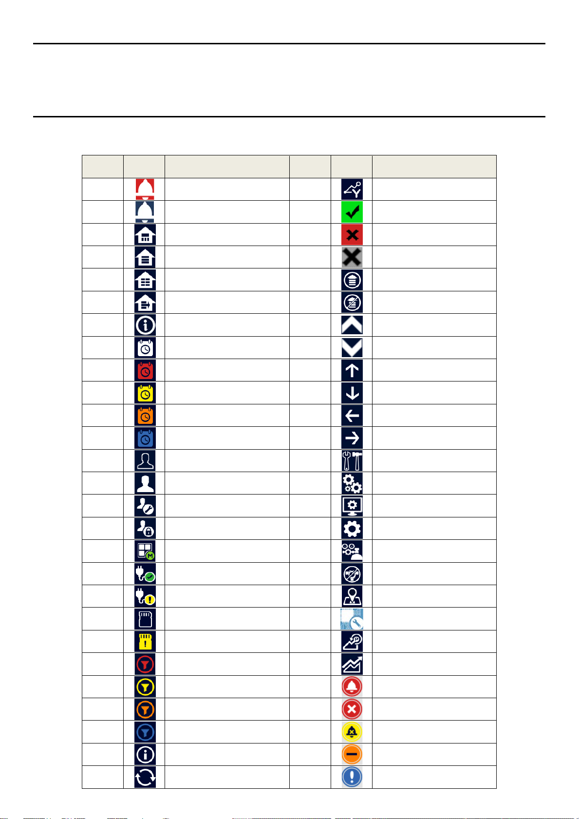
MAN0984_Iss 2_06/15
Glossary of Icons
Chapter 14 – Glossary of Icons
#
1
2
3
4
5
6
7
8
9
10
11
12
Icon Description
Summary View Alarm
Summary View Normal
Summary View
List View
Tile View
Output View
Information Menu
History Information
Event History Alarm
Event History Fault
Event History Inhibit
Event History Warning
#
28
29
30
31
32
33
34
35
36
37
38
39
Icon Description
Trend Graph
Processing Ok
Processing Fail
Cancel
Scroll
Stop Scrolling
List Up
List Down
Bottom Up
Bottom Down
Bottom Left
Bottom Right
13
14
15
16
17
18
19
20
21
22
23
24
25
No One Logged In
Operator Logged In
Engineer Logged In
Administrator Logged In
Menu Select
Power Connected
Battery Backup State
SD Card Logging Data
SD Card Fault
Alarm Filter
Fault Filter
Inhibit Filter
Warning Filter
40
41
42
43
44
45
46
47
48
49
50
51
52
Maintenance Menu
System Setting Menu
Configuration Menu
Configuration
Calibration
Inhibit
Channel Location
Base Line Adjust
Peak Reset
Trend
Alarm Pop Up
Error Pop Up
Fault Pop Up
26
27
84
Filter Information
Filter Refresh
53
54
Inhibit Pop Up
Warning Pop Up
Page 91

MAN0984_Iss 2_06/15
Glossary of Icons
#
55
56
57
Icon Description
Low Battery Warning
Critically Low Battery
Power Off View
#
58
Icon Description
Gas Calibration
85
Page 92

MAN0984_Iss 2_06/15 Touchpoint Plus
Technical Handbook
Compatible Sensors
Chapter 15 – Compatible Sensors
The following table lists Honeywell supplied gas sensors that are known to be compatible with Touchpoint
Plus.
Customer supplied 3rd Party sensors may be used, but Honeywell is unable to support them or guarantee their
performance.
Honeywell Gas Detectors
Midas Series 3000
Optima Plus Signalpoint Pro
RAEGUARD 2 PID Signalpoint Toxic
Satellite XT XCD CAT
Searchline Excel LR XCD EC
Searchline Excel MR XCD IR
Searchline Excel SR XNX CAT
Sensepoint RFD XNX EC
Sensepoint Toxic XNX IR
Please refer to the respective sensor data sheets for more detailed information.
Table 13. TPPL Gas Detectors
Note: Touchpoint Plus is not currently approved as a fire or flame detection system, but this list will be
expanded when its flammables capability is fully tested and certified.
86
Page 93

MAN0984_Iss 2_06/15 Touchpoint Plus
Technical Handbook
Configurable Paramet er Ref er ence Gui de
Chapter 16 – Configurable Parameter Reference Guide
Parameter Name Parameter Description Applies to Read/Write
Alarm 1 Enable
Alarm 1 Function
Alarm 1 Level Alarm 1 threshold concentration
Alarm 1 Trigger Alarm trigger option. 0 = Rising 1 = Falling
Alarm 2 Enable Alarm enable/disable. 0 = Disabled 1 = Enabled
Alarm 2 Function
Alarm 2 Level Alarm 2 threshold concentration
Alarm 2 Trigger Alarm trigger option. 0 = Rising 1 = Falling
Alarm 3 Enable Alarm enable/disable. 0 = Disabled 1 = Enabled
Alarm 3 Function
Alarm 3 Level Alarm 3 threshold concentration
Alarm 3 Trigger Alarm trigger option. 0 = Rising 1 = Falling
Alarm enable/disable.
0 = Disabled 1 = Enabled
Type of alarm function. Default is threshold. 0=Threshold, 1=STEL,
2=TWA
Type of alarm function. Default is threshold. 0=Threshold, 1=STEL,
2=TWA
Type of alarm function. Default is threshold. 0=Threshold, 1=STEL,
2=TWA
All
All R/W 0 n/a
All
All
All
All R/W 0 n/a
All
All
All
All R/W 0 n/a
All
All
Default
Value
R/W 1 n/a
R/W 20 %FSD conc.
R/W
R/W 1 n/a
R/W 40 %FSD conc.
R/W
R/W 1 n/a
R/W 60 %FSD conc.
R/W 0 n/a
1 for O
1 for O
, 0 for
2
other gases
, 0 for
2
other gases
Measurement
units
n/a
n/a
Alarm hysteresis is to avoid the alarm from frequent on/off when the gas
Alarm Hysteresis
Alarm Latch
Cal Interval Recommended calibration interval in days. Default is 6 months
87
reading is close to the alarm threshold. When clearing the gas alarm,
the gas reading should go below gas alarm threshold hysteresis.
The hysteresis is defined in % of Full range (Default 2%)
Alarm latch option. Alarm will be continued until manual user reset if
latching is enabled.
0: Disabled, 1: Enabled
All
All
All
R/W 2 %FSD
R/W 1 n/a
R/W 180 days
Page 94
MAN0984_Iss 2_06/15 Touchpoint Plus
Technical Handbook
Configurable Paramet er Ref er ence Gui de
Parameter Name Parameter Description Applies to Read/Write
Default Range Full scale range
Detector Name Detector name
Formula Gas Name Formula for the target measuring gas
Gas Name Target gas name
Gas Over Range Limit
Gas Type
Gas Under Range Limit Negative reading limit All R/W -7 %FSD conc.
Gas Unit
Inhibit Timeout Inhibit timeout in minutes. 0 means permanent inhibit All R/W 10 minutes
Lower Zero Dead Band
Max Range Maximum configurable measuring range
Over-range gas concentration limit. This parameter is used to generate
over-range warning.
Toxic (0), O2 (1), Flammable (2)
Set automatically by Gas Type
Measurement unit Strings:
%, ppm, %LEL, %VOL, mA
Lower deadband range. The gas concentration within the deadband
limit will be suppressed to default base concentration. I.e. if the gas
concentration is between the (default base concentration - lower
deadband) and (default base concentration + upper deadband), then
the reading will be the default base concentration.
All
All
All
All
All R/W 110 %FSD conc.
All R/W per target gas n/a
All
All
All
R/W
R/W per detector n/a
R per target gas n/a
R/W per target gas n/a
R per target gas n/a
R/W -2 %FSD conc.
R
Default
Value
Measurement
units
conc.
conc.
Min Range Minimum configurable measuring range
Resolution Index of display resolution for gas relevant parameters
Sensor Name
Signal Fault Max Upper mA input signal range to detect the fault reported by the detector.
Signal Fault Min Lower mA input signal range to detect the fault reported by the detector.
88
Sensor name consists of gas name, full scale range and measurement
unit.
All
All
All
mA sensor
only
mA sensor
only
R
R/W per target gas n/a
R per target gas n/a
R/W 1.1 mA
R/W 0 mA
conc.
Page 95

MAN0984_Iss 2_06/15 Touchpoint Plus
Technical Handbook
Configurable Paramet er Ref er ence Gui de
Parameter Name Parameter Description Applies to Read/Write
Signal Inhibit Max
Signal Inhibit Min
Signal Over Range Limit
Signal Under Range Limit
Signal Warning Max Upper mA input signal range to detect remote warning from the detector
Signal Warning Min
Span Calibration Conc. Target span gas concentration. Normally it is 50 %FSD. All R/W 50 %FSD conc.
STEL Interval* STEL period in minutes. The catalogue is using index instead.
TWA Interval* TWA period in hours. The catalogue is using index instead.
Upper Zero Dead Band
Upper mA input signal range to detect whether detector is inhibited or
not.
Lower mA input signal range to detect whether detector is inhibited or
not.
Upper allowable limit for the input signal from the sensor/detector. If the
signal is out of this limit, the I/O board will generate an input signal fault.
Lower allowable limit for the input signal from the sensor/detector. If the
signal is out of this limit, the I/O board will generate an input signal fault.
Lower mA input signal range to detect remote warning from the
detector.
Upper deadband range. The gas concentration within the deadband
limit will be suppressed to default base concentration. In other words if
the gas concentration is between (default base concentration - lower
deadband) and (default base concentration + upper deadband), then
the reading will be default base concentration.
mA sensor
only
mA sensor
only
All R/W
All R/W
mA sensor
only
mA sensor
only
mA sensor
only
mA sensor
only
All
R/W 2.2 mA
R/W 1.8 mA
R/W 0 mA
R/W 0 mA
R/W 15 minutes
R/W 8 hours
R/W 2 %FSD conc.
Default
Value
22 mA or 200
%FSD for mV
100 %FSD or
0 mA for mV
Measurement
units
mA / mV
mA / mV
Zero Range Zero gas concentration. It is normally zero.
All
R/W 0 conc.
*Note: STEL/TWA selection only applies to mA input sensors except for Oxygen mA input sensors.
89
Page 96

MAN0984_Iss 2_06/15 Touchpoint Plus
Technical Handbook
Fault Codes
Chapter 17 – Fault Codes
Code Display in Event History Description
1
Communication fault [B/D Type], Pos: xx, Code: xxx Internal communication fault
2
Memory fault [B/D Type], Pos: xx, Code: xxx internal memory fault
3
Catalogue memory fault Catalogue memory corrupted
4
Internal hardware fault [B/D Type], Pos: xx, Code: xxx Internal hardware fault
5
Sensor circuit fault CH: xx, [B/D Type], Pos: xx, Code: xxx Sensor circuit fault
6
Supplied voltage fault [B/D Type], Pos: xx, Code: xxx Supplied voltage fault
7
Internal software fault [B/D Type], Pos: xx, Code: xxx Internal software failure
8
— Reserved
9
Sensor fault CH: xx, [B/D Type], Pos: xx, Code: xx Sensor fault (including signal range fault)
10
mA Output Error CH: xx, [B/D Type], Pos: xx Analogue output mismatched
11
Relay Output Error CH: xx, [B/D Type], Pos: xx Relay not controlled
12
Detector In Fault CH: xx, [B/D Type], Pos: xx
13
Battery Fault Pos: xx Backup battery fault
IO B/D Not Matched [B/D Type], Pos: xx,
14
Prev: xxx, Current: xxx
15
Negative Reading CH: xx, [B/D Type], Pos: xx, Conc: xxxx
16
Fault Cleared CH: xx, [B/D Type], Pos: xx, Code: xx Fault self-cleared
17
Reset all faults Manually reset all faults
Remote fault notified by a detector
(depending on fault signal range)
I/O board not matched or present
Cell is producing a negative reading
(depending on gas under-range limit)
90
Page 97

MAN0984_Iss 2_06/15 Touchpoint Plus
Technical Handbook
List Of Figures
Chapter 18 – List of Figures
Figure 1. Quickstart Guide Label (Not to Scale) 8
Figure 2. SMPS Voltage Warning Label (Removed During Installation) 8
Figure 3. Protective Earth (Ground) Point 8
Figure 4. Equipment Earth (Ground) Point 8
Figure 5. Internal Label Positions 8
Figure 6. Touchpoint Plus Wall-Mounted Controller 13
Figure 7. Typical Installation Options 13
Figure 8. TPPL Controller Exploded View 14
Figure 9. System Layout Before Installation 17
Figure 10. Undoing the Security Screws and Opening the Enclosure 19
Figure 11. Installation Clearance Measurements 20
Figure 12. Wall Mounting Template 20
Figure 13. Wall and Plate Mounting Points 20
Figure 14. Fixing Orientation When Using the Optional Mounting Plate 21
Figure 15. Switched Mode Power Supply (SMPS) Connections 23
Figure 16. Connections for DC 24 V Supply 24
Figure 17. Connecting the Touchpoint Plus and Optional Expansion Unit to a Mains Supply 26
Figure 18. Dedicated Alarm Circuit Connections 28
Figure 19. Optional Remote Reset and Inhibit Switch Connections 28
Figure 20. Three Wire Device Powered by a mA Input Module 29
Figure 21. Three Wire Device Powered by an External Source 30
Figure 22. Two Wire Device Powered by a mA Input Module 30
Figure 23. Two Wire Device Powered by an External Source 30
Figure 24. Two Wire Device Barrier Device Powered by a mA Input Module 31
Figure 25. Grounding for Screened Cable with Armour and with Metal Junction Box and Sensor 31
Figure 26. Grounding for Screened Cable, No Armour, with Metal Junction Box and Sensor 31
Figure 27. Grounding for Screened and Armoured Cable with Plastic Junction Box and Sensor 32
Figure 28. Grounding for Screened Cable with Plastic Junction Box and Sensor 32
Figure 29. Catalytic Detector Connections 33
Figure 30. mA Output Module Connections 34
Figure 31. Relay States 36
Figure 32. Touchpoint Plus Controller User Interface 37
Figure 33. SD Card Location 71
Figure 34. Battery On/Off Switch and Battery Connector 75
91
Page 98

MAN0984_Iss 2_06/15 Touchpoint Plus
Technical Handbook
List of Tables
Chapter 19 – List of Tables
Table 1. Power Supply (SMPS RS–150–24) Electrical Ratings 15
Table 2. System Power Calculations 15
Table 3. System Weights 16
Table 4. System Dimensions 16
Table 5. Regional Power Cable Colours 23
Table 6. Main Module Connections 27
Table 7. mA Input Module Connections 29
Table 8. mV Input Module Connections 33
Table 9. mA Output Module Connections 34
Table 10. Relay Output Module Connections 35
Table 11. User Matrix 40
Table 12. TPPL Part Number Configuration Chart 83
Table 13. TPPL Gas Detectors 86
92
Page 99

Please Note:
intended to form the basis of a contract
Issue 2_05/2015
© 2015 Honeywell Analytics
Find out more at
www.honeywellanalytics.com
Contact Honeywell Analytics:
Europe, Middle East, Africa
Life Safety Distribution AG
Javastrasse 2
8604 Hegnau
Switzerland
Tel: +41 (0)44 943 4300
Fax: +41 (0)44 943 4398
gasdetection@honeywell.com
Customer Service:
Tel: 00800 333 222 44 (Freephone number)
Tel: +41 44 943 4380 (Alternative number)
Fax: 00800 333 222 55
Middle East Tel: +971 4 450 5800 (Fixed Gas Detection)
Middle East Tel: +971 4 450 5852 (Portable Gas Detection)
Americas
Honeywell Analytics Inc.
405 Barclay Blvd.
Lincolnshire, IL 60069
USA
Tel: +1 847 955 8200
Toll free: +1 800 538 0363
Fax: +1 847 955 8210
detectgas@honeywell.com
www.honeywell.com
Asia Pacific
Honeywell Analytics Asia Pacific
#701 Kolon Science Valley (1)
43 Digital–Ro 34–Gil, Guro–Gu
Seoul 152–729
Korea
Tel: +82 (0)2 6909 0300
Fax: +82 (0)2 2025 0328
India Tel: +91 124 4752700
analytics.ap@honeywell.com
Technical Services
HAexpert@honeywell.com
EMEA:
US:
ha.us.service@honeywell.com
ha.ap.service@honeywell.com
AP:
www.honeywell.com
While every effort has been made to ensure accuracy in this
publication, no responsibility can be accepted for errors or
omissions. Data may change, as well as legislation and you are
strongly advised to obtain copies of the most recently issued
regulations, standards and guidelines. This publication is not
H_MAN0984_EMEA
3011M5012 HAA150030
 Loading...