

Honeywell Touchpoint 1 Technical Manual

Technical Manual
Touchpoint 1
Single Channel Gas Detector Controller
TP1MAN Issue 3 Apr 06 (MAN0630) 1

TP1MAN Issue 3 Apr 06 (MAN0630) 2
Safety
Safety
This manual supports software revision 1.06.
Ensure that this Technical Manual is read and understand BEFORE installing/operating/
maintaining the equipment.
Pay particular attention to Warnings and Cautions.
All document Warnings are listed here and repeated where appropriate at the start of the
relevant chapter(s) of this T echnical Manual. Cautions appear in the sections/sub-sections of the
document where they apply.
WARNINGS
Touchpoint 1 is designed for installation and use in indoor safe area
non-explosive atmospheres. Installation must be in accordance
with the recognized standards of the
appropriate authority in the country concerned.
Before carrying out any work ensure local regulations and site procedures
are followed.
Access to the interior of the controller, when carrying out any work, must only be
conducted by trained personnel. Switch off and isolate the power supply
to the controller, or obtain a hot work permit, when access is required. Take any
necessary precautions to prevent false alarms.
The detectors/sensors that the controller connects to may be used for gas
detection in hazardous atmospheres. Refer to the individual detector/sensor
instructions for their details.
TP1MAN Issue 3 Apr 06 (MAN0630) 3

Information
Information
Honeywell Analytics can take no responsibility for installation and/or use of its equipment if this
is not done in accordance with the appropriate issue and/or amendment of the T echnical Manual.
The reader of this Technical Manual should ensure that it is appropriate in all details for the exact
equipment to be installed and/or operated. If in doubt, contact Honeywell Analytics for advice.
The following types of notices are used throughout this Technical Manual:
WARNING
Identifies a hazardous or unsafe practice which could result in
severe injury or death to personnel.
Caution Identifies a hazardous or unsafe practice which could result in
minor injury to personnel, or product or property damage.
Note Identifies useful/additional information.
Every effort has been made to ensure the accuracy of our documents, however, Honeywell
Analytics can assume no responsibility for any errors or omissions in our documents or their
consequences.
Honeywell Analytics greatly appreciates being informed of any errors or omissions that may be
found in the contents of any of our documents.
For information not covered in this document, or there is a requirement to send comments/
corrections about this document, please contact Honeywell Analytics.
Honeywell Analytics reserve the right to change or revise the information supplied in this
document without notice and without obligation to notify any person or organization of
such revision or change. If information is required that does not appear in this document,
contact the local distributor/agent or Honeywell Analytics.
TP1MAN Issue 3 Apr 06 (MAN0630) 4

Contents
Contents
Safety 3
Information 4
Introduction 7
Enclosure 8
Display Module 8
Terminal Module 8
General 8
Installation 9
Location 9
Dimensions 10
Mounting 11
Controller Components 12
Power 13
Cabling 13
Wiring 14
Zareba Sensepoint Gas Detector Connections 17
Generic Gas Detector Connections 22
Maximum Cable Lengths 23
Operation 25
Powering Up 25
Information on the Display 26
Status Indications 26
Control Buttons 31
Menus 32
Using Menus 32
Displaying Menus 32
Navigating Menus 32
Accepting Menu Choices 32
Cancelling Operations/Choices 33
Alarms 33
Commissioning 34
3-wire mV Bridge 34
2-wire 4-20 mA Sink 36
3-wire 4-20 mA Source 37
TP1MAN Issue 3 Apr 06 (MAN0630) 5

Contents
User Settings 38
Gas Units and Range 38
Zero and Span 40
Event History 41
Alarm Levels and Relay Action 42
Time and Date 44
Power Source 45
Default Configuration 45
mV input detector 46
4-20 mA input detector 46
Maintenance 47
General Maintenance 47
Troubleshooting 48
System Configuration Check Sheet 49
System Review Check Sheet/Record 50
Parts 51
Touchpoint 1 Controllers 51
Spares 51
Specifications 52
General 52
Environmental 52
Inputs 53
Outputs 53
Warranty 54
TP1MAN Issue 3 Apr 06 (MAN0630) 6
Installation
Installation
WARNINGS
Touchpoint 1 is designed for installation and use in indoor safe area
non-explosive atmospheres. Installation must be in accordance
with the recognized standards of the
appropriate authority in the country concerned.
Before carrying out any work ensure local regulations and site procedures
are followed.
Access to the interior of the controller, when carrying out any work, must only be
conducted by trained personnel. Switch off and isolate the power supply
to the controller, or obtain a hot work permit, when access is required. Take any
necessary precautions to prevent false alarms.
The detectors/sensors that the controller connects to may be used for gas
detection in hazardous atmospheres. Refer to the individual detector/sensor
instructions for their details.
Caution When carrying out any work ensure that executive outputs from the
controller are inhibited in order to prevent false alarms.
This chapter provides the following information about installing Touchpoint 1:
• where to locate the controller, its dimensions and how to mount it
• how to access the interior of the controller, see page 12
• cabling and wiring, see page 13 and page 14
Note It is recommended that a local fused power feed spur, with lockout switch, is used.
Earth/Ground loops or poor screening are the most common cause of false alarms.
Proper installation, using appropriate earth techniques improves:
• resistance to radio frequency interference (RFI), e.g. mobile phones and walkie-talkies
• resistance to induced signals from magnetic fields (EMC), e.g. high power cables
and switch gear.
Location
Touchpoint 1 can only be installed in indoor safe areas.
Refer to International codes of practice, e.g. National Electrical Code (NEC) or Canadian
Electrical Code (CEC), where applicable, for guidance when installing.
Ensure that the maximum distance from the controller to the detector is within specification.
Locate the bracket so that when the controller is fitted to it there is:
• easy access to it
• a clear view of the controller‘s display (normally eye level), check for national/
local regulations regarding the viewing of displays
TP1MAN Issue 3 Apr 06 (MAN0630) 9
Installation
• enough space to open the enclosure’s access panels, for cabling, maintenance,
adjustments, etc.
• enough space for cable or conduit access to the bottom of the enclosure
Follow the advice of:
• experts having specialist knowledge of gas detection and control systems
• experts having knowledge of the process plant system and equipment involved
• safety and engineering personnel
Always record the location of the detector that is connected to the controller.
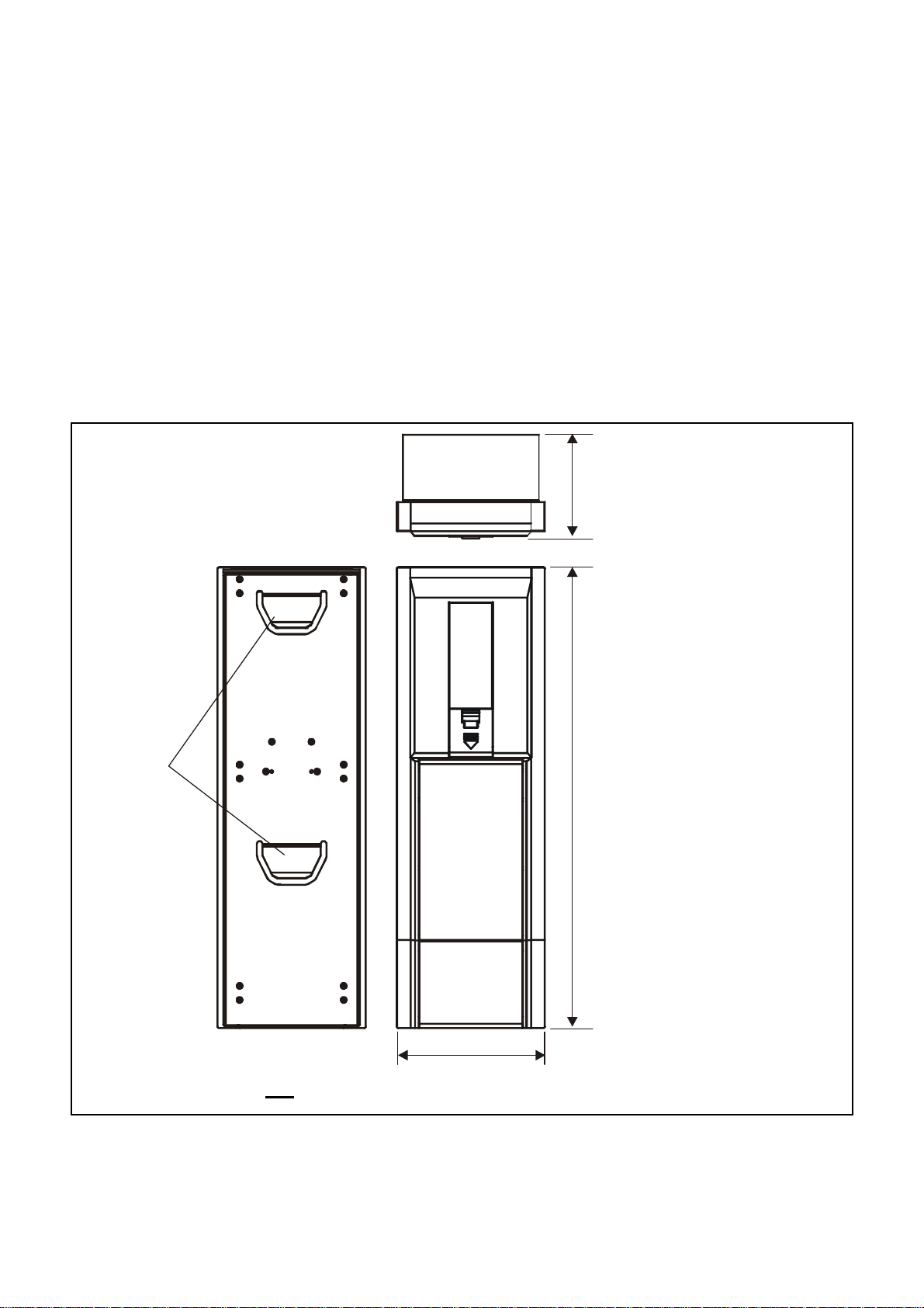
Dimensions
Enclosure
90 mm
(3.5”)
Mounting
Hooks
Note Diagram not to scale.
395 mm
(15.6”)
130 mm
(5.1”)
TP1MAN Issue 3 Apr 06 (MAN0630) 10
Installation
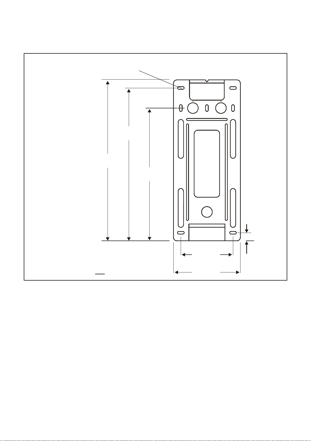
Mounting
Bracket
Mounting Hole (6 off)
228.0 mm
(9.0”)
240.0 mm
(9.5”)
198.0 mm
(7.8”)
Thickness - 5.25 mm (0.2”) max.
12.0 mm
(0.5”)
Note Diagram not to scale.
78.0 mm
(3.0”)
100.0 mm
(3.9”)
Mounting
Touchpoint 1
hooked onto the bracket. The previous diagrams show dimensions for
Fit the bracket to a flat, firm surface, e.g. wall, suitable for the controller’s size and weight.
Recommended screw for mounting is M3.5 x 25 (or #8 x 1").
1 Mark out and drill 4 x M3 holes for the mounting bracket fixing screws.
Use the mounting bracket as a template for the position of the holes.
2 Fix the bracket securely to the wall.
Use appropriate fixings for the surface to which the bracket/controller is mounted.
3 With the bracket secure, locate and then lower Touchpoint 1 onto it.
Ensure both top and bottom hooks on the back of the unit engage properly in the mounting
bracket slots.
is supplied with a mounting bracket that fits onto a suitable wall. The controller is then
Touchpoint 1
and the bracket.
TP1MAN Issue 3 Apr 06 (MAN0630) 11
Installation
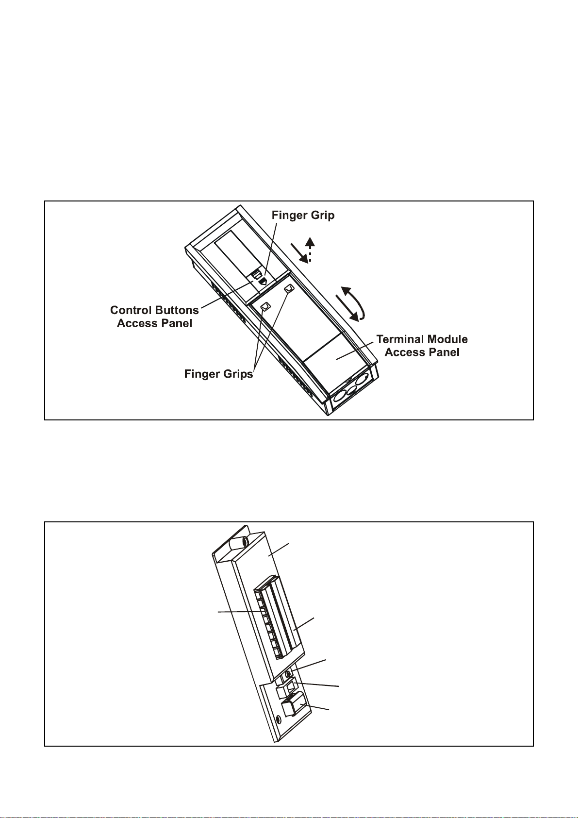
Controller Components
This procedure describes how to access the components inside the controller.
1 Loosen the single captive screw securing the Terminal Module access panel.
The panel is located at the bottom of the enclosure.
2 Push down on the finger grips at the top of the access panel.
3 Slide the panel down to release it.
4 Pull the panel outward.
Pull it until the door is approximately at a right-angle to the enclosure.
5 Push the panel inward toward the enclosure.
This locks it in the open position and provides two handed access to the cable entries, etc.
Terminal Module
16-wire Terminal
Block
z
Terminal Plastic Cover
On/Off Switch
Fuse
3-wire Terminal Block
TP1MAN Issue 3 Apr 06 (MAN0630) 12

Installation
To access the connections on the terminal blocks, slide the plastic cover fitted over
them off.
Ensure the plastic terminal covers are fitted once wiring is complete.
6 After carrying out the procedures subsequently described close and secure the
Terminal Module Access Panel.
Caution Always ensure the cover is replaced/refitted after work is complete.
Power
Touchpoint 1 has an auto sensing power supply capable of operating between 85 and 265 V ac,
50/60 Hz mains supply, and/or 19 to 32 Vdc.
Honeywell Analytics recommend that the power to the controller is sourced from a locally fused
circuit. This should have an isolation facility for maintenance purposes. The table on page 17 and
the terminal block diagram following it show the wiring for power to Touchpoint 1.
Maximum power requirement for worst case detector and relays activated is 30 Wac and/or
15Wdc.
Touchpoint 1 can accept signals from three types of detector. The table summarizes the types
of detector compatible with the controller and the maximum power required.
Type of detector Maximum Power Recommended Detector
2-wire 4-20 mA sink 500 mA (18 to 32 Vdc) Sensepoint Toxic and Oxygen
3-wire 4-20 mA source 500 mA (18 to 32 Vdc) Sensepoint Plus and Sensepoint Pro
3-wire mV bridge 2.9-3.5 Vdc, 200 mA, 0.7 W
Sensepoint Flammable
(max)
Cabling
Touchpoint1 is designed for use in safe areas. Electrical installation should follow national
guidelines using suitably approved cable and glands (M20 or 3/4"NPT) or conduit (3/4"NPT).
Approved cable glands must accommodate a 360 degree termination of the EMI shield.
Screened 0.5mm² (20AWG) to 2.5mm² (14AWG) cross sectional area cable should be used
where appropriate to minimize unwanted effects from RF sources. 1.0mm² (16AWG) is
preferred. Solid or stranded cable may be used. Ensure the cable gland is installed correctly and
fully tightened. The enclosure has three knockouts in the base sized for both M20 and 3/4 in.
NPT fittings.
When running cabling to the unit consider conduit/cable weights to avoid any stress to the unit.
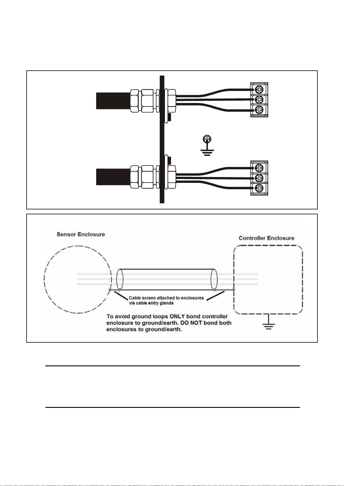
The subsequent diagrams show examples of how to earth-bond Steel Wired Armored (SWA)
cable at enclosures. The same principles apply to conduit installations. These bonding
techniques provide good RFI/EMC performance.
TP1MAN Issue 3 Apr 06 (MAN0630) 13
Installation
To calculate the maximum cable run length from the controller to the detector see page 23.
Neutral
AC Supply
Gas Detector
Live
Earth
Star Ground/Earth Point
+ve
Signal
-ve
Wiring
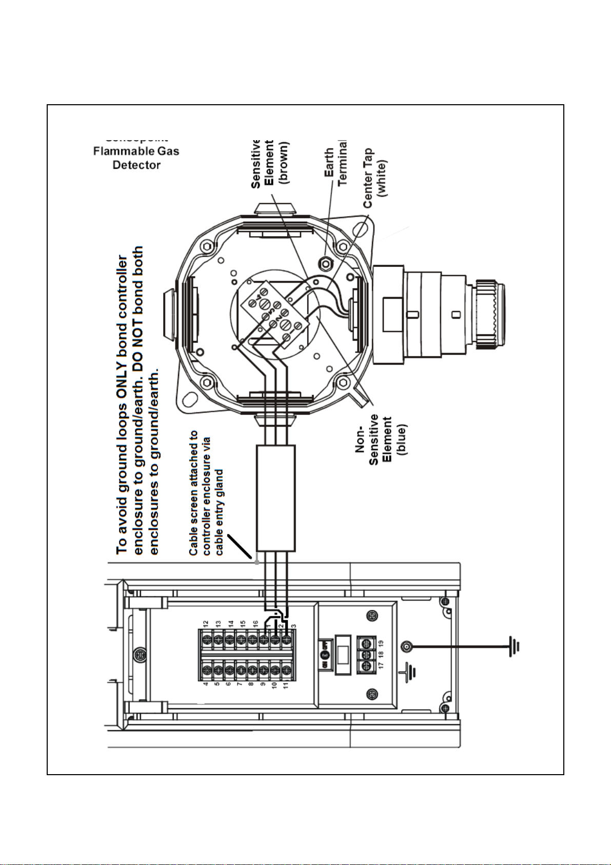
Caution An earth point is provided inside the controller. Ensu re that all
detector screens/armor are grounded at a single earth star point at
the controller or detector — BUT NOT BOTH — to prevent false
alarms due to earth loops.
All electrical wiring connections are made via the Terminal Module. Wire size from 0.5 to
2.5 mm2 (20 AWG to 14 AWG). 1.0 mm2 is preferred.
TP1MAN Issue 3 Apr 06 (MAN0630) 14
Installation
A
B
Always use suitable wiring techniques and crimps when terminating cable cores, especially if
running two cores to a single terminal.
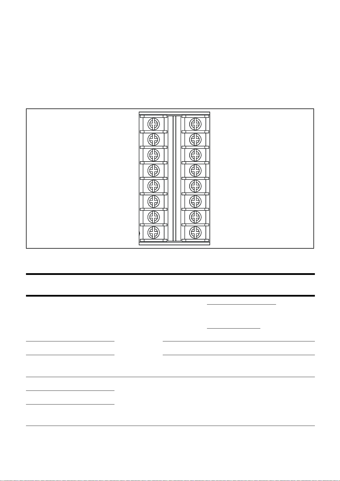
Signal and DC power connections are made via a 16-wire terminal block. Mains power is
connected via a separate 3-wire terminal block.
The diagram shows the 16-wire terminal block layout with terminal identifiers.
11NO
21C
3 1N/C
4FNO
5FC
6FNC
10
7DC+
11
8DC–
4
5
6
7
8
9
12
2NO
13
2C
14
2NC
15
I+
16
I–
1
+
2
S
3
--
This table lists the terminals and their functions and specifications.
Id. Name Function
Input/
Output
Specification
4-20 mA input module:
2-wire, 4-20 mA loop powered, or,
1 Power supply +
Gas detector
connections
2 Signal S Input Variable signal
Output
3-wire, 4-20 mA source
mV input module:
3-wire, mV bridge
3 Power supply - Output 0 Vdc
4 N/O Contact 1NO
Alarm Relay 1 Outputs 240 Vac, 3 A max.5 Common 1C
6 N/C Contact 1NC
TP1MAN Issue 3 Apr 06 (MAN0630) 15
Installation
Id. Name Function
7 N/O Contact FNO
Fault Relay Outputs 240 Vac, 3 A max.8 Common FC
9 N/C Contact FNC
10
DC Power
11 DC–
DC+ DC supply/
battery back-
up
12 N/O Contact 2NO
Alarm Relay 2 Outputs 240 Vac, 3 A max.13 Common 2C
14 N/C Contact 2NC
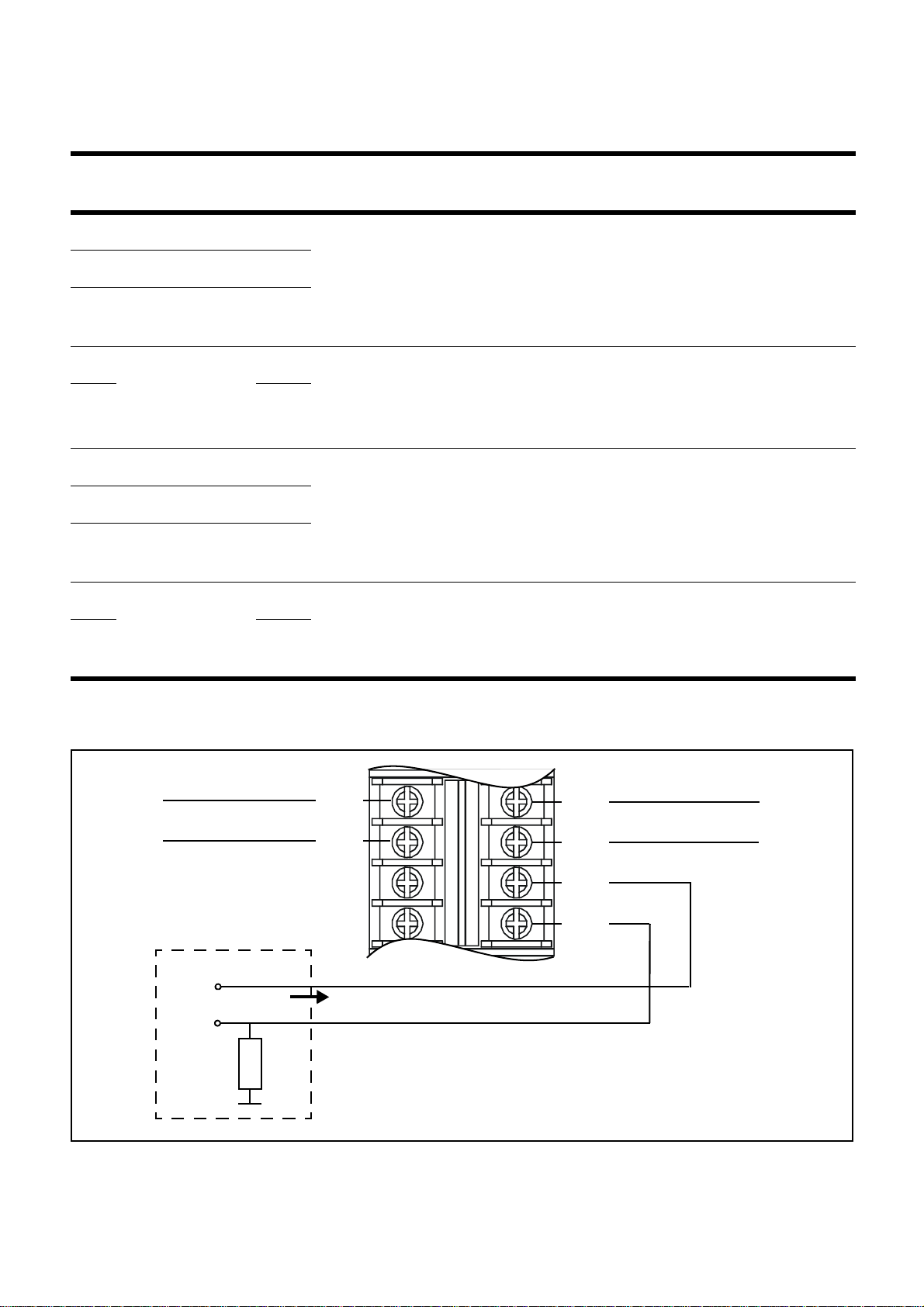
15
* Signal current
output
16 I–
I+
Repeated 4-
20 mA signal
Input/
Output
Specification
Inputs 18 to 32 Vdc
Output 0~22 mA
* The repeated signal output requires an external power supply connected as in the following
diagram.
13
2C
2NC
14
2NC
2C
I+
15
2NO
I-
16
I-
B
4-20 mA
1NO
1NC
1C
1C
1NC
1NO
FNO
I+
A
5
6
7
8
18-20 Vdc
R
TP1MAN Issue 3 Apr 06 (MAN0630) 16
Installation
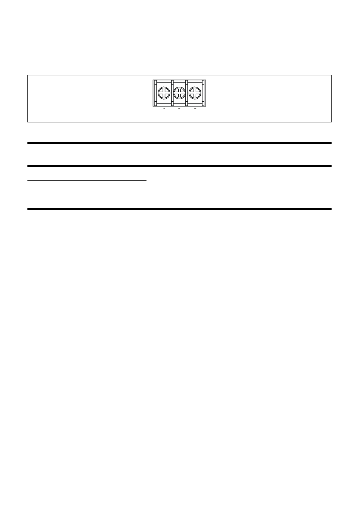
The following diagram shows the 3-wire mains terminal block layout with terminal identifiers.
123
17 18 19
LNE
This table lists the power supply terminals and their functions and specification.
Id. Name Function Input/
Specification
Output
17 Live L
18 Neutral N
19 Earth/Ground E
Power Supply Inputs
85 to 265 Vac,
50/60 Hz, 30 Wac
and/or 15Wdc
max. power
Zareba Sensepoint Gas Detector Connections
Touchpoint 1 is specifically designed for use with the Sensepoint range of gas detectors. The
subsequent diagrams show connection details for these units.
For further information about Sensepoint detectors refer to their individual technical manuals/
data sheets.
TP1MAN Issue 3 Apr 06 (MAN0630) 17
Installation
TP1MAN Issue 3 Apr 06 (MAN0630) 18
 Loading...