

Page 1
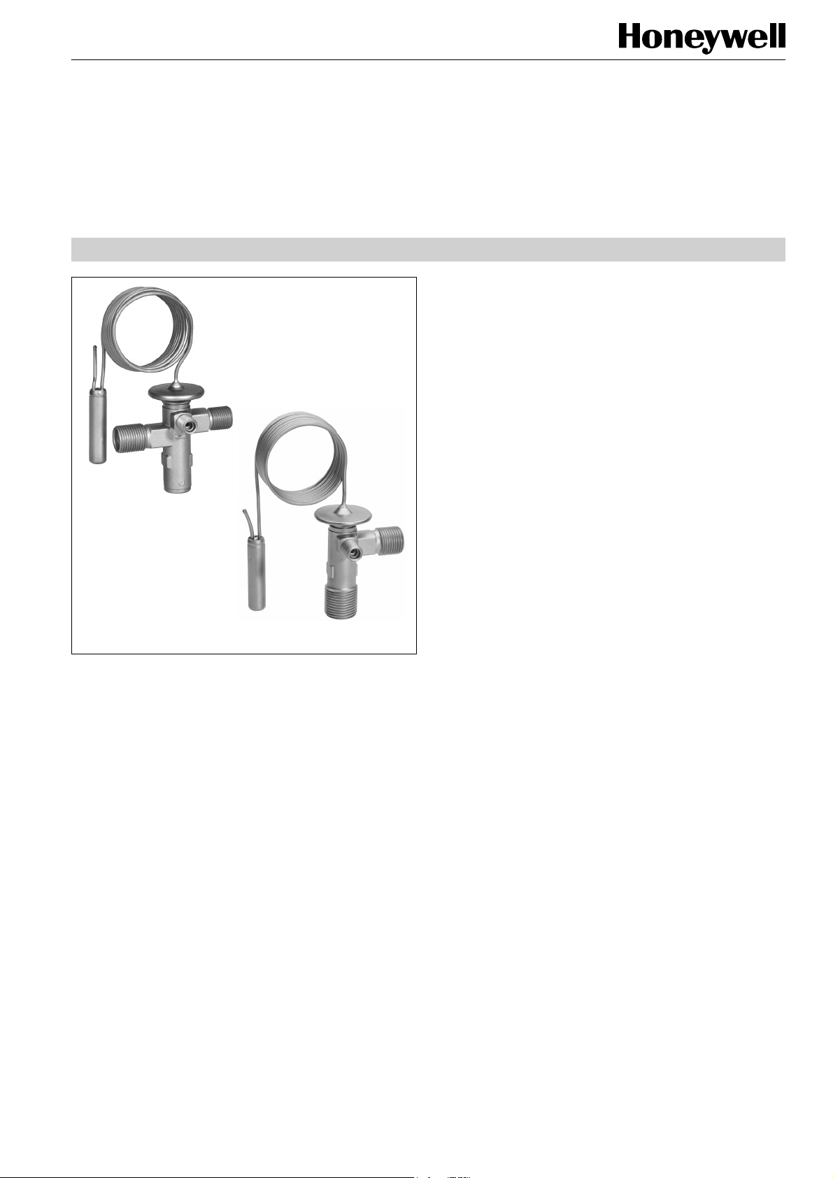
FIXED ORIFICE, O-RING CONNECTIONS
TOEX 0.5 - 4.5 two-way
TOEX 0.5 - 4.5 angle
Application
Thermostatic expansion valves series TOE(X) are used in
plants with one or more refrigerant circuits, especially for
series installations, mobile air-conditioning and cooling units
with O-ring connection, e. g. bus AC, train AC, transport
cooling.
Materials
Body
Thermal head
Connections
brass
stainless steel
brass
Series TOE
THERMOSTATIC EXPANSION VALVES
PRODUCT DATA
Features
• TOE: with internal pressure equalisation; for single
injection in installations with one or more cooling
circuits.
• TOEX: with external pressure equalisation; for optimal
evaporation effectiveness in all applications.
Obligatory for multiple injection by liquid distributors.
• Combi adsorber charge as standard
The same valve can be used for different
refrigerants (see table on page 2)
Controller charge is high sensitive and responsive
thus lowest possible level of superheat can be
achieved
Charge is not sensitive to effects of temperature on
the capillary tube and valve head
damping characteristic results in stable control
behaviour
• Optional available with gas charge and MOP
• Adjustable superheat for two-way construction
• Fixed superheat setting for angle construction
• Warm thermal head provides best reliability
• O-ring connections
• Extreme durable due to stainless steel head and
stainless steel diaphragm welded using protective gas
• Fixed orifice
• Refrigerants: R134a
R22, R407C, R422D
R404A, R507A
Further refrigerants on request.
Specification
Nominal capacity range
Evaporating temperature
range
Maximum pressure PS
Maximum test pressure PF
Max. ambient temperature
Max. bulb temperature
Static superheat
Length of capillary tube
Bulb diameter
0.99 to 17.0 kW R22
(small orifice graduation for
optimal control behaviour)
see table on page 2
see table on page 2
see table on page 2
100 °C
140 °C
approx. 3 K
1.5 m
12 mm
Copyright © 2009 Honeywell GmbH • Subject to change without notice EN0H-1907GE23 R0709
Page 2
SERIES TOE
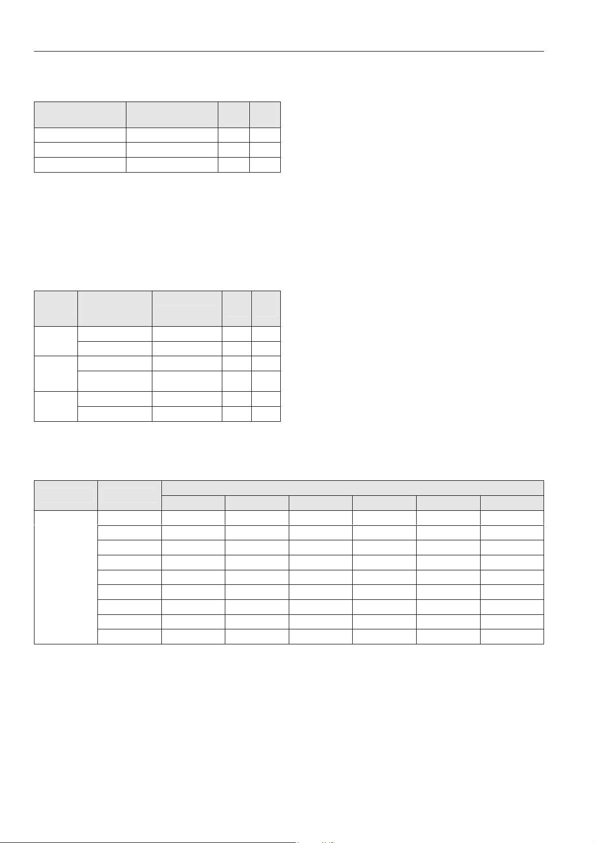
Thermal Charges and Temperature Ranges
1. Adsorber charge
Refrigerant
R134a +15 °C to -30 °C 34 37.4
R22, R407C, R422D +15 °C to -30 °C 36 39.6
R404A, R507A ±0 °C to -30 °C 36 39.6
Further refrigerants on request.
Thermal systems with adsorber charge are completely
insensitive to effects of temperature on the capillary tube and
valve head. It reacts only according to the temperature of the
bulb.
Thus, Honeywell TOE(X) valves with combi adsorber charge
work absolutely reliable, even in icy condition or while
defrosting using hot gas.
2. Adsorber charge with pressure limiting performance (MOP)
Refrigerant
R22,
R407C,
R422D
R404A,
R507A
Further refrigerants and MOP on request
Evaporation
temperature
range
+5 °C to -30 °C MOP A +15 °C 34 37.4 R134a,
-10 °C to -30 °C MOP A ±0 °C 29 31.9
+5 °C to -30 °C MOP A +15 °C 36 39.6
-10 °C to -30 °C MOP A ±0 °C 29 31.9
-10 °C to -30 °C MOP A ±0 °C 36 39.6
-20 °C to -30 °C MOP A -10 °C 34 37.4
Evaporation
temperature range
MOP PS
PS
(bar(a))
(bar(a))
PF
(bar(a))
PF
(bar(a))
3. Gas charge
Refrigerants and MOP on request.
With gas charged valves and MOP it is under all operating
conditions necessary that the bulb is always colder than the
capillary tube and the thermal head!
With the Honeywell TOE series the thermal head is heated
advantageously by the liquid refrigerant. The warm thermal
head is on the safe side at any time.
Capacities
Type Orifice size
0.5 0.69 0.99 0.95 0.67 0.68 0.69
0.7 1.0 1.4 1.3 0.92 0.97 0.98
1.0 1.4 2.0 1.9 1.3 1.4 1.4
TOE
TOEX
* Capacities are based on t0 = +4 °C, tc = +38 °C and 1 K subcooled liquid refrigerant entering the valve.
For other operating conditions see capacity charts in Honeywell catalogue or consult the Honeywell software.
1.5 2.2 3.2 3.1 2.2 2.2 2.3
2.0 2.9 4.0 3.9 2.7 2.8 2.9
2.5 4.0 5.8 5.6 3.9 4.1 4.1
3.0 6.6 9.3 8.9 6.3 6.5 6.6
3.5 8.7 12.2 11.7 8.3 8.6 8.7
4.5 11.8 17.0 16.4 11.3 12.0 12.1
R134a R22 R407C R422D R404A R507A
Nominal capacity (kW)*
EN0H-1907GE23 R0709 2 Honeywell GmbH • Subject to change without notice
Page 3

Dimensions and Weights
SERIES TOE
Type
Two-way
construction
Angle
construction
Connection = size of UNF thread
Inlet
(A)
5/8" UNF 3/4" UNF 7/16" UNF 47.5 40 51.5 38 43 29 approx. 0.34
3/4" UNF 7/8" UNF 7/16" UNF 42.5 - 46.5 40 - 29 approx. 0.34
Connections Dimensions (mm)
Outlet
(B)
Pressure
equalisation (C)
D E F G H I
Weight
(kg)
TOE(X) 0.5 - 4.5 two-way TOE(X) 0.5 - 4.5 angle
Type Code / Order Information
TOE X 4.5 R134a MOP A +15 °C 5/8“ x 3/4“ D
Series
Pressure equalisation:
X = external
() = internal
Orifice size
Refrigerant
Charge type, MOP,
evaporation temperature range
O-ring connection UNF
(inlet x outlet)
D = two-way construction
W = angle construction
Honeywell GmbH • Subject to change without notice 3 EN0H-1907GE23 R0709
Page 4

SERIES TOE
)
Installation
• The valves may be installed in any position.
• The external pressure equaliser line (TOEX) should be
6 mm or 1/4" in diameter and is to be connected downstream of the remote bulb. An overbow is recommended in
order to prevent the ingress of oil into the equaliser line.
• The bulb should preferably be positioned on the upper half
of a horizontal suction line but never after a liquid trap. As
a general rule, bulbs of expansion valves should be
insulated to prevent them being affected by the ambient
temperature.
• When tightening flare nuts of the flare connections grip at
wrench flats on the valve body.
• Do not bend or squeeze the bulb when tightening the bulb
clamp!
• Constructive modifications at the valve are not allowed.
Information for original equipment manufacturers:
The valve series TOE can be customised to the
requirements of your series device in an optimum way.
Contact us!
Superheat Adjustment (Two-way Valve
In general the Honeywell valves should be installed with the
factory setting for the used refrigerant unaltered.
This superheat adjustment is calibrated for lowest
superheating and optimum evaporator utilisation. However,
should it be necessary to adjust the superheat, turn the
adjusting spindle as follows:
Turning clockwise
Turning
counterclockwise
One turn of adjusting spindle alters superheat setting by
approx. 0.25 bar. Increase of superheat setting results in a
lower MOP-value and vice versa.
With TOEX angle construction there is no superheat
setting in built-in condition possible, use factory setting.
reduced refrigerant mass flow,
=
increase of superheat
increased refrigerant mass
=
flow, decrease of superheat
Automation and Control Solutions
Honeywell GmbH
Hardhofweg
74821 Mosbach/Germany
Phone: +49 (0)
Fax: +49 (0)
E-Mail: cooling.mosbach@honeywell.com
KAT-TOE-002
www.honeywell-cooling.com
EN0H-1907GE23 R0709 4 Honeywell GmbH • Subject to change without notice
62 61 / 81-475
62 61 / 81-461
Manufactured for and on behalf of the
Environment and Combustion Controls
Division of Honeywell Technologies Sàrl,
1180 Rolle, Z. A. La Pièce 16, Switzerland
by its authorized representative Honeywell GmbH
 Loading...