

Page 1
TO 485, TO 487 P
Einbau-Anleitung
Installation Instructions
EB-TO485/TO487P=A
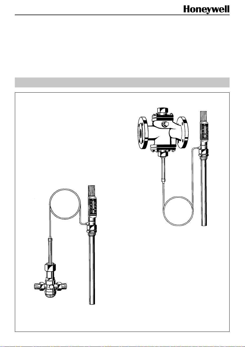
TO 485
TO 487 P
Temperaturregler
Temperature Controls
Page 2
D
1. Einbau
Rohrleitung gründlich säubern. Bei ständigem
Schmutzanfall muss ein Schmutzfänger (FY 69,
FY 71) vorgebaut werden. Stellglied in Durchflussrichtung in die waagrecht verlegte Rohrleitung mit
dem V entilhals nach unten einbauen.
T auchhülse mit Doppelnippel R 11/4" dicht und so in
den Warmwasserbereiter, Gegenstromapparat oder
Rohrleitung einschrauben, dass später die gesamte Fühlerschaft-Länge vom Durchflussmedium
umspült wird.
Thermostat mit Wärmeleitblech in Tauchhülse
einsetzen und mit Überwurfmutter anschrauben.
Bei einer evtl. notwendigen Überholung kann der
Thermostat ohne Entleerung der Anlage ausgebaut
werden.
Kapillarrohr vorsichtig abrollen und Steuerkörper
mit Überwurfmutter und Dichtung an den V entilhals
fest anschrauben. Kapillarrohr vor mechanischen
Beschädigungen schützen und so verlegen, dass
ein Biegeradius von 50 - 60 mm nicht unterschritten wird; nicht knicken!
3. Verwendungsber eich
TO 485
Wasser , ölfreie Pressluft und Stic kstoff bis 70 °C
Betriebsdruck max. 16 bar
Für Drücke über 13 bar ist eine Thermostatentlastung T 447 erforderlich.
R
max. ∆p
bar 444444
kvs-Wert 2,4 3,1 7,6 9,1 12,6 12,6
1
/2"3/4"1"11/4"11/2"2"
TO 487 P
Wasser und Dampf bis max. 16 bar/120 °C oder
Für Drücke über 13 bar ist eine Thermostat-
entlastung T 447 erforderlich.
DN 15 20 25 32 40 50 65
max. ∆p
bar 4444444
kvs-Wert 2 3 7 11 18 28 47
13 bar/150 °C
1
2
5
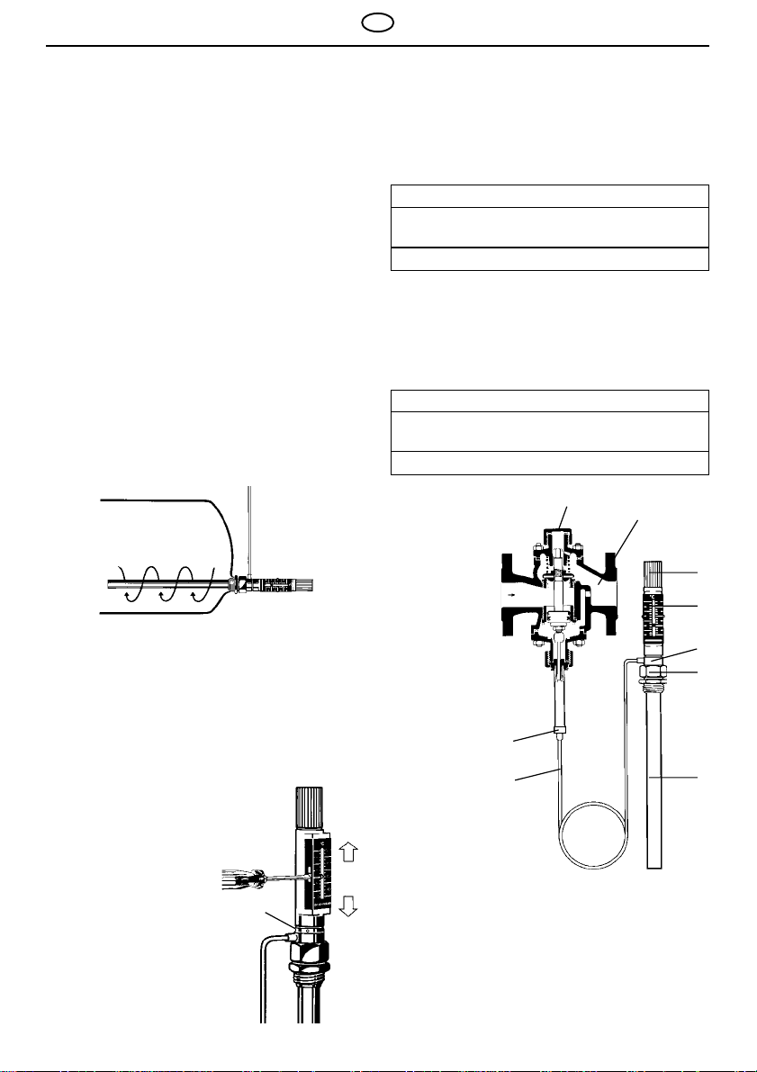
2. Nachjustieren
V or der ersten Inbetriebnahme der Anlage
gewünschte Temperatur an der Sollwerteinstellung
nach Skala einstellen. Die Skala kann nach Lösen
des Konterringes ins Blickfeld gedreht werden.
Konterring wieder fest
anziehen. Bei Inbetriebnahme der Anlage an
Hand des
Kontrollthermometers die
T emperatur mit dem
Sollwert am Thermostat
vergleichen. Die Temperatur des Mediums muss
hiermit übereinstimmen.
Eine evtl. erforderliche
Korrektur kann durch
Lösen der Schrauben und
V erschieben der Skala
vorgenommen werden.
Konterring
3
4
1 Entlüftungsstopfen
2 Stellglied
3 Steuerkörper
4 Kapillarrohr
5 Handrad für Sollwertverstellung
rechts drehen - höhere Temperatur
links drehen - niedrigere T emperatur
6 Konterring
7 Überwurfmutter
8 Sollwertanzeige mit T emperaturskala
9 T auchhülse
2
8
6
7
9
Page 3

GB
1. Installation
Thoroughly flush pipework before installing valve.
If there is a constant dirt problem, then a strainer
(e.g. FY 69, FY 71) should be installed before the
valve. Install in horizontal pipework with flow in
direction of arrow with the regulating unit pointing
downwards.
Screw immersion pocket with double R11/4” nipple
tightly into the boiler, contraflow de vice or
pipework, so that the medium will flow around the
whole length of the immersion pocket.
Fit the thermostat in the pocket with the heat
diffuser plate and tighten with the backnut.
The thermostat can be removed and exchanged
without draining the installation.
Unwind the capillary tube carefully and fix tightly
into the control body with backnut and seal.
Protect the capillary tube against mechanical
damage and install it in such a way that the
bending radius is not less than 50 - 60mm. It is
important that the tube must not be kniked.
3. Range of applications
TO 485
Water, oil free compressed air and nitrogen
up to 70 °C.
Operating pressure maximum 16.0 bar.
A thermostat relief T 447 is required for
pressures above 13.0 bar .
R
max. ∆p
bar 444444
kvs-value 2,4 3,1 7,6 9,1 12,6 12,6
1
/2"3/4"1"11/4"11/2"2"
TO 487 P
Water and steam up to max.16 bar/120 °C
A thermostat relief T 447 is required for
pressures above 13.0 bar .
DN15 20 25 32 40 50 65
max. ∆p
bar 4444444
kvs-value 2 3 7 11 18 28 47
13 bar/150 °C
1
2
5
2. Adjustment
Before putting the installation into operation, set
the temperature to the required value on the scale.
The scale can be turned to be visible by loosening
the locking ring. Retighten the locking ring. On
starting operation of the
system, compare
temperature with the set
temperature on the
thermostat using a
thermometer. The
temperature of the
medium must correspond
with the set temperature.
Any necessary
adjustment is then
possible by loosening the
screws and moving the
scale.
Locking
ring
3
4
1 Venting plug
2 Body
3 Control body
4 Capillary tube
5 Hand wheel for set temperature adjustment
- turn clockwise for higher temperature
- turn anti-clockwise for lower temperature
6 Locking ring
7 Backnut
8 Temperature setting indicator with
temperature scale
9 Imersion pocket
3
8
6
7
9
Page 4

D GB
4. Einbaubeispiel
TO 487 P als Kühlwassertemperaturregler
TO 487 P as a temperature control for cooling water
.
Installation Example
Honeywell AG www.honeywell.de/haustechnik
Hardhofweg . D-74821 Mosbach http://europe.hbc.honeywell.com
MU1H-1320GE23R1201
 Loading...