

Page 1
Construction
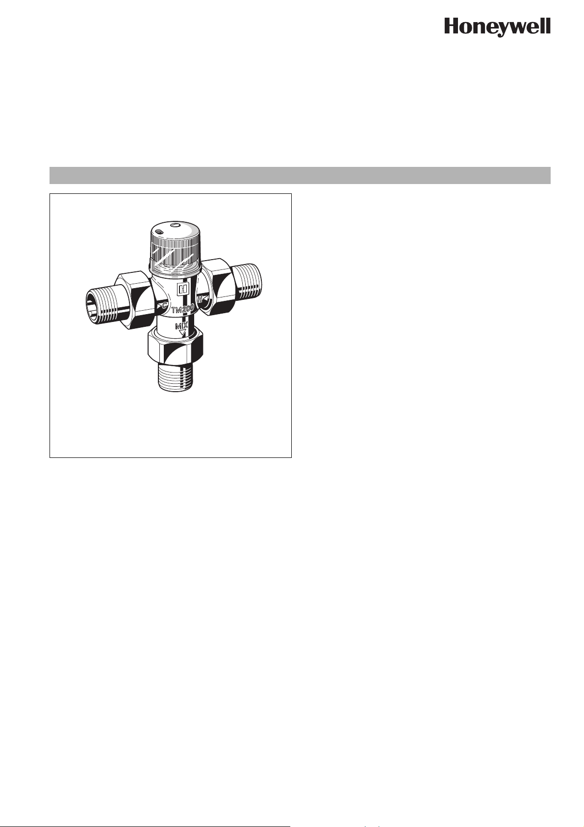
The thermostatic mixing valve comprises:
•Housing
• Threaded or soldered union connectors
•Adjuster knob
• Protective cap for locking the set mixed temperature
•Thermostat
Materials
• Dezincification resistant brass housing
• Brass threaded connections
• Moving parts of high-quality, scale-resistant synthetic
material
• Transparent plastics protective cap
• Plastics adjuster knob
• NBR seals
• Stainless steel spring
EN0H-1306GE23 R0807 • Subject to change
TM200
Thermostatic mixing valve
with scald protection
Product specification sheet
Application
Thermostatic mixing valves of this type provide control of the
water temperature and are used:
• For centralised control on hot water supply units or for localised control adjacent to point-use outlets
• In heating systems with underfloor heating or for limiting boiler
return temperatures
Where a system includes a hot water circulation circuit, a KB 191
return flow retarder unit (see accessories) must be fitted to
prevent cold water backfeeding and cooling the mixed water at
the outlets.
Special Features
• Highly sensitive thermal element with good all-round watertemperature sensing, even at low flow rates
• Simple setting of the required water temperature
• Scald protection - the hot water inlet is automatically cut off if
the cold supply fails provided that the hot water inlet temperature is at least 10 K higher than that of mixed water setting
• The cold water inlet is automatically cut off if the hot supply
fails
• Meets KTW recommendations for potable water
• Inner components are of scale-resistant materials
Range of Application
Medium Water
Operating pressure Max. 10 bar
Maximum pressure difference between hot and
cold inlet supplies
Technical Data
Installation position As required
Hot water inlet temperature
Connection size R
Setting range 30 °C - 60 °C
Flow rate at 1.0 bar pressure differential across
valve approximately
Control accuracy < ± 4 K
2.5 bar
Max. 90 °C
3
/4" or ∅ 22
Set during manufacture 40 °C
27 l/min
www.honeywell.com 31
Page 2
TM200 Thermostatic mixing valve
Method of Operation
a) As a mixing valve for hot water supply systems and heating
systems:
The highly sensitive thermal element located in the outlet of the
valve controls a plug which regulates the flow proportions of cold
and hot water in relation to the mixed hot water setting selected.
Soft seatings are fitted to both hot and cold water inlets.
They provide:
• A positive hot inlet shutoff if the cold water supply is interrupted, provided that the hot water inlet temperature is at
least 10 K higher than that of the mixed water setting.
• The cold water supply is cut off if the hot water supply is interrupted.
b) As a diverter valve on central heating systems:
For this application flow through the valve is in the reverse direction compared with its use as a hot water mixing valve. The inlet
water passes around the sensing element and regulates the
control piston so that for temperatures above the set value the
water is returned to the heating circuit and for temperatures
lower than the set value the water is diverted to the boiler.
A protective cap is supplied with the valve to lock the mixed
temperature setting.
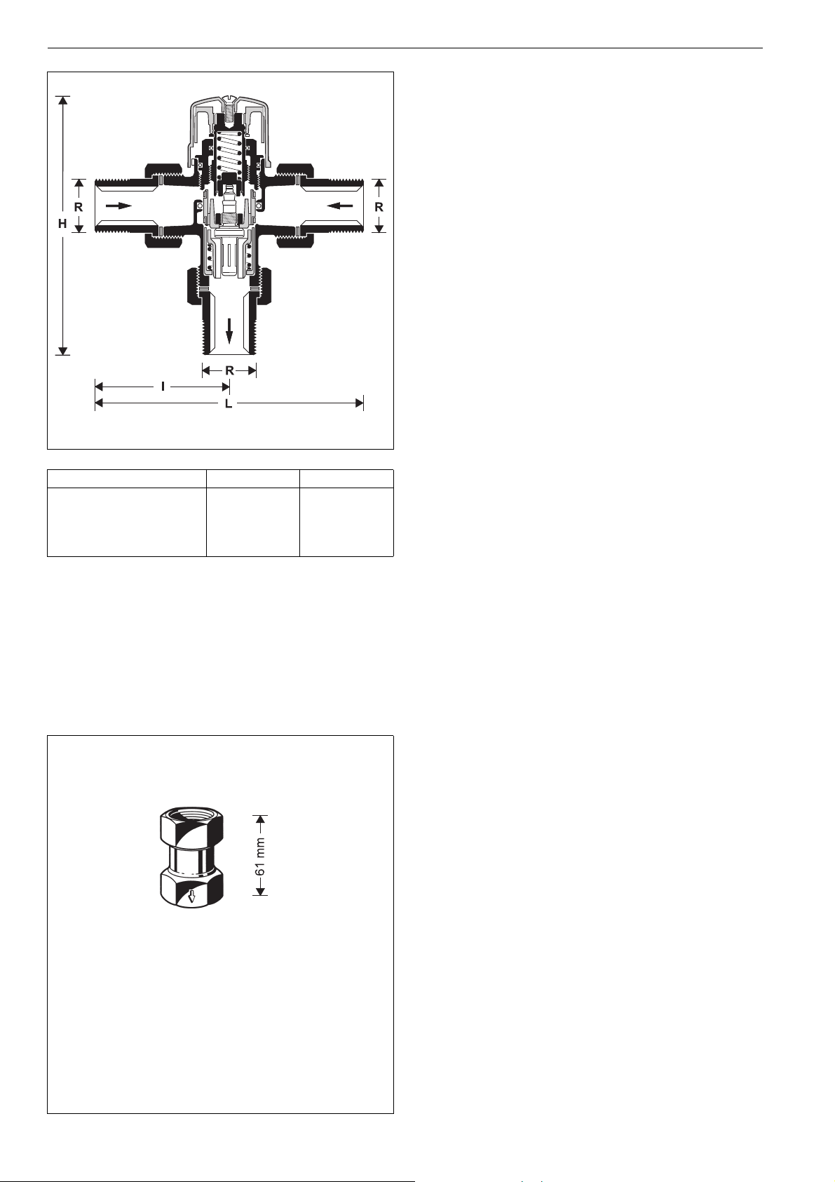
Connection size R
Dimensions (mm)
3
/4" ∅ 22 mm
L
l
H
134
67
128
122
61
122
Options
TM200-3/4A = With R
3
/4" threaded male connections
TM200-3/4B = With ∅ 22 mm soldered connections
Accessories
KB191-3/4 Return flow-retarder unit
for fitting to systems which include a hot water circulation circuit - to prevent cold water backfeeding and
cooling the mixed water at the outlets.
Operating pressure:max. 10 bar
Operating temperature:max. 90 °C
Installation orientation:Arrow pointing in flow
direction
32 www.honeywell.com
KB191
EN0H-1306GE23 R0807 • Subject to change
Page 3

Installation Example
a) Mixing valve in hot water supply systems
1/2" max. 17 m
3/4" max. 10 m
TM200 Thermostatic mixing valve
1/2" max. 17 m
3/4" max. 10 m
RV284
KB191
RV281
10
5
bar
15
0
16
10
5
bar
15
0
16
Central control of water
temperature
Zone control of water temperatur
Central control of water temperature in solar heated, dual-energysource systems
a) Mixing valve in hot water supply systems b) Diverter valve in central heating systems
VT100
VT100
Heating circuit at
Underfloor heating
boiler temperature
Installation Guidelines
• Install so that the valve is not strained or twisted
• Fit a return flow-retarder unit where the hot water supply
system includes a circulation circuit
• Observe the flow direction arrow when fitting a KB191 return
flow-retarder unit
• To prevent the growth of legionella, DVGW-W551 and W552
specify that the water volume in the pipework between the
mixer valve and the furthest take-off point should not exceed
3 litres. This corresponds to a maximum length of 10 metres
3
for
/4" (20 mm) pipework and 17 metres for 1/2" (15 mm)
Typical Applications
Thermostatic mixing valves of this type can be used within the
limits of their specification for the control of hot water supply or
central heating systems.
The following are some typical applications:
a) Hot water supply systems:
o Single and multiple-occupancy households
o Retirement homes
o Children's nurseries
o Schools
oHotels
Limiting of boiler return
temperature
o Commercial kitchens
o For industrial applications with control either from a central
location or adjacent to point-of-use outlets
b) Central heating systems:
o As a mixing valve for underfloor heating systems
o As a diverter valve for limitation of boiler return tempera-
tures
Maintenance
No specific maintenance is necessary under normal operating conditions. However, all moving parts which may be subject to wear
can be exchanged.
EN0H-1306GE23 R0807 • Subject to change
www.honeywell.com 33
Page 4
TM200 Thermostatic mixing valve
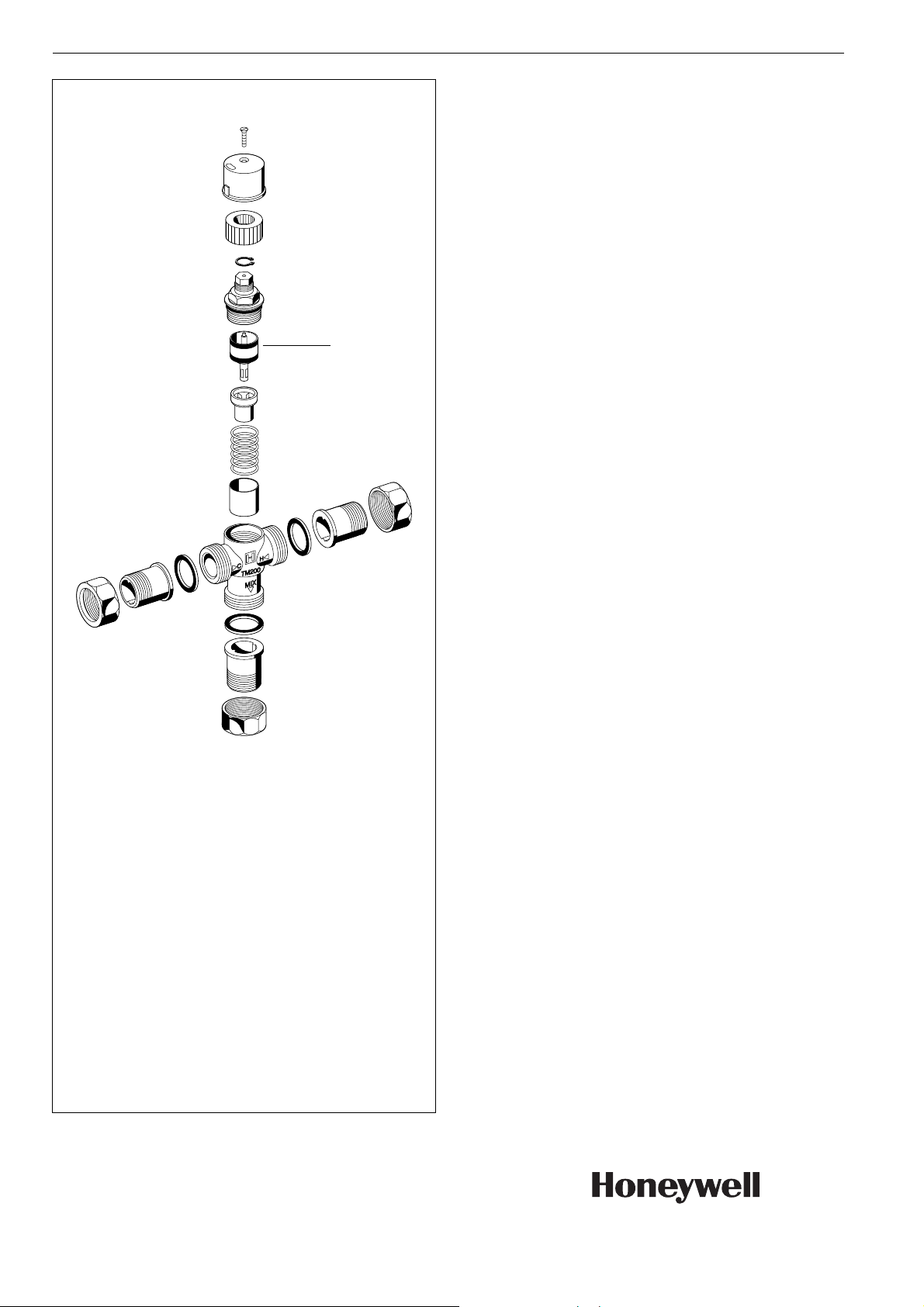
Spare Parts
Thermostatic Mixing Valve TM200, from 1996 onwards
No. Description Dimension Part No.
1 Regulation valve
TM200A-30/60
complete
1
Automation and Control Solutions
Honeywell GmbH
Hardhofweg
D-74821 Mosbach
Phone: (49) 6261 810
Fax: (49) 6261 81309
http://europe.hbc.honeywell.com
www.honeywell.com
Manufactured for and on behalf of the
Environmental and Combustion Controls Division
of Honeywell Technologies Sàrl, Ecublens, Route
du Bois 37, Switzerland by its Authorised Representative Honeywell GmbH
EN0H-1306GE23 R0807
Subject to change without notice
© 2007 Honeywell GmbH
 Loading...