

Page 1
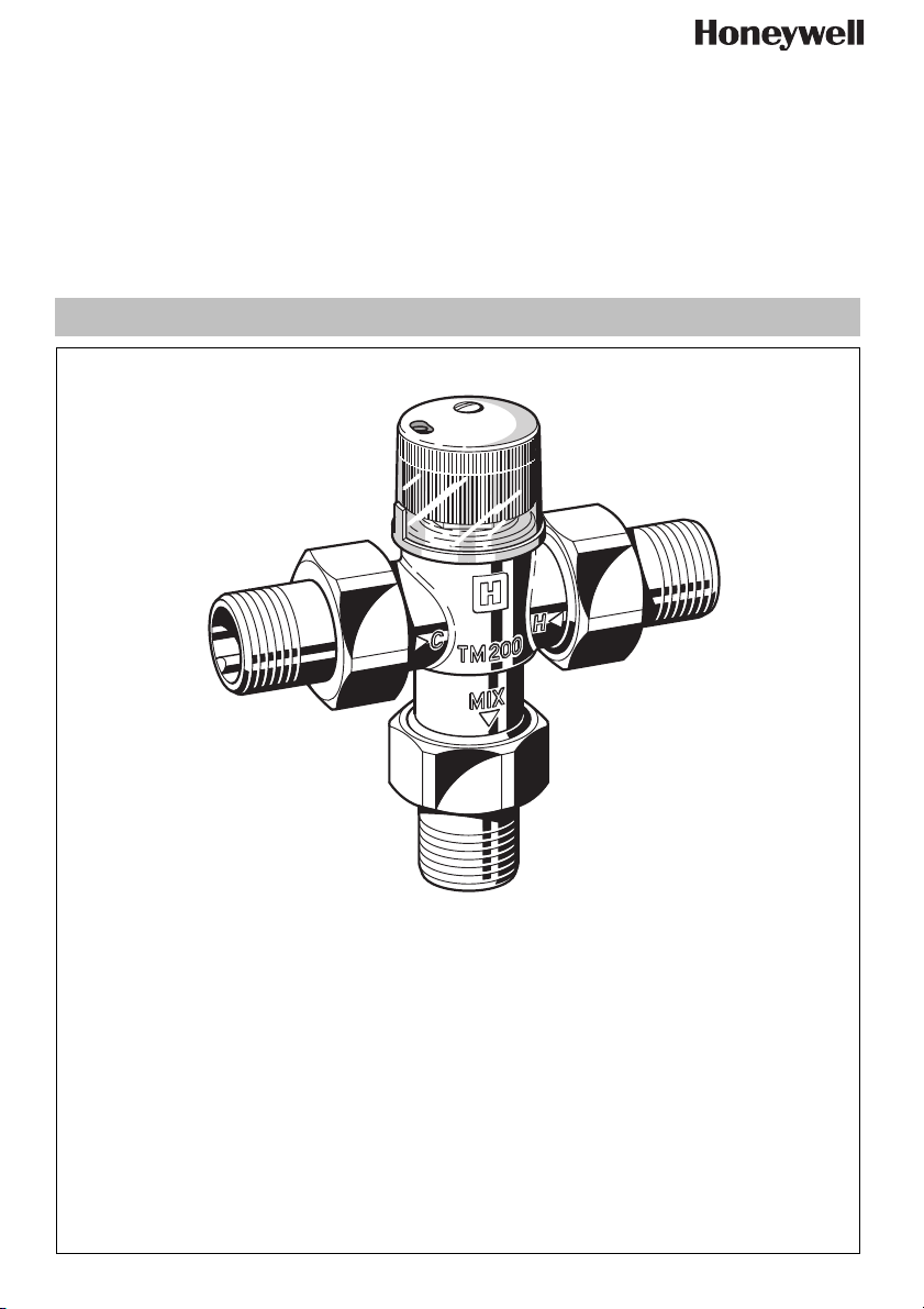
TM200
Einbauanleitung • Installation instruction • Notice de montage
Installatievoorschrift • Istruzioni di montaggio • Asennusohje
Anleitung zum späteren Gebrauch aufbewahren!
Keep instructions for later use!
Conserver la notice pour usage ultérieur!
Handleiding bewaren voor later gebruik!
Conservare le istruzioni per uso successivo!
EB-TM200 Rev. A
Thermostatischer Wassermischer
Thermostatic Mixing Valve
for domestic water
Mitigeur thermostatique
pour eau domestique
Thermostatische mengkraan
Miscelatore termoststico
per acqua servici
Termostaattinen sekoitusventtiili
Page 2

D
1. Sicherheitshinweise
1. Beachten Sie die Einbauanleitung.
2. Benutzen Sie das Gerät
• bestimmungsgemäß
• in einwandfreiem Zustand
• sicherheits- und gefahrenbewusst.
3. Beachten Sie, dass das Gerät ausschließlich für
den in dieser Einbauanleitung genannten Verwendungsbereich bestimmt ist. Eine andere oder
darüber hinausgehende Benutzung gilt als nicht
bestimmungsgemäß.
4. Beachten Sie, dass alle Montage-, Inbetriebnahme,
Wartungs- und Justagearbeiten nur durch autorisierte Fachkräfte ausgeführt werden dürfen.
5. Lassen Sie Störungen, welche die Sicherheit beeinträchtigen können sofort beseitigen.
2. Funktionsbeschreibung
Thermostatische Wassermischer TM 200 dienen zur
Regelung der Wassertemperatur in Warmwasserbereitungsanlagen an zentraler Stelle, dezentral an der
Entnahmestelle, in solarbetriebenen, bivalenten
Warmwasserbereitern oder in Heizungsanlagen bei
Fußbodenheizungen oder zur Begrenzung der Kesselrücklauftemperatur.
a) Mischventil in Warmwasser- und Heizungsanlagen
Der im Ausgangsstutzen zentral angeordnete hochempfindliche Thermostat steuert eine Regulierhülse,
die in Abhängigkeit der Mischwassertemperatur den
Zustrom von Kalt- bzw. Heißwasser regelt. Der Steuerkolben besitzt auf der Kalt- und Heißwasserseite
Weichdichtungen.
Diese bewirken:
• Einen dichten Abschluss auf der Heißwasserseite
bei Ausfall der Kaltwasserversorgung, unter
Voraussetzung, dass die Heißwassertemperatur
min. 10 K höher ist als die eingestellte Mischwassertemperatur.
• Eine Unterbrechung der Kaltwasserzufuhr bei
Ausfall der Heißwasserversorgung
b) Verteilventil in Heizungsanlagen
Das Ventil wird hier im Vergleich zum Mischventil
umgekehrt durchströmt. Das eintretende Wasser
umspült den Thermostat und steuert den Steuerkolben
derart, dass bei Temperaturen größer dem Sollwert
das Wasser zurück in die Heizungsanlage fließt, bei
Temperaturen kleiner dem Sollwert das Wasser zum
Heizkessel geleitet wird.Zur Fixierung der einge-
stellten Mischwassertemperatur wird eine Schutzkappe mitgeliefert.
3. Verwendung
Durchflussmedium Wasser
Betriebsdruck Max. 10 bar
Maximale Druckdifferenz 2,5 bar
4. Technische Daten
Einbaulage Beliebig
Heißwasserzufuhr Max. 90 °C
3
Anschlussgrößen R
/4" oder ∅ 22
Einstellbereich 30 °C - 60 °C
werksseitig eingestellt auf
40 °C
Durchflussmenge
27 l/min
bei ∆p = 1 bar
Regelgenauigkeit < ± 4 K
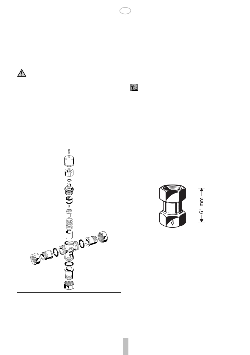
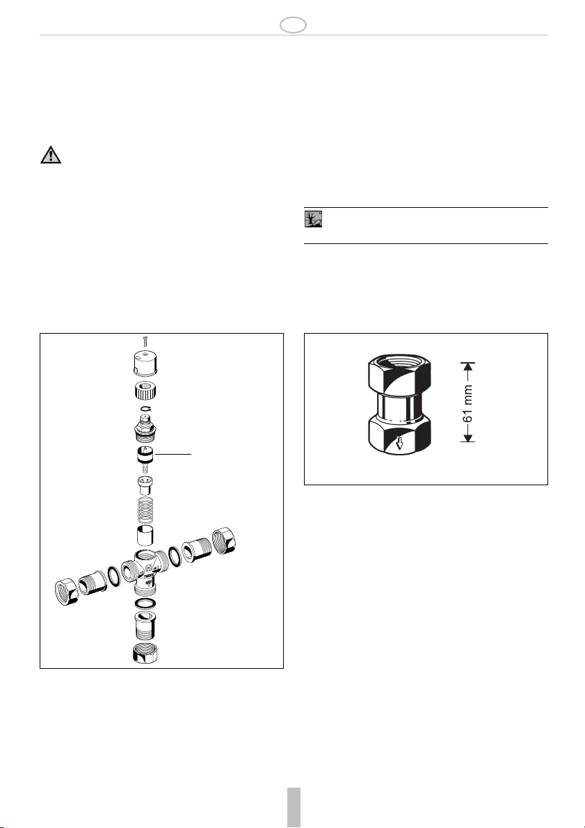
5. Lieferumfang
Der thermostatische Wassermischer besteht aus:
• Gehäuse
• Verschraubungen
• Einstellgriff
• Schutzkappe zum Fixieren der eingestellten Mischwassertemperatur
•Thermostat
6. Varianten
3
TM200-3/4A = mit Gewindetülle R
/4"
TM200-3/4B = mit Löttülle ∅ 22 mm
7. Montage
7.1 Einbauhinweise
• Spannungs- und biegemomentfrei einbauen
• In Zirkulationsleitung von Anlagen zur Warmwasserbereitung eine Kaltwasserbremse einbauen
• Fließrichtung beim Einbau der Kaltwasserbremse
KB191 beachten
• Zur Vermeidung des Legionellenwachstums soll
nach DVGW-W551 und W552 das Wasservolumen
in der Rohrleitung zwischen Mischarmatur und
entferntester Entnahmestelle nicht größer als 3 Liter
sein. Dies bedeutet eine max. Leitungslänge von
3
10 m bei
/4" (20 mm) und 17 m bei 1/2" (15 mm)
MU1H-1306GE23 R0107 2 Honeywell GmbH
Page 3
D
7.2 Montageanleitung
7.2.1 Als Mischventil:
Beim Anschluß an die Warm- und Kaltwasserleitung
muß die Durchflußrichtung mit den Pfeilen auf dem
Gehäuse übereinstimmen.
7.2.2 Als Verteilerventil:
Das Ventil wird hier im Vergleich zum Mischventil umgekehrt durchströmt. Durchströmung
entgegen den Pfeilen auf dem Gehäuse.
7.2.3 Ventileinstellung ändern
Die Mischwassertemperatur kann im Bereich von
30 °C bis 60 °C eingestellt werden.
• Schutzkappe abnehmen. Um die Temperatur zu
verändern
• Einstellrad drehen bis die gewünschte Temperaturkennzahl mit der Markierung 8 übereinstimmt.
9. Ersatzteile
8. Entsorgung
• Gehäuse aus entzinkungsbeständigem Messing
• Verschraubungen aus Messing
• Gleitteile aus hochwertigem Kunststoff, kalkabweisend
• Schutzkappe aus transparentem Kunststoff
• Einstellgriff aus Kunststoff
• Dichtungen aus NBR
• Federn aus nichtrostendem Stahl
Die örtlichen Vorschriften zur ordnungsgemäßen Abfallverwertung bzw. Beseitigung
beachten!
10. Zubehör
1
KB191
KB191-3/4 Kaltwasserbremse
wird in die Zirkulationsleitung eingebaut
und verhindert, dass an den Zapfstellen
Thermischer Wassermischer TM200, Baureihe ab
1996
1 Regulierventil
komplett
Honeywell GmbH 3 MU1H-1306GE23 R0107
TM200A-30/60
Kaltwasser über die Zirkulationsleitung
beigemischt wird.
Betriebsdruck: max. 10 bar
Temperatur: max. 90 °C
Einbaulage: Pfeil in
Fließrichtung
Page 4

GB
1. Safety Guidelines
1. Follow the installation instructions.
2. Use the appliance
• according to its intended use
• in good condition
• with due regard to safety and risk of danger.
3. Note that the appliance is exclusively for use in the
applications detailed in these installation instructions. Any other use will not be considered to comply
with requirements and would invalidate the warranty.
4. Please take note that any assembly, commissioning, servicing and adjustment work may only be carried out by authorized persons.
5. Immediately rectify any malfunctions which may influence safety.
2. Functional description
TM 200 thermostatic mixing valves provide control of
the water temperature for centralised control on hot
water supply units or for localised control adjacent to
point-of-use outlets. Or for solar-heated hot water units
with dual energy source in heating systems with underfloor heating or for limiting boiler return temperatures.
a) As a mixing valve for hot water supply systems and
heating systems:
The highly sensitive thermal element located in the
outlet of the valve controls a plug which regulates the
flow proportions of cold and hot water in relation to the
mixed hot water setting selected. Soft seatings are fitted to both hot and cold water inlets.
They provide:
• A positive hot inlet shutoff if the cold water supply is
interrupted, provided that the hot water inlet temperature is at least 10 K higher than that of the mixed
water setting.
• The cold water supply is cut off if the hot water supply is interrupted.
b) As a diverter valve on central heating systems:
For this application flow through the valve is in the reverse direction compared with its use as a hot water
mixing valve. The inlet water passes around the sensing element and regulates the control piston so that
for temperatures above the set value the water is returned to the heating circuit and for temperatures lower
than the set value the water is diverted to the boiler.
A protective cap is supplied with the valve to lock the
mixed temperature setting.
3. Application
Medium Water
Operating pressure Max. 10 bar
Maximum pressure difference bet-
2.5 bar
ween hot and cold inlet supplies
4. Technical data
Installation position As required
Hot water inlet temperature Max. 90 °C
Connection size R
3
/4" or ∅ 22
Setting range 30 °C...60 °C
Set during manufacture 40 °C
Flow rate at 1.0 bar pressure diffe-
27 l/min
rential across valve approximately
Control accuracy < ± 4 K
5. Scope of delivery
The thermostatic mixing valve comprises:
• Housing
• Threaded or soldered union connectors
• Adjuster knob
• Protective cap for locking the set mixed temperature
•Thermostat
6. Options
3
TM200-3/4A = With R
/4" threaded male connections
TM200-3/4B = With ∅ 22 mm soldered connections
7. Assembly
7.1 Installations Guidelines
• Install so that the valve is not strained or twisted
• Fit a return flow-retarder unit where the hot water
supply system includes a circulation circuit
• Observe the flow direction arrow when fitting a
KB191 return flow-retarder unit
• To prevent the growth of legionella, DVGW-W551
and W552 specify that the water volume in the pipework between the mixer valve and the furthest takeoff point should not exceed 3 litres. This corre-
3
sponds to a maximum length of 10 metres for
(20 mm) pipework and 17 metres for
1
/4"
/2" (15 mm)
MU1H-1306GE23 R0107 4 Honeywell GmbH
Page 5
GB
7.2 Assembly instructions
7.2.1 As a mixing valve:
The flow direction arrows must be observed when connecting the hot and cold water inlets.
7.2.2 As a diverter valve:
For this application flow is in the reverse direction and therefore is in the opposite direction to
the arrows on the housing.
7.2.3 Changing the setting
The mixing valve can be set within the range 30°C to
60°C as follows:
• Remove the protective cap.
• Turn the adjuster knob until the required setting
number aligns with the index mark 8 on the valve
body.
9. Spare Parts
1
8. Disposal
• Dezincification resistant brass housing
• Brass threaded connections
• Moving parts of high-quality, scale-resistant synthetic
material
• Transparent plastics protective cap
• Plastics adjuster knob
•NBR seals
• Stainless steel spring
Observe the local requirements regarding correct waste recycling/disposal!
10. Accessories
KB191
KB191-3/4 Return flow-retarder unit
for fitting to systems which include a hot
water circulation circuit - to prevent cold
water backfeeding and cooling the mixed
water at the outlets.
Operating pressure: max. 10 bar
Operating temperature: max. 90 °C
Installation orientation: Arrow pointing in
flow direction
Thermostatic mixing TM200, from 1996 onwards
1 Regulation valve
complete
Honeywell GmbH 5 MU1H-1306GE23 R0107
TM200A-30/60
Page 6

F
1. Consignes de sécurité
1. Suivre les indications de la notice de montage.
2. En ce qui concerne l'utilisation de l'appareil
• Utiliser cet appreil conformément aux données
constructeur
• Maintenir l'appareil en parfait état
• Respectez les consignes de sécurité
3. Il faut noter que cet équipement ne peut être mis en
oeuvre que pour les conditions d'utilisation mentionnées dans cette notice. Toute autre utilisation, ou
le non respect des conditions normales d'utilisation,
serait considérée comme non conforme.
4. Observer que tous les travaux de montage, de mise
en service, d'entretien et de réglage ne pourront
être effectués que par des spécialistes autorisés.
5. Prendre des mesures immédiates en cas d'anomalies mettant en cause la sécurité.
2. Description fonctionnelle
Les mitigeurs thermostatiques TM 200 servent à régler
la température de l'eau dans les installations d'eau
chaude sanitaire en position centrale, au point de
captage en position décentralisée ou encore dans les
installations génératrices d'eau chaude bivalentes de
type solaire dans les installations destinées à chauffer
le sol ou pour limiter la température de retour de la
chaudière.
a) Soupape du mitigeur dans les installations d'eau
chaude et froide
Le thermostat très sensible placé au centre de
l'embout de sortie commande un douille de régulation
qui selon la température de l'eau mitigée, régule
l'amenée d'eau chaude ou froide. Le piston de
commande possède des joints souples aussi bien du
côté de l'eau froide que de l'eau chaude.
Ceux-ci ont pour effet :
• Une terminaison étanche du côté de l'eau chaude
en cas de panne de l'alimentation en eau froide,
pour autant que la température de l'eau chaude soit
10 K plus haute que la température de l'eau mitigée
réglée.
• Une interruption de l'amenée d'eau froide en cas de
panne de l'alimentation en eau chaude
b) Soupape de distribution dans les installations de
chauffage
Comparée au mitigeur la vanne laisse passer l'eau en
sens inverse. L'eau entrante rince le thermostat et
commande le piston de commande de sorte que lors
MU1H-1306GE23 R0107 6 Honeywell GmbH
de températures plus hautes que la valeur de consigne
l'eau retourne dans l'installation de chauffage, lors de
températures plus basses que la valeur de consigne
l'eau est dirigée vers la chaudière. Pour fixer la température de l'eau mitigée réglée, un couvercle de protection est livré.
3. Mise en oeuvre
Medium du courant Eau
Pression de service Max. 10 bar
Différence de pression maximale 2,5 bar
4. Caractéristiques
Position de montage quelconque
Amenée d'eau chaude Max. 90 °C
3
Calibres des raccords R
Plage de réglage 30 °C - 60 °C réglé par
Débit du courant à ∆p = 1 bar 27 l/min
Exactitude de réglage < ± 4 K
/4" ou ∅ 22
l'usine à 40°C
5. Contenu de la livraison
Le mitigeur d'eau thermostatique est composé de :
• Corps
•Raccords
• Poignée de réglage
• Couvercle de protection pour fixer la température de
l'eau mitigée réglée
•Thermostat
6. Variantes
TM200-3/4A = Avec gaine filetée R
TM200-3/4B = avec gaine à souder ∅ 22 mm
7. Montage
7.1 Dispositions à prendre
• Montage libre de tension et de couple de flexion
• Dans les conduites de circulation d'installations
pour la préparation d'eau chaude, montez un frein
d'eau froide
• Respectez la direction du courant lors du montage
du frein d'eau froide KB191
• Afin d'éviter le développement de légionelles, le
volume d'eau entre le mélangeur et le point de
prélèvement le plus éloigné d'après DVGW-W551 e
W552, ne pourra pas dépasser les 3 litres. Cela
signifie une longueur de tube maximale de 10 m
pour 3/4" (20 mm) et de 17 m pour 1/2" (15 mm )
Page 7

F
7.2 Instructions de montage
7.2.1 Comme mitigeur:
Lors du raccord à la conduite d'eau chaude et froide le
sens de direction du courant doit correspondre aux
flèches situées sur le boîtier.
7.2.2 Comme vanne distributrice:
Comparée au mitigeur la vanne laisse passer
l'eau en sens inverse. Le sens d'écoulement est
opposé à celui indiqué par les flèches sur le
corps de vanne.
7.2.3 Modification du réglage
La température de l'eau mitigée se règle dans une
plage de 30°C à 60°C.
• Retirez le couvercle de protection afin de pouvoir
modifier la température
• Tournez la roue de réglage jusqu'à ce que le chiffre
de la température requise se trouve en face de la
marque 8.
9. Pièces de rechange
8. Matériel en fin de vie
• Corps en laiton résistant à la dégalvanisation
• Vissages en laiton
• Parties coulissantes en plastique qualitatif, ne laissant pas le calcaire adhérer
• Couvercle de protection en plastique transparent
• Poignée de réglage en plastique
• Joints en NBR
• Ressorts en INOX
Se conformer à la réglementation pour l'élimination des équipements industriels en fin de vie
vers les filières de traitement autorisées!
10. Accessoires
1
KB191-3/4 Frein hydraulique
est monté dans la conduite de circulation
et empèche qu'aux points de prise l'eau
froide soit mélangée par la conduite de
circulation. Pression de service:max. 10
bar Température:max. 90 °C Position de
montage:Flèche dans le sens d'écoulement
Mitigeur d'eau thermique TM200, série dès 1996
1 Soupape de régu-
lation complète
Honeywell GmbH 7 MU1H-1306GE23 R0107
TM200A-30/60
Page 8

NL
1. Veiligheidsvoorschriften
1. Lees de installatiehandleiding goed door.
2. Gebruik het apparaat
• waarvoor het is bestemd
• in goede toestand
• en let goed op de veiligheid en mogelijke gevaren
3. Let op dat het apparaat uitsluitend bestemd is voor
het toepassingsgebied dat in de installatiehandleiding wordt aangegeven. Elk ander gebruik geldt als
niet in overeenstemming met het doel waarvoor het
is bestemd.
4. Houd er rekening mee dat alle montage-, ingebruikname-, onderhouds- en justagewerkzaamheden
alleen mogen worden uitgevoerd door geautoriseerde vakmensen.
5. Laat storingen die de veiligheid kunnen aantasten
direct verhelpen.
2. Functiebeschrijving
Thermostatische mengkranen TM 200 dienen voor het
regelen van de watertemperatuur in warmwaterinstallaties in centrale positie, in gedecentaliseerde positie
op plaatsen, waar water getapt wordt ofwel in door
zonnewarmte aangedreven, bivalente warmwaterinstallaties in verwarmingsinstallaties voor vloerverwarming ofwel ter beperking van de temperatuur van het
naar de ketel teruggevoerde water
a) Mengventiel in warmwater- en verwarmingsinstallaties
De zeer gevoelige thermostaat die centraal in de afvoermof is aangebracht, bestuurt een regelmof die de
toevoer van koud- of warmwater regelt zodat het
mengwater op de gewenste temperatuur wordt
gehouden. De kleppencilinder is op de koud- en warmwaterkant voorzien van zachte afdichtingen.
Deze zorgen voor:
• Een dichte afsluiting op de warmwaterkant als de
koudwatertoevoer uitvalt. Een vereiste is wel dat de
warmwatertemperatuur min. 10 K hoger is dan de
ingestelde mengwatertemperatuur.
• Een onderbreking van de koudwatertoevoer als de
warmwaterverzorging uitvalt.
b) Verdeelventiel in verwarmingsinstallaties
Het water stroomt in dit ventiel in de tegenovergestelde
richting van het water in het mengventiel. Het binnenstromende water omsluit de thermostaat en regelt de
kleppencilinder zodat bij temperaturen hoger dan de
gewenste waarde het water terug in de verwarmings-
MU1H-1306GE23 R0107 8 Honeywell GmbH
installatie vloeit en bij temperaturen lager dan de
gewenste waarde het water naar de verwarmingsketel
wordt gevoerd. Om de ingestelde mengwatertemperatuur vast in te stellen, wordt een beschermdopje
meegeleverd.
3. Gebruik
Medium Water
Bedrijfsdruk Max. 10 bar
Maximum drukverschil 2,5 bar
4. Technische gegevens
Inbouwpositie Horizontaal en verticaal
Temp. aangevoerde warme
water
Aansluitmaten R
Instelschaal 30 °C - 60 °C standaard
Debiet bij ∆p = 1 bar 27 l/min
Regelprecisie < ± 4 K
Max. 90 °C
3
/4" of ∅ 22
ingesteld op 40 °C
5. Leveringsomvang
De thermostatische mengkraan bestaat uit:
• Behuizing
• Schroefverbindingen
• Instelgreep
• Beschermdopje om de temperatuur van het mengwater vast in te stellen
• Thermostaat
6. Modellen
TM200-3/4A = met schroefdraadhuls R
TM200-3/4B = met soldeerhuls ∅ 22 mm
3
/4"
7. Montage
7.1 Installatie
• Vrij van spanning en buigkracht monteren
• Circulatieleidingen van installaties voor het
verwarmen van water dienen te worden voorzien
van een koudwaterafsluiter.
• Let bij het monteren van de koudwaterafsluiter
KB191 op de stroomrichting.
• Teneinde de ontwikkeling van legionellen te voorkomen, dient volgens DVWG-W551 en W552 het
watervolume in de buisleiding tussen mengapparatuur en het verst afgelegen aftappunt niet meer dan
3 liter te bedragen. Dat betekent een max. buislengte van 10 m bij 3/4" (20 mm) en 17 m bij 1/2" (15
mm).
Page 9

NL
7.2 Montagehandleiding
7.2.1 Als mengkranen:
Bij het aansluiten op de warm- en koudwaterleiding
dient de doorstroomrichting met die van de pijlen op
het klephuis overeen te komen.
7.2.2 Als verdeelklep:
Vergeleken met de mengkraan, stroomt in de
verdeelklep het water in omgekeerde richting
en wel tegenovergesteld aan de op het klephuis
aangegeven pijlrichting.
7.2.3 Wijziging van de klepregeling
De mengwatertemperatuur kan over een schaal van
30°C tot 60°C worden geregeld.
• Verwijder het beschermdopje m de temperatuur
opnieuw in te stellen.
• Draai de instelknop totdat het gewenste temperatuurcijfer met het merkteken 8 overeenstemt.
9. Reserveonderdelen
8. Afvoer
• Behuizing van ontzinkingsbestendig messing
• Schroefverbindingen van messing
• Glijdelen van hoogwaardig kunststof, kalkafstotend
• Beschermdopje van doorzichtig kunstof
• Instelgreep van kunststof
• NBR afdichtingen
• Veren van roestvrij staal
De plaatselijke voorschriften voor de juiste
afvalrecycling resp. -afvoer moeten worden
opgevolgd!
10. Accesoires
1
KB191
KB191-3/4 Koudwaterafsluiter
wordt in de buisleiding ingebouwd en
verhindert, dat op plaatsen waar water
getapt wordt, koud water aan het warmwatermengsel wordt toegevoegd.
Bedrijfsdruk:max. 10 bar
Thermische mengkraan TM200, serie vanaf 1996
1 Regelventiel
compleet
Honeywell GmbH 9 MU1H-1306GE23 R0107
TM200A-30/60
Temperatuur:max. 90 °C
Stand bij de montage:pijl volgens stroming
Page 10

I
1. Avvertenze di sicurezza
1. Rispettare le istruzioni di montaggio.
2. Utilizzare l'apparecchio
• secondo la destinazione d'uso
• in uno stato perfetto
• in modo sicuro e consapevoli dei pericoli connessi.
3. Si prega di considerare che l'apparecchio è destinato esclusivamente per il settore d'impiego riportato nelle presenti istruzioni di montaggio. Un uso
differente o diverso da quello previsto è da considerarsi non secondo la destinazione d'uso.
4. Osservare che tutti i lavori di montaggio, di messa in
funzione, di manutenzione e di regolazione devono
essere eseguiti soltanto da tecnici specializzati e
autorizzati.
5. I guasti che potrebbero compromettere la sicurezza
devono essere eliminati immediatamente.
2. Descrizione del funzionamento
I miscelatori termostatici TM 200 servono per regolare
la temperatura dell'acqua in impianti di preparazione
acqua calda, in posizione centralizzata, in posizione
decentralizzata nel punto di prelievo oppure in impianti
di preparazione acqua calda bivalenti a funzionamento
solare oppure in impianti di riscaldamento per riscaldamento pavimento o per limitare la temperatura di
ritorno della caldaia.
a) Valvola miscelatrice in impianti dell'acqua calda e di
riscaldamento
Il termostato altamente sensibile disposto centralmente nel bocchettone d'uscita pilota una boccola di
regolazione, la quale in funzione della temperatura
dell'acqua miscelata regola la corrente di mandata
dell'acqua fredda risp. acqua calda. Il pistone di
comando a lato acqua fredda e lato acqua calda
possiede delle guarnizioni morbide.
Queste come effetto hanno:
• un terminale ermetico sul lato acqua calda in
mancanza di alimentazione dell'acqua fredda, alla
condizione però che la temperatura dell'acqu a calda
sia almeno 10 K maggiore della temperatura
dell'acqua miscelata impostata.
• Una interruzione dell'alimentazione dell'acqua
fredda ad una mancanza dell'alimentazione
dell'acqua calda.
b) Valvola distributrice in impianti di riscaldamento
Rispetto alla valvola miscelatrice, la valvola qui lascia
defluire l'acqua in senso inverso. L'acqua che subentra
sciacqua il termostato e pilota il pistone di comando in
MU1H-1306GE23 R0107 10 Honeywell GmbH
modo, che con temperature maggiori al valore
richiesto l'acqua ritorna nell'impianto di riscaldamento,
con temperature minori al valore richiesto invece
l'acqua viene condotta alla caldaia. Per fissare la
temperatura dell'acqua miscelata viene fornito un
tappo di protezione.
3. Uso
Fluido di portata acqua
Pressione di esercizio 10 bar max.
Differenza massima della
pressione
2,5 bar
4. Dati tecnici
Posizione di installazione a scelta
Mandata di acqua calda 90 °C max.
3
Dimensioni attacchi R
Campo di regolazione 30 °C - 60 °C da fabbrica
Portata con ∆p = 1 bar 27 l/min
Precisione di regolazione < ± 4 K
/4" o ∅ 22
impostato a 40 °C
5. Fornitura
Il miscelatore termostatico dell'acqua è composto da:
•Scatola
• Raccordi a vite
• Impugnatura di regolazione
• Tappo di protezione per fissare la temperatura
dell'acqua miscelata impostata
•Termostato
6. "Varianti
TM200-3/4A = con becco filettato R
TM200-3/4B = con becco saldato ∅ 22 mm
3
/4"
7. Montaggio
7.1 Istruzioni di montaggio
• Installare senza tensione e esente da momento flettente
• Nella condotta di circolazione di impianti per la
preparazione dell'acqua calda va installato un freno
idraulico per l'acqua fredda
• All'installazione del freno idraulico per l'acqua
fredda KB191, osservare la direzione del flusso
• Allo scopo di prevenire lo sviluppo di legionelle, il
volume dell'acqua nella tubazione tra il miscelatore
ed il punto di prelievo più lontano, secondo DVGWW551 e W552 non potrà superare 3 litri. Questo
significa una tubazione lunga massimo 10 m per 3/
4" (20 mm) e 17 m per 1/2" (15 mm).
Page 11

I
7.2 Istruzioni di montaggio
7.2.1 Come valvola miscelatrice:
Al momento del raccordo alla conduttura dell'acqua
calda e fredda è necessario che la direzione del flusso
corrisponda alle frecce riportate sulla scatola.
7.2.2 Come valvola distributrice:
Rispetto alla valvola miscelatrice, la valvola qui
lascia defluire l'acqua in senso inverso. Flusso
in senso opposto alle frecce riportate sulla
scatola.
7.2.3 Modifica della regolazione valvola
La regolazione della temperatura dell'acqua miscelata
può essere effettuata entro un campo di regolazione
da 30°C a 60°C.
• Rimuovere il tappo di protezione, per modificare la
temperatura.
• Ruotare il volantino di regolazione fino a quando il
numero caratteristica della temperatura desiderata
corrisponde alla marcatura 8.
9. Pezzi di ricambio
8. Smaltimento
• Scatola in ottone resistente alla dezincatura
• Raccordi a vite in ottone
• Parti scorrevoli in materiale di plastica ad alto
valore, resistente al calcare
• Tappo di protezione in materiale di plastica trasparente
• Impugnatura di regolazione in materiale di plastica
• Guarnizioni in NBR
• Molle in acciaio inossidabile
Rispettare le norme locali relative al riciclaggio
e/o allo smaltimento a regola d'arte di rifiuti!
10. Accessori
1
KB191
KB191-3/4 Freno idraulico per l'acqua fredda
viene installato nella conduttura di circolazione e impedisce che alla stazione di
distribuzione venga aggiunta dell'acqua
fredda attraverso la condotta di circolazione.
Pressione di esercizio:10 bar max.
Temperatura:90 °C max.
Posizione di montaggio:freccia in senso
del flusso
Miscelatore termico dell'acqua TM200, serie costruttiva dal 1996
1 Valvola di regola-
zione completa
Honeywell GmbH 11 MU1H-1306GE23 R0107
TM200A-30/60
Page 12

FIN
1. Turvallisuusohjeita
1. Noudata asennusohjetta.
2. Käytä laitetta
• tarkoituksenmukaisesti
• moitteettomassa kunnossa
• turvallisuus- ja vaaratekijät huomioiden
3. Huomaa, että laite on tarkoitettu käytettäväksi
ainoastaan tässä asennusohjeessa mainittuun käyttötarkoitukseen. Muu tai tämän ylittävä käyttö katsotaan tarkoituksenvastaiseksi.
4. Vain koulutetut asentajat saavat asentaa, ottaa,
käyttöön ja huoltaa laitteita.
5. Korjaa turvallisuuteen mahdollisesti haitallisesti
vaikuttavat toimintahäiriöt välittömästi.
2. Toiminnan kuvaus
Termostaattista sekoitinventtiiliä TM 200 käytetään
veden lämpötilan säätämiseen keskitetysti vedenlämmitysjärjestelmissä, hajautetusti kulutuspaikassa,
aurinkopaneelikäyttöisisissä kaksienergiavedenlämmittimissä tai lattialämmitysjärjestelmissä tai kattilan
paluuveden lämpötilan rajoittamiseen.
a) Lämminvesi- ja lämmitysjärjestelmien sekoitusventtiili
Lähtöyhteeseen asennettu, erittäin herkkä termostaatti ohjaa säätöhylsyä, joka säätää lähtevän veden
lämpötilan mukaan kylmän tai lämpimän veden tulovirtausta. Ohjausmännässä on kylmä- ja lämminvesipuolella pehmeät tiivisteet.
Tiivisteet:
• Sulkevat lämminvesipuolen tiiviisti kylmän veden
syötön keskeytyessä, mikäli lämpimän veden
lämpötila on vähintään 10 K korkeampi kuin
säädetty lähtevän veden lämpötila.
• Keskeyttävät kylmän veden syötön, mikäli
lämpimän veden syöttö keskeytyy.
b) Lämmitysjärjestelmien jakoventtiili
Virtaussuunta on päinvastainen kuin sekoitusventtiilissä. Tuleva vesi huuhtelee termostaattia ja ohjaa
ohjausmäntää niin, että vesi virtaa takaisin lämmitysjärjestelmään. Jos lämpötila on säädettyä arvoa
suurempi, ja jos lämpötila alittaa säädetyn arvon, vesi
johdetaan lämmityskattilaan. Veden lämpötila-säädön
lukitsemista varten toimitetaan mukana suojahattu.
3. Käyttö
Väliaine vesi
Käyttöpaine maks. 10 bar
Suurin paine-ero 2,5 bar
4. Tekniset tiedot
Asennusasento vapaasti valittavissa
Lämmin vesi Maks. 90 °C
3
Liitoskoot R
/4" tai ∅ 22
Säätöalue 30 °C - 60 °C, tehtaan säätö 40 °C
Virtaama, kun
27 l/min
∆p = 1 bar
Tarkkuus < ± 4 K
5. Toimituslaajuus
Termostaattisen sekoitusventtiilin osat:
•pesä
• liitännät
• säätönuppi
• suojahattu veden lämpötilasäädön lukitsemista
varten
• termostaatti
6. Toimituslaajuus
3
TM200-3/4A = ulkopuolinen kierre R
/4"
TM200-3/4B = juotosnippa ∅ 22 mm
7. Asennus
7.1 Yleistä
• Asenna niin, että venttiilin ei kohdistu jännitteitä eikä
taivuttavia voimia.
• Asenna lämminvesijärjestelmien kiertojohtoon
takaiskuventtiili.
• Ota huomioon virtaussuunta asennettaessa
takaiskuventtiiliäKB191.
• Legionellan kehittymisen estämiseksi on sekoitusventtiilin ja etäisimmän kulutuspisteen välisen
putken vesimäärän oltava DVGW-W551 ja W552
mukaan enintään 3 litraa. Johdon enimmäispituus
3
on siten 10 m (
/4" (20 mm)) ja 17 m (1/2" (15 mm)).
MU1H-1306GE23 R0107 12 Honeywell GmbH
Page 13

FIN
7.2 Asennusohje
7.2.1 Sekoitusventtiili:
Liitettäessä lämmin- ja kylmävesijohtoon virtaussuunnan on oltava pesän nuolien suuntainen.
7.2.2 Jakoventtiili:
Virtaussuunta on päinvastainen kuin sekoitusventtiilin. Vesi virtaa pesän nuolien vastaiseen
suuntaan.
7.2.3 Venttiilin säädön muuttaminen
Sekoitusventtiilistä lähtevän veden lämpötilaksi
voidaan säätää 30 °C - 60 °C.
• Irrota suojahattu. Lämpötilan muuttaminen
• Käännä säätönuppia, kunnes haluttu lämpötilalukema on merkin 8 kohdalla.
9. Varaosat
1
1
8. Käytöstä poisto
• Pesä sinkinkadon kestävää messinkiä
• Liittimet messinkiä
• Liikkuvat osat laadukasta, kalkkia hylkivää muovia
• Suojahattu läpinäkyvää muovia
• Säätönuppi muovia
• Tiivisteet NBR:ää
• Jouset ruostumatonta terästä
Noudata paikallisia jätteidenpoistosta ja jätehuollosta annettuja määräyksiä!
10. Lisätarvikkeet
KB191
KB191-3/4 Takaiskuventtiili
asennetaan kiertojohtoon ja estää kylmän
veden sekoittumisen kiertojohdon kautta
kulutuspisteistä otettavaan veteen. Käyttöpaine:maks. 10 bar Lämpötila:max. 90
°C Asennusasento:virtaus nuolen suuntaan
Termostaattinen sekoitusventtiili TM200, valmistusvuosi 1996-
Täydellinen
säätöventtiili
Honeywell GmbH 13 MU1H-1306GE23 R0107
TM200A-30/60
Page 14

FIN
Honeywell GmbH 14 MU1H-1306GE23 R0107
Page 15

FIN
MU1H-1306GE23 R0107 15 Honeywell GmbH
Page 16

Automation and Control Solutions
Honeywell GmbH
Hardhofweg
D-74821 Mosbach
Phone: (49) 6261 810
Fax: (49) 6261 81309
http://europe.hbc.honeywell.com
www.honeywell.com
Manufactured for and on behalf of the Environmental
and Combustion Controls Division of Honeywell
Technologies Sàrl, Ecub lens, Route du Bois 37,
Switzerland by its Authorised Representative
Honeywell GmbH
MU1H-1306GE23 R0107
Subject to change
© 2006 Honeywell GmbH
Page 17

2.
16
C = Kaltwasser
7.
Cold water
Eau froide
Koudwater
Acqua fredda
xxx
1
/2" max. 17 m
3
/4" max. 10 m
SG160
VT100
H = Warmwasser
Warm water
Eau chaude
Warmwater
C
H
Acqua calda
xxxxx
MIX = Mischwasser
Mixed water
Eau mitigée
Mengwater
Acqua milcelta
xxxx
SG160
MIX
VT100
KB191
RV281
10
5
bar
15
0
16
1
/2" max. 17 m
3
/4" max. 10 m
RV284
SG160
10
5
bar
15
0
16
7.2.3
1
MU1H-1306GE23 R0107 Honeywell GmbH
9.
10.
1
KB191
Page 18

1. Sicherheitshinweise ......................... 2
2. Funktionsbeschreibung ................... 2
3. Verwendung ...................................... 2
4. Technische Daten ............................. 2
5. Lieferumfang ..................................... 2
6. Varianten ........................................... 2
7. Montage ............................................. 2
8. Entsorgung ....................................... 3
9. Ersatzteile .......................................... 3
10. Zubehör ............................................. 3
1. Veiligheidsvoorschriften .................. 8
2. Functiebeschrijving .......................... 8
3. Gebruik .............................................. 8
4. Technische gegevens ...................... 8
5. Leveringsomvang ............................. 8
6. Modellen ............................................ 8
7. Montage ............................................. 8
8. Afvoer ................................................ 9
9. Reserveonderdelen .......................... 9
10. Accesoires ........................................ 9
1. Safety Guidelines ............................. 4
2. Functional description ..................... 4
3. Application ........................................ 4
4. Technical data................................... 4
5. Scope of delivery .............................. 4
6. Options .............................................. 4
7. Assembly ........................................... 4
8. Disposal............................................. 5
9. Spare Parts ........................................ 5
10. Accessories ...................................... 5
1. Consignes de sécurité ..................... 6
2. Description fonctionnelle ................. 6
3. Mise en oeuvre................................... 6
4. Caractéristiques ............................... 6
5. Contenu de la livraison ....................6
6. Variantes ........................................... 6
7. Montage ............................................. 6
8. Matériel en fin de vie ......................... 7
9. Pièces de rechange ..........................7
10. Accessoires ...................................... 7
1. Avvertenze di sicurezza ................. 10
2. Descrizione del funzionamento ..... 10
3. Uso ................................................... 10
4. Dati tecnici ...................................... 10
5. Fornitura.......................................... 10
6. Varianti ............................................ 10
7. Montaggio ....................................... 10
8. Smaltimento .................................... 11
9. Pezzi di ricambio ............................ 11
10. Accessori ........................................ 11
1. Turvallisuusohjeita ......................... 12
2. Toiminnan kuvaus .......................... 12
3. Käyttö .............................................. 12
4. Tekniset tiedot ................................ 12
5. Toimituslaajuus .............................. 12
6. Toimituslaajuus .............................. 12
7. Asennus .......................................... 12
8. Käytöstä poisto................................ 13
9. Varaosat .......................................... 13
10. Lisätarvikkeet .................................. 13
MU1H-1306GE23 R0107 Honeywell GmbH
 Loading...