

Page 1
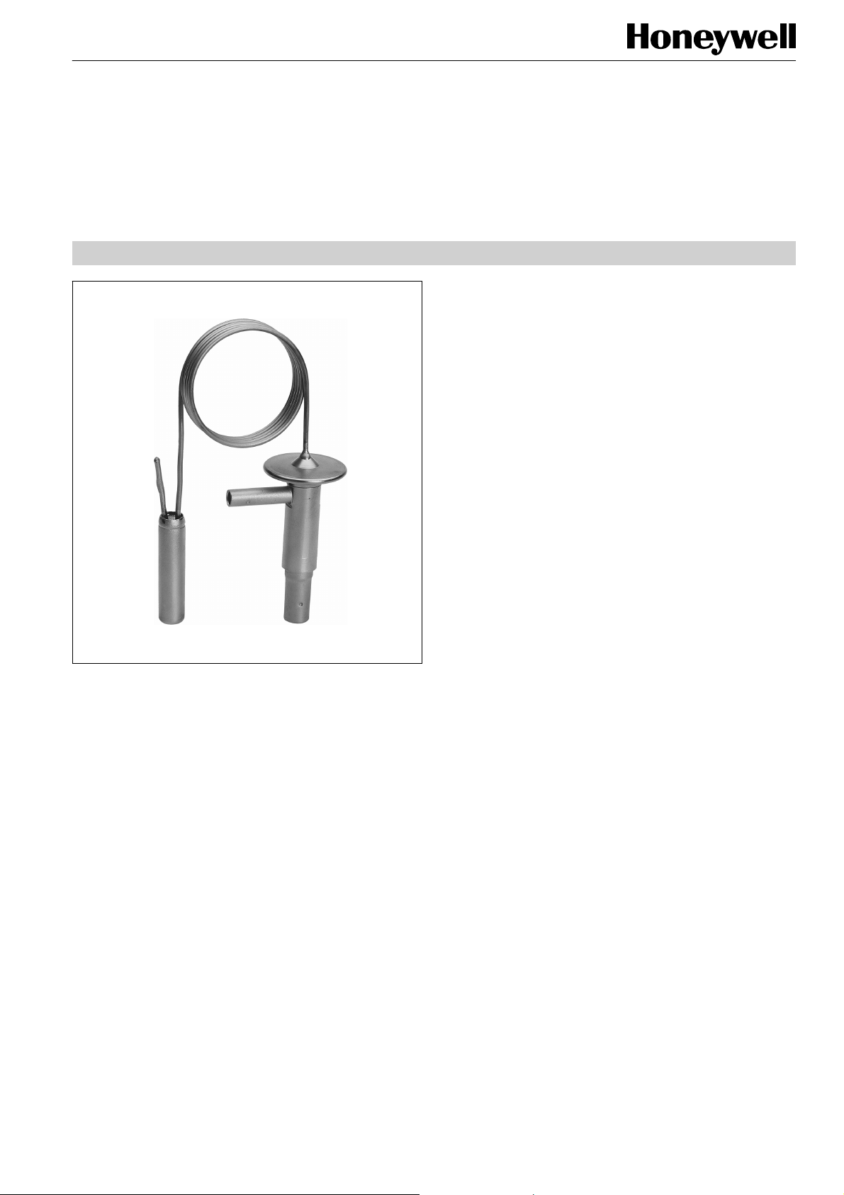
Series TLK
THERMOSTATIC EXPANSION VALVES
FIXED ORIFICE, FIXED SUPERHEAT SETTING
PRODUCT DATA
Features
• Gas charge with MOP for quick response time adapted
to small evaporators
• Wide evaporating temperature range
• Smallest dimensions
• Fixed superheat setting
• Warm thermal head provides best reliability
• Solder connections
• Internal pressure equalisation
• Extreme durable due to stainless steel head and
stainless steel diaphragm welded using protective gas
• Fixed orifice
• Bypass on request
• Refrigerants: R134a, R22, R404A, R407C, R507A
Further refrigerants on request.
Specification
Application
Thermostatic expansion valves series TLK are used for serial
produced systems such as drink dispensers, beer coolers, ice
cream machines, milk cooling units, water chillers and vehicle
air conditioning systems. For single injected evaporators.
Materials
Body
Thermal head
Connection tubes
brass
stainless steel
copper
Nominal capacity range
Evaporating temperature
range
Maximum pressure PS
Maximum test pressure PF
Max. ambient temperature
Max. bulb temperature
Static superheat
Length of capillary tube
Bulb diameter
0.52 to 4.0 kW R22
see table on page 2
see table on page 2
see table on page 2
100 °C
140 °C
approx. 4 K
1 m
12 mm
Copyright © 2009 Honeywell GmbH • Subject to change without notice EN0H-1911GE23 R0709
Page 2
SERIES TLK
Thermal Charges and Temperature Ranges
1. Gas charge with pressure limiting MOP
Refrigerant
R134a +15 °C to -40 °C MOP +15 °C 34 37.4
+10 °C to -40 °C MOP +10 °C 34 37.4
±0 °C to -40 °C MOP ±0 °C 29 31.9
R22 +15 °C to -45 °C MOP +15 °C 36 39.6
+10 °C to -45 °C MOP +10 °C 36 39.6
± 0 °C to -45 °C MOP ±0 °C 29 31.9
-18 °C to -45 °C MOP -18 °C 29 31.9
R404A +10 °C to -50 °C MOP +10 °C 36 39.6
±0 °C to -50 °C MOP ±0 °C 36 39.6
-18 °C to -50 °C MOP -18 °C 34 37.4
R407C +15 °C to -30 °C MOP +15 °C 36 39.6
+10 °C to -30 °C MOP +10 °C 36 39.6
R507A +10 °C bis -50 °C MOP +10 °C 36 39.6
Further refrigerants and MOP on request.
Evaporation
temperature
range
MOP PS
(bar(a))
PF
(bar(a))
MOP valves protect the compressor by limiting the increase
of suction pressure.
The MOP value should be chosen for the max. permissible
suction pressure of the compressor or min. 5 K higher than
the required evaporating temperature of the system.
For orders without any MOP indication a valve with MOP
+ 10 °C will be delivered.
With gas charged valves and MOP it is under all operating
conditions necessary that the bulb is always colder than the
capillary tube and the thermal head!
With the Honeywell TLK series the thermal head is heated
advantageously by the liquid refrigerant. The warm thermal
head is on the safe side at any time.
Capacities
Type Orifice size
0.3 0.36 0.52 0.36 0.50 0.36
0.5 0.69 0.99 0.68 0.95 0.69
TLK
* Capacities are based on t0 = +4 °C, tc = +38 °C and 1 K subcooled liquid refrigerant entering the valve.
For other operating conditions see capacity charts in Honeywell catalogue or consult the Honeywell software.
0.7 1.0 1.4 0.97 1.3 0.98
1.0 1.4 2.0 1.4 1.9 1.4
1.5 2.2 3.2 2.2 3.1 2.3
2.0 2.9 4.0 2.8 3.9 2.9
R134a R22 R404A R407C R507A
Nominal capacity (kW)*
Dimensions and Weights
Type
TLK
EN0H-1911GE23 R0709 2 Honeywell GmbH • Subject to change without notice
Orifice
size
0.3
0.5
0.7
1.0
1.5
2.0
Inlet
(A)
6 mm ODF 10 mm ODF
1/4" ODF 3/8" ODF
10 mm ODF 12 mm ODF
3/8" ODF 1/2" ODF
Connections
Outlet
(B)
Weight
(kg)
approx. 0.18
approx. 0.19
Page 3

SERIES TLK
TLK
Type Code / Order Information
TLK 0.5 R22 MOP +10 °C 6 mm x 10 mm
Series
Orifice size
Refrigerant
Gas charge with MOP
Solder connection ODF
(inlet x outlet)
Installation
• The valves may be installed in any position.
• The bulb should preferably be positioned on the upper half
of a horizontal suction line but never after a liquid trap. As
a general rule, bulbs of expansion valves should be
insulated to prevent them being affected by the ambient
temperature.
• In case of ice formation at the mounting site of the bulb,
we advise to use a bulb clamp instead of clips.
• When soldering the valve, the valve body must not get
warmer than 100 °C.
• Do not bend or squeeze the bulb.
• Constructive modifications at the valve are not allowed.
Information for original equipment manufacturers:
The valve series TLK can be customised to the
requirements of your series device in an optimum way.
Contact us!
Honeywell GmbH • Subject to change without notice 3 EN0H-1911GE23 R0709
Page 4

SERIES TLK
Automation and Control Solutions
Honeywell GmbH
Hardhofweg
74821 Mosbach/Germany
Phone: +49 (0)
Fax: +49 (0)
62 61 / 81-475
62 61 / 81-461
Manufactured for and on behalf of the
Environment and Combustion Controls
Division of Honeywell Technologies Sàrl,
1180 Rolle, Z. A. La Pièce 16, Switzerland
by its authorized representative Honeywell GmbH
E-Mail: cooling.mosbach@honeywell.com
KAT-TLK-002
www.honeywell-cooling.com
EN0H-1911GE23 R0709 4 Honeywell GmbH • Subject to change without notice
 Loading...