

69-2474EFS (Honeywell YTL9160 System Installation Guide).book Page 1 Friday, April 29, 2011 12:04 PM
System
Installation
Guide
TL9160 Wireless Thermostat Kit
With Equipment Interface Module
Français : voir la page 25 • Espagnol : vea la página 49
Installation guide for:
• Wireless equipment interface module
• TL9160 wireless thermostat
• Wireless remote control
• Wireless outdoor air sensor
IMPORTANT INSTRUCTIONS
ELECTRICAL HAZARD
Can cause electrical shock or equipment damage. Disconnect power
before beginning insta ll ation.
Must be installed by a trained, experienced technician. Read these
instructions carefully. Failure to follow these instructions can damage the
product or cause a hazardous condition .
Need Help?
For assistance with this product please visit http://customer.honeywell.com
or call Honeywell Customer Care toll-free at 1-800-468-1502.
69-2474EFS (Honeywell YTL9160 System Installation Guide).book Page 2 Friday, April 29, 2011 12:04 PM
Installation Guide
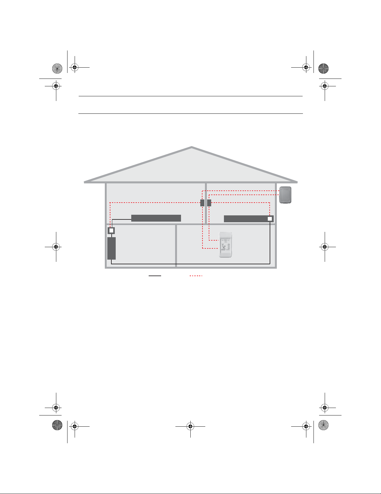
System installation at a glance
The equipment interface module (EIM) allows you to control a baseboard heater, a
convector or a fan-forced heater in 120-volt or 240-volt application from a TL916 0 wireless
thermostat
1.
EIM in remote
junction box
Electrical
panel
Thermostat
heater
Supply wires
Thermostat
Wireless connection
EIM inside heater
Remote
control
Outdoor
sensor
Installation procedure
Install the equipment interface module (EIM)........................................ ....... Pages 3 - 5
Install batteries in wireless devices..................................................................... Page 6
Link all devices to wireless network..................................... ... .. ... ................ Pages 6 - 9
Exit wireless setup............................................................................................Page 10
Customize thermostat (installer setup)..................................................... Pages 10 - 17
Mount thermostat and outdoor sensor..............................................................Page 18
For error codes, see page 19.
To verify the signal strength, see page 20.
To replace a wireless device, see page 20.
For specifications and replacement parts, see page 22.
SAVE THESE INSTRUCTIONS
2
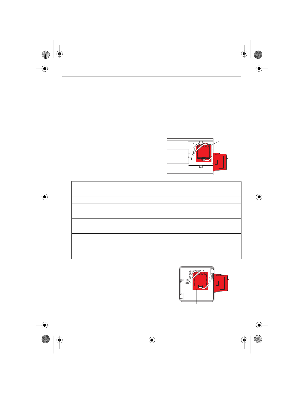
Relay
Antenna
Relay
Antenna
69-2474EFS (Honeywell YTL9160 System Installation Guide).book Page 3 Friday, April 29, 2011 12:04 PM
TL9160
Install the Equipment Interface Module (EIM)
Determine the location
The equipment interface module (EIM) consists of a relay and an antenna. They can b e
installed either in the wiring compartment of the baseboard heater or in a 4”x4” junction
box.
NOTE: Install EIMs at a minimum distance of 2 feet (0.6 m) of each other. This minimum
distance still applies even if the EIMs are on opposite sides of a wall.
• Installing the EIM in the bas eb oa r d heater
You can install the EIM in the wiring
compartment of the heater if you have any of
the heaters listed in the following table:
Manufacturer / brand Series
Cadet F
Global Commander CCB
King Electrical K, CB, KP, M
Marley 2500, BKOC, QMKC
Ouellet ODBA, ODI, ODIA, OFM, OPR
Stelpro CBB, N, SCA, SCAS
TPI 2900C, 2900S, 3700, 3900
NOTE: The product has been tested for compatibility with the heaters listed above. If
your heater is not in the list, install the EIM on an electrical box or replace it with one
listed.
2.
• Install the EIM in a 4”x4” elec tr ic a l box
Install the EIM in a 4”x4” electrical box:
• if you have a convector or fan-forced heater.
• if you cannot install or do not wish to install the
EIM in the wiring compartment of the heater.
NOTE: The electrical box can be inst alled anywhere
in the house; for example, near the main electrical
panel.
3
L2 L1 : For 240V application
N L : For 120V application
BlueBlue
BlackBlack
RedRed
Install plug if
applicable.
69-2474EFS (Honeywell YTL9160 System Installation Guide).book Page 4 Friday, April 29, 2011 12:04 PM
Installation Guide
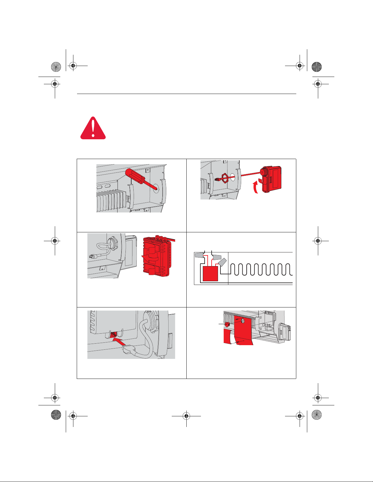
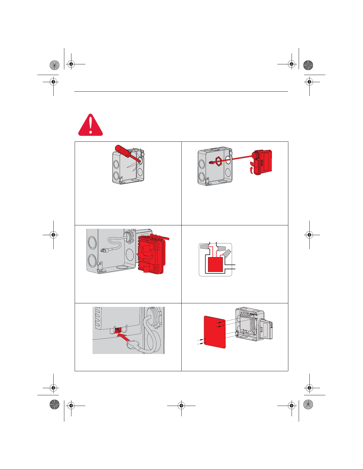
Installation in the heater
ELECTRICAL HAZARD
Can cause electrical shock or equipment damage. Disconnect AC power
before beginning installation.
Wiring must comply with local electrical codes. Use speci al CO/AL R sold erle ss
connectors if supply wires are made of aluminum.
NOTE: First, disconnect the heater wires from the supply wires. If the heater has a built-in
thermostat, remove it.
2) Remove the locknut from the antenna and
peel off the adhesive backing. Feed the
1) Remove the knockout on the side of the
heater.
antenna wires through the knockout and
install the antenna vertically as shown.
Put the locknut and tighten.
3) Peel off the adhesive backing of the relay
and stick the relay on the back panel
inside the wiring compartment with the
relay wires directed upwards.
5) Insert the antenna plug into the relay
receptacle until you hear a click.
4) Connect the heater wires and the supply
wires to the relay wires as shown.
6) Put the heater cover back. (If a built-in
thermostat was removed, install one of
the supplied plugs to cover the hole on the
existing cover .) Apply power t o the heater.
Do not install the antenna cover yet.
4
Blue
Black
Red
69-2474EFS (Honeywell YTL9160 System Installation Guide).book Page 5 Friday, April 29, 2011 12:04 PM
Installation in a 4”x4” junction box
ELECTRICAL HAZARD
Can cause electrical shock or equipment damage. Disconnect AC power
before beginning installation.
Wiring must comply with local electrical codes. Use speci al CO/AL R sold erle ss
connectors if the supply wires are made of aluminum.
TL9160
1) Mount the junction box on the wall. Pu nch
out a knockout on the side of the electr ical
box where the AC wires come in. Punch
out another one or two knockouts for the
heater and supply wires. Install strain
relief bushings.
3) Peel off the adhesive backing of the relay
module and stick the relay inside the
electrical box with the relay wires directed
upwards (as shown).
5) Insert the antenna plug in the relay
receptacle until you hear a click.
2) Remove the locknut from the antenna and
peel off the adhesive backing. Feed the
antenna wires through a knockout and
mount the antenna vertically as shown.
Put the locknut and tighten.
N L : For 120V application
L2 L1 : For 240V application
Red
Blue
Black
To heater
4) Feed the supply wires and heater wires
through a knockout and connect them to
the relay module.
6) Install a cover plate and apply power to
the heater. Do not put the antenna
cover back yet.
5
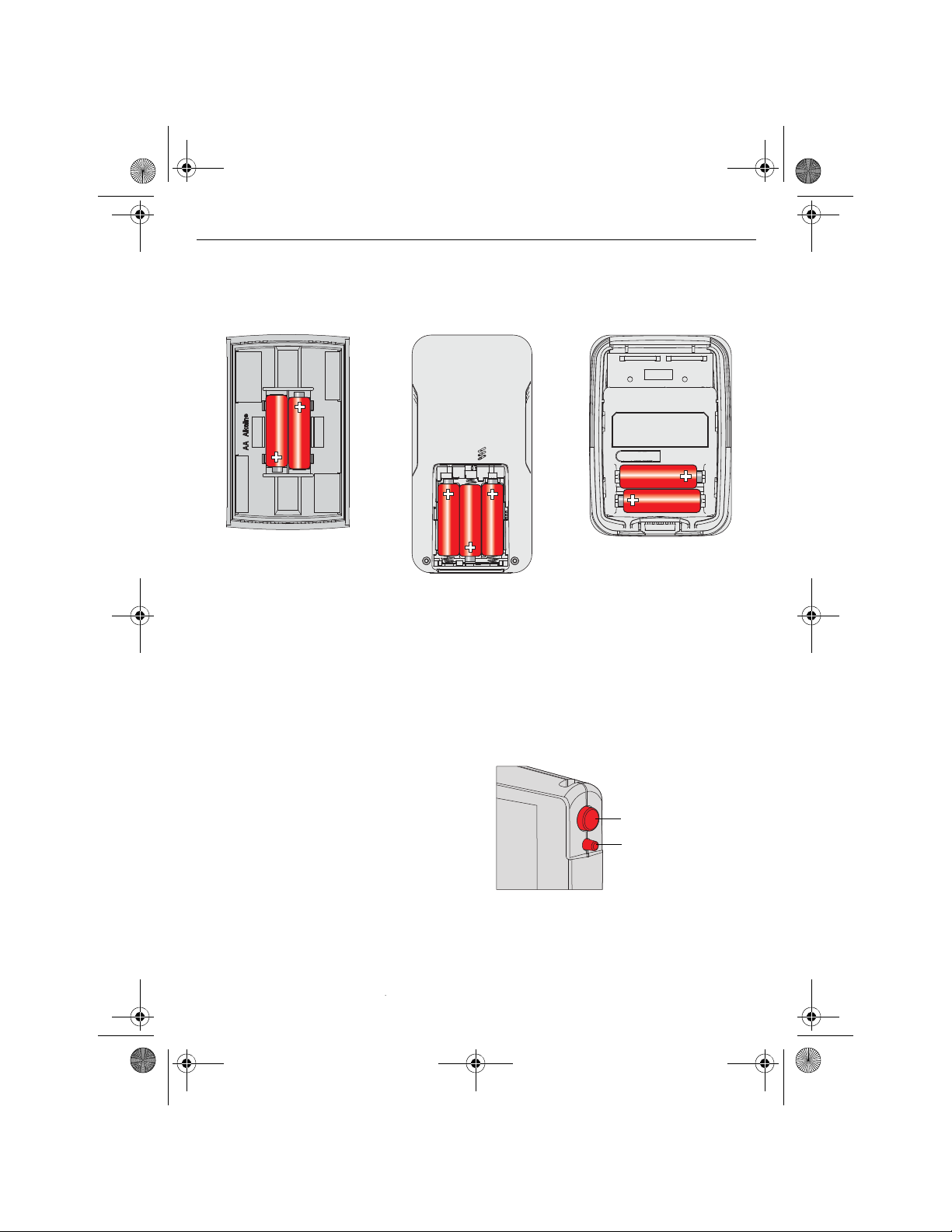
Press and release
* Flashing green: Ready for connection
Steady green: Connection established
Steady red: Connection failure
LED *
69-2474EFS (Honeywell YTL9160 System Installation Guide).book Page 6 Friday, April 29, 2011 12:04 PM
Installation Guide
Start wireless setup
Press the
light changes to a green flashing light, you can begin to link devices to the wireless network
(see pages 7-10).
Install batteries in wireless devices
Thermostat Remote control Outdoor air sensor
Install 2 AA alkaline batteries Install 3 AA alkaline batteries Install 2 AA lithium batteries
Link all devices to wireless network
CONNECT button on the antenna to place it in wireless setup. When the amber
3.
4.
NOTE 1: If the amber light changes to a red
light instead, there is another EIM currently in
wireless setup. Press the
the other EIM to exit its wireless setup.
NOTE 2: If the green flashing light disappears
(after a delay of 15 minutes) before you have
time to link all your devices, press the
CONNECT button again.
CONNECT button on
6
69-2474EFS (Honeywell YTL9160 System Installation Guide).book Page 7 Friday, April 29, 2011 12:04 PM
TL9160
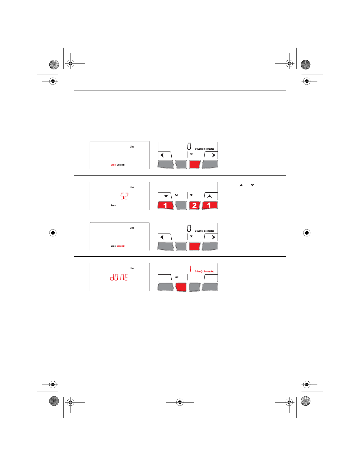
Link thermostat and EIM to wireless network
Perform the following steps on the thermostat:
NOTE: You can skip step 2 if you do not have a wireless remote control or do not have
more than one wireless thermostat in your house.
# Display Button Step
1)
2)
3)
4)
The Link menu appears
when you connect the
thermostat to wireless
network for the first time.
Press OK to select Zone.
Press or to change
the zone name (see page
15) and press OK.
Press OK to select
Connect.
DONE confirms the
connection is successful.
Press Exit once to link
another EIM (see page 8)
or 3 times to return to
home screen.
7
69-2474EFS (Honeywell YTL9160 System Installation Guide).book Page 8 Friday, April 29, 2011 12:04 PM
Installation Guide
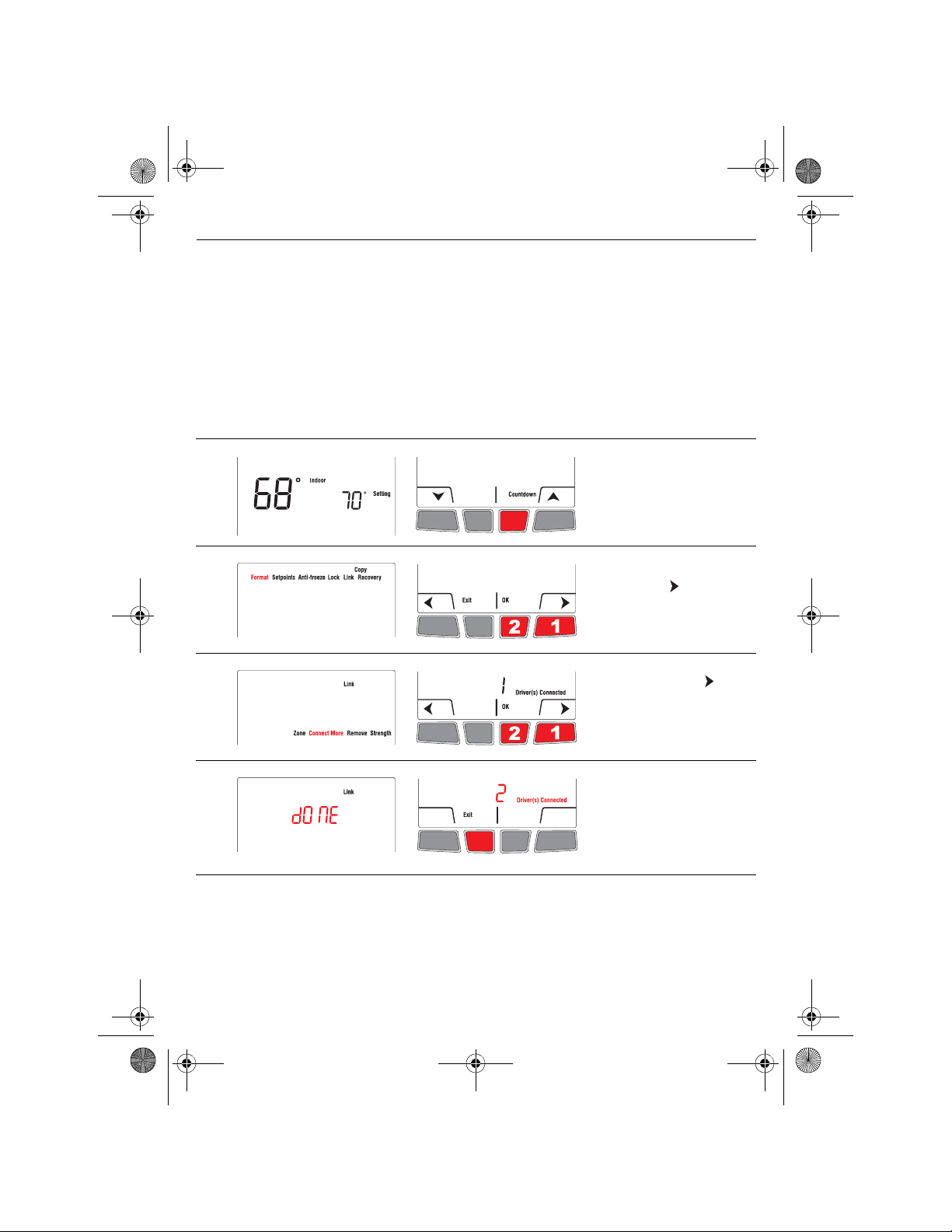
Link additional EIM to wireless network (if applicable)
NOTE: Perform steps 1 to 6 for each additional EIM. You can link a maximum of 8 EIMs to
the wireless neywork.
1) If the green light on the EIM that was last linked is still flashing, press its
CONNECT
button. The green light will become steady.
2) Press the CONNECT button on the next EIM you wish to link and wait for its green
flashing light.
NOTE: Skip steps 3 and 4 if the Link menu is still displayed on the thermostat (as
shown in step 5).
# Display Button Step
3)
Press and hold the right
center button for 5 secs.
4)
From the installer’s setup
menu, press to select
Link and press OK.
5)
If necessary, press to
select Connect More and
press OK.
6)
DONE appears to confirm
the connection is
successful. Press Exit and
go back to step 1 once to
link another EIM or 3 times
to return to home screen.
8
 Loading...