

Page 1
Installation
69-2019EFS-02
Guide
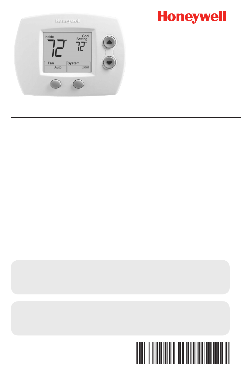
FocusPRO® TH5320C
Non-Programmable Digital Communicating Thermostat
To be used with up to 3 Heat 2 Cool conventional and heat pump systems with
W8835 Zone Panel or W8635 or THM5241 Equipment Interface Modules (EIM).
Use With
• W8835 Zone Panel—up to 3H/2C conventional or heat pump system
• W8635A EIM—up to 2H/2C conventional system
• W8635B EIM—up to 2H/1C heat pump system
• THM5421 EIM—up to 3H/2C conventional or heat pump
System Types
• Gas, oil, or electric heat with air
conditioning
• Warm air, hot water, highefficiency furnaces, heat pumps,
steam, gravity
• Heat only — two-wire systems,
three-wire zone valves (Series
20), and normally open zone
valves
• Heat only with fan
• Cool only
Must be installed by a trained, experienced technician
Read these instructions carefully. Failure to follow these instructions
can damage the product or cause a hazardous condition.
Need Help?
For assistance with this product please visit http://yourhome.honeywell.com
or call Honeywell Customer Care toll-free at 1-800-468-1502
® U.S. Registered Trademark. Patents pending.
Copyright © 2008 Honeywell International Inc.
All rights reserved.
Page 2
Installation Guide
M23800
M23799
1
2
3
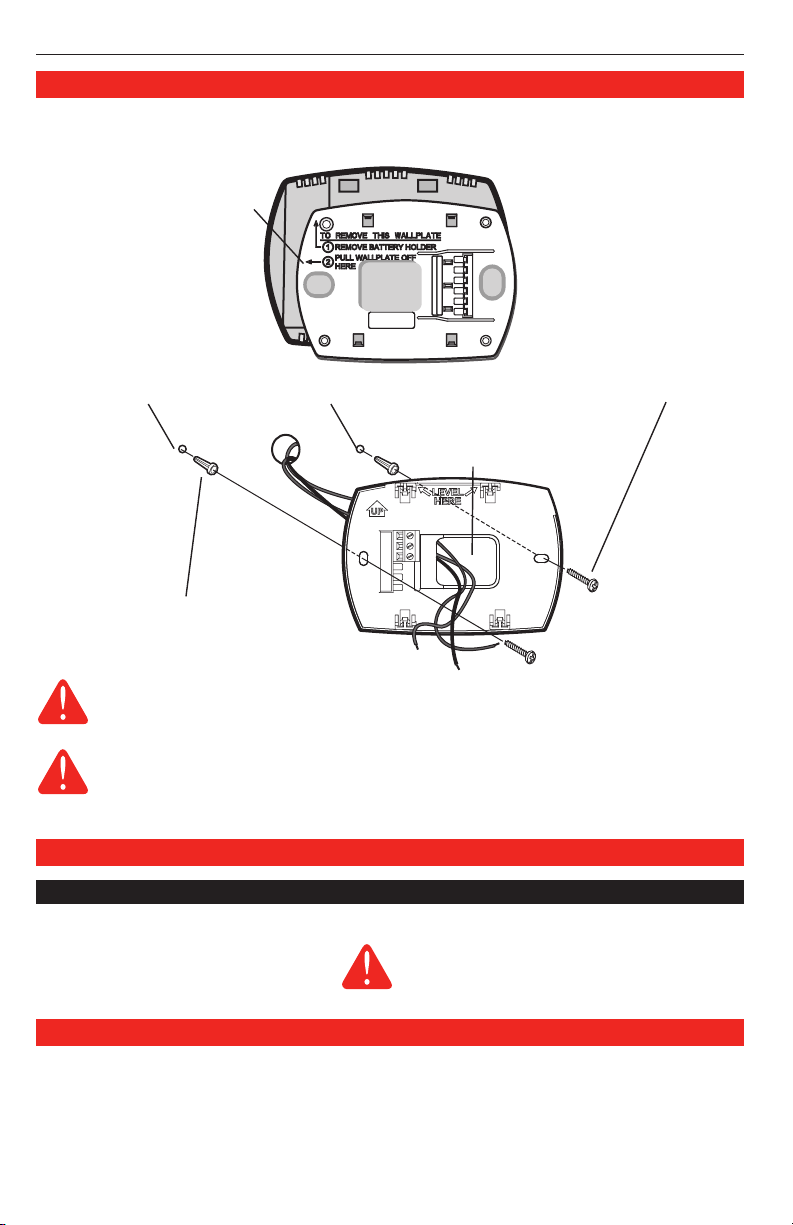
Wallplate installation
1. Separate wallplate from thermostat.
2. Mount wallplate as shown below.
Pull here to remove wallplate
from new thermostat.
Drill 3/16” holes for drywall. Drill 7/32” holes for plaster.
Wire hole
Wall anchors
Wallplate
CAUTION: ELECTRICAL HAZARD
Can cause electrical shock or equipment damage. Disconnect power before
beginning installation.
MERCURY NOTICE
If this product is replacing a control that contains mercury in a sealed tube, do not
place the old control in the trash. Contact your local waste management authority for
instructions regarding recycling and proper disposal.
Wiring
Terminal designations
Thermostat Terminals (connect to network zone panel or EIM):
1 Data communication
2 Power
3 Common
This thermostat does not use batteries.
Installing batteries could lead to corrosion of
the batteries and damage the thermostat.
Mounting screws
Thermostat mounting
Once wallplate is securely mounted on wall:
1. Push excess wire back into the wall opening.
2. Plug wall opening with non-flammable insulation.
3. Align the 4 tabs on the wallplate with the slots on the back of the thermostat.
4. Gently push the thermostat onto the wallplate; thermostat will snap into place.
69-2019EFS—02 2
Page 3
®
M23675
FocusPRO
TH5320
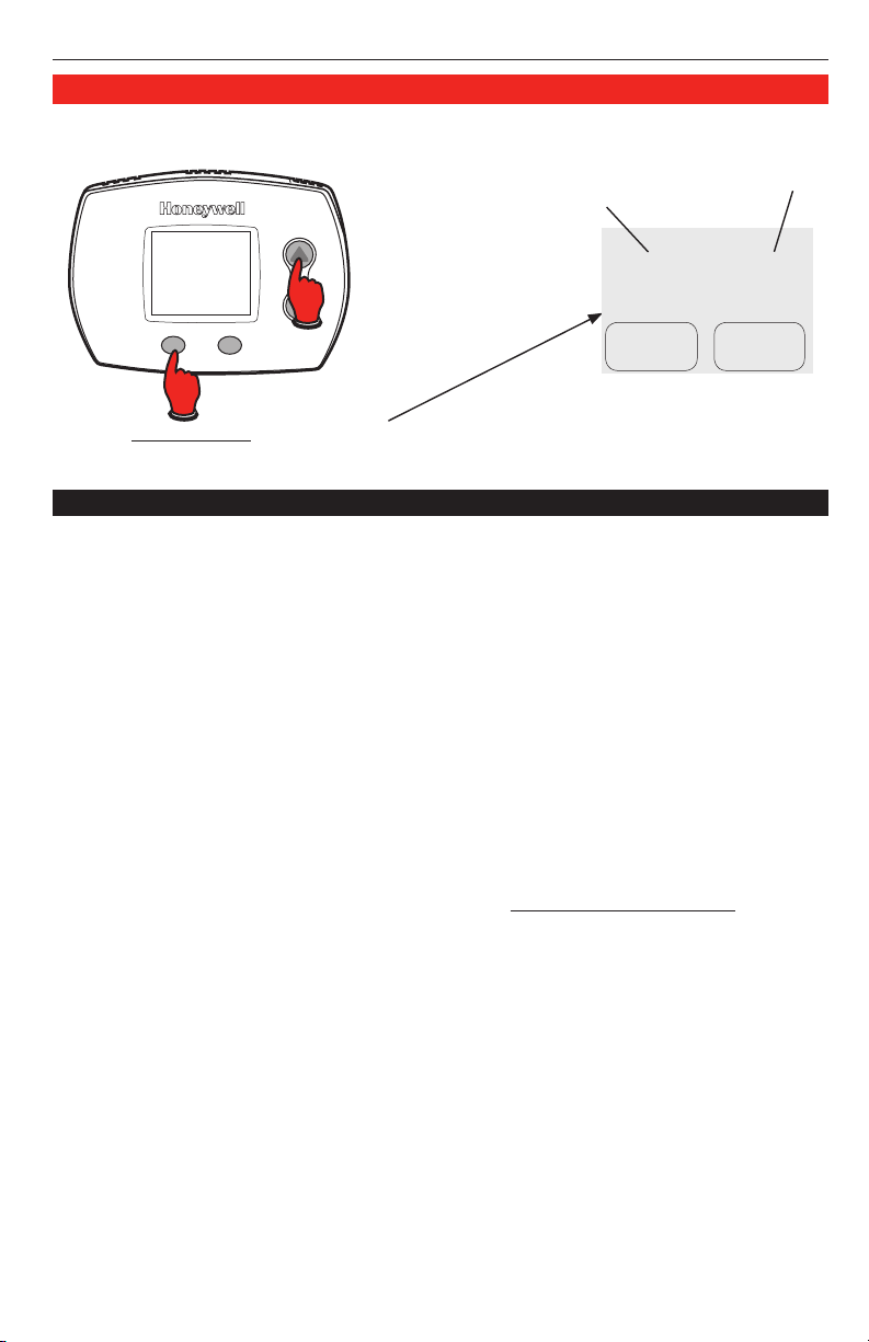
Installer setup
Follow the procedure below to configure the thermostat to match the installed heating/cooling
system, and customize feature operation as desired.
Function
number
Setting
1
Done Next
Press s or t to change settings.
To begin, press and hold the s and FAN
buttons until the display changes.
Setup function Settings & options (factory default in bold)
0 Zone Instance 0 Not Zoned
1 System type 0 1 heat/1 cool conventional
2 Changeover valve
(O/B terminal)
3 Fan control
(heating)
5 Stage 1 heat cycle
rate (CPH: cycles/hour)
6 Second Stage Heat
Cycle Rate
7 Third Stage Heat
Cycle Rate
8 Emergency Heat
Cycle Rate
1–9 Zoned (default setting 2)
1 1 heat/1 cool heat pump (no aux. heat)
2 Heat only — 2-wire systems, 3-wire zone valves (Series 20), and nor-
mally open zone valves
3 Heat only with fan
4 Cool only
5 2 heat/1 cool heat pump (with aux. heat)
6 2 heat/2 cool conventional
7 2 heat/1 cool conventional
8 1 heat/2 cool conventional
9 2 heat/2 cool heat pump (no aux. heat)
10 3 heat/2 cool heat pump (with aux. heat)
A Auto Discover
0 Changeover valve (O/B terminal energized in cooling)
1 Changeover valve (O/B terminal energized in heating)
0 Gas or oil furnace — equipment controls fan in heating
1 Electric furnace — thermostat controls fan in heating
5 For gas or oil furnaces of less than 90% efficiency
1 For steam or gravity systems
3 For hot water systems & furnaces of over 90% efficiency
9 For electric furnaces
5 Standard Gas or Oil Furnace
1 Steam or Gravity
3 90% + Efficient Furnace or Hot Water
9 Electric Furnace
[Other options: 2, 4, 6, 7, 8, 10, 11, 12 for Special Applications]
A Auto Discover
5 Standard Gas or Oil Furnace
1 Steam or Gravity
3 90% + Efficient Furnace or Hot Water
9 Electric Furnace
[Other options: 2, 4, 6, 7, 8, 10, 11, 12 for Special Applications]
A Auto Discover
9 Electric Furnace
[Other options: 1–8, 10, 11, 12 for Special Applications]
A Auto Discover
Press NEXT to advance to the next function.
Press DONE to exit and save settings.
0
3 69-2019EFS—02
Page 4
Installation Guide
Setup function Settings & options (factory default in bold)
9 Stage 1 compressor
cycle rate (CPH)
10 Second Stage
Compressor
Cycle Rate
12 Manual/Auto
changeover
14 Temperature
display
15 Compressor
protection
19 Service Indicator 00–199 Diagnostic Codes
23 Backlight Mode 0 Disabled
26 Aux Control 0 Comfort
27 Heat temperature
range stops
28 Cool temperature
range stops
3 Recommended for most compressors
[Other cycle rate options: 1, 2, 4, 5 or 6 CPH]
3 Compressor Cycle Rate
[Other options: 1, 2, 4, 5, 6 for Special Applications]
A Auto Discover
0 Manual changeover (Heat/Cool/Off)
1 Auto changeover (Heat/Cool/Auto/Off)
2 Auto changeover only (Auto)
0 Fahrenheit
1 Celsius
5 Five-minute compressor off time
[Other options: 0, 1, 2, 3 or 4-minute off time]
See Special function section on page 5.
1 Enabled
1 Economy
See Special function section on page 5.
90 Max. heat temperature setting is 90 °F (32 °C)
[Other options: 40 °F to 89 °F (4.5 °C to 31.5 °C)]
50 Min. cool temperature setting is 50 °F (10 °C)
[Other options: 51 °F to 99 °F (10.5 °C to 37 °C)]
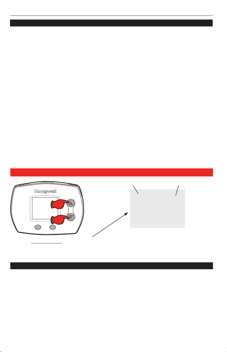
Installer system test
Test number
System status
To begin, press and hold the s and t
buttons until the display changes
Press s / t to turn system on/off.
Press NEXT to advance to next test.
Press DONE to terminate system test.
System test System status
10 Heating system 0 Heat and fan turn off.
20 Emergency heating
system
30 Cooling system 0 Compressor and fan turn off
40 Fan system 0 Fan turns off
69-2019EFS—02 4
1 Stage 1 heat turns on. Fan turns on if Setup Function 1 is set to 1,
5, 9 or 10 OR Setup Function 3 is set to 1.
2 Stage 2 heat turns on.
3 Stage 3 heat turns on.
0 Heat and fan turn off
1 Heat and fan turn on
1 Compressor and fan turn on
2 Stage 2 compressor turns on
1 Fan turns on
10
0
Page 5

®
FocusPRO
TH5320
System test System status
70 Thermostat information
(for reference only)
CAUTION: Compressor protection is bypassed during testing. To prevent equipment
damage, avoid cycling the compressor quickly
71 Software Revision Number (major revisions)
72 Software Revision Number (minor revisions)
73 Configuration Identification Number (major)
74 Configuration Identification Number (minor)
75 Production configuration date code (week)
76 Production configuration date code (year)
Special function
Auxiliary heat control (Setup Function 26):
• Comfort Setting: The thermostat will prioritize comfort over economy depending on heat
pump performance, load conditions and whether the thermostat is calling for the heat
pump. Raising the temperature just a few degrees will often activate the auxiliary heat.
• Economy Setting: The thermostat will attempt to reach the temperature setting
without activating the auxiliary heat. The thermostat will wait to activate the auxiliary
heat depending on heat pump performance, load conditions and how many degrees the
temperature setting is changed.
Diagnostic Codes (Setup Function 19):
When Error Codes are present the home screen of the thermostat will display “SERVICE NEEDED”
and scroll through all active error codes. Setup Function 19 will display a list of the 10 most recent
error codes, both active and inactive. The number on the right of the thermostat will show the
number of active and inactive error codes saved in the thermostat. To view the error codes press
the up arrow. To clear the list, press and hold both the up and down arrow keys. Active errors can
not be cleared; the source of the error must be resolved prior to clearing from the list.
Accessories & replacement parts
Please contact your distributor to order replacement parts.
Part Description Part Number
Small cover plate assembly* 50001137-001
Medium cover plate assembly* 50002883-001
12 pack of small cover plates* 50007297-001
12 pack of medium cover plates* 50007298-001
EnviraZONE Zone panel W8835A1004
Equipment Interface Module for 2H/2C conventional systems W8635A1006
Equipment Interface Module for 2H/2C heat pump systems W8635B1004
Telephone Access Module W8735B1003
2-Channel Telephone Access Module W8735D1009
4-Channel Telephone Access Module W8735D1017
*Use to cover marks left by old thermostats.
Specifications
Temperature Ranges
• Heat: 40° to 90°F (4.5° to 32°C)
• Cool: 50° to 99°F (10° to 37°C)
Operating Ambient Temperature
• 32° to 120°F (0° to 48.9°C)
Shipping Temperature
• -20° to 120°F (-28.9° to 48.9°C)
5 69-2019EFS—02
Operating Relative Humidity
• 5% to 90% (non-condensing)
Physical Dimensions
TH5220D
• 3-9/16” H x 5-13/16” W x 1-1/2” D
91 mm H x 147 mm W x 38 mm D
TH5110D
• 3-7/16” H x 4-1/2” W x 1-5/16” D
86 mm H x 114 mm W x 33 mm D
Page 6

Guide
d’installation
FocusPRO® TH5320C
Thermostat numérique non programmable avec fonction de communication
Convient aux systèmes de chauffage classiques et aux thermopompes à 3 étages de
chauffage et 2 étages de refroidissement avec tableau de zonage W8835 ou W8635
ou modules d’interface THM5241.
À utiliser avec
• Tableau de zonage W8835—Systèmes classiques ou thermopompes jusqu’à
3C/2R
• Module d’interface W8635A—systèmes classiques jusqu’à 2C/2R
• Module d’interface W8635B —thermopompes jusqu’à 2C/1R
• Module d’interface THM5421—systèmes classiques ou thermopompes jusqu’à
3C/2R
Types de système
• Chauffage au gaz naturel,
au mazout ou à l’électricité
avec climatiseur
• Appareils de chauffage à haute
efficacité à air chaud ou à eau
chaude; thermopompes, systèmes
à vapeur ou à gravité
• Chauffage seulement – systèmes
à deux fils, vannes de zone
à trois fils (Série 20) vannes
de zones normalement ouvertes
• Chauffage seulement avec
ventilation
• Refroidissement seulement
Doit être installé par un technicien expérimenté et qualifié.
Lire attentivement ces instructions. Le manquement à suivre ces instructions
peut entraîner des dommages au produit et causer des conditions dangereuses.
Besoin d’aide?
Pour obtenir de l’assistance au sujet de ce produit,
consulter le http://yourhome.honeywell.com ou téléphoner sans frais
au Centre de service à la clientèle de Honeywell au 1 800 468-1502
® Marque de commerce déposée aux É.-U. Brevets en instance.
© 2008 Honeywell International Inc.
Tous droits réservés.
Page 7

Installation de la plaque murale
M23799
1
2
3
M23800
1. Séparer la plaque murale du thermostat.
2. Installer la plaque murale tel qu'il est décrit ci-dessous.
Tirer ici pour enlever la plaque
murale du thermostat neuf.
Percer des trous de 5 mm (3/16 po) dans le placoplâtre.
Percer des trous de 5,5 mm (7/32 po) si le mur est en plâtre.
Trou du fil
Chevilles d'ancrage
FocusPRO
Vis de montage
®
TH5320C
Plaque murale
MISE EN GARDE : RISQUE DE CHOC ÉLECTRIQUE
Peut causer un choc électrique ou endommager l’équipement. Couper l’alimentation
avant de commencer l’installation.
AVIS SUR LE MERCURE :
Si le présent thermostat remplace un thermostat contenant du mercure dans une ampoule
scellée, ne pas jeter l’ancien thermostat à la poubelle. Communiquer plutôt avec le service
local de cueillette des déchets pour obtenir de l’information sur le recyclage ou sur la
bonne façon de disposer d’un ancien régulateur contenant un contact à mercure.
Câblage
Désignation des bornes
Bornes du thermostat (pour raccordement au tableau de zonage en réseau ou au
module d’interface) :
1 Transmission de données
2 Alimentation
3 Commun
Ce thermostat ne requiert aucune pile. L’installation
de piles pourrait mener à la corrosion des piles et
causer des dommages au thermostat.
Installation du thermostat
Une fois la plaque murale solidement fixée au mur :
1. Repousser le fil en excès dans l’ouverture dans le mur.
2. Boucher l’ouverture dans le mur au moyen d’un isolant ininflammable.
3. Faire correspondre les quatre languettes de la plaque murale avec les quatre fentes au
dos du thermostat.
4. Pousser doucement le thermostat en ligne droite sur la plaque murale : le thermostat se
mettra en place.
7 69-2019EFS—02
Page 8

Guide d’installation
M23675
Configuration du système
Suivre les directives ci-dessous pour configurer le thermostat pour qu’il corresponde au système
de chauffage-refroidissement installé, et pour personnaliser son fonctionnement.
Numéro de fonction Réglage
Appuyer sur s ou t pour modifier les
Pour commencer, appuyer sur les touches
s et FAN et les maintenir enfoncées
jusqu'à ce que l’affichage change.
réglages. Appuyer sur NEXT pour passer à la
fonction suivante. Appuyer sur DONE pour quitter
la configuration et enregistrer les réglages.
Fonction de Réglages et options
configuration (réglages par défaut en gras)
0 Zone 0 Aucune
1 Type de système 0 Classique 1 chauff./1 refroid.
2 Vanne d’inversion
(Borne O/B)
3 Commande du
ventilateur (chauffage)
5 Nombre de cycles par
heure du 1er étage de
chauffage
(CPH : cycles/heure)
6 Nombre de cycles par
heure du 2e étage de
chauffage
7 Nombre de cycles par
heure du 3e étage de
chauffage
8 Cycles de fonc-
tionnement du chauffage
d’urgence
69-2019EFS—02 8
1–9 Zoné (réglage par défaut 2)
1 Thermopompe 1 chauff./1 refroid. (sans chauffage auxiliaire)
2 Chauffage seulement — systèmes bifilaires, vannes de zone à 3 fils
(série 20), et vannes de zone normalement ouvertes
3 Chauffage seulement avec ventilateur
4 Refroidissement seulement
5 Thermopompe 2 chauff./1 refroid. (avec chauffage auxiliaire)
6 Classique 2 chauff./2 refroid.
7 Classique 2 chauff./1 refroid.
8 Classique 1 chauff./2 refroid.
9 Thermopompe 2 chauff./2 refroid. (sans chauffage auxiliaire)
10 Thermopompe 3 chauff./2 refroid. (avec chauffage auxiliaire)
A Auto-découverte
0 Vanne d’inversion (borne O/B sous tension en refroidissement)
1 Vanne d’inversion (borne O/B sous tension en chauffage)
0 Appareil de chauffage au gaz ou au mazout — le système com-
mande le ventilateur en mode de chauffage
1 Système de chauffage électrique – le thermostat commande le venti-
lateur en mode de chauffage
5 Pour les appareils au gaz ou au mazout à moins de 90 %
d’efficacité
1 Pour systèmes à vapeur ou à gravité
3 Pour systèmes à eau chaude et appareils de chauffage à plus de 90
% d’efficacité
9 Pour appareils de chauffage électriques
5 Appareil de chauffage standard au gaz ou au mazout
1 Vapeur ou gravité
3 Appareil de chauffage à 90 % d’efficacité ou eau chaude
9 Appareil de chauffage électrique
[Autres choix : 2, 4, 6, 7, 8, 10, 11, 12 pour applications spéciales]
A Auto-découverte
5 Appareil de chauffage standard au gaz ou au mazout
1 Vapeur ou gravité
3 Appareil de chauffage à 90 % d’efficacité ou eau chaude
9 Appareil de chauffage électrique
[Autres choix : 2, 4, 6, 7, 8, 10, 11, 12 pour applications spéciales]
A Auto-découverte
9 Appareil de chauffage électrique
[Autres choix : 1–8, 10, 11, 12 pour applications spéciales]
A Auto-découverte
1
Done Next
0
Page 9

Fonction de Réglages et options
M23675
configuration (réglages par défaut en gras)
9 Cycles de fonc-
tionnement du 1er étage
du compresseur
10 Cycles de fonc-
tionnement du 2e
étage du compresseur
12 Commutation
chaud-froid
automatique/manuelle
14 Affichage de la
température
15 Protection du
compresseur
19 Indicateur de service 00–199 Codes de diagnostic
23 Rétroéclairage 0 Désactivé
26 Commande auxiliaire 0 Confort
27 Butées d’arrêt de la
température de chauff.
28 Butées d’arrêt de la
température de refroid.
3 Recommandé pour la plupart des compresseurs
[Autres choix : 1, 2, 4, 5 ou 6 CPH]
3 Nombre de cycles de fonctionnement du compresseur
[Autres choix : 1, 2, 4, 5, 6 pour applications spéciales]
A Auto-découverte
0 Commutation chaud-froid manuelle (chauff./refroid./arrêt)
1 Commutation chaud-froid automatique (chauff., refroid., automatique,
arrêt)
2 Commutation chaud-froid automatique seulement (Auto)
0 Fahrenheit
1 Celsius
5 Temporisation de 5 minutes avant la mise en marche du com-
presseur
[Autres choix : temporisation de 1, 2, 3, ou 4 minutes]
Voir la section sur les fonctions spéciales en page 10.
1 Activé
1 Économique
Voir la section sur les fonctions spéciales en page 10.
90 Le point de consigne maximum de chauff. est de 32 °C (90 °F)
[Autres choix : 4,5 °C à 31,5 °C (40 °F à 89 °F)]
50 Le point de consigne minimum en refroid. et de 10 °C (50 °F)
[Autres choix : 10,5 °C à 37 °C (51 °F à 99 °F)]
FocusPRO
®
TH5320C
Essai de la configuration du système
Numéro d’essai État du système
10
Appuyer sur s / t pour activer ou désactiver le
Pour commencer, appuyer sur les touches
s et t et les maintenir enfoncées
jusqu'à ce que l’affichage change.
Essai du système État du système
10 Système de chauffage 0 Le système de chauffage et le ventilateur se mettent à l’arrêt.
20 Chauffage d’urgence 0 Le système de chauffage et le ventilateur se mettent à l’arrêt.
30 Système de
refroidissement
9 69-2019EFS—02
1 Le premier étage de chauffage se met en marche. Le ventilateur se
met en marche si le paramètre 1 est réglé à 1, 5, 9 ou 10 OU si le
paramètre 3 est réglé à 1.
2 Le deuxième étage de chauffage se met en marche.
3 Le troisième étage de chauffage se met en marche.
1 Le système de chauffage et le ventilateur se mettent en marche.
0 Le compresseur et le ventilateur se mettent à l’arrêt.
1 Le compresseur et le ventilateur se mettent en marche.
2 Le deuxième étage du compresseur se met en marche.
système.
Appuyer sur NEXT pour passer à l’essai suivant.
Appuyer sur DONE pour terminer l’essai du
système.
0
Page 10

Guide d’installation
Essai du système État du système
40 Ventilateur 0 Le ventilateur se met à l’arrêt.
70 Information sur le ther-
mostat (Pour référence
seulement)
MISE EN GARDE : Le système ne tient pas compte du temps d’arrêt minimal
du compresseur pendant l'essai. Pour éviter d’endommager le matériel, éviter les
cycles de fonctionnement trop rapides du compresseur.
1 Le ventilateur se met en marche
71 Numéro de révision du logiciel (révisions majeures)
72 Numéro de révision du logiciel (révisions mineures)
73 Code d’identification de la configuration (majeure)
74 Code d’identification de la configuration (mineure)
75 Code de date de la configuration à la fabrication (semaine)
76 Code de date de la configuration à la fabrication (année)
Fonction spéciale
Commande de chauffage auxiliaire (Fonction de configuration 26) :
• Réglage de confort : Le thermostat donne la priorité au confort plutôt qu'à l'économie
d'énergie selon le rendement de la thermopompe, la charge, la demande de mise
en marche de la thermopompe par le thermostat. En règle générale, augmenter la
température de quelques degrés seulement active le chauffage auxiliaire.
• Réglage d’économie : Le thermostat tente d’atteindre la température voulue sans
activer le chauffage auxiliaire. Le thermostat attendra avant d’activer le chauffage
auxiliaire en fonction du rendement de la thermopompe, de la charge et de l’écart
de modification du réglage de température.
Codes de diagnostic (Configuration du paramètre 19) :
En présence de codes d’erreur, l’écran d’accueil du thermostat affiche les mots «SERVICE
NEEDED» (entretien requis) et fait défiler tous les codes d’erreur actifs. Le paramètre 19 affiche
une liste des dix codes d’erreur les plus récents, tant actifs qu’inactifs. Le chiffre figurant à droite
de l’écran indique le nombre de codes d’erreur actifs et inactifs enregistrés. Pour voir les codes
d’erreur, appuyer sur la flèche vers le haut. Pour effacer la liste, appuyer sur les flèches vers le haut
et vers le bas en même temps et les tenir enfoncées. Il est impossible d’effacer les codes d’erreur
actifs; il faut d’abord corriger la source de l’erreur avant de pouvoir effacer un code de la liste.
Accessoires et pièces de rechange
Prière de communiquer avec le distributeur pour commander des pièces de remplacement.
Description des pièces N° de pièce
Petite plaque de recouvrement* 50001137-001
Plaque de recouvrement moyenne* 50002883-001
Paquet de 12 petites plaques de recouvrement* 50007297-001
Paquet de 12 plaques de recouvrement moyennes* 50007298-001
Tableau de zonage EnviraZONE W8835A1004
Module d’interface pour systèmes classiques 2C/2R W8635A1006
Module d’interface pour thermopompes 2C/2R W8635B1004
Module d’accès téléphonique W8735B1003
Module d’accès téléphonique à deux voies W8735D1009
Module d’accès téléphonique à quatre voies W8735D1017
*Sert à couvrir les marques laissées par l’ancien thermostat.
Spécifications
Gammes de température
• Chauffage : 4,5 ° à 32 °C (40 ° à 90 °F)
• Refroidissement : 10 ° à 37 °C
(50 ° à 99 °F)
Température ambiante
de fonctionnement
• 0 ° à 48,9 °C (32 ° à 120 °F)
Température d’expédition
• -28,9 ° à 48,9 °C (-20 ° à 120 °F)
69-2019EFS—02 10
Humidité relative
de fonctionnement
• 5 % à 90 % (sans condensation)
Dimensions
TH5220D
• 3-9/16 po H x 5-13/16 po L x 1-1/2 po P
91 mm H x 147 mm L x 38 mm P
TH5110D
• 3-7/16 po H x 4-1/2 po L x 1-5/16 po P
86 mm H x 114 mm L x 33 mm P
Page 11

Guía de
instalación
FocusPRO® TH5320C
Termostato de comunicación digital no programable
Para ser utilizado con sistemas convencionales de hasta 3 calentadores y 2 refrigeradores, con sistemas de bomba de calor con un panel de zona W8835 o W8635, o con
módulos de interfaz de equipo (EIM) THM5241.
Se usa con
• Un panel de zona W8835 (sistema convencional de hasta 3 calentadores y 2
refrigeradores o sistema de bomba de calor)
• W8635A EIM (sistema convencional de hasta 2 calentadores y 2 refrigeradores)
• W8635B EIM (sistema de bomba de calor de hasta 2 calentadores y 1
refrigerador)
• THM5421 EIM (sistema convencional de hasta 3 calentadores o bomba de calor)
Tipos de sistema
• Sistema de calefacción a gas,
a aceite o eléctrico con aire
acondicionado
• Calefacción de aire, agua caliente,
sistemas de calefacción de alta
efectividad, bombas de calor,
vapor, gravedad
• Sólo calor: sistemas de dos cables,
válvulas de separación de tres
cables (serie 20) y válvulas de
separación normalmente abiertas
• Sólo calor con ventilador
• Sólo frío
Debe ser instalado por un técnico
capacitado y experimentado
Lea estas instrucciones atentamente. Si no sigue estas instrucciones,
puede dañar el producto u ocasionar un riesgo.
¿Necesita asistencia?
Para obtener asistencia relacionada con este producto,
visite http://yourhome.honeywell.com o comuníquese con el número gratuito
del Centro de atención al cliente de Honeywell, llamando al 1-800-468-1502
® Marca registrada de los EE. UU. Patentes en trámite.
© 2008, Honeywell International Inc.
Todos los derechos reservados.
Page 12

Guía de instalación
M23800
M23799
1
2
3
Instalación de la placa para pared
1. Quite la placa para pared del termostato.
2. Monte la placa para pared como muestra la ilustración de abajo.
Hale de aquí para quitar
la placa para pared del
nuevo termostato.
En tablarroca, realice agujeros de 3/16". En yeso, realice agujeros de 7/32".
Agujero para el cable
Tornillos de montaje
Anclas de expansión
Placa para pared
PRECAUCIÓN: RIESGO ELÉCTRICO
Puede ocasionar descargas eléctricas o dañar el equipo. Desconéctelo de la fuente
de energía antes de comenzar la instalación.
AVISO SOBRE EL MERCURIO
En caso de que este producto reemplace a un control que contenga mercurio
en tubo sellado, evite arrojar el viejo control a la basura. Póngase en contacto con
la autoridad local para el manejo de desechos a fin de obtener instrucciones sobre
el reciclado y la correcta eliminación de este tipo de desechos.
Cableado
Designación de terminales
Terminales del termostato (conéctelos al panel de zona o al EIM):
1 Transmisión de datos
2 Alimentación
3 Común
Este termostato no usa baterías. La instalación de
baterías puede provocar la corrosión de éstas y
dañar el termostato.
Montaje del termostato
Una vez que la placa para pared esté montada en forma segura en la pared:
1. Coloque el excedente de cable en el interior de la abertura de la pared.
2. Tape la abertura de la pared con un aislamiento no inflamable.
3. Alinee las 4 lengüetas de la placa para pared con las ranuras de la parte posterior del
termostato.
4. Presione suavemente el termostato para introducirlo en la placa para pared. El
termostato encajará en su lugar.
69-2019EFS—02 12
Page 13

®
M23675
FocusPRO
TH5320C
Configuración de instalación
Siga el procedimiento que aparece a continuación para configurar el termostato a fin de que se
corresponda con el sistema de calefacción y refrigeración instalado, y seleccione las funciones
según lo desee.
Configuración
0
Para comenzar, pulse y mantenga
presionados los botones s y “FAN”
hasta que cambie la pantalla.
Número de función
1
Done Next
Presione s o t para cambiar la configuración.
Presione NEXT para avanzar a la siguiente función.
Presione DONE para salir y guardar la configuración.
Funciones de la Configuraciones y opciones (las que vienen
configuración desde la fábrica aparecen en negrita)
0 Ejemplo de zona 0 Sin división de zona
1 Tipo de sistema 0 1 convertidor de calor/frío
2 Válvula inversora
(terminal O/B)
3 Control del venti-
lador (calefacción)
5 Velocidad del
ciclo térmico de
la etapa 1 (CPH:
ciclos por hora)
6 Velocidad del
ciclo térmico de la
etapa 2
7 Velocidad del
ciclo térmico de la
etapa 3
8 Velocidad del ciclo
térmico de emergencia
13 69-2019EFS—02
1 a 9 Con división de zona (configuración predeterminada: 2)
1 Bomba de calor para 1 calentador y 1 refrigerador (sin calentador auxiliar)
2 Sólo calor: sistemas de 2 cables, válvulas de separación de zonas de 3 cables
(serie 20) y válvulas de separación normalmente abiertas
3 Sólo calor con ventilador
4 Sólo frío
5 Bomba de calor para 2 calentadores y 1 refrigerador (con calentador auxiliar)
6 2 calentadores y 2 enfriadores convencionales
7 2 calentadores y 1 enfriador convencionales
8 1 calentador y 2 enfriadores convencionales
9 Bomba de calor para 2 calentadores y 2 refrigerador (sin calentador auxiliar)
10 Bomba de calor para 3 calentadores y 2 refrigerador (con calentador auxiliar)
A Auto Discover (descubrimiento automático)
0 Válvula inversora (terminal O/B con energía durante la refrigeración)
1 Válvula inversora (terminal O/B con energía durante la calefacción)
0 Sistema de calefacción a gas o a aceite (el equipo controla el ventila-
dor para calefacción)
1 Sistema de calefacción eléctrico (el termostato controla el ventilador para
calefacción)
5 Para sistemas de calefacción a gas o a aceite de menos de un 90%
de efectividad
1 Para sistemas de vapor o de gravedad
3 Para sistemas de agua caliente y sistemas de calefacción de más de un
90% de efectividad
9 Para sistemas de calefacción eléctricos
5 Sistema de calefacción a gas o a aceite estándar
1 Sistemas de vapor o gravedad
3 Sistemas de calefacción de más del 90% de efectividad o de agua caliente
9 Sistema de calefacción eléctrico
[Otras opciones: 2, 4, 6, 7, 8, 10, 11, 12, para aplicaciones especiales]
A Auto Discover (descubrimiento automático)
9 Sistema de calefacción eléctrico
[Otras opciones: 2, 4, 6, 7, 8, 10, 11, 12, para aplicaciones especiales]
A Auto Discover (descubrimiento automático)
Page 14

Guía de instalación
Funciones de la Configuraciones y opciones (las que vienen
configuración desde la fábrica aparecen en negrita)
9 Velocidad del ciclo
térmico
1 (CPH)
10 Velocidad del ciclo
térmico
de la etapa 2
12 Conversión
manual o
automática
14 Visor de
temperatura
15 Protección del
compresor
19 Indicador de
mantenimiento
23 Modo de ilumi-
nación posterior
26 Controles
auxiliares
27 Limitadores de los
rangos de temperatura del sistema
de calefacción
28 Limitadores de los
rangos de temperatura del sistema
de refrigeración
3 Recomendada para la mayoría de los compresores
[Otras opciones de rango de ciclos: 1, 2, 4, 5 ó 6 CPH]
3 Rango de ciclos del compresor
[Otras opciones: 1, 2, 4, 5, 6, para aplicaciones especiales]
A Auto Discover (descubrimiento automático)
0 Conversión manual (calor/frío/apagado)
1 Conversión automática (calor/frío/automático/apagado)
2 Sólo conversión automática (Auto)
0 Fahrenheit
1 Celsius
5 Tiempo de apagado de 5 minutos para el compresor
[Otras opciones: 0, 1, 2, 3 ó 4 minutos de tiempo de apagado]
00–199 Códigos de diagnóstico
Vea la sección Funciones especiales, en la página 15.
0 Deshabilitado
1 Habilitado
0 Confort
1 Economía - Vea la sección Funciones especiales, en la página 15.
90 La configuración máxima de calefacción es 90 ºF (32 ºC)
[Otras opciones: de 40 °F a 89 °F (de 4,5 °C a 31,5 °C)]
50 La configuración mínima de calefacción es 50 °F (10 °C)
[Otras opciones: de 51 °F a 99 °F (de 10,5 °C a 37 °C)]
Prueba del sistema
Número de prueba Estado del sistema
10
Para comenzar, pulse y mantenga
presionados los botones s y t
hasta que cambie la pantalla
Prueba del sistema Estado del sistema
10 Sistema de calefacción 0 El calentador y el ventilador se apagan
20 Sistema de calefacción
de emergencia
30 Sistema de
refrigeración
40 Sistema del ventilador 0 El ventilador se apaga
69-2019EFS—02 14
1 El calentador de la etapa 1 se enciende El ventilador se enciende
2 El calentador de la etapa 2 se enciende
3 El calentador de la etapa 3 se enciende
0 El calentador y el ventilador se apagan
1 El calentador y el ventilador se encienden
0 El compresor y el ventilador se apagan
1 El compresor y el ventilador se encienden
2 El compresor de la etapa 2 se enciende
1 El ventilador se enciende
Presione s / t para encender o apagar el sistema.
Presione “NEXT” para avanzar hacia la próxima prueba.
Presione “DONE” para finalizar la prueba del sistema.
si la función 1 de la configuración se coloca en 1, 5, 9 ó 10, o si la
función 3 de la configuración se coloca en 1
0
Page 15

®
FocusPRO
TH5320C
Prueba del sistema Estado del sistema
70 Información del ter-
mostato (únicamente
como referencia)
PRECAUCIÓN: Durante la prueba, se desactiva la protección del compresor. Para evitar
daños en el equipo, no permita que el compresor funcione a velocidades altas.
71 Número de revisión de software (revisiones mayores)
72 Número de revisión de software (revisiones menores)
73 Código de identificación de configuración (mayor)
74 Código de identificación de configuración (menor)
75 Código de configuración de fecha de producción (semana)
76 Código de configuración de fecha de producción (año)
Funciones especiales
Control de calor auxiliar (configuración 26):
• Configuración comfort: El termostato priorizará el confort sobre la economía dependiendo
del funcionamiento de la bomba de calor, de las condiciones de carga y de si el termostato
requiere el uso de la bomba de calor. El incremento de la temperatura en unos pocos
grados a menudo activará el calentador auxiliar.
• Configuración económica: El termostato intentará alcanzar la temperatura de configuración
sin activar el calentador auxiliar. El termostato esperará hasta activar el calentador auxiliar
dependiendo del funcionamiento de la bomba de calor, de las condiciones de carga
y de la cantidad de grados que varíe la configuración.
Códigos de diagnóstico (función 19 de la configuración):
Cuando aparezcan códigos de error, la pantalla de inicio del termostato mostrará “SERVICE
NEEDED” (se necesita mantenimiento) y mostrará todos los códigos de error activos. La función
19 de la configuración mostrará una lista de los 10 códigos de error más recientes, tanto activos
como inactivos. El número de la derecha del termostato mostrará el número de códigos de error
activos e inactivos almacenados en el termostato. Para ver los códigos de error, presione la tecla
de flecha hacia arriba. Para borrar la lista, pulse y mantenga presionadas la tecla de flecha hacia
arriba y la tecla de flecha hacia abajo. Los códigos de error activos no se pueden borrar ya que
debe resolverse la causa del error antes de poder borrarlo de la lista.
Accesorios y piezas de repuesto
Póngase en contacto con su distribuidor para solicitar piezas de repuesto.
Descripción de las piezas Número de pieza
Ensamblado de la placa de cubierta pequeña* 50001137-001
Ensamblado de la placa de cubierta mediana* 50002883-001
Paquete de 12 placas de cubierta pequeñas* 50007297-001
Paquete de 12 placas de cubierta medianas* 50007298-001
Panel de zona EnviraZONE W8835A1004
EIM para los sistemas convencionales de
2 calentadores y 2 refrigeradores W8635A1006
EIM para los sistemas de bomba de calor de
2 calentadores y 2 refrigeradores W8635B1004
Módulo de acceso telefónico W8735B1003
Módulo de acceso telefónico de 2 canales W8735D1009
Módulo de acceso telefónico de 4 canales W8735D1017
* Úselo para cubrir las marcas que dejan los termostatos viejos.
Especificaciones
Rangos de temperatura
• Calor: 40 °F a 90 °F (4,5 °C a 32 °C)
• Frío: 50 °F a 99 °F (10 ºC a 37 °C)
Temperatura ambiente de funcionamiento
• 32 °F a 120 °F (0 ºC a 48,9 °C)
Temperatura de embalaje
• -20 °F a 120 °F (-28,9 ºC a 48,9 °C)
Humedad relativa operativa
• 5% a 90% (no condensable)
15 69-2019EFS—02
Dimensiones físicas
TH5320U/TH5220D
• 3-9/16" de altura x 5-13/16" de ancho
x 1-1/2" de profundidad
91 mm de altura x 147 mm de ancho
x 38 mm de profundidad
TH5110D
• 3-7/16" de altura x 4-1/2" de ancho
x 1-5/16" de profundidad
86 mm de altura x 114 mm de ancho
x 33 mm de profundidad
Page 16

Automation and Control Solutions
Honeywell International Inc.
1985 Douglas Drive North
Golden Valley, MN 55422
Honeywell Limited-Honeywell Limitée
35 Dynamic Drive
Toronto, Ontario M1V 4Z9
http://yourhome.honeywell.com
Solutions d’automatisation et de contrôle
Honeywell International Inc
1985 Douglas Drive North
Golden Valley, MN 55422
Honeywell Limited-Honeywell Limitée
35, promenade Dynamic
Toronto (Ontario) M1V 4Z9
http://yourhome.honeywell.com
® Marque de commerce déposée aux É.-U.
© 2008 Honeywell International Inc.
Soluciones para automatización y control
Honeywell International Inc.
1985 Douglas Drive North
Golden Valley, MN 55422
Honeywell Limited-Honeywell Limitée
35 Dynamic Drive
Toronto, Ontario M1V4Z9
http://yourhome.honeywell.com
® Marca registrada de los EE. UU.
© 2008, Honeywell Internacional Inc.
Printed in U.S.A. on recycled
paper containing at least 10%
post-consumer paper fibers.
® U.S. Registered Trademark.
© 2008 Honeywell International Inc.
69-2019EFS—02 M.S. Rev. 01-08
 Loading...